Numerical investigation on fluid-thermal-electric performance of a thermoelectric-integrated helically coiled tube heat exchanger for coal mine air cooling
-
Xing Lu
 ,
Renkun Dai
,
Renkun Dai

Abstract
Mine cooling and refrigeration system to deal with the heat hazard is well developed, but the mine air cooler which serves as the most important terminal equipment is relatively backward. The severe heat hazard and urgent cooling demand in deep underground mines necessitate further improvement of cooling capacity and effectiveness under strict requirements such as being compact, portable, nontoxic, and no-pollution. The thermoelectric (TE) energy conversion technology has great potential in cooling and miniaturization applications, which can meet the strict requirements of the underground mine cooling devices. Yet, a research gap exists in integrating TE energy conversion technology with the traditional air-cooling heat exchanger to the best of our knowledge. In this work, a hybrid utilization of TE and the helically coiled tube heat exchanger (HCEX) is proposed for air cooling at the working face of underground mine. The advantage of the TE-integrated HCEX lies in the combination of the heat transfer enhancement effect by secondary flow induced inside the helically coiled tube and the solid-state Peltier cooling effect by the TE module positioned on the external shell wall of the heat exchanger, which can potentially improve the air-cooling capacity without occupying large space. A numerical simulation of the fluid-thermal-electric multiphysics field is performed to investigate the cooling rate and the effectiveness of the TE-integrated HCEX. Results show that additional cooling power can be effectively provided by TE. As the filling ratio (FR) of TE module on the external shell wall increases from 50 to 100%, the air-cooling capacity continuously increases, performing better than that of the conventional HCEX. The effect of air inlet temperature and inlet velocity on the cooling performance is investigated for the best design of the TE-integrated HCEX with FR of 100%. When the inlet temperature of air increases from 303.15 to 313.15 K under constant inlet velocity, the cooling rate increases and cooling effectiveness decreases. Also, the cooling rate increases and the cooling effectiveness decreases when the inlet velocity of air increases from 10 to 25 m s−1 under constant inlet temperature. Within the simulated range of air inlet conditions in this work, the maximum total cooling rate Q c,total at optimal current of 6 A for the TE-integrated HCEX results in an enhancement of 49.8 to 35.0% compared to the conventional HCEX. The maximum cooling effectiveness at optimal current of 6 A is 21.73–26.49% for the TE-integrated HCEX, which is higher than the effectiveness of the conventional HCEX of 15.74–18.24%.
Nomenclature
-
-
area (m2)
- c p
-
specific heat capacity (J kg−1 K−1)
- D coil
-
winding diameter of coil (m)
- D h
-
hydraulic diameter of the flow channel (m)
- D shell
-
circumscribed circle diameter of hexadecagon shell of the heat exchanger (m)
- D t
-
external diameter of the helically coiled tube (m)
- f
-
flow resistance coefficient
- h f
-
convective heat transfer coefficient (W m−2 K−1)
- H
-
effective heat exchange height (m)
- I
-
current provided to the thermoelectric module (A)
- J
-
current density vector (A m−2)
- J in
-
current density at terminal-in of the thermoelectric module (A m−2)
- k
-
turbulent kinetic energy (m2 s–2)
- L
-
flow length of water-cooling flow channel (m)
- L side
-
side length of the hexadecagon shell (m)
- l leg
-
length of thermoelectric leg (m)
- m h
-
mass flow rate of air (kg s−1)
- M
-
row number for the layout position of the thermoelectric module
- N
-
column number for the layout position of the thermoelectric module
- N pn
-
pair number of p- and n-type of thermoelectric legs
- Nu
-
Nusselt number
- p
-
pressure (Pa)
- Pr
-
Prandtl number
- P TE
-
input electrical power to the thermoelectric module (W)
- P l
-
longitudinal pitch of the helically coiled tube (m)
- Q c,TE
-
cooling rate contributed by thermoelectric (W)
- Q c,total
-
total cooling rate of the TE-integrated helically coiled heat exchanger (W)
- Re
-
Reynolds number
- T
-
Temperature (K)
- u
-
velocity vector (m s−1)
-
-
volume flow rate of water (m3 s−1)
- V
-
Ohmic electrostatic potential (V)
- x, y, z
-
coordinate directions (m)
Greek symbols
- α
-
Seebeck coefficient (V K−1)
- β
-
helix angle (°)
- δ layer
-
distance of center axis between adjacent layers of helically coiled tubes (m)
- Δp
-
pressure drop (Pa)
- ε
-
dissipation rate of turbulent kinetic energy (m2 s–3)
-
-
cooling effectiveness (%)
- μ
-
dynamic viscosity (Pa s)
- μ t
-
turbulent viscosity (Pa s)
- λ
-
thermal conductivity (W m−1 K−1)
- ρ
-
density (kg m−3)
- ρ e
-
electrical resistivity (Ω m)
- σ
-
electrical conductivity (S m−1)
Subscripts
- air
-
air fluid
- c
-
cold side
- E
-
equivalent
- f
-
fluid
- h
-
hot side
- i
-
ith p-type or n-type TE leg
- in
-
inlet
- leg
-
one single TE leg
- n
-
n-type thermoelectric material
-
-
normal direction
- out
-
outlet
- p
-
p-type thermoelectric material
- s
-
solid
- shell
-
shell side
- tube
-
helically coiled tube
- w
-
wall/water-cooling dissipator
Abbreviations
- BC
-
boundary condition
- COPTE
-
coefficient of performance for thermoelectric module
- FR
-
filling ratio
- HCEX
-
helically coiled tube heat exchanger
- SIMPLE
-
semi-implicit method for pressure linked equations
- TE
-
thermoelectric
- UDF
-
user defined function
1 Introduction
According to mid-year report on coal for 2024 of the International Energy Agency, the global coal demand in 2023 grew by 2.6% and reached an all-time high [1]. Such global coal consumption grew in sectors such as electricity generation and industrial area has promoted rapid development of coal mining industry. The sustained growth of exploitation depth and intensity in the main coal-producing countries and regions has raised the problem of heat hazard in underground mines [2,3]. The hot working face causes extremely poor thermal comfort for miners, resulting in decreased body function and declined work efficiency [4]. It also seriously affects the process safety and production efficiency of coal mine. Therefore, the prevention and control of heat hazard in the underground mines has become a key issue for modern deep mining technology. Development of more efficient cooling technique to satisfy the demand of higher cooling capacity in the deep underground mine is in urgent need [5].
An underground mine air cooling system is typically comprised of ground cooling tower at the ground, refrigerator at the ground or underground, along with air coolers that serve as terminal equipment near working face [6,7]. The air cooler is usually used through achieving heat exchange between the hot air and the cold water. Nowadays, the cooling and refrigeration system of the underground mine is well developed [8], whereas the development of advanced mine air coolers is relatively backward. Heat exchangers are widely used equipment where two or more working mediums exchange thermal energy [9], and heat transfer enhancement technique is significant for heat exchangers [10]. Conventional underground mine air coolers have been served by the shell-and-tube heat exchanger or the plate-type heat exchanger [11] to achieve heat exchange between hot air and cold water. Among them, the helically coiled tube heat exchanger (HCEX) with heat transfer enhancement effect via secondary flow inside the helically coiled tubes has been widely used in the field of underground mines in recent years. As the most important heat exchange unit, the thermal-hydraulic performance of the HCEX has been investigated under different structural parameters and hydrothermal conditions. For instance, Wang et al. [12] numerically and experimentally investigated the shell side heat transfer and fluid flow performance of HCEX for deep underground space. The elliptical tube is employed and the impact of air velocity, air temperature, coil diameter, pitch, and elliptical tube aspect ratio on thermohydraulic performance of the HCEX is investigated. Still, the severe heat hazard and urgent cooling demand in deep underground mines desiderate further improvement for the heat exchange equipment with better air-cooling performance under strict requirements including structural compactness, high heat transfer efficiency, portability, non-toxicity, and pollution-free operation.
In recent years, the solid-state thermoelectric (TE) energy conversion technique has attracted widespread attention, which owns plenty of merits such as free moving parts, reliable, durable, compact in size, light in weight, portable, fast response, no noise, and no pollution. The conversion between thermal and electrical energy includes both the use of thermal energy to generate electricity or the use of electrical energy to cool or heat directly [13]. The prominent and indispensable merits of the TE energy conversion technology make it competitive in many practical applications. Also, the undergoing endeavors in improving material-level, device-level, and system-level performance for TE energy conversion technology drive it to further extensive applications [14]. Early TE technology was mostly applied in several special or high-tech fields, such as TE power supply for microwave relay stations in unmanned areas and the isotope TE power generator for deep space exploration. Now, it has been widely applied in industrial and civil applications, such as solar power [15,16,17,18], fuel cell heat recovery and cooling [19], electronic heat dissipation [20], precise temperature control [21], automotive exhaust heat recovery [22] and air conditioning [23,24], direct heating/cooling for building [25,26,27], and personal thermal management [28,29]. For example, Sheikholeslami et al. [15,16] numerically investigated the performance of the photovoltaic-thermal and thermoelectric generator (PVT-TEG) unit. Various enhancement configurations for cooling unit, including the helical tape, nanofluid flow, and confined jet techniques, were employed to improve the system energy conversion performance. The influence of environmental parameters and dust deposition on energy efficiency of PVT system combined with a reflector supported by nanofluid filter and a sustainable TEG were analyzed in detail [17]. Cai et al. [18] performed thermodynamic and exergoeconomic analysis on the potential of concentrated PV-TE cooling and PV-TE generation systems. Qin et al. [19] proposed a duplex TE cooler and integrated it to the proton exchange membrane fuel cell to co-generate electricity and cooling. The feasibility and effectiveness of the proposed system configuration were verified by establishing a mathematical model. Gong et al. [20] performed a system-level optimization for the on-chip cooling performance of a TE cooler. Singh et al. [21] employed the TE cooler to actively maintain the temperature of detector within the requested range throughout its operation period. System-level modeling with effective TE properties was performed to model the cooling performance of the TE cooler, and the influence of the TE cooler set point, structure parameters of the radiator at the heat rejection side, heat load, and duty cycle on the cooler efficacy were examined. Luo et al. [22] proposed a heat recovery system for automobile exhaust gases by using TE technology and numerically predicted the transient behavior for this TE generator. Kim et al. [24] put forward a TE air conditioning system for the vehicle, which can deliver cold air at the backseat from the ceiling, and the power required for the TE air conditioning system was converted by a TE generator which utilized the car exhaust heat. Su et al. [27] proposed a novel building envelope integrated with TE cooler and radiative sky cooler (TEC-RSC) and established a numerical model for the TEC-RSC. Xu et al. [29] designed a water-based TE cooling garment for personal cooling and the experimental test proved that the TE cooling garment could promptly cool down the microclimate of clothing.
From the literature review, it can be seen that the simple, compact, small, and reliable merits of the TE energy conversion technology have made it a great potential in the cooling and miniaturization applications. Yet, it has not been practically applied in underground mine temperature adjustment at present to the best of our knowledge. A research gap exists in integrating TE energy conversion technology with traditional heat exchanger system to meet the compact, efficient, and environmentally friendly requirements of the underground mine cooling devices. This study aims to fill the research gap by introducing a novel integration of TE module with a HCEX, a combination that has not been explored before. The advantage lies in its combination of the heat transfer enhancement effect by secondary flow induced inside helically coiled tubes and the solid-state Peltier cooling effect by TE modules on the external wall of the HCEX for air cooling, which can potentially improve cooling capacity without introducing obvious space requirements. To investigate the feasibility of the proposed new device, the numerical method is utilized so as to analyze the coupling thermal-hydraulic and thermal-electric energy conversion performance. A numerical model for the three-dimensional (3D) fluid-thermal-electric multiphysics field is established to analyze the cooling capacity of the TE-integrated HCEX. The cooling performance enhancement degree is analyzed by comparing it with the conventional HCEX without TE modules.
2 Numerical method
2.1 Physical model
2.1.1 System description
Figure 1 depicts the proposed TE-integrated HCEX used for air cooling in underground mines. As can be seen from Figure 1(a), the air cooler works as the terminal device to achieve cold air near the working face in the generally used cooling and refrigeration system in underground mine. The proposed hybrid TE-integrated HCEX shown in Figure 1(b) plays the role of the air cooler in the cooling and refrigeration system in underground mine. It is composed of the HCEX, a series of TE modules, and the heat dissipator attached at the heat rejection side of the TE modules. In the TE-integrated HCEX, hot air is introduced into the shell side flow passage, and the cold water is supplied to the helically coiled tubes. The shell side hot air is cooled by both the cold water inside the helically coiled tubes through forced convection heat transportation as well as by the TE modules through the Peltier cooling effect.

Illustration of the TE-integrated HCEX used for air cooling in underground mines. (a) Typical mine air cooling system. (b) Proposed TE-integrated HCEX as air cooler. (c) Explosive view of TE-integrated HCEX.
The explosive view in Figure 1(c) shows the main components of the TE-integrated HCEX system. A typical TE module comprises lots of pairs of p-type and n-type legs, conductive metals and two electrically insulting ceramic layers. The p-type and n-type semiconductors are connected thermally in parallel between the hot and cold ceramic layers, and electrically in series by the interconnect conductive metals to receive the current from the external power supply. The cold side of TE modules is attached to the external shell wall of the HCEX, which is designed as a hexadecagon to better fit the square bulk TE modules to be attached. Meanwhile, as the TE module generally works with two heat exchangers attached to its hot and cold sides in order to enhance heat transfer and TE conversion performance, the hot side of the TE module need to dissipate heat to create a temperature gradient across the TE module via convective heat dissipator such as air-cooled heat sink by fan and pumped water-cooled channels by pumps. Considering that the underground air temperature is high and the cold-water cooling pipeline readily exists in the underground mine air cooling system, we herein use the water-cooling heat dissipator to remove heat at the hot side of the TE module. The water-cooling heat dissipator is represented by a series of rectangular fluid channel attached at the cold side of each column of TE module in Figure 1(c). Due to the TE effects, when electrical current is supplied, heat is extracted from the cold side of the TE module, which is attached to the object to be cooled, i.e., attached to the external shell wall of the helically coiled heat exchanger in this work, resulting in additional TE cooling capacity [30]. In this way, it is expected to improve the air-cooling capacity for the terminal air cooler used inside the confined space of the underground mine.
2.1.2 Geometrical parameters of system components
Figure 2 depicts the geometrical characteristics of the physical model of the conventional HCEX and the TE-integrated HCEX. The conventional HCEX without TE module is regarded as the baseline system. Figure 2(a) shows the geometrical structure of the conventional HCEX without TE module. The circumscribed circle diameter of the hexadecagon shell, D shell, is 228.388 mm. The side length of the hexadecagon shell, L side, is 44.556 mm. The effective heat exchange length of the HCEX, H, is 320 mm. The outer diameter of the helically coiled tube, D t, is 12 mm. The longitudinal pitch of the helically coiled tube, P l, is 19 mm. The helix angle of the heat exchange tube, β, is 6°. The winding diameter of one coil, D coil, is 60 mm. Two layers of coiled tubes are considered in this work. There is one helically coiled tube in the innermost layer. Five helically coiled tubes are utilized in the second layer. They are coaxially arrayed along the radial direction in a symmetrical manner. The distance of the center axis between adjacent layers of coils, δ layer, is 74 mm. The heat exchange tubes are made of copper.

Geometrical parameters of the HCEX with and without integration of TE modules for air cooling in underground mine. (a) Conventional HCEX without thermoelectric. (b) TE-integrated HCEX with FR varying from 50 to 100%.
Figure 2(b) depicts the geometrical structure of the TE-integrated HCEX. The specification for a TE module is 40 × 40 × 3.8 mm3. One TE module is comprised of 127 pairs of TE pellets. The TE material layer, ceramic substrate, and electrode are set as 1.6, 0.8, and 0.3 mm in thickness, respectively. The TE materials considered in this work are Bi2Te3, which is widely used commercially.
The filling ratio (FR) of the TE module is varied in this work so as to investigate its effect on the air-cooling performance, which is discussed in detail in Section 3. This work considers the TE layout designs including partially filled along the streamwise direction with FR of 50 and 75%, and fully filled TE modules with FR of 100%. The conventional HCEX, represented as Case 1, is regarded as the baseline case for comparison analysis. Each TE module sequence on the same hexadecagon side of the shell is series connected for electricity, and the adjacent two sequences of the TE modules mounted at the hexadecagon sides of the shell are parallel connected for electric.
For the TE-integrated HCEX, the position matrix for the TE module is represented by M for row and N for column, respectively. Under the condition of FR of 50% (Case 2), the layout of the TE modules, M × N, is 8 × 8, i.e., totally 64 pieces of TE modules. The layout position is symmetrically set on rows from M 1 to M 8 at the hexadecagon sides N 1, N 3, N 5, N 7, N 9, N 11, N 13, and N 15, with the other sides, i.e., N 2, N 4, N 6, N 8, N 10, N 12, N 14, and N 16, are free of TEs. Under the condition of partially filled TEs along streamwise direction with FR 75% (Case 3), the layout of the TEs, M × N, is 8 × 12, i.e., totally 96 pieces of TE modules. The layout position is symmetrically set on rows from M 1 to M 8 at hexadecagon sides N 2 to N 4, N 6 to N 8, N 10 to N 12, and N 14 to N 16, with the other sides (sides N 1, N 5, N 9, and N 13) are free of TEs. Under the condition of fully filled TE with FR of 100% (Case 4), the layout of the TEs, M × N, is 8 × 16, and the total number of the TE module is 128. That is, the external wall of the hexadecagon shell is all filled with TEs. The rectangular flow channel of the water-cooling dissipater attached to each column of TE module has same effective heat exchange length, H, as the hot side shell of the HCEX. The inner width of the rectangular flow channel is equivalent to the width of the TE module, which is 40 mm. The height of the rectangular flow channel is set as 5 mm. The material of the water-cooling heat dissipator is assumed to be made of aluminum.
2.2 Numerical implementation
For the system with the solid-state thermoelectrical modules, the thermal-electric conversion performance must be taken into consideration. Moreover, the incorporation of the helically coiled tube heat exchanger and the TE modules lead to a more complex thermal-hydraulic and thermal-electrical energy conversion process. Therefore, the evaluation of the fluid-thermal-electrical multiphysics performance of the TE-integrated HCEX is performed by coupling solving the 3D partial differential equations for the fluid, thermal, and electrical fields for the TE-integrated HCEX system. Among the different modeling techniques [31,32,33] for TE conversion problems including the standard simplified energy balance model, 1D model, 3D numerical full model, and 3D numerical equivalent model, this work employs the 3D numerical equivalent model. This is because the 3D numerical equivalent model can not only simulate the complex turbulent thermal-hydraulic behavior inside the passage of helically coiled heat exchanger but also the thermal and energy conversion within the solid TE module. Meanwhile, consider that there are 64–128 pieces of TE modules attached at external wall of the HCEX when the FR increases from 50 to 100%, with each piece of TE module containing 127 pairs of semiconductor legs. The number of full coupled legs are 8,128–16,256 pairs. Hence, to effectively deal with the model with such large amount of semiconductor legs, 3D numerical equivalent model is necessarily adopted in this work as proposed by previous research works. The equivalent thermal-electrical property for the TE module can reflect the overall TE conversion performance. In this approach, each TE module containing N pn pairs of p-type and n-type legs is lumped as one pair of leg (same height and total cross-sectional filling area) with equivalent property parameters derived by energy equilibrium considering Peltier effect, heat conduction, and Joule heating effect within the TE module. The governing equations to calculate the TE conversion phenomenon for the TE domain and the equivalent physical property parameters of the TE module are described in detail below.
2.2.1 Governing equations
As the focus of this work is to investigate the feasibility of improving the cooling capability for the conventional helically coiled tube heat exchanger by TE module with the energy transportation process mentioned above, the following approximations have been considered for the fluid-thermal-electric modeling:
The simulation of the hybrid TE-integrated HCEX in dehumidifying condition is considered in the present work. The thermal property parameters of dry air fluids are constant.
The air fluid flow through the HCEX is steady, fully developed turbulent, and incompressible.
The convective heat exchange in the rectangular cooling channel at the heat dissipation side of TE module as well as the tube side water-cooling inside the HCEX is represented by the third kind of boundary condition (BC).
The electrical resistivity and thermal conductivity of welding solder are considered to be negligible.
The hybrid TE-integrated HCEX is insulated from the external environment thermally and electrically at all the side walls.
The governing equations of the simulation domain for the required solution of fluid, thermal, and electrical fields include mass, momentum, energy, turbulent kinetic energy and energy dissipation rate, electrical current, and voltage equations. The mass, momentum, and energy conservation equations [34] for the fluid domain in the hot side air fluid channel are as follows:
Mass:
Momentum:
Energy:
where u is the velocity vector, m s−1. T is the temperature, K. p represents the pressure, Pa. ρ is density of air fluid, kg m−3. λ is the thermal conductivity of air fluid, W m−1 K−1. μ is the dynamic viscosity, Pa s. c p is the specific heat capacity, J kg−1 K−1.
In some similar studies, various options of k–ε turbulence model were successfully applied for HCEXs. Among them, the k–ε model (realizable) can improve the flow with higher strain rate and curve of flow stream, and thus improve the prediction precision of spiral flow. Our previous work [35] on model validation results for a spirally wound HCEX demonstrate that the k–ε model (realizable) is valid, which is in accordance with the modeling method reported by Zhou et al. [36] who also found that the k–ε model (realizable) can be employed in reasonably numerical prediction on thermal-hydraulic performance of shell side performance of HCEXs. Therefore, for the turbulence model of the air fluid inside the shell of the HCEX, the k–ε model (realizable) is adopted in the following numerical calculations to investigate the fluid flow and heat transfer performance of the helically coiled tube air cooler.
Transport equations for turbulent kinetic energy k, and energy dissipation rate ε in the realizable k–ε model [34] are as follows:
Turbulent kinetic energy:
Energy dissipation rate:
where
The 3D partial differential equations governing the thermal-electric energy conversion phenomenon in the TE module can be described as follows [32,33]. The electrical current in the TE material and copper layers obeys the conservation law, which is calculated by
where
The constitutive current–voltage relationship is calculated by
where σ is the electrical conductivity, S m−1. V is the electrostatic potential, V. α is the Seebeck coefficient, V K−1.
The energy equation for the solid TE domain includes Fourier heat conduction, Joule heating, and Peltier and Thomson effects, which is described as:
The energy equation in the domain of the copper electrode where Joule heat is described as:
In the ceramic layers of the hot side and cold side plates, only heat conduction is considered. The corresponding heat equation is as follows:
where
As mentioned above, it is difficult to simulate 8,128–16,256 pairs of the semiconductor legs in detail. While the thermal resistance of these TE legs is connected in parallel and the electrical resistance is in series, Eqs. (11)–(13) based on the equivalent Seebeck coefficient, equivalent thermal, and electrical resistance between the TE module and the lumped one pair of TE leg can be derived [33].
where
The equivalent thermal-electrical properties are used in the above differential equations within the simulation domain of the TE modules during the numerical simulations.
2.2.2 Physical properties of materials
The physical properties of the materials considered in the numerical model are summarized in Table 1. The density of air is set as 1.225 kg m−3. The specific heat capacity of air is 1006.43 J kg−1 K−1, and the thermal conductivity of air is set as 0.0242 W m−1 K−1. The viscosity of air is 1.7894 × 10⁻⁵ Pa s. The physical properties of water used to estimate the representative convective heat transfer coefficient used for setting the third kind of BC of the above depicted water-cooling channel is as follows: the density of water is 999.7 kg m−3. The specific heat capacity of water is 4196 J kg−1 K−1, and the thermal conductivity of water is set as 0.58 W m−1 K−1. The viscosity of water is 1.306 × 10⁻³ Pa s.
Summary of material physical properties
| Material type | Physical properties | Intrinsic material properties | Equivalent properties for TE module |
|---|---|---|---|
| Bi2Te3 [37] | Seebeck coefficient |
|
Eq. (14) |
|
|
|||
| Electrical resistivity |
|
Eq. (16) | |
|
|
|||
| Thermal conductivity |
|
Eq. (15) | |
|
|
|||
| Alumina ceramic | Thermal conductivity | 49.2 | \ |
| Conductive metal | Thermal conductivity | 400 | \ |
| Electrical resistivity | 1.69 × 10‒9 | \ | |
| Air | Density | 1.225 | \ |
| Specific heat capacity | 1006.43 | \ | |
| Thermal conductivity | 0.0242 | \ | |
| Viscosity | 1.7894 × 10‒5 | \ | |
| Water | Density | 999.7 | \ |
| Specific heat capacity | 4196 | \ | |
| Thermal conductivity | 0.58 | ||
| Viscosity | 1.306 × 10‒3 | \ |
During the numerical simulation, the equivalent property method is employed as it is computationally cost-effective to simulate tens to hundreds of pieces of TE modules, which has been introduced above. The equivalent parameters for the properties of the TE module are estimated by the intrinsic property values of p-type and n-type TE materials and structural specifications of the TE module, which are calculated by the correlations summarized in Table 1. Temperature-dependent intrinsic physical properties for TE materials are considered [37] in this work. The thermal conductivity of the conductive metal is set as 400 W m−1 K−1 and the electrical conductivity as 5.9 × 10⁸ S m−1 [44]. The thermal conductivity of the Al2O3 ceramic is 49.2 W m−1 K−1 [38]. Besides, it is noted that the effects of electrical and thermal contact resistances of the welding solders used to connect the conductive metals and TE materials is small compared with the p-type and n-type TE materials, which is not considered at the energy conservation equation in the numerical work.
2.2.3 BCs
In this work, Chen’s numerical schemes and model framework are used by employing the specified current used for TE modules and the current direction is set in a way to guarantee that Peltier heat is absorbed at the cold side and released at the hot side [32]. Here the input working current for each column of TE module that is electrically connected in series varies from 1 to 9 A. Thus, the terminal-in electric BC of the TE module in each column is set as constant current density 87719.3–789473.7 A m−2 according to Eq. (17).
where I is the working current, A and
At the last TE module in each column, the terminal-out electric BC is treated as ground voltage
The air inlet BC is ascribed as uniform velocity inlet BC with prescribed inlet velocity and temperature. The inlet velocity is varied from 10 to 25 m s−1 to examine the effect of different air flow rates supplied into the TE-integrated HCEX. The range of inlet air temperature is based on the practical environmental conditions in underground mine, which could be over 303.15 K (30°C) according to the mining depth and intensity [39]. For instance, the airflow temperature in the working face at the Pingdingshan No. 8 coal mine is 308.15 K (35°C) [40], and the temperature of the surrounding rock in the Zhao Lou mine of China at the −900 m mining layer reaches 316.15 K (43°C) [41]. Herein, the inlet temperature is calculated from 303.15 to 313.15 K to examine the effect of different air flow rates supplied into the TE-integrated HCEX. The outlet BC of air is assumed as fully developed outlet BC at 0 Pa. The conventional HCEX without TE module attached on the external shell wall is considered as the baseline case, whose external shell wall exposed to the surroundings are regarded as adiabatic. The TE modules used in the TE-integrated HCEX are attached to the shell walls, hence the coupled wall BC for the interface between the surface of the heat adsorption side (cold side) of TE module and external shell wall is employed.
Based on the heat transfer theory [42], the range of convective heat transfer coefficient of air is 20–100 W m−2 K−1 and the convective heat transfer coefficient of water is 1,000–15,000 W m−2 K−1, which is determined by the geometrical topology of fluid channel and the working fluid properties [10]. Thus, for an air-water based heat exchange system, the major thermal resistance is produced at the gas side channel, while the water side heat transfer coefficient is large and the BC can be treated by third kind of BC to simplify the model in similar investigations [33]. Thus, the wall BC of the helically coiled tube as well as the heat dissipation side of the TE module are set as the third kind of BC. The heat transfer coefficient of the rectangular water-cooling channel at the cold side of the TE modules depicted in Section 2.1 can be theoretically estimated by the Gnielinski formula [42].
The Konakov formula [42] can be used to calculate the value of flow resistance coefficient f.
The experimental verification range for Eqs. (19) and (20) is that the Re is 2,300-106 and Prf is 0.6∼105.
The convective heat transfer coefficient of the water-cooling channel can be determined by its relationship with the Nusselt number [42].
The pressure drop of the water-cooling channel can be determined by the relationship of flow resistance coefficient and pressure drop [42].
where H is the flow length of water-cooling flow channel, m; D h is the hydraulic diameter of the flow channel, m; Re and Prf respectively represent the Reynolds number and Prandtl number of the working fluid; and f is the flow resistance coefficient of turbulent flow inside the flow channel.
Accordingly, for the above depicted water-cooling channel, considering a velocity magnitude range of the cold water with at the level of 0.3–0.6 m s−1 (Re = 2,273–3,824), which is a reasonable operational velocity for water-based heat dissipater to constraint the pressure loss,
2.2.4 Model validation
The fluid-thermal-electric multiphysics coupled numerical model was implemented with ANSYS FLUENT platform and the model validation is performed by two steps. The first step is to validate whether the present numerical method is valid for the helically coiled heat exchanger. A thermal-hydraulic numerical model is established with the same specification of the experimentally tested sample which is a spiral-wound heat exchanger with helically coiled tubes inside the shell, which have been performed and described in our previous work [35]. Four sets of unstructured meshes for irregular shell side calculation domain with total grids of 599,264, 760,668, 971,899 and 1,503,612 have been used to conduct grid independence check for the shell side air fluid domain and finally the mesh with 971,899 grids is employed to ensure the accuracy of the calculation results and save the calculation time. The comparison result shows that the numerical results agree well with the experimental results, as shown in Figure 3(a). The deviation between the temperature difference between inlet and outlet and the experimental value is less than 6.4%. The average and maximum deviations between the air flow pressure drop of numerical and the experimental values are 9.6 and 14.8%, respectively. Hence, the setting of the mesh size investigated in the hybrid HCEX follows this grid density, with the maximum size of 15 mm for the overall grid division of the HCEX and the maximum size of the local grid division and densing processing of the heat exchange coil is limited within 5 mm in the ANSYS ICEM platform.
![Figure 3
Code validation. (a) Validation for thermal-hydraulic performance [35]. (b) Validation for thermoelectric cooling UDF code against Jaegle’s result [44].](/document/doi/10.1515/phys-2025-0123/asset/graphic/j_phys-2025-0123_fig_003.jpg)
Second, in this model, in order to achieve the thermal-fluid-electrical coupling calculation, the equations governing the TE conversion phenomena are fulfilled with the external user defined functions (UDFs) to numerically calculate the TE-related scalars and source terms described in Eqs. (6)–(16). Thus, the second step is to perform code validation of the external UDFs for TE phenomenon in this hybrid device. The numerical model established here embedded the equivalent properties to the Chen’s finite-volume-method-based UDF methodology [32]. This method is applicable to both TE power generation as well as TE cooling process as the governing equations for thermal-electric conversion process is the same [43]. The Semi-implicit method for pressure linked equations (SIMPLE) algorithm is adopted for the coupling of pressure and velocity. Second-order upwind scheme is used for convective spatial discretization. The convergence criterion for mass continuity, and the velocity vectors in x, y, and z directions are all set as 10−5. The convergence criterion for energy equation is 10−8. For user defined scalars, including the current density, Seebeck electric potential, and Ohmic electric potential, the convergence criterion is respectively set as 10−15, 10−15, and 10−10. The validation of the numerical model with code for TE cooling process is illustrated in Figure 3(b) and the calculation result of the code is in good agreement with that of the previous study [44].
To guarantee uniform inlet flow and avoid reverse flow at outlet, the computational domain of the HCEX is prolonged more than ten times of the characterized length of the HCEX at the inlet and outlet, respectively (Figure 4). Considering the complexity of the geometrical model, hybrid mesh generation method is adopted. For the air fluid domain in the HCEX, the tetra-dominated unstructured grid was utilized. For the calculation domain of the TE modules, the orthogonal, non-uniform structured grid was employed. The total elements of the final hybrid mesh of the model of the TE-integrated HCEX with FRs of 50, 75, and 100% are 4,550,284, 5,211,244, and 5,872,279, respectively.

Mesh of the TE-integrated HCEX: (a) Overall view and (b) enlarged view of meshes of the TE modules and the helically coiled tubes.
2.3 Data reduction
The total cooling rate, Q c,total, is the sum of the cooling rate via the heat exchange tubes, Q c,tube, as well as the TE cooling rate through the Peltier effect, Q c,TE, as shown in Eq. (23).
The total cooling rate for the conventional HCEX and the TE-integrated HCEX is calculated by Eq. (24) as follows:
where m h is the mass flow rate of air, kg s−1. T in and T out are inlet and outlet temperatures of air, respectively.
The TE cooling rate contributed by the TE modules at the contacted external shell wall of the HCEX exposed to hot air fluid is calculated using Eq. (25).
where λ
f is the thermal conductivity of air, W m−1 K−1.
When the additional pumping power penalty of water-cooling heat dissipater for the TE modules is considered, the COPTE considering water-cooling pumping power is defined by Eq. (26) as follows:
where
The cooling effectiveness of the TE-integrated HCEX,
where T w,tube is the wall temperature of the helically coiled tube.
3 Results and discussion
3.1 Comparison of temperature distribution in conventional HCEX and TE-integrated HCEX with various FRs
In this section, the comparative analysis for the temperature distribution performance in the conventional HCEX and the TE-integrated HCEX is conducted under the condition when air inlet temperature is 308.15 K, and air inlet velocity is 20 m s−1 with the TE FR of 50–100%. From Figure 5, it can be found that the changing trend of the temperatures upon the walls at hot and cold sides of the TE modules follows parabolic rule when the input working current increases. The TE module can provide a lower wall temperature and it varies from 229.60 to 270.70 K when the input working current varies from 1 to 9 A. Comparatively, the shell wall temperature in the conventional HCEX is 292.49 K when inlet air temperature is 308.15 K and inlet air velocity is 20 m s−1, obviously higher than that of the TE-integrated HCEX. The TE module works as a solid heat pump and the cold side wall temperature is much lower than the cold water and the ambient air fluid. This additional cooling power supplied by the TE module is the consequence of the coupling effect of heat flow and current caused by the transfer of free electrons in the p-type and n-type TE materials under the action of electric field. When the terminal-in of the TE module is energized, the current passes through the TE material and takes away the heat, thus reducing the temperature of the cold end of the TE legs; the hot side of the TE legs gains heat and warms up. By repeating this process over and over again, the external shell wall of the HCEX can be cooled. The lowest wall temperature of 229.60 K is achieved when the optimal input current of 6 A is applied. Meanwhile, the cooling capacity of the TE module is related to the working current. The reason is explained as follows: the greater the Peltier heat and the smaller the Joule heat loss could result in higher cooling capacity of the TE module. Meanwhile, the Peltier heat is proportional to the working current, and the Joule heat is proportional to the square of the current, thus there is an optimal value of the working current that makes the cooling capacity maximum.

Temperature at hot and cold side walls upon the TE module in the TE-integrated HCEX under various input currents with TE FR ranging from 50 to 100% when inlet air temperature is 308.15 K and inlet air velocity is 20 m s−1.
Taking the case of 100% FR for the TE-integrated HCEX at input current of 6 A as an example, Figure 6 visualizes the temperature contour of the TE modules in the hybrid TE-integrated HCEX. When the TE modules are employed on the shell wall of the HCEX, the heat exchange area is effectively utilized and increased. It can be observed that the cold side wall of the TE module is at the level of 230 K and wall temperature at the heat dissipation side is around 283 K. The TE modules can effectively serve as an additional cold source except the cold water inside the helically coiled tube for underground mine air cooling.

Temperature contour of the TE module in the TE-integrated HCEX with FR of 100% when current is 6 A, inlet air temperature is 308.15 K, and inlet air velocity is 20 m s−1. (a) Temperature contour along the streamwise direction for the TE modules applied on the external shell wall of the heat exchanger. (b) Enlarged view of temperature distribution of the TE modules.
Figure 7 shows the cross-sectional temperature contours of air fluid for the conventional HCEX and the TE-integrated HCEX with TE FR of 100% at input current of 6 A. The air flow at the shell side channel of the HCEX is complex, as the fluid stream constantly separates and converges in the flow passage. The air flow primarily follows the longitudinal direction of the mainstream within the channel enclosed by the shell and tubes, while simultaneously generating low-speed crossflows between adjacent tube circles positioned at the same height. The feature of flow and temperature non-uniformity distribution is obvious for the shell side of the HCEX. Meanwhile, it can be observed that the air is cooled from the inlet and outlet locations of the heat exchanger. As the average temperature on the cold surface of the TE module contacting the external shell wall is around 230 K, much below the temperature of cold water 283.15 K, a better cooling performance can be visually observed in Figure7(b), where the shell side near-wall temperature of the air gets colder, which is functioned by the TE modules.

Temperature contour of air fluid in the conventional HCEX and TE-integrated HCEX when current is 6 A, inlet air temperature is 308.15 K. and inlet air velocity is 20 m s−1. (a) Temperature contour of air fluid at cross sections of Y = 0, ±0.16, ±0.36 m and X = 0 m in the conventional HCEX without TE module. (b) Temperature contour of air fluid at cross sections of Y = 0, ±0.16, ±0.36 m and X = 0 m in the TE-integrated HCEX with the FR of 100%.
Figure 8 compares the air temperature drop of the conventional HCEX and the TE-integrated HCEX with different FRs when inlet air temperature is 308.15 K and inlet air velocity is 20 m s−1. For the conventional HCEX, the air outlet temperature is 304.51 K, resulting in a temperature drop of 3.64 K between the inlet and outlet. The air temperature drop performance of the TE-integrated HCEX with FRs from 50 to 100% is illustrated in Figure 8(a)–(c). When the TE module is applied in the HCEX, the air outlet temperature is colder and the inlet and outlet temperature drop of air gets larger than that of the conventional one. For the TE-integrated HCEX, the optimal input current to obtain the lowest air outlet temperature and the maximum temperature drop is 6 A when TE FRs varying from 50 to 100% are applied. The lowest air outlet temperatures at the optimal input current of 6 A are 303.93–303.01 K for TE FR of 50–100%, making the largest inlet and outlet temperature difference of air decrease from 4.21 to 5.14 K, indicating an enhancement of the cooling performance by 16–41% than the conventional HCEX. That is, cooler air at the outlet and larger air temperature drop can be achieved when the TE FR continues to increase. When the TE FR is 100%, the cooling capacity of the heat exchanger gets most enhanced. In view of the problem of coal mine heat hazard, Xin et al. [45] reported that via utilizing the low-temperature frozen water produced by evaporation-condensation refrigeration method to cool the coal mine air, the average air temperature drop is 2.2 K. Comparatively speaking, a significant improvement of 41% of cooling capacity contributed by the additional TE cooling module proposed in this work is obtained. Also, the TE module is compact, simple, and cost-effective. It does not require noticeable space increase and does not require adding complexity to the whole cooling system such as moving parts or extra working fluid sources in the mine.

Outlet temperature of air and temperature drop between inlet and outlet of air in the TE-integrated HCEX under various input currents and FRs compared to the conventional HCEX when inlet air temperature is 308.15 K and inlet air velocity is 20 m s−1. (a) Outlet temperature of air and temperature drop between inlet and outlet of air when TE FR is 50%. (b) Outlet temperature of air and temperature drop between inlet and outlet of air when TE FR is 75%. (c) Outlet temperature of air and temperature drop between inlet and outlet of air when TE FR is 100%.
3.2 Comparison of cooling rate and cooling effectiveness in conventional HCEX and TE-integrated HCEX with various FRs
According to Figure 9, the cooling rate of the conventional HCEX is solely contributed by the cold water inside the helically coiled tubes. It can provide a total cooling rate of 3578.80 W when inlet air temperature is 308.15 K and inlet air velocity is 20 m s−1. For the hybrid TE-integrated HCEX, the TE modules attached on shell can provide an additional cold source apart from convective heat transfer via cold water inside the helically coiled tubes. The additional TE cooling rate Q c,TE and the total cooling rate Q c,total of the TE-integrated HCEX follow a parabolic changing trend with the increase in input current. The maximum TE cooling rate Q c,TE occurs at 6 A and the corresponding maximum total cooling rate Q c,total can be obtained accordingly. The physical mechanism for the additional cooling rate provided by the TE modules is as follows: the TE temperature difference inside the p-type and n-type semiconductor promote the transfer of heat from low-temperature to high-temperature side. As the TE legs consisting of n-type semiconductor and p-type semiconductor are connected by a copper electrode, when current I flows from an n-type semiconductor to a p-type semiconductor, the cold side connection joint absorbs Peltier heat. In the hot side joint, the current flows from the p-type to the n-type semiconductor, and the heat is released. The hot side heat is removed by the water-cooling heat dissipater, and the cold side of the TE module can maintain a much lower temperature. By this way, an additional cooling power can be steadily provided by the TE module.

Cooling rate of the TE-integrated HCEX under various input currents compared to the conventional HCEX when inlet air temperature is 308.15 K and inlet air velocity is 20 m s−1. (a) Cooling rate when the FR of TE module is 50%. (b) Cooling rate when the FR of TE module is 75%. (c) Cooling rate when the FR of TE module is 100%.
For the TE-integrated HCEX with FR of 50%, the TE cooling rate Q c,TE is 537.74–1121.28 W and the corresponding total cooling rate is 3683.82–4147.28 W at input currents of 1–9 A. The maximum total cooling rate Q c,total at 6 A is 4147.28 W and the maximum enhancement degree is 15.9% than the conventional one. Under the condition that the TE FR is 75%, the TE cooling rate is 793.26–1692.63 W and the corresponding total cooling rate varies between 3897.77 and 4587.72 W. The maximum total cooling rate is 4587.72 W with the maximum enhancement degree of 28.2%. For the underground mine air cooling condition, fully filled TE modules outside the external shell wall provide the largest cooling amount for the heat exchanger. It can be seen that for the TE-integrated HCEX with FR of 100%, the TE cooling rate Q c,TE is 1047.61–2252.78 W and the total cooling rate Q c,total varies from 4074.37 to 5060.58 W. The maximum total cooling rate Q c,total is 5060.58 W at the optimal input current of 6 A, with a largest enhancement degree of 41.4%.
Under the working condition of inlet air temperature of 308.15 K and inlet air velocity of 20 m s−1, the Reynolds number is 3,178 for the rectangular water cooling channel, and the pressure drop in the rectangular water cooling channel is calculated as 170 Pa according to Eqs. (19)–(22), which corresponds to a pumping power of 15.8 W for one single column of water-cooling flow channel, and thus the total pumping power is calculated as 126.4, 189.6, and 252.8 W when the TE FR is 50% (need 8 columns of water-cooling channel), 75% (need 12 columns of water-cooling channel), and 100% (need 16 columns of water-cooling channel). Thus, taking the water-cooling pumping power penalty into consideration, as shown in Figure 10, larger FR of the TE modules benefit by obtaining larger coefficient of performance, COPTE for the TE-integrated HCEX, especially at smaller input currents below 6–7 A. With a FR of 50 and 100%, the coefficient of performance, COPTE, monotonically decreases with the increase in input current. The maximum COPTE is 1.66, 2.05 and 2.33 at input current of 1 A for different FRs of TE module. Meanwhile, the optimal current of the peak value for the cooling effectiveness of the TE-integrated HCEX migrates to 6 A, and the corresponding COPTE is at the level of 0.2–0.33. The cooling effectiveness vs electrical input current still follows a parabolic changing trend. As there is an optimal input current for the TE-integrated HCEX for the largest air-cooling capacity, the maximum cooling effectiveness at input current of 6 A are 18.8, 20.8, and 22.8% when the FR is 50, 75, and 100%. Compared to the conventional HCEX, the application of TE modules with FR of 100% can enhance the overall cooling effectiveness by 40.4%.

Coefficient of performance of TE module and cooling effectiveness of the TE-integrated HCEX under various input currents when inlet air temperature is 308.15 K and inlet air velocity is 20 m s−1.
3.3 Effect of air inlet temperature on air cooling capacity for TE-integrated HCEX
This section investigates the effect of inlet air temperature on air cooling performance for the TE-integrated HCEX under the condition of 100% TE FR. According to the practical level of environmental temperature encountered in the underground coal mine working face, the inlet temperature of air is set as 303.15–313.15 K for the following numerical simulations. The inlet air velocity is kept constant at 20 m s−1 and the cold side convective heat transfer coefficient is 1,600 W m−2 K with average cold-water temperature of 283.15 K. From Figure 11, for the TE-integrated HCEX, the temperature drop of the air fluid gets obviously larger when the inlet temperature increases. The optimal input current to achieve cooler air is not affected by inlet temperature, which is 6 A for the studied cases. When the inlet air temperature is 303.15, 308.15, and 313.15 K, the conventional HCEX can cool the air to 300.21, 304.51, and 308.79 K at the outlet, corresponding to the temperature drops of 2.94, 3.64, and 4.36 K. For TE-integrated HCEX, the lowest air outlet temperatures are 298.75, 303.01, and 307.27 K, corresponding to the maximum temperature drops of 4.40, 5.14, and 5.88 K under the optimal input current of 6 A. This is caused by the reason that the larger the temperature difference between the cold side wall and the air temperature, larger cooling rate can be obtained for a specific heat exchanger device.
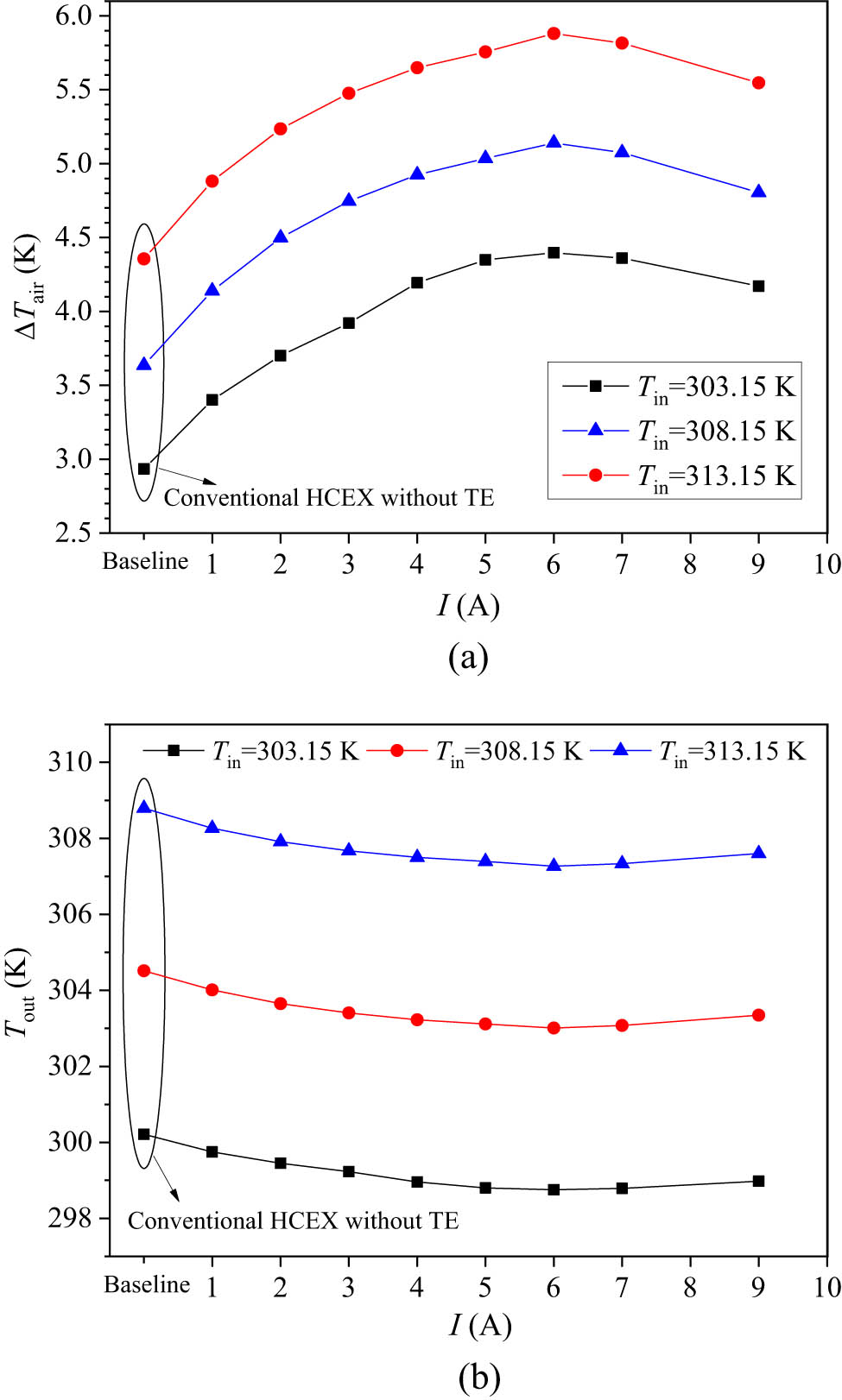
Temperature drop and outlet temperature of the TE-integrated HCEX under various input currents when the inlet air temperature is 303.15, 308.15, and 313.15 K and inlet air velocity is 20 m s−1. (a) Temperature drop of air. (b) Outlet temperature of air.
According to Figures 12 and 13, as the inlet temperature of air increases, the longitudinal temperature difference between the hot air and the cold wall of the helically coiled tubes gets larger. The total cooling rate of the conventional HCEX and TE-integrated HCEX increases accordingly. Thus, the cooling rate Q c,total of the conventional HCEX can provide 2889.46–4288.01 W cooling capacity as the inlet temperature of air varies from 303.15 to 313.15 K at constant inlet air velocity of 20 m s−1 and water cooling capability. This is beneficial for the enlargement of the temperature gradient between the hot air and the cold wall of the helically coiled tube under specific heat transfer coefficient and heat exchange area, resulting in an average increase of 17% when inlet air temperature rises. When the TE module is integrated, the total cooling rate increases under certain inlet air temperature. The additional cold source contributed by TE module, Q c,TE, has a slightly increasing variation of average 6% with the increase in the inlet air temperature, which is mainly accounted by the enlarged Peltier heat. The maximum Q c,TE at optimal input current is 2155.17–2350.56 W and the maximum total cooling rate Q c,total is 4328.37–5788.95 W when the inlet air temperature is 303.15–313.15 K. Compared to the conventional HCEX, the maximum enhancement degree for the TE-integrated HCEX is 49.8, 41.4, and 35.0%, respectively.

Temperature contours of air fluid in the TE-integrated HCEX with FR 100% at input current of 6 A when the inlet air temperature is 303.15 K and 313.15 K, and inlet air velocity is 20 m s−1. (a) Temperature contour of air fluid at cross sections of Y = 0, ±0.16, ±0.36 m and X = 0 m in the TE-integrated HCEX with FR of 100% at 303.15 K. (b) Temperature contour of air fluid at cross sections of Y = 0, ±0.16, ±0.36 m and X = 0 m in the TE-integrated HCEX with FR of 100% at 313.15 K.

Cooling rate of the TE-integrated HCEX under various input currents when inlet air temperature varies from 303.15 to 313.15 K and inlet air velocity is 20 m s−1.
Under the constant air inlet velocity of 20 m s−1, the coefficient of performance, COPTE, monotonically decreases with the increase in input current and there is a slight difference under different air inlet temperatures within input currents of 3 A, as shown in Figure 14. For conventional HCEX, the cooling effectiveness is 16.24%, which is not affected by the inlet air temperature. Comparatively, the cooling effectiveness has a more obvious difference for the TE-integrated HCEX when the inlet air temperature changes. Lower inlet air temperature corresponds to a higher cooling effectiveness of the heat exchanger. The cooling effectiveness is 24.35, 22.76, and 21.73% when inlet air temperature is 303.15, 308.15, and 313.15 K. Thus, the integration of TE module to the conventional heat exchanger can tackle the problem of enhancement of underground coal mine air cooling performance without the requirement for significant extra space, especially at lower air inlet temperature.

Coefficient of performance for the TE modules and cooling effectiveness of the TE-integrated HCEX under various input currents, when inlet air temperature varies from 303.15 to 313.15 K and inlet air velocity is 20 m s−1.
3.4 Effect of air inlet velocity on air cooling capacity for TE-integrated HCEX
This section investigates the effect of inlet air velocity on air cooling performance for the TE-integrated HCEX under the condition of 100% TE FR. The inlet velocity of air varies from 10 to 25 m s−1 for the following numerical simulations. The inlet air temperature is kept constant at 308.15 K and the cold side convective heat transfer coefficient is 1,600 W m−2 K with average cold-water temperature of 283.15 K. According to Figure 15, for the TE-integrated HCEX, the temperature drop of the air fluid decreases with the increase in air inlet velocity, while the outlet air temperature increases when the inlet velocity increases. The optimal input current to achieve cooler air at various inlet velocities is around 6–7 A for the studied cases. When the inlet air velocity gets increased from 10 to 25 m s−1, for TE-integrated HCEX, the lowest air outlet temperatures are 301.91–303.38 K, corresponding to the maximum temperature drops of 6.24–4.77 K under optimal input current. The reason can be explained as follows: the total amount of heat exchange rate is contributed by the cold side Peltier heat from the TE module as well as the convective heat removal by the cold helically coiled tubes. When the velocity increases, the flow rate of air is significantly increased, and the temperature difference between cold walls and the air flow is decreased in the TE-integrated HCEX. Meanwhile, the shell side heat transfer coefficient is proportional to the inlet velocity of air, which means that the increase in the velocity will improve the heat transfer efficiency and the total cooling rate is increased. The combined effect of the decreased temperature difference and increased heat transfer rate ultimately reflected in an increase in the outlet temperature when the inlet velocity of air increases from 10 to 25 m s−1, with constant temperature of inlet air and constant water-cooling coefficient.

Temperature drop and outlet temperature of air in the TE-integrated HCEX under various input currents when the inlet air velocity is 10–25 m s−1 and inlet air temperature is 308.15 K. (a) Temperature drop of air. (b) Outlet temperature of air.
Figure 16 shows the total cooling rate of the conventional HCEX and TE-integrated HCEX. It can be found that the total cooling rate Q c,total of the conventional HCEX can provide 2118.29–4241.28 W cooling capacity as the inlet velocity of air varies from 10 to 25 m s−1 at constant inlet air temperature of 308.15 K and constant water cooling condition. For the TE-integrated HCEX, the total cooling rate Q c,total and the additional cold source contributed by TE module, Q c,TE, increases with increase in the inlet air velocity. When the inlet air velocity increases with the step of 5 m s−1 from 10 to 15 m s−1, the total cooling rate Q c,total increase by 34.3% and the cooling rate by TE module Q c,TE can increase by 27.2%. When the inlet velocity increase by 5 m s−1 from 15 to 20 m s−1, the total cooling rate Q c,total increase by 22.8% and the cooling rate by TE module Q c,TE can increase by 17.2%. When the inlet velocity increase by 5 m s−1 from 20 to 25 m s−1, the total cooling rate Q c,total increase by 17.5% and the cooling rate by TE module Q c,TE can increase by 13.6%. It means that the increase in air velocity provides more air flow rate. The faster flow velocity is beneficial for higher heat transfer rate between the cold medium and the air flow. The additional cold source contributed by TE module, Q c,TE accounted by the Peltier heat also increases because of the decreased thermal resistance at the shell side of the HCEX when the air velocity is increased. When the inlet air velocity ranges between 10 and 25 m s−1 and air inlet temperature is kept at 308.15 K, the maximum Q c,TE at optimal input current is 1473.81–2549.55 W and the maximum total cooling rate Q c,total is 3069.21 to 5873.52 W compared to the conventional HCEX, the maximum enhancement degree for the TE-integrated HCEX is 44.9, 42.2, 39.6, and 38.6% at inlet air velocity of 10, 15, 20, and 25 m s−1, respectively.

Cooling rate of the TE-integrated HCEX under various input currents when inlet air velocity varies from 10 to 25 m s−1, and inlet air temperature is 308.15 K.
Figure 17 shows coefficient of performance for the TE modules and cooling effectiveness of the TE-integrated HCEX under various input currents. Under the working condition that inlet air velocity varies from 10 to 25 m s−1 with constant inlet air temperature of 308.15 K, it can be found that the coefficient of performance, COPTE, also monotonically decreases with the increase in input current. The difference under different air inlet velocities is obvious and the larger air velocity corresponds to larger coefficient of performance, COPTE of the TE modules. This is because the input power for different inlet velocity condition does not change obviously and the pumping penalty of the water-cooling channel at the cold side of the TE module is kept constant, the cooling power contributed by the TE module Q c,TE increases by 27.2–17.6% when the inlet velocity increases from 10 to 25 m s−1. Thus, the COPTE of the TE modules increases under higher inlet velocity.

Coefficient of performance for the TE modules and cooling effectiveness of the TE-integrated HCEX under various input currents, when inlet air velocity varies from 10 to 25 m s−1, and inlet air temperature is 308.15 K.
However, the cooling effect decreases with the increase in the inlet air velocity because the air temperature drop at the inlet and outlet decreases as analyzed above. For conventional HCEX, the cooling effectiveness is 18.31–15.74% when the inlet velocity increases from 10 to 25 m s−1. Comparatively, the cooling effectiveness for the TE-integrated HCEX at lower inlet air velocity also results in a higher cooling effectiveness of the heat exchanger. The maximum cooling effectiveness is 26.49, 24.19, 22.76, and 21.73% when the inlet air velocity is 10, 15, 20, and 25 m s−1. The reason can be explained by the temperature distribution phenomenon analyzed above. That is, the reduction in heat transfer resistance under higher inlet velocity is beneficial for the increase in the total cooling rate, whereas the temperature difference of such air-cooling device is reduced simultaneously. The combined effect of the decreased temperature difference and increased heat transfer rate ultimately reflected in an increase in the outlet temperature and thus, the temperature of the air-cooling device drops when the inlet temperature of air is constant. Thus, the cooling effectiveness decreases slightly with the increase in the inlet air velocity.
4 Conclusion
Developing advanced underground mine air cooler to adjust the temperature of the underground mine environment is of significance for ensuring high-efficient, thermal-comfort and safe mining activities. The mine space is limited and hence, the air cooler compactness and efficiency needs to be further improved. This work proposes a TE-integrated HCEX to improve the cooling performance based on conventional HCEX for underground mine coolers. Multiphysics numerical model for the fluid-thermal-electric performance simulation is established under typical underground coal mine air temperature conditions near the working face. The main findings are as follows:
The results show that the TE-integrated HCEX is able to well improve the cooling capacity without introducing obvious space requirements. The average temperature on the cold surface of the TE module contacting with the external shell wall is around 230 K at optimal input current, which is much below the cold water of 283.15 K. Thus, the TE module can effectively serve as an additional cold source apart from the cold helically coiled tube. The cooler air at the outlet and larger air temperature drop can be achieved when the TE module is utilized.
The increase in the FR of TE from 50 to 100% would continuously benefit for larger cooling capacity. Under constant air inlet temperature of 308.15 K and inlet velocity of 20 m s−1, the largest inlet and outlet air temperature difference changes from 4.21 to 5.14 K at the optimal input current of 6 A when TE FR is between 50 and 100%, indicating an enhancement of the cooling capacity by around 16–41%. When the TE FR is 100%, the cooling capacity gets most enhanced, and the TE cooling rate Q c,TE is 1047.61–2252.78 W and the total cooling rate Q c,total varies from 4074.37 to 5060.58 W. The maximum total cooling rate Q c,total of 5060.58 W at the optimal input current of 6 A gives the largest enhancement degree of 41.4%.
The effect of air inlet temperature and inlet velocity on the cooling performance is investigated with the best design of the TE-integrated HCEX with FR of 100%. Under constant inlet velocity, as the inlet temperature of air increases from 303.15 to 313.15 K, the temperature difference between the hot air and the cold walls gets larger, the cooling rate increases and cooling effectiveness decreases. The COPTE does not change much. As the inlet velocity of air increases from 10 to 25 m s−1 under constant inlet temperature, the temperature difference between the hot air and the cold walls gets decreased, the cooling rate, the COPTE increases and cooling effectiveness decreased. Within the range of the air inlet conditions in this work, the maximum enhancement degree of the total cooling rate Q c,total for the TE-integrated one is 49.8%∼35.0%. The maximum cooling effectiveness at optimal working current of 6 A is 21.73–26.49% for the TE-integrated HCEX, which is higher than the effectiveness of the conventional HCEX of 15.74–18.24%.
In summary, the feasibility of the TE-integrated HCEX is proven to be effective in the enhancement of underground coal mine air cooling performance without requirement for significant extra space. The experimental validation under real mine conditions would be our prompt next step of work to confirm the practical applicability of the newly proposed air-cooling device in the field of high temperature heat hazard control for the coal mining industry. The impact of varying the geometrical parameter design of the heat exchanger, as well as various working and operational conditions such as dust and humidity encountered in real coal mines on the system cooling performance, and the multi-parameter optimization considering the coupling influence of design and operational parameters for the TE-integrated HCEX would be explored through further studies.
-
Funding information: This work is supported by the National Natural Science Foundation of China (52004210), Shaanxi Postdoctoral Foundation (2023BSHYDZZ155) and Natural Science Basic Research Plan of Shaanxi Province (2024JC-YBQN-0422).
-
Author contributions: Xing Lu: writing – original draft, methodology, conceptualization, and project administration; Renkun Dai: investigation, validation, and formal analysis; Jun Deng: supervision, resources, writing – review and editing; Ting Ma: methodology, supervision, and writing – review and editing. All authors have accepted responsibility for the entire content of this manuscript and approved its submission.
-
Conflict of interest: The authors state no conflict of interest.
-
Data availability statement: All data generated or analyzed during this study are included in this published article.
References
[1] IEA. Coal mid-year update - July 2024. Paris: IEA; 2024. https://www.iea.org/reports/coal-mid-year-update-july-2024. Licence: CC BY 4.0.Search in Google Scholar
[2] Zhang HJ, Ding GZ, Li Z, Huang JC. A simple design method of mine spiral coil air cooler. Low Temp Spec Gases. 2019;37:11–5. 10.3969/j.issn.1007-7804.2019.05.003 (in Chinese).Search in Google Scholar
[3] Xu Y, Li ZJ, Chen Y, Jia MT, Zhang MS, Li RR. Synergetic mining of geothermal energy in deep mines: An innovative method for heat hazard control. Appl Therm Eng. 2022;210:118398. 10.1016/j.applthermaleng.2022.118398.Search in Google Scholar
[4] Millar DK, Trapani K, Romero A. Deep mine cooling, a case for Northern Ontario: Part I. Int J Min Sci Technol. 2016;26(4):721–7. 10.1016/j.ijmst.2016.05.026.Search in Google Scholar
[5] van Staden HJ, van Rensburg JF, Groenewald HJ. Optimal use of mobile cooling units in a deep-level gold mine. Int J Min Sci Technol. 2020;30(4):547–53. 10.1016/j.ijmst.2020.03.004.Search in Google Scholar
[6] Guo PY, He MC, Zheng LG, Zhang N. A geothermal recycling system for cooling and heating in deep mines. Appl Therm Eng. 2017;116:833–9. 10.1016/j.applthermaleng.2017.01.116.Search in Google Scholar
[7] Lu X, Tong XL, Deng J, Xiao Y, Du XP. Numerical investigation on thermal-hydraulic performance of helical-coiled tube air cooler used for underground mine. Comput Chem Eng. 2022;166:107966. 10.1016/j.compchemeng.2022.107966.Search in Google Scholar
[8] Szlązak N, Obracaj D, Swolkień J. An evaluation of the functioning of cooling systems in the Polish coal mine industry. Energies. 2018;11(9):2267. 10.3390/en11092267.Search in Google Scholar
[9] Gholizadeh A, Pourfallah M, Gholinia M, Armin M, Languri E. The role of nanofluids and fins in a heat exchanger on waste energy recovery from a diesel engine: An experimental and numerical study. Energy Rep. 2022;8:13353–68. 10.1016/j.egyr.2022.10.009.Search in Google Scholar
[10] Ghadikolaei SS, Siahchehrehghadikolaei S, Gholinia M, Rahimi M. A CFD modeling of heat transfer between CGNPs/H2O eco-friendly nanofluid and the novel nature-based designs heat sink: Hybrid passive techniques for CPU cooling. Therm Sci Eng Prog. 2023;37:101604. 10.1016/j.tsep.2022.101604.Search in Google Scholar
[11] Song H, Cao CJ, Chen HW, Liu N. Design of mine spiral plate heat exchanger. Coal Mine Mach. 2015;36(5):37–9. 10.13436/j.mkjx.201505016 (in Chinese).Search in Google Scholar
[12] Wang YJ, Wang YJ, Sun L, Yang JH, Zhong H. An investigation on shell-side thermal–hydraulic performance of helically coiled tube heat exchanger for deep underground space. Appl Therm Eng. 2024;248(Part A):123157. 10.1016/j.applthermaleng.2024.123157.Search in Google Scholar
[13] Bell LE. Cooling, heating, generating power, and recovering waste heat with thermoelectric systems. Science. 2008;321(5895):1457–61. 10.1126/science.1158899.Search in Google Scholar PubMed
[14] Huang LYJ, Zheng YH, Xing LY, Hou BZ. Recent progress of thermoelectric applications for cooling/heating, power generation, heat flux sensor and potential prospect of their integrated applications. Therm Sci Eng Prog. 2023;45:102064. 10.1016/j.tsep.2023.102064.Search in Google Scholar
[15] Sheikholeslami M, Khalili Z, Scardi P, Ataollahi N. Concentrated solar photovoltaic cell equipped with thermoelectric layer in presence of nanofluid flow within porous heat sink: Impact of dust accumulation. Sustain Cities Soc. 2023;98:104866. 10.1016/j.scs.2023.104866.Search in Google Scholar
[16] Sheikholeslami M, Khalili Z. Investigation of solar photovoltaic cell utilizing hybrid nanofluid confined jet and helical fins for improving electrical efficiency in existence of thermoelectric module. Appl Therm Eng. 2023;234:121329. 10.1016/j.applthermaleng.2023.121329.Search in Google Scholar
[17] Sheikholeslami M, Khalili Z, Momayez L. Efficiency improvement of ternary nanofluid within a solar photovoltaic unit combined with thermoelectric considering environmental analysis. Environ Technol Innov. 2023;32:103315. 10.1016/j.eti.2023.103315.Search in Google Scholar
[18] Cai Y, Wang L, Wang WW, Liu D, Zhao FY. Solar energy harvesting potential of a photovoltaic-thermoelectric cooling and power generation system: Bidirectional modeling and performance optimization. J Clean Prod. 2020;254:120150. 10.1016/j.jclepro.2020.120150.Search in Google Scholar
[19] Qin Y, Zhang HC, Zhang XF. Integrating high-temperature proton exchange membrane fuel cell with duplex thermoelectric cooler for electricity and cooling cogeneration. Int J Hydrogen Energy. 2022;47(91):38703–20. 10.1016/j.ijhydene.2022.09.041.Search in Google Scholar
[20] Gong TR, Li LH, Shi ML, Kang LF, Gao L, Li JT. Performance assessment and optimization of a thin-film thermoelectric cooler for on-chip transient thermal management. Appl Therm Eng. 2023;224:120079. 10.1016/j.applthermaleng.2023.120079.Search in Google Scholar
[21] Singh VK, Sisodia SS, Patel A, Shah T, Das P, Patel RN, et al. Thermoelectric cooler (TEC) based thermal control system for space applications: Numerical study. Appl Therm Eng. 2023;224:120101. 10.1016/j.applthermaleng.2023.120101.Search in Google Scholar
[22] Luo D, Yan YY, Chen WH, Yang XL, Chen H, Cao BY, et al. A comprehensive hybrid transient CFD-thermal resistance model for automobile thermoelectric generators. Int J Heat Mass Transf. 2023;211:124203. 10.1016/j.ijheatmasstransfer.2023.124203.Search in Google Scholar
[23] Attar A, Lee H. Designing and testing the optimum design of automotive air-to-air thermoelectric air conditioner (TEAC) system. Energy Convers Manage. 2016;112:328–36. 10.1016/j.enconman.2016.01.029.Search in Google Scholar
[24] Kim DH, Seo S, Kim S, Shin S, Son K, Jeon SJ, et al. Design and performance analyses of thermoelectric coolers and power generators for automobiles. Sustain Energy Technol Assess. 2022;51:101955. 10.1016/j.seta.2022.101955.Search in Google Scholar
[25] Saini A, Watzman SJ, Bahk JH. Cost-performance trade-off in thermoelectric air conditioning system with graded and constant material properties. Energ Build. 2021;240(8):110931. 10.1016/j.enbuild.2021.110931.Search in Google Scholar
[26] Cai Y, Wang L, Ding WT, Liu D, Zhao FY. Thermal performance of an active thermoelectric ventilation system applied for built space cooling: Network model and finite time thermodynamic optimization. Energy. 2019;170:915–30. 10.1016/j.energy.2018.12.186.Search in Google Scholar
[27] Su XS, Zhang L, Liu ZB, Luo YQ, Chen DP, Li WJ. Performance evaluation of a novel building envelope integrated with thermoelectric cooler and radiative sky cooler. Renew Energy. 2021;171:1061–78. 10.1016/j.renene.2021.02.164.Search in Google Scholar
[28] Zhao DL, Lu X, Fan TZ, Wu YS, Lou L, Wang QW, et al. Personal thermal management using portable thermoelectrics for potential building energy saving. Appl Energy. 2018;218:282–91. 10.1016/j.apenergy.2018.02.158.Search in Google Scholar
[29] Xu Y, Li ZJ, Wang JJ, Zhang MS, Jia MT, Wang QL. Man-portable cooling garment with cold liquid circulation based on thermoelectric refrigeration. Appl Therm Eng. 2022;200:117730. 10.1016/j.applthermaleng.2021.117730.Search in Google Scholar
[30] Meng JH, Wu HC, Gao DY, Kai Z, Lu G, Yan WM. A novel super-cooling enhancement method for a two-stage thermoelectric cooler using integrated triangular-square current pulses. Energy. 2021;217:119360. 10.1016/j.energy.2020.119360.Search in Google Scholar
[31] Zhao DL, Tan G. A review of thermoelectric cooling: Materials, modeling and applications. Appl Therm Eng. 2014;66(1–2):15–24. 10.1016/j.applthermaleng.2014.01.074.Search in Google Scholar
[32] Chen M, Snyder GJ. Analytical and numerical parameter extraction for compact modeling of thermoelectric coolers. Int J Heat Mass Transf. 2013;60:689–99. 10.1016/j.ijheatmasstransfer.2013.01.020.Search in Google Scholar
[33] Ma T, Lu X, Pandit J, Ekkad SV, Huxtable ST, Deshpande S, et al. Numerical study on thermoelectric-hydraulic performance of a thermoelectric power generator with a plate-fin heat exchanger with longitudinal vortex generators. Appl Energy. 2017;185(Part 2):1343–54. 10.1016/j.apenergy.2016.01.078.Search in Google Scholar
[34] ANSYS, Inc. ANSYS fluent theory guide. Canonsburg, PA: ANSYS Inc; 2012.Search in Google Scholar
[35] Lu X, Du XP, Zeng M, Zhang S, Wang QW. Shell-side thermal-hydraulic performances of multilayer spiral-wound heat exchangers under different wall thermal boundary conditions. Appl Therm Eng. 2014;70(2):1216–27. 10.1016/j.applthermaleng.2014.02.053.Search in Google Scholar
[36] Zhou CH, Zarrella A, Yao Y, Ni L. Analysis of the effect of icing on the thermal behavior of helical coil heat exchangers in surface water heat pump application. Int J Heat Mass Transf. 2022;183(Part A):122074. 10.1016/j.ijheatmasstransfer.2021.122074.Search in Google Scholar
[37] Yamashita O. Effect of linear and non-linear components in the temperature dependences of thermoelectric properties on the cooling performance. Appl Energy. 2009;86:1746–56. 10.1016/j.apenergy.2008.12.006.Search in Google Scholar
[38] Jang JY, Tsai YC. Optimization of thermoelectric generator module spacing and spreader thickness used in a waste heat recovery system. Appl Therm Eng. 2013;51(1–2):677–89. 10.1016/j.applthermaleng.2012.10.024.Search in Google Scholar
[39] Wang KP, Li QM, Wang J, Yang SB. Thermodynamic characteristics of deep space: hot hazard control case study in 1010-m-deep mine. Case Stud Therm Eng. 2021;28:101656. 10.1016/j.csite.2021.101656.Search in Google Scholar
[40] Wang JH, Wan ZJ, Zhang HW, Wang JC, Wang Y, Zhang Y, et al. Effects of thermal water upwelling on microclimate change in the high geo-temperature roadway. Shock Vib. 2021;1:6639413. 10.1155/2021/6639413.Search in Google Scholar
[41] Li ZJ, Xu Y, Jia MT, Liu HS, Pan W, Deng YF. Numerical simulation on heat hazard control by collaborative geothermal exploitation in deep mine. J Cent South Univ (Sci Technol). 2021;52(3):671–80. 10.11817/j.issn.1672-7207.2021.03.002 (in Chinese).Search in Google Scholar
[42] Tao W. Heat transfer. 5th edn. Beijing: Higher Education Press; 2019.Search in Google Scholar
[43] Chen M, Rosendahl LA, Condra T. A three-dimensional numerical model of thermoelectric generators in fluid power systems. Int J Heat Mass Transf. 2011;54(1–3):345–55. 10.1016/j.ijheatmasstransfer.2010.08.024.Search in Google Scholar
[44] Jaegle M. Multiphysics simulation of thermoelectric systems - modeling of Peltier cooling and thermoelectric generation. Proceedings of the COMSOL Conference. Hannover; 2008.Search in Google Scholar
[45] Xin S, Gao HZ, Wang LT, Wang WG. Cooling technology of water storage at low temperature in Gob area. Saf Coal Mines. 2016;47(8):82–5. 10.13347/j.cnki.mkaq.2016.08.023 (in Chinese).Search in Google Scholar
© 2025 the author(s), published by De Gruyter
This work is licensed under the Creative Commons Attribution 4.0 International License.
Articles in the same Issue
- Research Articles
- Single-step fabrication of Ag2S/poly-2-mercaptoaniline nanoribbon photocathodes for green hydrogen generation from artificial and natural red-sea water
- Abundant new interaction solutions and nonlinear dynamics for the (3+1)-dimensional Hirota–Satsuma–Ito-like equation
- A novel gold and SiO2 material based planar 5-element high HPBW end-fire antenna array for 300 GHz applications
- Explicit exact solutions and bifurcation analysis for the mZK equation with truncated M-fractional derivatives utilizing two reliable methods
- Optical and laser damage resistance: Role of periodic cylindrical surfaces
- Numerical study of flow and heat transfer in the air-side metal foam partially filled channels of panel-type radiator under forced convection
- Water-based hybrid nanofluid flow containing CNT nanoparticles over an extending surface with velocity slips, thermal convective, and zero-mass flux conditions
- Dynamical wave structures for some diffusion--reaction equations with quadratic and quartic nonlinearities
- Solving an isotropic grey matter tumour model via a heat transfer equation
- Study on the penetration protection of a fiber-reinforced composite structure with CNTs/GFP clip STF/3DKevlar
- Influence of Hall current and acoustic pressure on nanostructured DPL thermoelastic plates under ramp heating in a double-temperature model
- Applications of the Belousov–Zhabotinsky reaction–diffusion system: Analytical and numerical approaches
- AC electroosmotic flow of Maxwell fluid in a pH-regulated parallel-plate silica nanochannel
- Interpreting optical effects with relativistic transformations adopting one-way synchronization to conserve simultaneity and space–time continuity
- Modeling and analysis of quantum communication channel in airborne platforms with boundary layer effects
- Theoretical and numerical investigation of a memristor system with a piecewise memductance under fractal–fractional derivatives
- Tuning the structure and electro-optical properties of α-Cr2O3 films by heat treatment/La doping for optoelectronic applications
- High-speed multi-spectral explosion temperature measurement using golden-section accelerated Pearson correlation algorithm
- Dynamic behavior and modulation instability of the generalized coupled fractional nonlinear Helmholtz equation with cubic–quintic term
- Study on the duration of laser-induced air plasma flash near thin film surface
- Exploring the dynamics of fractional-order nonlinear dispersive wave system through homotopy technique
- The mechanism of carbon monoxide fluorescence inside a femtosecond laser-induced plasma
- Numerical solution of a nonconstant coefficient advection diffusion equation in an irregular domain and analyses of numerical dispersion and dissipation
- Numerical examination of the chemically reactive MHD flow of hybrid nanofluids over a two-dimensional stretching surface with the Cattaneo–Christov model and slip conditions
- Impacts of sinusoidal heat flux and embraced heated rectangular cavity on natural convection within a square enclosure partially filled with porous medium and Casson-hybrid nanofluid
- Stability analysis of unsteady ternary nanofluid flow past a stretching/shrinking wedge
- Solitonic wave solutions of a Hamiltonian nonlinear atom chain model through the Hirota bilinear transformation method
- Bilinear form and soltion solutions for (3+1)-dimensional negative-order KdV-CBS equation
- Solitary chirp pulses and soliton control for variable coefficients cubic–quintic nonlinear Schrödinger equation in nonuniform management system
- Influence of decaying heat source and temperature-dependent thermal conductivity on photo-hydro-elasto semiconductor media
- Dissipative disorder optimization in the radiative thin film flow of partially ionized non-Newtonian hybrid nanofluid with second-order slip condition
- Bifurcation, chaotic behavior, and traveling wave solutions for the fractional (4+1)-dimensional Davey–Stewartson–Kadomtsev–Petviashvili model
- New investigation on soliton solutions of two nonlinear PDEs in mathematical physics with a dynamical property: Bifurcation analysis
- Mathematical analysis of nanoparticle type and volume fraction on heat transfer efficiency of nanofluids
- Creation of single-wing Lorenz-like attractors via a ten-ninths-degree term
- Optical soliton solutions, bifurcation analysis, chaotic behaviors of nonlinear Schrödinger equation and modulation instability in optical fiber
- Chaotic dynamics and some solutions for the (n + 1)-dimensional modified Zakharov–Kuznetsov equation in plasma physics
- Fractal formation and chaotic soliton phenomena in nonlinear conformable Heisenberg ferromagnetic spin chain equation
- Single-step fabrication of Mn(iv) oxide-Mn(ii) sulfide/poly-2-mercaptoaniline porous network nanocomposite for pseudo-supercapacitors and charge storage
- Novel constructed dynamical analytical solutions and conserved quantities of the new (2+1)-dimensional KdV model describing acoustic wave propagation
- Tavis–Cummings model in the presence of a deformed field and time-dependent coupling
- Spinning dynamics of stress-dependent viscosity of generalized Cross-nonlinear materials affected by gravitationally swirling disk
- Design and prediction of high optical density photovoltaic polymers using machine learning-DFT studies
- Robust control and preservation of quantum steering, nonlocality, and coherence in open atomic systems
- Coating thickness and process efficiency of reverse roll coating using a magnetized hybrid nanomaterial flow
- Dynamic analysis, circuit realization, and its synchronization of a new chaotic hyperjerk system
- Decoherence of steerability and coherence dynamics induced by nonlinear qubit–cavity interactions
- Finite element analysis of turbulent thermal enhancement in grooved channels with flat- and plus-shaped fins
- Modulational instability and associated ion-acoustic modulated envelope solitons in a quantum plasma having ion beams
- Statistical inference of constant-stress partially accelerated life tests under type II generalized hybrid censored data from Burr III distribution
- On solutions of the Dirac equation for 1D hydrogenic atoms or ions
- Entropy optimization for chemically reactive magnetized unsteady thin film hybrid nanofluid flow on inclined surface subject to nonlinear mixed convection and variable temperature
- Stability analysis, circuit simulation, and color image encryption of a novel four-dimensional hyperchaotic model with hidden and self-excited attractors
- A high-accuracy exponential time integration scheme for the Darcy–Forchheimer Williamson fluid flow with temperature-dependent conductivity
- Novel analysis of fractional regularized long-wave equation in plasma dynamics
- Development of a photoelectrode based on a bismuth(iii) oxyiodide/intercalated iodide-poly(1H-pyrrole) rough spherical nanocomposite for green hydrogen generation
- Investigation of solar radiation effects on the energy performance of the (Al2O3–CuO–Cu)/H2O ternary nanofluidic system through a convectively heated cylinder
- Quantum resources for a system of two atoms interacting with a deformed field in the presence of intensity-dependent coupling
- Studying bifurcations and chaotic dynamics in the generalized hyperelastic-rod wave equation through Hamiltonian mechanics
- A new numerical technique for the solution of time-fractional nonlinear Klein–Gordon equation involving Atangana–Baleanu derivative using cubic B-spline functions
- Interaction solutions of high-order breathers and lumps for a (3+1)-dimensional conformable fractional potential-YTSF-like model
- Hydraulic fracturing radioactive source tracing technology based on hydraulic fracturing tracing mechanics model
- Numerical solution and stability analysis of non-Newtonian hybrid nanofluid flow subject to exponential heat source/sink over a Riga sheet
- Numerical investigation of mixed convection and viscous dissipation in couple stress nanofluid flow: A merged Adomian decomposition method and Mohand transform
- Effectual quintic B-spline functions for solving the time fractional coupled Boussinesq–Burgers equation arising in shallow water waves
- Analysis of MHD hybrid nanofluid flow over cone and wedge with exponential and thermal heat source and activation energy
- Solitons and travelling waves structure for M-fractional Kairat-II equation using three explicit methods
- Impact of nanoparticle shapes on the heat transfer properties of Cu and CuO nanofluids flowing over a stretching surface with slip effects: A computational study
- Computational simulation of heat transfer and nanofluid flow for two-sided lid-driven square cavity under the influence of magnetic field
- Irreversibility analysis of a bioconvective two-phase nanofluid in a Maxwell (non-Newtonian) flow induced by a rotating disk with thermal radiation
- Hydrodynamic and sensitivity analysis of a polymeric calendering process for non-Newtonian fluids with temperature-dependent viscosity
- Exploring the peakon solitons molecules and solitary wave structure to the nonlinear damped Kortewege–de Vries equation through efficient technique
- Modeling and heat transfer analysis of magnetized hybrid micropolar blood-based nanofluid flow in Darcy–Forchheimer porous stenosis narrow arteries
- Activation energy and cross-diffusion effects on 3D rotating nanofluid flow in a Darcy–Forchheimer porous medium with radiation and convective heating
- Insights into chemical reactions occurring in generalized nanomaterials due to spinning surface with melting constraints
- Influence of a magnetic field on double-porosity photo-thermoelastic materials under Lord–Shulman theory
- Soliton-like solutions for a nonlinear doubly dispersive equation in an elastic Murnaghan's rod via Hirota's bilinear method
- Analytical and numerical investigation of exact wave patterns and chaotic dynamics in the extended improved Boussinesq equation
- Nonclassical correlation dynamics of Heisenberg XYZ states with (x, y)-spin--orbit interaction, x-magnetic field, and intrinsic decoherence effects
- Exact traveling wave and soliton solutions for chemotaxis model and (3+1)-dimensional Boiti–Leon–Manna–Pempinelli equation
- Unveiling the transformative role of samarium in ZnO: Exploring structural and optical modifications for advanced functional applications
- On the derivation of solitary wave solutions for the time-fractional Rosenau equation through two analytical techniques
- Analyzing the role of length and radius of MWCNTs in a nanofluid flow influenced by variable thermal conductivity and viscosity considering Marangoni convection
- Advanced mathematical analysis of heat and mass transfer in oscillatory micropolar bio-nanofluid flows via peristaltic waves and electroosmotic effects
- Exact bound state solutions of the radial Schrödinger equation for the Coulomb potential by conformable Nikiforov–Uvarov approach
- Some anisotropic and perfect fluid plane symmetric solutions of Einstein's field equations using killing symmetries
- Nonlinear dynamics of the dissipative ion-acoustic solitary waves in anisotropic rotating magnetoplasmas
- Curves in multiplicative equiaffine plane
- Exact solution of the three-dimensional (3D) Z2 lattice gauge theory
- Propagation properties of Airyprime pulses in relaxing nonlinear media
- Symbolic computation: Analytical solutions and dynamics of a shallow water wave equation in coastal engineering
- Wave propagation in nonlocal piezo-photo-hygrothermoelastic semiconductors subjected to heat and moisture flux
- Comparative reaction dynamics in rotating nanofluid systems: Quartic and cubic kinetics under MHD influence
- Laplace transform technique and probabilistic analysis-based hypothesis testing in medical and engineering applications
- Physical properties of ternary chloro-perovskites KTCl3 (T = Ge, Al) for optoelectronic applications
- Gravitational length stretching: Curvature-induced modulation of quantum probability densities
- The search for the cosmological cold dark matter axion – A new refined narrow mass window and detection scheme
- A comparative study of quantum resources in bipartite Lipkin–Meshkov–Glick model under DM interaction and Zeeman splitting
- PbO-doped K2O–BaO–Al2O3–B2O3–TeO2-glasses: Mechanical and shielding efficacy
- Nanospherical arsenic(iii) oxoiodide/iodide-intercalated poly(N-methylpyrrole) composite synthesis for broad-spectrum optical detection
- Sine power Burr X distribution with estimation and applications in physics and other fields
- Numerical modeling of enhanced reactive oxygen plasma in pulsed laser deposition of metal oxide thin films
- Dynamical analyses and dispersive soliton solutions to the nonlinear fractional model in stratified fluids
- Computation of exact analytical soliton solutions and their dynamics in advanced optical system
- An innovative approximation concerning the diffusion and electrical conductivity tensor at critical altitudes within the F-region of ionospheric plasma at low latitudes
- An analytical investigation to the (3+1)-dimensional Yu–Toda–Sassa–Fukuyama equation with dynamical analysis: Bifurcation
- Swirling-annular-flow-induced instability of a micro shell considering Knudsen number and viscosity effects
- Numerical analysis of non-similar convection flows of a two-phase nanofluid past a semi-infinite vertical plate with thermal radiation
- MgO NPs reinforced PCL/PVC nanocomposite films with enhanced UV shielding and thermal stability for packaging applications
- Optimal conditions for indoor air purification using non-thermal Corona discharge electrostatic precipitator
- Investigation of thermal conductivity and Raman spectra for HfAlB, TaAlB, and WAlB based on first-principles calculations
- Tunable double plasmon-induced transparency based on monolayer patterned graphene metamaterial
- DSC: depth data quality optimization framework for RGBD camouflaged object detection
- A new family of Poisson-exponential distributions with applications to cancer data and glass fiber reliability
- Numerical investigation of couple stress under slip conditions via modified Adomian decomposition method
- Monitoring plateau lake area changes in Yunnan province, southwestern China using medium-resolution remote sensing imagery: applicability of water indices and environmental dependencies
- Heterodyne interferometric fiber-optic gyroscope
- Exact solutions of Einstein’s field equations via homothetic symmetries of non-static plane symmetric spacetime
- A widespread study of discrete entropic model and its distribution along with fluctuations of energy
- Empirical model integration for accurate charge carrier mobility simulation in silicon MOSFETs
- The influence of scattering correction effect based on optical path distribution on CO2 retrieval
- Anisotropic dissociation and spectral response of 1-Bromo-4-chlorobenzene under static directional electric fields
- Role of tungsten oxide (WO3) on thermal and optical properties of smart polymer composites
- Analysis of iterative deblurring: no explicit noise
- 10.1515/phys-2025-0251
- Review Article
- Examination of the gamma radiation shielding properties of different clay and sand materials in the Adrar region
- Erratum
- Erratum to “On Soliton structures in optical fiber communications with Kundu–Mukherjee–Naskar model (Open Physics 2021;19:679–682)”
- Special Issue on Fundamental Physics from Atoms to Cosmos - Part II
- Possible explanation for the neutron lifetime puzzle
- Special Issue on Nanomaterial utilization and structural optimization - Part III
- Numerical investigation on fluid-thermal-electric performance of a thermoelectric-integrated helically coiled tube heat exchanger for coal mine air cooling
- Special Issue on Nonlinear Dynamics and Chaos in Physical Systems
- Analysis of the fractional relativistic isothermal gas sphere with application to neutron stars
- Abundant wave symmetries in the (3+1)-dimensional Chafee–Infante equation through the Hirota bilinear transformation technique
- Successive midpoint method for fractional differential equations with nonlocal kernels: Error analysis, stability, and applications
- Novel exact solitons to the fractional modified mixed-Korteweg--de Vries model with a stability analysis