Numerical study of flow and heat transfer in the air-side metal foam partially filled channels of panel-type radiator under forced convection
-
Wenrong Si


Abstract
To improve heat dissipation performance of panel-type radiator for transformers, this study investigated the flow and heat transfer characteristics in the air-side metal foam partially filled channels of the radiator. The porous thin-layer filled (PTLF) and porous fin filled (PFF) methods and the filling ratio (V p) were analyzed and compared. The result indicated that the permeability and interfacial turbulent kinetic energy in the porous region of PFF channel are higher. Increasing V p can promote flow mixing and heat transfer. For Re = 5,125–15,375, when V p = 11.1%, the performance evaluation criterion in PFF channel can increase by 12.0–30.8% as compared with PTLF channel. Then, the effects of metal foam material, porosity (φ), and pore density (ω) were explored. The results show that decreasing φ, increasing ω, and using copper metal foam are all beneficial for enhancing the heat transfer performance of the PFF channel within the range studied. Finally, when V p = 11.1%, the PFF channels filled with Cu-10-9.5 and Al-10-9.7 samples were selected for comparison with previous related studies, which demonstrated the feasibility of the metal foam partial filling method on the air side of the panel-type radiator.
Nomenclature
- a sf
-
area per unit volume of metal foam (m2/m3)
- A f
-
heat transfer area (m2)
- c p
-
specific heat capacity (J/(kg K))
- C f
-
inertia coefficient
- d f
-
fiber thickness (m)
- D h
-
hydraulic diameter (m)
- f
-
friction factor
- h
-
convective heat transfer coefficient (W/(m2 K))
- h sf
-
interfacial heat transfer coefficient (W/(m2 K))
- H
-
panel spacing (m)
- k
-
turbulent kinetic energy (m2/s2)
- K
-
permeability (m2)
- L
-
panel length (m)
- L 1
-
length of entrance section (m)
- L 2
-
length of outlet section (m)
- L p
-
length of porous filling area (m)
- m
-
mass flow rate (kg/s)
- Nu
-
Nusselt number
- p
-
pressure (pa)
- Pr
-
Prandtl number
- q w
-
wall heat flux (W/m2)
- Re
-
Reynolds number
- t
-
thickness of porous foam panels (m)
- T
-
temperature (K)
- T x,y
-
local temperature on panel surface (K)
- u
-
velocity (m/s)
- u interface
-
average velocity at porous interface (m/s)
- u m
-
average inlet velocity (m/s)
- V p
-
metal foam filling ratio
- w
-
width of porous fins (m)
- W
-
panel width (m)
Greek letters
- ε
-
turbulent dissipation rate (m2/s3)
- λ
-
thermal conductivity (W/(m K))
- μ
-
dynamic viscosity (Pa s)
- ν
-
kinematic viscosity (m2/s)
- ρ
-
density (kg/m3)
- ρ p
-
relative density
- φ
-
porosity
- ω
-
pore density (PPI)
Abbreviations
- PEC
-
performance evaluation criterion
- PFF
-
porous fin filled
- PPI
-
pores per inch
- PTLF
-
porous thin-layer filled
Subscripts
- avg
-
average
- eff
-
effective
- f
-
fluid
- fe
-
fluid effective
- in
-
inlet
- i,j
-
tensor
- max
-
maximum
- out
-
outlet
- s
-
solid
- se
-
solid effective
- t
-
turbulent
- w
-
wall
- 0
-
base case
1 Introduction
Oil-immersed transformers are vital components of the electrical power system, which are essential for the efficient transmission, flexible distribution, and secure utilization of electrical energy [1]. With the increasing demand for electricity, the phenomenon of internal overheating in transformers has become more prevalent [2], thereby necessitating enhanced requirements for cooling systems. Since panel-type radiators are the predominant choice for oil-immersed transformers, it is essential to improve their cooling efficiency.
To improve the heat dissipation efficiency of panel-type radiators, researchers have conducted relevant studies. Taghikhani et al. [3] numerically investigated the impact of incorporating alumina nanoparticles into pure transformer oil on the system’s cooling performance. It was found that, when using the oil-based alumina nanofluid, the hotspot temperature of the transformer was decreased by approximately 4% under the oil-natural air-natural (ONAN) mode and by about 1% under the oil-forced air-natural mode compared to pure transformer oil. Tian et al. [4] numerically investigated the effect of chimney structure on the radiator’s cooling performance in ONAN mode, finding that the cooling capacity increased by 14.76% and the oil temperature decreased by 6.72°C. Garelli et al. [5] utilized a delta wing array in the air channel between two panels under ONAN mode, and the numerical results indicated a 12% improvement in the radiator’s heat dissipation performance. Li et al. [6] conducted a comparative study on the effects of fan cooling versus falling film cooling on the top oil temperature and hotspot temperature of transformers. They found that falling film cooling is a more effective heat dissipation method, reducing the top oil temperature and hotspot temperature by 31.2 and 28.7°C, respectively, compared to natural convection cooling. Paramane et al. [7] conducted a numerical study on the transformer air cooling system under the oil-natural air-forced (ONAF) mode. It was found that the horizontal blowing method achieved higher cooling efficiency than the vertical blowing method, which was attributed to reduced lateral air leakage. Although enhanced heat dissipation measures have been proposed for panel-type radiators, most are implemented in the ONAN mode. In contrast, the focus in the ONAF mode remains primarily on optimizing fan placement [7,8], with limited attention given to structural improvements of the radiator body.
Porous media, such as metal foam, have garnered significant attention from researchers due to their unique flow and heat transfer characteristics. Open-cell metal foams, with their interconnected voids, can disrupt the boundary layer, inducing turbulence within the pores and thereby enhancing convective heat transfer. Additionally, open-cell metal foams are characterized by low density, high strength, high rigidity, high thermal conductivity, and a large heat transfer surface area per unit volume [9]. Noh et al. [10] conducted experimental research on forced convection heat transfer in annular channels filled with aluminum foam, deriving correlations for the friction factor and Nusselt number, which were subsequently applied to thermal design. Leong et al. [11] conducted experimental and numerical studies on forced convection heat transfer in graphite foam channels with various configurations. It was found that the best performance was achieved using a solid block of foam, although this configuration also resulted in the largest pressure drop. Therefore, channels fully filled with porous foam can achieve optimal heat transfer performance, but can also significantly increase the flow resistance, leading to higher power consumption when using fans or pumps. Employing partially filled porous foam channels effectively addresses the issue of excessive pressure drop in open-cell foam-filled channels. These partially filled channels are typically categorized into two types: porous layer filled and porous fin filled (PFF) configurations. Lu et al. [12] proposed an analytical solution for fully developed forced convection heat transfer in flat channels that are partially filled with metal foam. Their study revealed the influence of metal foam characteristics, including relative height, porosity, and pore density, on flow distribution and heat transfer performance within the channels. Additionally, the solid-fluid thermal conductivity ratio and Reynolds number are also critical parameters for heat transfer performance. Anuar et al. [13] conducted flow visualization experiments in channels that were partially filled with metal foam blocks of different pore densities. It found that the channel filled with 5 PPI metal foam exhibited a higher pressure drop compared with those filled with 10 and 30 PPI metal foam. Moreover, the development of boundary layers at the porous interface was observed. Jadhav et al. [14] numerically investigated the flow and heat transfer characteristics of a tube partially filled with aluminum foam. It was found that the tube core arrangement of aluminum foam exhibited lower resistance loss but also lower heat transfer performance as compared with the tube wall arrangement of aluminum foam. The optimal overall heat transfer performance of the pipe was attained by minimizing the thickness of the aluminum foam in the tube wall arrangement. Furthermore, Jiang et al. [15] numerically investigated the flow and heat transfer characteristics of hydrocarbon fuel in a partially filled tube with metal foam under supercritical pressure. The tube wall and tube core arrangement of the metal foam were analyzed, and the heat transfer effect of the gradient-filled metal foam was compared. It was found that partially filled metal foam effectively enhanced heat transfer performance. Additionally, the utilization of gradient-filled metal foam was found to effectively prevent potential overheating phenomena that may occur in thermal protection systems. As for porous fin filling, Alfellag et al. [16] numerically investigated metal foam pin-fin heat sinks (MFPFHS) with both uniform and variable cross-sections. It was found that MFPFHS exhibited superior heat dissipation performance and lower drag losses as compared with solid pin-fins. Moreover, the utilization of variable cross-section pin-fins can further enhance the overall heat dissipation performance of the heat sink. Akbarnataj et al. [17] numerically investigated the heat transfer characteristics of a porous longitudinal ribbed counter flow double tube heat exchanger and optimized the number of fins to obtain the highest heat transfer to pressure drop ratio. They found that decreasing the porosity significantly increased both heat transfer and flow resistance, and the overall thermal performance was optimal when the number of fins was set to 40. Salehi and Fattahi [18] numerically investigated hydrogen/air jet impingement cooling of heated surfaces. The effects of inserting solid or porous fins, as well as inline and staggered fin configurations, were compared. They found that the temperature drop on the hot surface with porous fins was larger than that with solid fins or without fins. The convective heat transfer coefficient of the air coolant increased by 10% with staggered fin distribution as compared with in-line fins.
In summary, studies on enhanced heat dissipation in panel-type radiators under air-side forced convection conditions are limited. The application of metal foam filling technology is regarded as a feasible solution. Previous studies have mainly investigated the usage of metal foam filling technology in pipes and heat sinks, with limited exploration of its application in panel-type radiators. Moreover, these studies often use metal foam with filling rates larger than 50% to improve heat transfer efficiency, while the heat transfer characteristics in the channel with low filling rates (<20%) are still unclear. In addition, there is also lack of comparative studies on the effects of different metal foam filling methods in the air-side channel of panel-type radiators, and further analysis for the related effects of the filling method is quite necessary.
Therefore, to enhance the overall heat transfer performance of the panel type radiator, this study developed a strategy of partially filling the air-side channel with metal foam and numerically investigated its flow and heat transfer performances under forced convection conditions. The effects of metal foam porous thin layer filled (PTLF) method versus PFF method and the filling rate V p were analyzed. Besides, the flow and heat transfer characteristics in the metal foam-filled channels with different metal foam materials, porosities, and pore densities were also discussed. This research would be meaningful for the selection and arrangement of metal foams to achieve heat transfer enhancement at the air-side channel of panel-type radiators.
2 Physical model and computational methods
2.1 Physical model
The simplified physical model of the panel-type radiator is shown in Figure 1, where Figure 1(a) represents the panel-type radiator, with baffles arranged on both sides to form closed channels between the panels, preventing lateral airflow leakage [7]. Figure 1(b) shows the radiator unit extracted from the panel-type radiator. Considering the symmetry of the model, a quarter of the air-side channel of the radiator unit is used as the computational model, which is symmetric with respect to y = 0 and z = H/2 surfaces, as shown in Figure 1(c). The geometry of the computational domain is identical to the model in Garelli et al. [5], where the spacing between panels is H = 45 mm, the width of the panel is W = 450 mm, and the length is L = 1,524 mm. The panel surface contains several trapezoidal oil channel structures, and the detailed dimensions are referenced to the literature of Min et al. [19]. Since most of the area in the channel is fully developed, the entry and exit sections are set according to the ASHARE standard to eliminate inlet and outlet effects. The length of the entry section L
1 should be greater than

Panel-type radiator and simplified physical model of air channel between panels: (a) panel-type radiator, (b) radiator unit, and (c) computational domain.
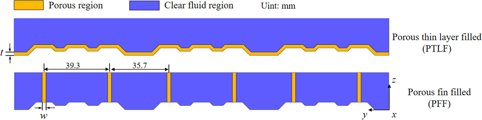
Metal foam filling method (yz-plane).
Geometrical parameters of two partially filled models at different filling rates
| V p (%) | t/(mm) | w/(mm) |
|---|---|---|
| 5.55 | 1 | 2.28 |
| 11.1 | 2 | 4.56 |
| 16.6 | 3 | 6.84 |
| 22.2 | 4 | 9.12 |
This study considers the effect of the filling rate on the flow and heat transfer characteristics of the channel and compares the flow and heat transfer performance of aluminum and copper foam channels under different porosities (φ) and pore densities (ω). The ranges of porosity and pore density for the samples are from 0.903 to 0.956 and from 10 to 40 PPI, respectively. Table 2 lists the geometrical parameters of the metal foam samples. The naming of the samples in Table 2 is consistent with the studies of Mancin et al. [21,22,23]. Taking sample Al-10-4.4 as an example, Al represents the material of the sample, 10 indicates a pore density of 10 PPI, and 4.4 denotes a relative density (ρ p) of 4.4%, where the sum of ρ p and porosity (φ) is 1.
| Sample | Pore density ω (PPI) | Porosity φ | Area per unit volume a sf (m2/m3) | Fiber thickness d f (mm) | Permeability K (10−7 m2) | Inertia coefficient (C f) |
|---|---|---|---|---|---|---|
| Al-10-4.4 | 10 | 0.956 | 537 | 0.445 | 1.82 | 0.102 |
| Al-10-6.6 | 10 | 0.934 | 692 | 0.450 | 1.87 | 0.082 |
| Al-10-9.7 | 10 | 0.903 | 839 | 0.529 | 1.90 | 0.074 |
| Al-20-6.8 | 20 | 0.932 | 1,156 | 0.367 | 0.824 | 0.065 |
| Al-40-7.0 | 40 | 0.930 | 1,679 | 0.324 | 0.634 | 0.086 |
| Cu-10-6.7 | 10 | 0.933 | 698 | 0.390 | 2.09 | 0.091 |
| Cu-10-9.5 | 10 | 0.905 | 831 | 0.403 | 1.21 | 0.056 |
| Cu-20-6.7 | 20 | 0.933 | 1,148 | 0.293 | 0.41 | 0.039 |
| Cu-40-6.6 | 40 | 0.934 | 1,635 | 0.262 | 0.44 | 0.060 |
2.2 Governing equations and computational methods
The air flow in the channel is assumed to be incompressible, steady turbulent flow. The effects of gravity and radiation are not considered. The metal foam is assumed to be homogeneous, isotropic porous medium. The thermal resistance between the panel surface and the porous structure is neglected. The continuity, momentum, and energy equations in the clear fluid region of the channel are as follows [24]:
where the subscript f denotes the fluid; u i is the velocity component in the ith direction; T is the temperature; ρ, μ, λ, and c p are the density, kinetic viscosity, thermal conductivity, and specific heat capacity, respectively; Prt is the turbulence Prandtl number with a value of 0.85; and μ t is the turbulent viscosity.
The standard k-ε turbulence model is used to solve the turbulence flow in both the porous and clear fluid regions. The transport equations for the turbulent kinetic energy (k) and turbulent dissipation rate (ε) are as follows [25]:
where turbulent kinetic energy generation term G k and the turbulent viscosity μ t are defined as follows:
The constants C 1ε , C 2ε , C μ , σ k , and σ ε in Eqs. (4) and (5) are set as follows:
In the porous region, the Forchheimer–Brinkman model is adopted as momentum equation and the local thermal non-equilibrium model is used as energy equation. The governing equations are as follows [26]:
where Eq. (9) is the momentum equation for the porous region and the last term on the right-hand side of the equation represents the resistance to flow through the porous region. Eqs. (10) and (11) are the energy equations for the fluid and solid domains in the porous region, respectively, with the last term on the right-hand side representing the heat transfer between the metal skeleton and the internal fluid. The subscript s denotes the solid. C f, K, h sf, and a sf are the inertia coefficient, permeability, surface heat transfer coefficient of solid skeleton, and area per unit volume of metal foam, respectively. λ fe and λ se are the effective thermal conductivity of fluid and metallic skeleton in porous region, respectively, and μ eff is the effective viscosity. h sf, λ fe, λ se, and μ eff can be derived from the equations in ref. [26] as follows:
The velocity distribution at the inlet is uniform, and the temperature is 303.15 K. Pressure boundary condition is applied at the outlet. Symmetric boundary condition is used on the plane of y = 0 and z = H/2. The temperature distribution (T x,y ) on the panel surface follows the distribution proposed by Garelli et al. [5], as shown in Eq. (15), which was numerically solved by Rodriguez et al. [27] for the conjugate heat transfer process of the panel, and it has also been validated by the experiments. No-slip condition is applied to the channel walls. Moreover, momentum and heat flux conservation conditions are adopted between the porous region and the clear fluid region [9]. The aforementioned governing equations and boundary conditions are solved iteratively with finite volume method using the commercial software Fluent. Pressure and velocity coupling are achieved using Coupled algorithm. To ensure computational accuracy, the convection terms in the momentum, energy, turbulent kinetic energy, and turbulent dissipation rate equations are discretized using the second-order upwind scheme. The residuals for the continuity, momentum, and turbulence equations are set to 10−5, and the residual for the energy equation is set to 10−9.
In this study, other parameters are defined as follows:
Hydraulic diameter:
Reynolds number [28]:
where u m is the average inlet velocity.
Darcy friction factor [28]:
where Δp and L are the pressure drop and channel length of the test section, respectively.
Nusselt number [28]:
where the convective heat transfer coefficient h of the heated wall is defined as follows:
where m is the inlet mass flow rate; T in and T out are the averaged inlet and outlet temperatures, respectively; and A f is the heat transfer area.
To evaluate the overall heat transfer performance of the metal foam-filled channels, the performance evaluation criterion (PEC) is used, which is defined as follows [28]:
where Nu0 and f 0 represent the average Nusselt number and friction factor for the smooth channel, respectively. It can be seen that PEC is a comprehensive evaluation index of heat transfer enhancement effect and pumping power loss cost. When PEC is larger than 1, the positive benefit of heat transfer enhancement can be achieved, indicating that the heat transfer enhancement is larger than the cost of pumping power loss.
3 Grid independence test and model validations
3.1 Grid independence test
To ensure the accuracy of the numerical simulation, the computational mesh is tested for grid independence. A 3D hybrid mesh, consisting of hexahedral, polyhedral, and prismatic cells, is generated using Fluent Meshing software. The mesh is refined at the near-wall and porous interfaces, as shown in Figure 3. In the case of PFF with the metal foam sample Al-10-4.4 and fin width of 4.56 mm, six grid sets are tested to assess grid independence, using the Nu and f as evaluation targets. As shown in Figure 4, it is found that the relative deviation in Nu and f under grid with 8,118,446 elements is only 1.4 and 0.7%, respectively, compared with the grid of 11,654,793 elements. Therefore, it can be concluded that the grid with 8,118,446 elements is sufficient to obtain the grid-independent results, and this grid set is adopted for the following studies.

Computational grid.

Variations of Nu and f at different computational grids (Re = 5,125).
3.2 Model validations
To validate the accuracy of the numerical model and computational method, the model validation is carried out. First, the radial dimensionless velocity variation in the metal foam partially filled channel is verified. As shown in Figure 5(a), the computational results of the dimensionless velocity along the dimensionless height of the channel are in good agreement with the simulation results of Kotresha and Gnanasekaran [26]. Subsequently, a comparison is also conducted with the experimental results of Mancin et al. [21,22,23], where channels are fully filled with aluminum and copper metal foams of different porosities and pore densities. The computational pressure drop per unit length can also agree well with the experimental results, as shown in Figure 5(b), where the Cu-20-6.7 case shows a larger deviation as compared with the other two cases, and the average deviation for Cu-20-6.7 case is 6.36%.

(a) Comparison of dimensionless velocity and (b) comparison of pressure drop.
Moreover, the accuracy of the heat transfer results is also verified. Figure 6(a) presents the experimental results of fully filled uniform porous media of Mancin et al. [22,23]. Comparing the average wall temperatures for aluminum foam and copper foam fully filled channels with different porosities and pore densities, it shows that the simulation results of present study are in good agreement with the experimental results. The Al-10-4.4 case shows a relatively larger deviation than other cases, and its average deviation is 8.10%. Additionally, a comparison is also conducted with the simulation results of partially filled gradient metal foam of Jadhav et al. [9], as shown in Figure 6(b). The radial temperature of fluid in the metal foam partially filled tube is validated, and the computational results are in good agreement with the simulations of Jadhav et al. [9]. In summary, the numerical model and computational method used in this study are reliable, which can be used for the subsequent analysis of flow and heat transfer characteristics of metal foam partially filled channels.

(a) Comparison of averaged wall temperature and (b) comparison of fluid radial temperature distribution.
4 Results and discussion
Figure 7 demonstrates the local velocity distribution in PTLF and PFF channels at the yz-plane (x = 762 mm) for different filling rates. It shows that the air velocity is higher in the clear fluid region as compared with the porous region. Compared with the PTLF channel, the interface area between the porous fins and the fluid is larger in the PFF channel, which will lead to greater fluid permeation inside the porous region. As the filling rate increases, the air velocity in the clear fluid region increases, while the proportion of low-speed fluid within the porous region increases. It is attributed to the high flow resistance in the porous region, which will lead most of the fluid flow into the clear fluid region. Meanwhile, the average velocity at the porous interface (u interface) indicates that as the filling rate increases, the fluid permeation within the porous region of the PTLF channel increases significantly, while in the PFF channel, the variation is small. At the same filling rate, the width of the porous fin in the PFF channel is obviously larger than the thickness of the porous thin layer. Consequently, the permeation resistance within the porous fins will restrict the increase of fluid permeation.

Local velocity distributions at the yz-plane (x = 762 mm) in PTLF and PFF channels (Re = 10,250, Al-10-9.7): (a) V p = 11.1% and (b) V p = 22.2%.
Figure 8 illustrates the local turbulence kinetic energy distribution in PTLF and PFF channels at the yz-plane (x = 762 mm) for different filling rates. It shows that the local turbulence kinetic energy is higher at the porous interface, while it is relatively low at other regions. As described by Chandesris et al. [29], large flow velocity differences at the porous interfaces and the presence of solid matrix inside porous region will induce Kelvin–Helmholtz instabilities, where vortices generation and dissipation are remarkable. Compared with the PTLF channel, the maximum turbulence kinetic energy (k max) at the porous interface in the PFF channel is larger. In conjunction with Figure 7, it can be seen that this is due to the large velocity difference between inside and outside of porous region in the PFF channel. Furthermore, as the filling rate increases, the turbulence effects at the porous interface become more pronounced, which is due to the increased velocity difference between the porous and clear regions.

Local turbulence kinetic energy distributions at the yz-plane (x = 762 mm) in PTLF and PFF channels (Re = 10,250, Al-10-9.7): (a) V p = 11.1% and (b) V p = 22.2%.
Figure 9 presents the local fluid temperature distribution in PTLF and PFF channels at the yz-plane (x = 762 mm) for different filling rates. Compared with the PTLF channel, the PFF channel has a higher average temperature (T avg) and a smaller maximum temperature difference (ΔT max) at the cross-section, indicating better flow mixing and heat transfer capabilities. This is attributed to the larger interface area between porous fins and clear fluid regions, as well as the enhanced turbulence intensity at the porous interface. As the filling rate increases, the average temperature of the channel cross-section, T avg, increases for both filling methods, which is due to the increased heat transfer area within the porous region and the enhanced turbulence intensity at the interfaces.

Local fluid temperature distributions at the yz-plane (x = 762 mm) in PTLF and PFF channels (Re = 10,250, Al-10-9.7): (a) V p = 11.1% and (b) V p = 22.2%.
Figure 10 illustrates the variations of the average heat flux (q w) on the heating surface and the temperature difference between the inlet and outlet (ΔT) with Reynolds number (Re) in PTLF and PFF channels at different filling rates. As shown in Figure 10(a), when Re increases, the temperature difference in the PTLF channel changes little. However, the temperature difference in the PFF channel changes greatly, which is larger than that in the PTLF channel at the same filling ratio. The metal foam fins in the PFF channel can go deep into the middle of the channel, to exchange heat with the cold fluid. In contrast, the metal foam plate in the PTLF channel only exchanges heat with the near-wall cold fluid and has a limited effect on the center fluid. As shown in Figure 10(b), when Re increases, the average heat flux will increase on the heating surface in both PTLF and PFF channels, indicating heat transfer improvement. Additionally, the effect of filling rate is more remarkable on temperature difference and heat flux in the PTLF channel, whereas it is relatively small for the PFF channel. This is due to relatively small variation of fluid permeation in the porous region of PFF channel as filling rate changes. Therefore, increasing filling rate can effectively enhance heat transfer in the PTLF channel, while it has less effect on the PFF channel.

Variations of temperature difference between inlet and outlet and heat flux on the heating wall with Re in PTLF and PFF channels (Al-10-9.7): (a) ΔT and (b) q w.
Figure 11 illustrates the variations of Nusselt number (Nu), friction factor (f), and PEC with Re for both PTLF and PFF channels. As Re increases, Nu increases in both channels, the variation of f in the PTLF channel is small, while f decreases in the PFF channel. This is due to the small spacing between porous fins, where the flow boundary layer between two fins may interact with each other, and the f in the PFF channel would be more sensitive as Re changes. When the filling rate increases, both Nu and f increase in PTLF and PFF channels, indicating an increase in both heat transfer performance and flow resistance. As porous region increases in the channel, the heat transfer surface area is larger within the metal foam, together with more fibers, which would lead to higher heat transfer performance and flow resistance. The impact of V p on Nu in PFF channels is small compared with the PTLF channels. The previous analyses indicate that the fluid permeability in the porous region of the PFF channel changes little as V p changes. Therefore, the heat transfer enhancement is not obvious. Furthermore, difference in the f is also observed at different V p in the PFF channels. It is noted that the f for the case of V p = 22.2% is much higher than that of other cases. This is potentially due to the reduced spacing between adjacent porous fins at this filling rate, and it may lead to mutual interference of flow boundary layers. When compared with both the PTLF channels and unfilled channels, PFF channels demonstrate higher Nu and f values, which should be related to the factors, such as the interfacial area between porous and clear fluid regions, fluid permeation rate in the porous region, and turbulence intensity at the interfaces. In summary, the overall heat transfer performance of PFF channels is generally better than that of PTLF channels. The PEC of PTLF channels increases with V p, while the PEC of PFF channels changes little with V p. It is noted that the PEC of PFF channel with V p = 11.1% is generally higher than those of the PTLF channels and PFF channels at other filling rates. Although the PTLF channel with V p = 22.2% exhibits slightly higher PEC values at high Re, its metal foam usage is twice that in the PFF channel with V p = 11.1%. Within the range of Re = 5,125–15,375, compared with the PTLF channel under V p = 11.1%, the Nu, f, and PEC of the PFF channel under V p = 11.1% are increased by 37.5–82.6%, 85.2–172.0%, and 12.0–30.8%, respectively, and its PEC value is from 2.07 to 2.16.

Variations of Nu, f, and PEC with Re in PTLF and PFF channels (Al-10-9.7): (a) Nu, (b) f, and (c) PEC.
4.1 Effect of porosity and pore density of metal foams on flow and heat transfer in PFF channel
4.1.1 Effect of porosity
Figure 12 presents the local velocity distributions at the yz-plane (x = 762 mm) in PFF channels (V p = 11.1%), where the metal foams have different porosities (φ) but the same pore density (ω). In aluminum foam PFF channels, fluid permeation in the porous region increases as φ decreases. In contrast, for copper foam PFF channels, fluid permeation decreases as φ decreases. The fluid permeation in the porous region is directly related to the sample’s permeability. The higher permeability, the lower flow resistance in the porous region, and the higher fluid permeation. As indicated in Table 2, under the same pore density conditions, the permeability of aluminum metal foam increases as φ decreases, while the opposite trend is observed for copper metal foam. The difference in permeability between the cases of Al-10-6.6 and Al-10-9.7 is small, which would lead to similar velocity distributions at the cross-section of different channels. Furthermore, the permeability of both metal foam materials varies with φ. According to Mancin et al. [21], an increase in φ will lead to a reduction in solid material in the aluminum foam, decrease fiber thickness, and potentially change the fiber cross-section from circular to triangular shape. Such changes in the fiber cross-section may introduce additional resistance and reduce the permeability.

Local fluid temperature distributions at the yz-plane (x = 762 mm) in PFF channels under different porosities (Re = 10,250).
Figure 13 illustrates the variations of Nusselt number (Nu), friction factor (f), and PEC with Reynolds number (Re) in PFF channels (V p = 11.1%) under different porosity rates (φ) but certain pore density (ω). It is observed that as Re increases, Nu increases while f decreases. As shown in Figure 13(a), when φ decreases, the Nu of the PFF channel increases for both aluminum and copper foams. Since the area per unit volume of the metal foam skeleton (a sf) will increase as φ decreases, which would be beneficial for the heat transfer in porous region. Conversely, the fluid permeation in the porous region of the copper foam PFF channel will decrease as φ decreases, which will weaken the heat transfer in the porous region. The results indicate that the effect of a sf on the heat transfer is more significant than the effect of permeability K. In the range of Re = 5,125–15,375, with the same ω, the Nu for the case of Cu-10-6.7 is increased by 4.6–11.2% as compared with the case of Al-10-6.6, while for the case of Cu-10-9.5, it is increased by 3.9–9.4% as compared with the case of Al-10-9.7, which is benefited from copper’s higher thermal conductivity. As shown in Figure 13(b), it is found that f decreases when φ decreases in the aluminum foam PFF channel, while it increases in the copper foam PFF channel, which is due to the permeability of the metal foams. The higher the permeability, the lower the flow resistance in the porous region and the lower the total flow resistance in the channel. As shown in Table 2, the permeability of the aluminum foam samples increases when φ decreases under the same ω, while this trend is reversed for copper foam. Furthermore, due to the similar permeability of the aluminum foams, the flow resistance differences among different aluminum foam PFF channels are small. As shown in Figure 13(c), in the range of Re = 5,125–15,375, when Re increases, the PEC in copper foam PFF channels increases, while that in aluminum foam PFF channels increases first and then decreases slightly. At high Re, the variations of PEC for the cases of Al-10-6.6 and Al-10-9.7 are small, while the variation of PEC for the case of Al-10-4.4 is remarkable. When φ decreases, the PEC in both aluminum foam and copper foam PFF channels increases, and the variation of PEC in the aluminum foam PFF channel is more obvious. Overall, in the range of Re = 5,125–15,375, the PEC in the copper foam PFF channel is larger as compared with that in the aluminum foam PFF channel, and the Al-10-9.7 and Cu-10-9.5 samples are the best samples among the two metal foam materials at the same ω, where the PEC values of Al-10-9.7 and Cu-10-9.5 are 2.07-2.16 and 2.12-2.32, respectively. Compared with the Al-10-9.7 PFF channel, the PEC in the Cu-10-9.5 PFF channel is increased by 2.4–7.4%.

Variations of Nu, f, and PEC with Re in PFF channel channels under different porosities: (a) Nu, (b) f, and (c) PEC.
4.1.2 Effect of pore density
Figure 14 illustrates the variations of Nusselt number (Nu), friction factor (f), and PEC in PFF channels (V p = 11.1%) with Re under similar porosity (φ) and different pore densities (ω). It is observed that as Re increases, Nu increases while f decreases. As shown in Figure 14(a), when ω increases, the Nu of the PFF channel increases for both aluminum and copper foams. This is due to the area per unit volume of the metal foam sample, a sf, which is positively correlated with ω, as shown in Table 2. In the range of Re = 5,125–15,375, with similar φ, as ω increases from 10 to 40 PPI, the Nu in copper PFF channels will increase by 4.6–11.2%, 3.0–11.1%, and 3.5–10.8% as compared with aluminum PFF channels. Figure 14(b) shows that, among copper PFF channels, the PFF channel filled with Cu-10-6.7 sample has the smallest pressure drop, and the other two samples show small differences. In the aluminum foam PFF channels, f increases as ω increases, which is also related to the permeability of the metal foams, as shown in Table 2. Overall, in the range of Re = 5,125–15,375, PFF channels filled with Cu-10-6.7 and Al-10-6.6 foams have the smallest flow resistance. As compared with those filled with Cu-20-6.7 and Al-40-7 foams, the f of Cu-10-6.7 and Al-10-6.6 foams are decreased by 10.7–12.4% and 8.7–9.5%, respectively. Figure 14(c) indicates that, in copper PFF channels, the PFF channel filled with Cu-10-6.7 foam can achieve the maximum PEC at low Re, while the PFF channel filled with Cu-40-6.6 foam can achieve the maximum PEC at relatively high Re. In the aluminum foam PFF channel, the PEC increases with pore density. Overall, as compared with aluminum foam PFF channels, copper foam PFF channels would have better overall heat transfer performance. The Al-40-7 and Cu-40-6.6 foams are the best samples among the two types of metal foams, respectively. Under similar φ, in the range of Re = 5,125–15,375, the PEC values of Al-40-7 and Cu-40-6.6 foams are 2.02-2.11 and 2.09-2.29, respectively. Compared with the PFF channels filled with Al-40-7, the PEC of the PFF channel filled with Cu-40-6.6 is increased by 3.5–8.5%.

Variations of Nu, f, and PEC with Re in PFF channels under different pore densities: (a) Nu, (b) f, and (c) PEC.
4.2 Comparison with previous work
Due to the limited research on heat transfer enhancement at the air side of panel-type radiator, and since the heat exchange channels of solar air heaters are similar to the models studied here, which can be regarded as closed rectangular channels, the findings of the present study on air-side closed channel flow and heat transfer are compared with those in the field of heat transfer enhancement for solar air heaters. Figure 15 shows a comparison of the present results with those from previous research under optimal conditions for the variations of PEC in the channel with Re. Enhanced heat transfer measures in the related studies include miniature and dimple combination [30], inclined trapezoidal vortex generators [20], multi-row vortex generator [31], perforated-winglet-type vortex generator [32], hole-punched wings [33], quarter-circular ribs [34], multi-V-shaped baffle [35], and wavy-groove and perforated-delta wing combination [36]. The PFF channels of Cu-10-9.5 and Al-10-9.7 (V p = 11.1%) in this study are selected for the comparison. When Re is low, the PEC in the PFF channel of this study is slightly lower than that in the channel with combined wavy-groove and perforated-delta wing as reported in Skullong et al. [36], but it is still higher than that in the other heat transfer enhancement channels. At high Re, the overall heat transfer performance of this study is significantly improved as compared with the previous studies.

Comparison of present study with previous relevant studies.
5 Conclusions
In this study, the flow and heat transfer characteristics of copper and aluminum metal foams in the air-side closed channel of panel-type radiator for transformers are numerically investigated. The effects of the PTLF and PFF methods of metal foams and the filling rate V p are analyzed, and the variations of the flow and heat transfer in the channel for different metal foam materials, porosities (φ), and pore densities (ω) are discussed. The main conclusions are as follows:
Compared with the PTLF channel, the fluid permeation in the porous region and the maximum turbulent kinetic energy k max at the porous interface of the PFF channel are larger, so the flow mixing and heat transfer in the PFF channel are better. As the filling rate V p increases, the heat transfer area in the porous region increases, and the turbulence intensity at the porous interface is enhanced, which can promote the flow mixing and heat transfer.
In the range of Re = 5,125–15,375, the PFF channel has larger Nu and f, which are less affected by V p as compared with the PTLF and unfilled channels. The overall heat transfer performance (PEC) in the PFF channel is generally better than that in the PTLF channel at the same V p. Compared with the PTLF channel, the Nu, f, and PEC in the PFF channel are increased by 37.5–82.6%, 85.2–172.0%, and 12.0–30.8%, respectively, and the PEC values of the PFF channel are in the range of 2.07–2.16, when Al-10-9.7 sample is used as filling material and V p = 11.1%.
With the same pore density, as the porosity decreases, the area per unit volume of the metal foam a sf increases and the Nu in the PFF channels increases. The flow resistance within the channels is related to the permeability of the metal foam samples. The PEC in the PFF channels increases as metal foam porosity decreases, and the PEC is higher in the copper foam PFF channels as compared with the aluminum foam PFF channels. In the range of Re = 5,125–15,375, when V p = 11.1%, the PEC in Cu-10-9.5 PFF channels is increased by 2.4–7.4% as compared with Al-10-9.7 PFF channels.
With similar porosity rates, as the pore density increases, the Nu in the PFF channels increases. The flow resistance in the Cu-10-6.7 and Al-10-6.6 PFF channels is the smallest. Compared with the aluminum foam PFF channels, the copper foam PFF channels have better overall heat transfer performance. In the range of Re = 5,125–15,375, when V p = 11.1%, the PEC in Cu-40-6.6 PFF channels is increased by 3.5–8.5% as compared with Al-40-7 PFF channels.
-
Funding information: This work was supported by the S &T Project of State Grid Shanghai Municipal Electrical Power Company under Grant Number 52094023000F.
-
Author contributions: All authors have accepted responsibility for the entire content of this manuscript and approved its submission.
-
Conflict of interest: The authors state no conflict of interest.
-
Data availability statement: The data that support the findings of this study are available from the corresponding author upon reasonable request.
References
[1] Kim M, Cho SM, Kim JK. Prediction and evaluation of the cooling performance of radiators used in oil-filled power transformer applications with non-direct and direct-oil-forced flow. Exp Therm Fluid Sci. 2013;44:392–7.10.1016/j.expthermflusci.2012.07.011Search in Google Scholar
[2] Bracale A, Carpinelli G, Pagano M, Falco PD. A probabilistic approach for forecasting the allowable current of oil-Immersed transformers. IEEE Trans Power Deliv. 2018;33(4):1825–34.10.1109/TPWRD.2018.2791181Search in Google Scholar
[3] Taghikhani Z, Taghikhani MA, Gharehpetian GB. A comprehensive investigation on the efficiency of alumina nanoparticles in ONAN and OFAN cooling performance enhancement of transformers. Powder Technol. 2021;387:466–80.10.1016/j.powtec.2021.04.031Search in Google Scholar
[4] Tian Y, Si W, Fu C, Tian Y, Yuan P, Yang J, et al. Numerical study on hydrodynamic and heat transfer performances for panel-type radiator of transformer using the chimney effect. Chem Eng Trans. 2023;103:163–8.Search in Google Scholar
[5] Garelli L, Ríos Rodriguez G, Dorella JJ, Storti MA. Heat transfer enhancement in panel type radiators using delta-wing vortex generators. Int J Therm Sci. 2019;137:64–74.10.1016/j.ijthermalsci.2018.10.037Search in Google Scholar
[6] Li YG, Zhou ZR, Lin BR, Zhang H, Huo WF, Deng HL, et al. Analysis of external heat dissipation enhancement of oil-immersed transformer based on falling film measure. Therm Sci. 2022;26(6):4519–33.10.2298/TSCI211015041LSearch in Google Scholar
[7] Paramane SB, Joshi K, Veken WVD, Sharma A. CFD study on thermal performance of radiators in a power transformer: effect of blowing direction and offset of fans. IEEE Trans Power Deliv. 2014;29(6):2596–604.10.1109/TPWRD.2014.2347292Search in Google Scholar
[8] Kim YJ, Jeong M, Park YG, Ha MY. A numerical study of the effect of a hybrid cooling system on the cooling performance of a large power transformer. Appl Therm Eng. 2018;136:275–86.10.1016/j.applthermaleng.2018.03.019Search in Google Scholar
[9] Jadhav PH, Gnanasekaran N, Mobedi M. Analysis of functionally graded metal foams for the accomplishment of heat transfer enhancement under partially filled condition in a heat exchanger. Energy. 2023;263:125691.10.1016/j.energy.2022.125691Search in Google Scholar
[10] Noh JS, Lee KB, Lee CG. Pressure loss and forced convective heat transfer in an annulus filled with aluminum foam. Int Commun Heat Mass Transf. 2006;33(4):434–44.10.1016/j.icheatmasstransfer.2005.11.003Search in Google Scholar
[11] Leong KC, Li HY, Jin LW, Chai JC. Numerical and experimental study of forced convection in graphite foams of different configurations. Appl Therm Eng. 2010;30(5):520–32.10.1016/j.applthermaleng.2009.10.014Search in Google Scholar
[12] Lu W, Zhang T, Yang M. Analytical solution of forced convective heat transfer in parallel-plate channel partially filled with metallic foams. Int J Heat Mass Transf. 2016;100:718–27.10.1016/j.ijheatmasstransfer.2016.04.047Search in Google Scholar
[13] Anuar FS, Abdi IA, Hooman K. Flow visualization study of partially filled channel with aluminium foam block. Int J Heat Mass Transf. 2018;127:1197–211.10.1016/j.ijheatmasstransfer.2018.07.047Search in Google Scholar
[14] Jadhav PH, Gnanasekaran N, Perumal DA, Mobedi M. Performance evaluation of partially filled high porosity metal foam configurations in a pipe. Appl Therm Eng. 2021;194:117081.10.1016/j.applthermaleng.2021.117081Search in Google Scholar
[15] Jiang Y, Feng Y, Zhang S, Qin J, Bao W. Numerical heat transfer analysis of transcritical hydrocarbon fuel flow in a tube partially filled with porous media. Open Phys. 2016;14(1):659–67.10.1515/phys-2016-0073Search in Google Scholar
[16] Alfellag MA, Ahmed HE, Jehad MG, Hameed M. Assessment of heat transfer and pressure drop of metal foam-pin-fin heat sink. Int J Therm Sci. 2021;170:107109.10.1016/j.ijthermalsci.2021.107109Search in Google Scholar
[17] Akbarnataj K, Hamidpour MR, Shirani E, Salimpour MR. Optimization of porous finned heat exchanger configuration using the comprehensive performance methodology. Int Commun Heat Mass Transf. 2022;138:106318.10.1016/j.icheatmasstransfer.2022.106318Search in Google Scholar
[18] Salehi A, Fattahi A. A numerical investigation of hydrogen impingement-effusion array jet for a heat sink cooling using solid/porous fins: A thermo-hydrodynamic analysis. Int J Hydrog Energy. 2024;52:381–96.10.1016/j.ijhydene.2023.05.257Search in Google Scholar
[19] Min C, Jin J, Wang X, Qi C. Numerical investigation of natural convection heat transfer for panel type radiator mounted with longitudinal vortex generators. ICMREE 2011: Proceedings of the 2011 International Conference on Materials for Renewable Energy and Environment; 2011 May 20–22. Shanghai, China, New York: IEEE; 2011. p. 1267–70.10.1109/ICMREE.2011.5930567Search in Google Scholar
[20] Xiao H, Dong Z, Liu Z, Liu W. Heat transfer performance and flow characteristics of solar air heaters with inclined trapezoidal vortex generators. Appl Therm Eng. 2020;179:115484.10.1016/j.applthermaleng.2020.115484Search in Google Scholar
[21] Mancin S, Zilio C, Cavallini A, Rossetto L. Pressure drop during air flow in aluminum foams. Int J Heat Mass Transf. 2010;53(15):3121–30.10.1016/j.ijheatmasstransfer.2010.03.015Search in Google Scholar
[22] Mancin S, Zilio C, Cavallini A, Rossetto L. Heat transfer during air flow in aluminum foams. Int J Heat Mass Transf. 2010;53(21):4976–84.10.1016/j.ijheatmasstransfer.2010.05.033Search in Google Scholar
[23] Mancin S, Zilio C, Diani A, Rossetto L. Experimental air heat transfer and pressure drop through copper foams. Exp Therm Fluid Sci. 2012;36:224–32.10.1016/j.expthermflusci.2011.09.016Search in Google Scholar
[24] Yu C, Zhang H, Wang Y, Wang J, Gao B, Fang Z. Comparative study of the thermal performance of four different parallel flow shell and tube heat exchangers with different performance indicators. Open Phys. 2020;18(1):1121–35.10.1515/phys-2020-0202Search in Google Scholar
[25] Kotresha B, Gnanasekaran N. Numerical simulations of fluid flow and heat transfer through aluminum and copper metal foam heat exchanger-a comparative study. Heat Transf Eng. 2020;41(6–7):637–49.10.1080/01457632.2018.1546969Search in Google Scholar
[26] Kotresha B, Gnanasekaran N. Investigation of mixed convection heat transfer through metal foams partially filled in a vertical channel by using computational fluid dynamics. J Heat Transf-Trans ASME. 2018;140(11):112501.10.1115/1.4040614Search in Google Scholar
[27] Rodriguez GR, Garelli L, Storti M, Granata D, Amadei M, Rossetti M. Numerical and experimental thermo-fluid dynamic analysis of a power transformer working in ONAN mode. Appl Therm Eng. 2017;112:1271–80.10.1016/j.applthermaleng.2016.08.171Search in Google Scholar
[28] Dogan M. Abir İgci A. An experimental comparison of delta winglet and novel type vortex generators for heat transfer enhancement in a rectangular channel and flow visualization with stereoscopic PIV. Int J Heat Mass Transf. 2021;164:120592.10.1016/j.ijheatmasstransfer.2020.120592Search in Google Scholar
[29] Chandesris M, D’Hueppe A, Mathieu B, Jamet D, Goyeau B. Direct numerical simulation of turbulent heat transfer in a fluid-porous domain. Phys Fluids. 2013;25(12):125110.10.1063/1.4851416Search in Google Scholar
[30] Arya N, Goel V, Sunden B. Solar air heater performance enhancement with differently shaped miniature combined with dimple shaped roughness: CFD and experimental analysis. Sol Energy. 2023;250:33–50.10.1016/j.solener.2022.12.024Search in Google Scholar
[31] Karkaba H, Russeil S, Simo Tala JV, Bougeard D, Boonaert J, Etienne L, et al. Effect of using multiple vortex generator rows on heat transfer enhancement inside an asymmetrically heated rectangular channel. Appl Therm Eng. 2023;227:120359.10.1016/j.applthermaleng.2023.120359Search in Google Scholar
[32] Skullong S, Promthaisong P, Promvonge P, Thianpong C, Pimsarn M. Thermal performance in solar air heater with perforated-winglet-type vortex generator. Sol Energy. 2018;170:1101–17.10.1016/j.solener.2018.05.093Search in Google Scholar
[33] Promvonge P, Skullong S. Heat transfer augmentation in solar receiver heat exchanger with hole-punched wings. Appl Therm Eng. 2019;155:59–69.10.1016/j.applthermaleng.2019.03.132Search in Google Scholar
[34] Mahanand Y, Senapati JR. Thermo-hydraulic performance analysis of a solar air heater (SAH) with quarter-circular ribs on the absorber plate: A comparative study. Int J Therm Sci. 2021;161:106747.10.1016/j.ijthermalsci.2020.106747Search in Google Scholar
[35] Tamna S, Skullong S, Thianpong C, Promvonge P. Heat transfer behaviors in a solar air heater channel with multiple V-baffle vortex generators. Sol Energy. 2014;110:720–35.10.1016/j.solener.2014.10.020Search in Google Scholar
[36] Skullong S, Promvonge P, Thianpong C, Pimsarn M. Thermal performance in solar air heater channel with combined wavy-groove and perforated-delta wing vortex generators. Appl Therm Eng. 2016;100:611–20.10.1016/j.applthermaleng.2016.01.107Search in Google Scholar
© 2025 the author(s), published by De Gruyter
This work is licensed under the Creative Commons Attribution 4.0 International License.
Articles in the same Issue
- Research Articles
- Single-step fabrication of Ag2S/poly-2-mercaptoaniline nanoribbon photocathodes for green hydrogen generation from artificial and natural red-sea water
- Abundant new interaction solutions and nonlinear dynamics for the (3+1)-dimensional Hirota–Satsuma–Ito-like equation
- A novel gold and SiO2 material based planar 5-element high HPBW end-fire antenna array for 300 GHz applications
- Explicit exact solutions and bifurcation analysis for the mZK equation with truncated M-fractional derivatives utilizing two reliable methods
- Optical and laser damage resistance: Role of periodic cylindrical surfaces
- Numerical study of flow and heat transfer in the air-side metal foam partially filled channels of panel-type radiator under forced convection
- Water-based hybrid nanofluid flow containing CNT nanoparticles over an extending surface with velocity slips, thermal convective, and zero-mass flux conditions
- Dynamical wave structures for some diffusion--reaction equations with quadratic and quartic nonlinearities
- Solving an isotropic grey matter tumour model via a heat transfer equation
- Study on the penetration protection of a fiber-reinforced composite structure with CNTs/GFP clip STF/3DKevlar
- Influence of Hall current and acoustic pressure on nanostructured DPL thermoelastic plates under ramp heating in a double-temperature model
- Applications of the Belousov–Zhabotinsky reaction–diffusion system: Analytical and numerical approaches
- AC electroosmotic flow of Maxwell fluid in a pH-regulated parallel-plate silica nanochannel
- Interpreting optical effects with relativistic transformations adopting one-way synchronization to conserve simultaneity and space–time continuity
- Modeling and analysis of quantum communication channel in airborne platforms with boundary layer effects
- Theoretical and numerical investigation of a memristor system with a piecewise memductance under fractal–fractional derivatives
- Tuning the structure and electro-optical properties of α-Cr2O3 films by heat treatment/La doping for optoelectronic applications
- High-speed multi-spectral explosion temperature measurement using golden-section accelerated Pearson correlation algorithm
- Dynamic behavior and modulation instability of the generalized coupled fractional nonlinear Helmholtz equation with cubic–quintic term
- Study on the duration of laser-induced air plasma flash near thin film surface
- Exploring the dynamics of fractional-order nonlinear dispersive wave system through homotopy technique
- The mechanism of carbon monoxide fluorescence inside a femtosecond laser-induced plasma
- Numerical solution of a nonconstant coefficient advection diffusion equation in an irregular domain and analyses of numerical dispersion and dissipation
- Numerical examination of the chemically reactive MHD flow of hybrid nanofluids over a two-dimensional stretching surface with the Cattaneo–Christov model and slip conditions
- Impacts of sinusoidal heat flux and embraced heated rectangular cavity on natural convection within a square enclosure partially filled with porous medium and Casson-hybrid nanofluid
- Stability analysis of unsteady ternary nanofluid flow past a stretching/shrinking wedge
- Solitonic wave solutions of a Hamiltonian nonlinear atom chain model through the Hirota bilinear transformation method
- Bilinear form and soltion solutions for (3+1)-dimensional negative-order KdV-CBS equation
- Solitary chirp pulses and soliton control for variable coefficients cubic–quintic nonlinear Schrödinger equation in nonuniform management system
- Influence of decaying heat source and temperature-dependent thermal conductivity on photo-hydro-elasto semiconductor media
- Dissipative disorder optimization in the radiative thin film flow of partially ionized non-Newtonian hybrid nanofluid with second-order slip condition
- Bifurcation, chaotic behavior, and traveling wave solutions for the fractional (4+1)-dimensional Davey–Stewartson–Kadomtsev–Petviashvili model
- New investigation on soliton solutions of two nonlinear PDEs in mathematical physics with a dynamical property: Bifurcation analysis
- Mathematical analysis of nanoparticle type and volume fraction on heat transfer efficiency of nanofluids
- Creation of single-wing Lorenz-like attractors via a ten-ninths-degree term
- Optical soliton solutions, bifurcation analysis, chaotic behaviors of nonlinear Schrödinger equation and modulation instability in optical fiber
- Chaotic dynamics and some solutions for the (n + 1)-dimensional modified Zakharov–Kuznetsov equation in plasma physics
- Fractal formation and chaotic soliton phenomena in nonlinear conformable Heisenberg ferromagnetic spin chain equation
- Single-step fabrication of Mn(iv) oxide-Mn(ii) sulfide/poly-2-mercaptoaniline porous network nanocomposite for pseudo-supercapacitors and charge storage
- Novel constructed dynamical analytical solutions and conserved quantities of the new (2+1)-dimensional KdV model describing acoustic wave propagation
- Tavis–Cummings model in the presence of a deformed field and time-dependent coupling
- Spinning dynamics of stress-dependent viscosity of generalized Cross-nonlinear materials affected by gravitationally swirling disk
- Design and prediction of high optical density photovoltaic polymers using machine learning-DFT studies
- Robust control and preservation of quantum steering, nonlocality, and coherence in open atomic systems
- Coating thickness and process efficiency of reverse roll coating using a magnetized hybrid nanomaterial flow
- Dynamic analysis, circuit realization, and its synchronization of a new chaotic hyperjerk system
- Decoherence of steerability and coherence dynamics induced by nonlinear qubit–cavity interactions
- Finite element analysis of turbulent thermal enhancement in grooved channels with flat- and plus-shaped fins
- Modulational instability and associated ion-acoustic modulated envelope solitons in a quantum plasma having ion beams
- Statistical inference of constant-stress partially accelerated life tests under type II generalized hybrid censored data from Burr III distribution
- On solutions of the Dirac equation for 1D hydrogenic atoms or ions
- Entropy optimization for chemically reactive magnetized unsteady thin film hybrid nanofluid flow on inclined surface subject to nonlinear mixed convection and variable temperature
- Stability analysis, circuit simulation, and color image encryption of a novel four-dimensional hyperchaotic model with hidden and self-excited attractors
- A high-accuracy exponential time integration scheme for the Darcy–Forchheimer Williamson fluid flow with temperature-dependent conductivity
- Novel analysis of fractional regularized long-wave equation in plasma dynamics
- Development of a photoelectrode based on a bismuth(iii) oxyiodide/intercalated iodide-poly(1H-pyrrole) rough spherical nanocomposite for green hydrogen generation
- Investigation of solar radiation effects on the energy performance of the (Al2O3–CuO–Cu)/H2O ternary nanofluidic system through a convectively heated cylinder
- Quantum resources for a system of two atoms interacting with a deformed field in the presence of intensity-dependent coupling
- Studying bifurcations and chaotic dynamics in the generalized hyperelastic-rod wave equation through Hamiltonian mechanics
- A new numerical technique for the solution of time-fractional nonlinear Klein–Gordon equation involving Atangana–Baleanu derivative using cubic B-spline functions
- Interaction solutions of high-order breathers and lumps for a (3+1)-dimensional conformable fractional potential-YTSF-like model
- Hydraulic fracturing radioactive source tracing technology based on hydraulic fracturing tracing mechanics model
- Numerical solution and stability analysis of non-Newtonian hybrid nanofluid flow subject to exponential heat source/sink over a Riga sheet
- Numerical investigation of mixed convection and viscous dissipation in couple stress nanofluid flow: A merged Adomian decomposition method and Mohand transform
- Effectual quintic B-spline functions for solving the time fractional coupled Boussinesq–Burgers equation arising in shallow water waves
- Analysis of MHD hybrid nanofluid flow over cone and wedge with exponential and thermal heat source and activation energy
- Solitons and travelling waves structure for M-fractional Kairat-II equation using three explicit methods
- Impact of nanoparticle shapes on the heat transfer properties of Cu and CuO nanofluids flowing over a stretching surface with slip effects: A computational study
- Computational simulation of heat transfer and nanofluid flow for two-sided lid-driven square cavity under the influence of magnetic field
- Irreversibility analysis of a bioconvective two-phase nanofluid in a Maxwell (non-Newtonian) flow induced by a rotating disk with thermal radiation
- Hydrodynamic and sensitivity analysis of a polymeric calendering process for non-Newtonian fluids with temperature-dependent viscosity
- Exploring the peakon solitons molecules and solitary wave structure to the nonlinear damped Kortewege–de Vries equation through efficient technique
- Modeling and heat transfer analysis of magnetized hybrid micropolar blood-based nanofluid flow in Darcy–Forchheimer porous stenosis narrow arteries
- Activation energy and cross-diffusion effects on 3D rotating nanofluid flow in a Darcy–Forchheimer porous medium with radiation and convective heating
- Insights into chemical reactions occurring in generalized nanomaterials due to spinning surface with melting constraints
- Influence of a magnetic field on double-porosity photo-thermoelastic materials under Lord–Shulman theory
- Soliton-like solutions for a nonlinear doubly dispersive equation in an elastic Murnaghan's rod via Hirota's bilinear method
- Analytical and numerical investigation of exact wave patterns and chaotic dynamics in the extended improved Boussinesq equation
- Nonclassical correlation dynamics of Heisenberg XYZ states with (x, y)-spin--orbit interaction, x-magnetic field, and intrinsic decoherence effects
- Exact traveling wave and soliton solutions for chemotaxis model and (3+1)-dimensional Boiti–Leon–Manna–Pempinelli equation
- Unveiling the transformative role of samarium in ZnO: Exploring structural and optical modifications for advanced functional applications
- On the derivation of solitary wave solutions for the time-fractional Rosenau equation through two analytical techniques
- Analyzing the role of length and radius of MWCNTs in a nanofluid flow influenced by variable thermal conductivity and viscosity considering Marangoni convection
- Advanced mathematical analysis of heat and mass transfer in oscillatory micropolar bio-nanofluid flows via peristaltic waves and electroosmotic effects
- Exact bound state solutions of the radial Schrödinger equation for the Coulomb potential by conformable Nikiforov–Uvarov approach
- Some anisotropic and perfect fluid plane symmetric solutions of Einstein's field equations using killing symmetries
- Nonlinear dynamics of the dissipative ion-acoustic solitary waves in anisotropic rotating magnetoplasmas
- Curves in multiplicative equiaffine plane
- Exact solution of the three-dimensional (3D) Z2 lattice gauge theory
- Propagation properties of Airyprime pulses in relaxing nonlinear media
- Symbolic computation: Analytical solutions and dynamics of a shallow water wave equation in coastal engineering
- Wave propagation in nonlocal piezo-photo-hygrothermoelastic semiconductors subjected to heat and moisture flux
- Comparative reaction dynamics in rotating nanofluid systems: Quartic and cubic kinetics under MHD influence
- Laplace transform technique and probabilistic analysis-based hypothesis testing in medical and engineering applications
- Physical properties of ternary chloro-perovskites KTCl3 (T = Ge, Al) for optoelectronic applications
- Gravitational length stretching: Curvature-induced modulation of quantum probability densities
- The search for the cosmological cold dark matter axion – A new refined narrow mass window and detection scheme
- A comparative study of quantum resources in bipartite Lipkin–Meshkov–Glick model under DM interaction and Zeeman splitting
- PbO-doped K2O–BaO–Al2O3–B2O3–TeO2-glasses: Mechanical and shielding efficacy
- Nanospherical arsenic(iii) oxoiodide/iodide-intercalated poly(N-methylpyrrole) composite synthesis for broad-spectrum optical detection
- Sine power Burr X distribution with estimation and applications in physics and other fields
- Numerical modeling of enhanced reactive oxygen plasma in pulsed laser deposition of metal oxide thin films
- Dynamical analyses and dispersive soliton solutions to the nonlinear fractional model in stratified fluids
- Computation of exact analytical soliton solutions and their dynamics in advanced optical system
- An innovative approximation concerning the diffusion and electrical conductivity tensor at critical altitudes within the F-region of ionospheric plasma at low latitudes
- An analytical investigation to the (3+1)-dimensional Yu–Toda–Sassa–Fukuyama equation with dynamical analysis: Bifurcation
- Swirling-annular-flow-induced instability of a micro shell considering Knudsen number and viscosity effects
- Numerical analysis of non-similar convection flows of a two-phase nanofluid past a semi-infinite vertical plate with thermal radiation
- MgO NPs reinforced PCL/PVC nanocomposite films with enhanced UV shielding and thermal stability for packaging applications
- Optimal conditions for indoor air purification using non-thermal Corona discharge electrostatic precipitator
- Investigation of thermal conductivity and Raman spectra for HfAlB, TaAlB, and WAlB based on first-principles calculations
- Tunable double plasmon-induced transparency based on monolayer patterned graphene metamaterial
- DSC: depth data quality optimization framework for RGBD camouflaged object detection
- A new family of Poisson-exponential distributions with applications to cancer data and glass fiber reliability
- Numerical investigation of couple stress under slip conditions via modified Adomian decomposition method
- Monitoring plateau lake area changes in Yunnan province, southwestern China using medium-resolution remote sensing imagery: applicability of water indices and environmental dependencies
- Heterodyne interferometric fiber-optic gyroscope
- Exact solutions of Einstein’s field equations via homothetic symmetries of non-static plane symmetric spacetime
- A widespread study of discrete entropic model and its distribution along with fluctuations of energy
- Empirical model integration for accurate charge carrier mobility simulation in silicon MOSFETs
- The influence of scattering correction effect based on optical path distribution on CO2 retrieval
- Anisotropic dissociation and spectral response of 1-Bromo-4-chlorobenzene under static directional electric fields
- Role of tungsten oxide (WO3) on thermal and optical properties of smart polymer composites
- Analysis of iterative deblurring: no explicit noise
- 10.1515/phys-2025-0251
- Review Article
- Examination of the gamma radiation shielding properties of different clay and sand materials in the Adrar region
- Erratum
- Erratum to “On Soliton structures in optical fiber communications with Kundu–Mukherjee–Naskar model (Open Physics 2021;19:679–682)”
- Special Issue on Fundamental Physics from Atoms to Cosmos - Part II
- Possible explanation for the neutron lifetime puzzle
- Special Issue on Nanomaterial utilization and structural optimization - Part III
- Numerical investigation on fluid-thermal-electric performance of a thermoelectric-integrated helically coiled tube heat exchanger for coal mine air cooling
- Special Issue on Nonlinear Dynamics and Chaos in Physical Systems
- Analysis of the fractional relativistic isothermal gas sphere with application to neutron stars
- Abundant wave symmetries in the (3+1)-dimensional Chafee–Infante equation through the Hirota bilinear transformation technique
- Successive midpoint method for fractional differential equations with nonlocal kernels: Error analysis, stability, and applications
- Novel exact solitons to the fractional modified mixed-Korteweg--de Vries model with a stability analysis