Modeling and analysis of quantum communication channel in airborne platforms with boundary layer effects
-
Zhi-Feng Deng
 and
Lei Shi
and
Lei Shi

Abstract
The establishment of secure global communication links is fundamentally dependent on the support of airborne platforms. However, the transmission of quantum signals from these platforms faces significant challenges related to boundary layer (BL) effects. This article presents an improved channel loss calculation model that effectively incorporates these BL effects in airborne environment. The model takes into account detailed variations in beam width, scintillation index, and transmission efficiency within the airborne environment. The results indicate that BL effects have an impact on the beam width and scintillation index, highlighting the need to maximize the receiver aperture within payload capacity constraints. In addition, the analysis shows that the supersonic BL results in greater losses and higher error rates compared to the transonic BL. Furthermore, atmospheric turbulence is identified as the primary factor that reduces transmission efficiency when transmitting over long distances in the airborne environment.
1 Introduction
In recent years, the field of secure communications has seen a growing interest in quantum communication, which is based on the principles of quantum mechanics and has made significant progress over the past decade [1–3]. However, it has become evident that fiber-optic quantum communication cannot achieve ultra-long distance communication without ground relays. Furthermore, due to geographical constraints, global quantum communication cannot be achieved by ground-based relays alone [4,5]. Consequently, the use of airborne platforms is a potential way to overcome the distance limitations of quantum communication and thus enable a global quantum network [6,7].
Airborne quantum communication systems are strategically valuable for secure military and emergency communications, offering advantages such as high security, high maneuverability, and low latency [6–8]. A significant amount of research and experimental works on airborne quantum key distribution (QKD) have been reported [9–11]. Nauerth et al. successfully integrated a BB84 system into an airborne platform, enabling air-to-ground QKD experiments [9]. Wang et al. conducted experiments on a floating moving platform to investigate the feasibility of QKD using entanglement states [10]. Pugh et al. conducted QKD experiments between an aircraft and an optical ground station utilizing a quantum up link, with experimental error rates ranging from 2.66 to 5.08% [11]. These results provide a technical basis for the practical implementation of airborne quantum communication platforms. However, in both free-space optical and quantum communication systems, atmospheric turbulence is an unavoidable problem [12–16]. Moreover, when the speed of the aircraft exceeds 0.3 Mach, the geometry of the optical window can lead to the formation of complex turbulent flows. As the optical signal traverses the flow field, boundary layer (BL) effects such as optical distortion and interference occur.
The investigation of BL effects in airborne laser systems has become crucial [17–24]. The Airborne Aero-Optics Laboratory has conducted experiments on transonic plane window turntables to study the BL effect of outer pod windows under high-speed flight conditions [17–19]. Smith et al. conducted an analysis of the optical distortion caused by turbulence at flight speeds of 0.4 to 0.6 Ma, thereby confirming the frozen flow hypothesis of the BL [20]. Morrida et al. investigated the influence of shockwaves and wakes generated by conical windows and planar windows on the laser beam when the Mach number between 0.5 and 0.8 Ma [21]. Sun et al. investigated the simulation and verification methods of aero-optic effects in supersonic turbulent BLs, demonstrating that numerical coding and appropriate grid scales are effective for both turbulence and aero-optic statistical results [22]. Zhao et al. conducted flight experiments in the BL, with a particular focus on the potential of lens compensation to counteract detector defocus caused by the BL [23]. Dang et al. proposed a method to reduce dynamic aberrations by designing the inner surface of a conformal dome [24]. Similarly, in the context of airborne quantum communication, the BL introduces a degree of random offsets and jitter to the transmitted photons, which has the potential to disrupt their modes. Previous studies have analyzed the performance of BL effects on QKD systems in airborne environments, covering air-to-ground, air-to-air, satellite-to-aircraft, as well as measured supersonic BLs [25–28]. However, these studies often overlook the significant influence of the BL and do not fully consider the general conditions of atmospheric turbulence in airborne communication links.
In this article, the influence of atmospheric turbulence and BL effects on quantum channels in the airborne environment is comprehensively investigated. In Section 2, the BL effects of the airborne platform are introduced, and the relevant formulas for the beam width caused by the BL effects are derived. In Section 3, the model of typical atmospheric turbulence effects is introduced, and the BL effects are incorporated into the typical atmospheric turbulence model. In Section 4, the corresponding estimation results for beam width, scintillation index, and transmission efficiency are presented. By considering the combined influence of BL effects and atmospheric turbulence, this work provides a reference for the design and optimization of airborne quantum communication systems in real scenarios.
2 Channel model
The airborne platform plays a key role in the integrated quantum communication network, serving as both a receiver for satellite signals and a transmitter to establish temporary communication with ground stations, as illustrated in Figure 1. When a moving airborne platform is incorporated into the communication system, the BL is formed around the optical window surface of the airborne platform. The substantial reduction in received intensity and signal loss can be attributed to atmospheric turbulence along the propagation path and the BL surrounding the aircraft. The present study is concerned with the air-to-ground communication scenario, in which the BL exerts an influence on the transmitter.

Schematic diagram of the quantum network based on the airborne platform. (a) Satellite to aircraft, (b) air to air, and (c) air to ground.
2.1 Effects of aero-optical BL
The BL surrounding a moving aircraft is typically confined to a few centimeters near the fuselage. Consequently, it can be modeled using a phase screen. The phase screen is characterized by the Kolmogorov spectral model of refractive index fluctuations, with the refractive index structure constant

Schematic diagram of the transmitted photons in the airborne environment. The black dashed lines represent the transmitted beams affected only by diffraction effects, and the red line represents the transmitted beam under the combined effect of the BL and atmospheric turbulence.
2.1.1 Beam broadening
In the airborne environment, considering the scintillation caused by atmospheric turbulence and BL effects, the long-distance transmission beam radius expressions under the condition of weak and strong fluctuations are obtained, respectively, as follows [29]:
where
where the broadening coefficients
where
Clear 1 model [31]
| Altitude (km) |
|
|---|---|
|
|
|
|
|
|
|
|
|
|
|
|
2.2 Beam width and scintillation index
2.2.1 Scintillation index
The scintillation index of the Gaussian beam at the receiving end in the direction of the optical axis can be obtained according to Rytov theory in the case of weak turbulence and the Kolmogorov spectrum model [32] by considering the influence of the BL effects as follows:
where
For moderate-to-strong turbulence conditions, the scintillation index along the optical axis can be expressed by the Gamma–Gamma model:
where
Eq. (6) is valid when the receiving aperture is smaller than the Fresnel scale or the spatial coherence length. When the aperture at the receiving end is a fixed length D, the scintillation index can be expressed as follows:
where
where
2.2.2 Strehl ratio
The Strehl ratio is a measure of the on-axis beam intensity at the target (far field receiver) relative to the intensity for a perfect on-axis intensity at the target. It is calculated by dividing the on-axis beam intensity
where
There are various methods to calculate OPD. In experimental settings, the most commonly used wavefront aberration measurement methods include Malley probes, Shack–Hartmann sensors, small aperture beam techniques, sensors based on Background Oriented Schlieren-based wavefront sensing, and nano-tracer-based planar laser scattering [34,35]. In a simulation, the corresponding flow field is typically obtained using computational fluid dynamics (CFD) software, and then the OPD is calculated using ray tracing methods [36]. The density distribution of a flow field determines its optical refractive properties, and the density distribution is not directly applicable to optical calculations. The interface between fluid dynamics and optics is the Gladstone–Dale equation [25]:
where
Based on extensive data,
where
where
2.3 Channel transmittance models
In a previous study [39–41], the mathematical expression for the free-space quantum communication channel was presented, with the transmittance
The systematic effects encompass predictable physical processes that disrupt and attenuate the signal. These effects include the refraction of the beam in different atmospheric layers and the reduction of light due to absorption or scattering by air molecules or aerosols. When the zenith angle is below
In examining the effect of random atmospheric turbulence, it is possible to select from a range of statistical probability distributions, with a specific choice depending on the intensity of the turbulence. In situations where turbulence is relatively weak, the log-normal (LN) probability distribution is a suitable option [44], expressed as follows:
The
On the other hand, the moderate-to-strong turbulence condition is the consequence of both large-scale and small-scale fluctuations, which can be modeled using a Gamma–Gamma distribution for the
where
The
In free-space quantum communication, the width of the optical beam increases as it propagates over distances of tens to hundreds of kilometers. A reduction in beam size requires higher precision for the pointing and tracking mechanisms. This is of particular importance in the context of quantum communication, given that the smaller footprint of the beam significantly reduces losses when received through a finite-aperture telescope. Furthermore, mechanical errors in the tracking and pointing systems, as well as vibrations of the airborne platform, can lead to random beam jitter, resulting in fluctuation losses. In the case of a Gaussian beam, the normalized spatial distribution of the emission intensity at a distance L from the transmitter is given by the following equation [46]:
where
Assuming a circular receiving telescope aperture with an opening area
where
where
To ascertain the probability density function of
where
In airborne quantum communication systems, the photon transmission efficiency
The overall transmission efficiency, accounting for BL effects, can be determined as follows:
From Eq. (28), it can be seen that the first statistical moment of
where
where
where
3 Simulation results
3.1 Parameters setting
In this section, we focus on the beam broadening caused by BL effects in the airborne environment, the increase in beam width, scintillation index, and the corresponding changes in transmission efficiency. It is worth noting that, for computational convenience, the eigenvalues of the statistical components are considered when estimating the transmission efficiency, with a primary focus on the BL effects. Given the detailed aircraft description with 0.7 Ma velocity, the BL will be generated around the hemisphere-on-cylinder turret and its refractive index distribution can be calculated by Eqs (11) and (12), shown in Figure 3. The relevant parameters are presented in Table 2.

Cross section of the evaluated refractive index distribution of the hemisphere-on-cylinder turret.
Parameters of airborne QKD
| Category | Parameter | Description | Value |
|---|---|---|---|
| BL |
|
Flight speed | 0.8 Ma/1.5 Ma |
|
|
BL thickness | 0.025 m | |
|
|
Air density | 0.525 kg/m
|
|
|
|
Modelling parameters | 0.34/0.7 | |
|
|
Skin friction coefficient | 0.0026 | |
| Atmosphere turbulence |
|
Refractive index | CLEAR 1 model [31] |
|
|
Deterministic attenuation | 0.75 | |
| Photon source |
|
Waist radius | 0.05 m |
|
|
Transmitter wavelength | 1,550 mm | |
|
|
Fried parameter in zenith | 0.2 m | |
| Receiver |
|
Diameter of the receiver telescope | 0.3 m |
|
|
system detection error rate | 0.01 | |
| Protocol |
|
Intensity of signal states | 0.8 |
|
|
Intensity of decoy states | 0.1 | |
|
|
System repetition rate | 100 MHz | |
|
|
Sent probability of signal states | 0.5 | |
|
|
Sent probability of decoy states | 0.25 | |
|
|
Sent probability of vacuum states | 0.25 |
3.2 Beam width and scintillation index
By employing Eqs (1)–(3) and substituting the relevant parameters, it is feasible to determine the curve between the beam radius of the transmitted beam in the airborne environment and the transmission distance for varying wavelengths and altitudes, as illustrated in Figure 4. For longer transmission distances, the BL effects result in a greater degree of beam broadening for the 1,060 nm beam compared to the 1,550 nm beam. Furthermore, the results show that as the transmission distance increases, the beam radius continues to expand. When the altitude is maintained at a constant value, the beam with a wavelength of 1,550 nm exhibits a greater transmitted beam radius than the 1,060 nm beam. Conversely, as shown in Figure 4(b), when the wavelength is maintained at a constant value, an increase in altitude results in a reduction in the size of the transmitted beam radius. It is worth noting that the beam radius with the BL effects is larger than that observed in the absence of such effects. Therefore, in the engineering practice of quantum communications on airborne platforms, it is advisable to consider the combined effects of the BL and atmospheric turbulence on beam radius. This can be achieved by using a beacon beam with a shorter wavelength to mitigate the impact of these effects.
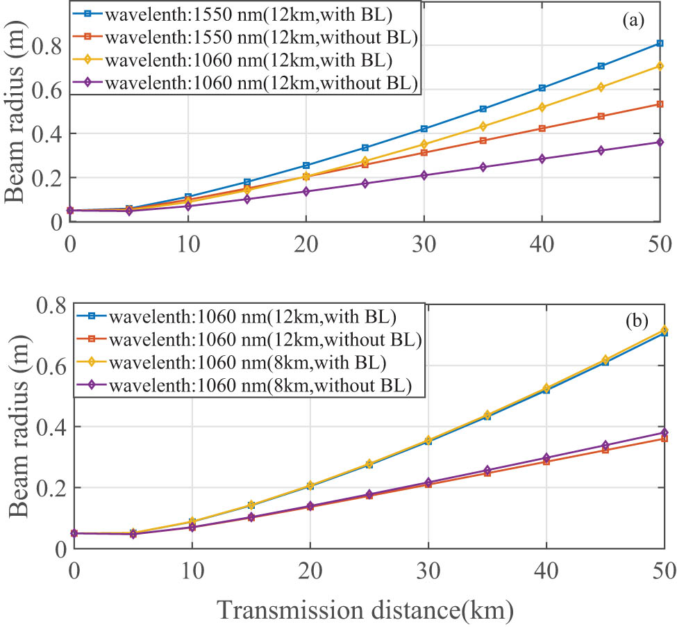
The beam radius varies with the transmission distance at different altitudes and wavelengths: (a) the same altitudes and (b) the same wavelength.
Figure 5 presents the scintillation index varying with the transmission distance in an airborne environment. It can be observed that as the transmission distance increases, the scintillation index also increases. At the same altitude, the increase in the scintillation index to the transmission distance is relatively smaller for the 1,550 nm wavelength compared to the 1,060 nm wavelength. Similarly, at an altitude of 12 km, the increase in the scintillation index relative to the transmission distance is less pronounced than at an altitude of 8 km. Additionally, the BL effects cause an increase in the scintillation index under the same conditions, with the largest increase occurring at 12 km and 1,550 nm.

The scintillation index varies with the transmission distance at different altitudes and wavelengths: (a) the same altitudes and (b) the same wavelength.
In the airborne environment, the payload capacity of the aircraft platform limits the capabilities of the communications system, especially when the aircraft platform serves as the receiving end. In such scenarios, the size of the receiving telescope will impose limitations on its capabilities. Accordingly, it is essential to examine the variation of the scintillation index with transmission distance for diverse receiving apertures, as illustrated in Figure 6. For the same receiving aperture, it can be seen that lower altitudes result in higher scintillation indices. Similarly, at the same altitude, larger receiving apertures lead to smaller scintillation indices. Furthermore, considering the overall performance of the system, it can be advised that larger receiving apertures should be used within the payload capacity of the airborne platform.
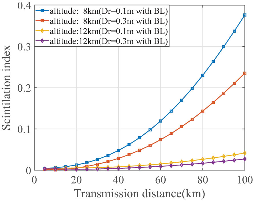
The scintillation index varies with transmission distance at different altitudes and diameters of the receiver.
3.3 Transmission efficiency
In Figure 7, the curve between the transmission efficiency of the system in the airborne environment and the transmission distance can be quantified for different receiver apertures. It can be seen that an increase in transmission distance is accompanied by a gradual decrease in transmission efficiency. When the level of BL effects remains constant, a reduction in the size of the receiving aperture results in a more rapid decline in transmission efficiency, even if the transmission distance remains unchanged. It can be concluded that larger receiving apertures can maintain a higher transmission efficiency, which is consistent with the results for the beam radius. Figure 7(b) presents a comparison of transmission efficiency and receiving aperture with and without the BL effects. It can be seen that the transmission efficiency continues to improve as the receiving aperture increases. At this point, altitude is not the main factor for affecting transmission efficiency, and the BL becomes dominant.

The transmission efficiency varies with (a) transmission distance and (b) diameter of the receiver.
Figure 8 shows the curve between the transmission efficiency of a beam in the airborne environment and the transmission distance under the influence of varying intensities of BL effects (expressed as the ratio of

The transmission efficiency varies with transmission distance.
By incorporating the calculated transmission efficiency into the vacuum and weak decoy BB84 protocol and using the given parameters, it is feasible to calculate the total transmission loss and the QBER value of the system as the transmission distance increases, as shown in Figure 9. It can be observed that the total loss due to the hemisphere-on-cylinder turret and the QBER trend are essentially the same as in the case of the scaling argument. Furthermore, under supersonic conditions, the system initially experiences significant losses due to BL effects, although this is not significantly reflected in the QBER. As the transmission distance increases, the rate of loss increase is initially relatively slow. However, after a certain transmission distance is reached, both the transmission loss and the QBER value increase rapidly. The influence of the supersonic BL (OPD/
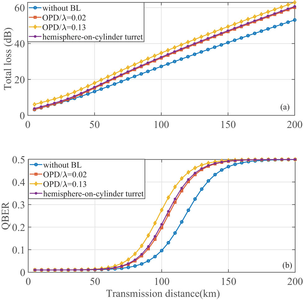
The performance varies with transmission distance: (a) the total loss and (b) the QBER.
4 Conclusion
This article presents an improved channel loss calculation model that incorporates BL effects in airborne environment. By incorporating scaling arguments, this model facilitates the rapid implementation of adaptive compensation for BL effects. Modeling the BL as a thin phase screen allows the derivation of beam width and scintillation index under the combined effects of atmospheric turbulence and BL. The results show that the BL has a significant effect on the beam width, highlighting the importance of selecting the largest possible receiving aperture within the constraints of payload capacity. Subsequently, the flow field around the hemisphere-on-cylinder turret was simulated using CFD and compared with scaling arguments. Furthermore, an investigation of QBER was also carried out using the decoy-state BB84 protocol, showing that BL effects consistently reducing transmission efficiency, with a more pronounced reduction observed at higher altitudes. The analysis also shows that the supersonic BL results in greater losses and higher error rates compared to the transonic BL. While atmospheric turbulence has been identified as a primary factor in the reduction of transmission efficiency, it is important to recognize the significant impact of BL effects, which deserves considerable attention. Overall, our results provide valuable technical support for the implementation of airborne quantum communication.
Acknowledgments
The authors acknowledge the support by the National Natural Science Foundation of China (Grants No. 61971436, No. 62401621), the Natural Science Basic Research Plan in Shaanxi Province of China (Grant No. 2023JC-QN-0674).
-
Funding information: This work was supported by the National Natural Science Foundation of China (Grants No. 61971436, No. 62401621), the Natural Science Basic Research Plan in Shaanxi Province of China (Grant No. 2023JCQN-0674).
-
Author contributions: Zhi-Feng Deng: Writing – original draft, Software, Methodology, Formal analysis, Data curation. Hao-Ran Hu: Supervision, Project administration, Investigation. Ya Wang: Visualization, Validation, Conceptualization. Jia-Hao Li: Resources, Data curation, Investigation. Jia-Hua Wei: Data curation, Conceptualization. Validation. Hui-Cun Yu: Writing – review & editing, Supervision, Funding acquisition. Lei Shi: Writing – review & editing, Supervision, Funding acquisition. All authors have accepted responsibility for the entire content of this manuscript and approved its submission.
-
Conflict of interest: The authors state no conflict of interest.
-
Data availability statement: The datasets generated and/or analysed during the current study are available from the corresponding author on reasonable request.
References
[1] Lu CY, Cao Y, Peng CZ, Pan JW. Micius quantum experiments in space. Rev Mod Phys. 2022;94:035001. 10.1103/RevModPhys.94.035001Search in Google Scholar
[2] Liu HY, Tian XH, Gu C, Fan P, Ni X, Yang R, et al. Drone-based entanglement distribution towards mobile quantum networks. Natl Sci Rev. 2020;7(5):921–8. 10.1093/nsr/nwz227Search in Google Scholar PubMed PubMed Central
[3] Mehic M, Niemiec M, Rass S, Ma J, Peev M, Aguado A, et al. Quantum key distribution: a networking perspective. ACM Comput Surv. 2020;53(1):1–41. 10.1145/3402192Search in Google Scholar
[4] Shen Q, Guan JY, Ren JG, Zeng T, Hou L, Li M, et al. 113 km free-space time-frequency dissemination at the 19th decimal instability. 2022. arXiv: http://arXiv.org/abs/arXiv:2203.11272. Search in Google Scholar
[5] Wang BX, Mao Y, Shen L, Zhang L, Lan XB, Ge D, et al. Long-distance transmission of quantum key distribution coexisting with classical optical communication over a weakly-coupled few-mode fiber. Opt Express. 2020;28(9):12558–65. 10.1364/OE.388857Search in Google Scholar PubMed
[6] Xue Y, Chen W, Wang S, Yin Z, Shi L, Han Z. Airborne quantum key distribution: a review. Chin Opt Lett. 2021;19(12):122702. 10.3788/COL202119.122702Search in Google Scholar
[7] Dubey U, Bhole P, Dutta A, Behera DP, Losu V, Pandeeti GS, et al. A review on practical challenges of aerial quantum communication. Phys Open. 2024;19:100210. 10.1016/j.physo.2024.100210Search in Google Scholar
[8] Quintana C, Sibson P, Erry G, Thueux Y, Kingston E, Ismail T, et al. Low size, weight and power quantum key distribution system for small form unmanned aerial vehicles. In: Free-Space Laser Communications XXXI. Vol. 10910. Bellingham, Washington, USA: SPIE; 2019. p. 240–6. 10.1117/12.2507669Search in Google Scholar
[9] Nauerth S, Moll F, Rau M, Horwath J, Frick S, Fuchs C, et al. Air to ground quantum key distribution. In: Quantum Communications and Quantum Imaging X. Vol. 8518. Bellingham, Washington, USA: SPIE; 2012. p. 71–6. 10.1117/12.929790Search in Google Scholar
[10] Wang JY, Yang B, Liao SK, Zhang L, Shen Q, Hu XF, et al. Direct and full-scale experimental verifications towards ground-satellite quantum key distribution. Nat Photonics. 2013;7(5):387–93. 10.1038/nphoton.2013.89Search in Google Scholar
[11] Pugh CJ, Kaiser S, Bourgoin JP, Jin J, Sultana N, Agne S, et al. Airborne demonstration of a quantum key distribution receiver payload. Quantum Sci Technol. 2017;2(2):024009. 10.1088/2058-9565/aa701fSearch in Google Scholar
[12] Elsayed EE. Atmospheric turbulence mitigation of MIMO-RF/FSO DWDM communication systems using advanced diversity multiplexing with hybrid N-SM/OMI M-ary spatial pulse-position modulation schemes. Opt Commun. 2024;562:130558. 10.1016/j.optcom.2024.130558Search in Google Scholar
[13] Elsayed EE, Hayal MR, Nurhidayat I. Coding techniques for diversity enhancement of dense wavelength division multiplexing MIMO-FSO fault protection protocols systems over atmospheric turbulence channels. IET Optoelectron. 2024;18(1–2):11–31. 10.1049/ote2.12111Search in Google Scholar
[14] Elsayed EE. Performance enhancement of atmospheric turbulence channels in DWDM-FSO PON communication systems using M-ary hybrid DPPM-M-PAPM modulation schemes under pointing errors, ASE noise and interchannel crosstalk. J Opt. 2024;30:1–17. 10.1007/s12596-024-01908-9Search in Google Scholar
[15] Yousif BB, Elsayed EE, Alzalabani MM. Atmospheric turbulence mitigation using spatial mode multiplexing and modified pulse position modulation in hybrid RF/FSO orbital-angular-momentum multiplexed based on MIMO wireless communications system. Opt Commun. 2019;436:197–208. 10.1016/j.optcom.2018.12.034Search in Google Scholar
[16] Elsayed EE. Investigations on modified OOK and adaptive threshold for wavelength division multiplexing free-space optical systems impaired by interchannel crosstalk, atmospheric turbulence, and ASE noise. J Opt. 2024;30:1–14. 10.1007/s12596-024-01929-4Search in Google Scholar
[17] Porter C, Gordeyev S, Zenk M, Jumper E. Flight measurements of aero-optical distortions from a flat-windowed turret on the airborne aero-optics laboratory (AAOL). In: 42nd AIAA Plasmadynamics and Lasers Conference. 2011. p. 3280. 10.2514/6.2011-3280Search in Google Scholar
[18] Jumper EJ, Gordeyev S, Cavalieri D, Rollins P, Whiteley M, Krizo M. Airborne aero-optics laboratory-transonic (AAOL-T). In: 53rd AIAA Aerospace Sciences Meeting. 2015. p. 0675. 10.2514/6.2015-0675Search in Google Scholar
[19] Kalensky M, Gordeyev S, Jumper EJ. In-flight studies of aero-optical distortions around AAOL-BC. In: AIAA Aviation 2019 Forum. 2019. p. 3253. 10.2514/6.2019-3253Search in Google Scholar
[20] Smith A, Gordeyev S, Jumper E. Aperture effects on aero-optical distortions caused by subsonic boundary layers. In: 43rd AIAA Plasmadynamics and Lasers Conference. 2012. p. 2986. 10.2514/6.2012-2986Search in Google Scholar
[21] Morrida J, Gordeyev S, De Lucca N, Jumper EJ. Shock-related effects on aero-optical environment for hemisphere-on-cylinder turrets at transonic speeds. Appl Opt. 2017;56(17):4814–24. 10.1364/AO.56.004814Search in Google Scholar PubMed
[22] Sun XW, Yang XL, Liu W. Validation method of aero-optical effect simulation for supersonic turbulent boundary layer. AIAA J. 2021;59(2):410–6. 10.2514/1.J059583Search in Google Scholar
[23] Zhao HW, Hou TJ, Zhu B, Deng M. Design analysis for optical dome and scanning mirror. J Appl Opt. 2010;6:898–903. Search in Google Scholar
[24] Dang F, Chen S, Zhang W, Wang H, Fan Z. Optimized design method for the inner surface of a conformal dome based on the ray tracing approach. Appl Opt. 2017;56(28):8230–39. 10.1364/AO.56.008230Search in Google Scholar PubMed
[25] Yu HC, Tang BY, Chen H, Xue Y, Tang J, Yu WR, et al. Airborne quantum key distribution with boundary layer effects. EPJ Quantum Technol. 2021;8:1–13. 10.1140/epjqt/s40507-021-00115-wSearch in Google Scholar
[26] Yu H, Tang B, Li J, Cao Y, Zhou H, Li S, et al. Satellite-to-aircraft quantum key distribution performance estimation with boundary layer effects. Chin Opt Lett. 2023;21(4):042702. 10.3788/COL202321.042702Search in Google Scholar
[27] Yu H, Tang B, Ding H, Xue Y, Tang J, Wang X, et al. Airborne quantum key distribution performance analysis under supersonic boundary layer. Entropy. 2023;25(3):472. 10.3390/e25030472Search in Google Scholar PubMed PubMed Central
[28] Deng Z, Yu H, Tang J, Li J, Cao Y, Hu H, et al. Air-to-air quantum key distribution with boundary layer effects. Results Phys. 2023;54:107020. 10.1016/j.rinp.2023.107020Search in Google Scholar
[29] Zhao J, Zhao SH, Zhao WH, Cai J, Liu Y, Li X. BER performance analysis of M-ary PPM over exponentiated Weibull distribution for airborne laser communications. J Opt Technol. 2017;84(11):658–63. 10.1364/JOT.84.000658Search in Google Scholar
[30] Andrews LC, Phillips RL. Laser beam propagation through random media. Bellingham, Washington: SPIE Press; 2005. 10.1117/3.626196Search in Google Scholar
[31] Zhao J, Zhao SH, Zhao WH, Li YJ, Liu Y, Li X. Analysis of link performance and robustness of homodyne BPSK for airborne backbone laser communication system. Opt Commun. 2016;359:189–94. 10.1016/j.optcom.2015.09.082Search in Google Scholar
[32] Andrews LC, Phillips RL, Wayne D, Sauer P, Leclerc T, Crabbs R. Creating a Cn2 profile as a function of altitude using scintillation measurements along a slant path. In: High Energy/Average Power Lasers and Intense Beam Applications VI; Atmospheric and Oceanic Propagation of Electromagnetic Waves VI. Vol. 8238. Bellingham, Washington, USA: SPIE; 2012:95–106. 10.1117/12.913756Search in Google Scholar
[33] Ross TS. Limitations and applicability of the Maréchal approximation. Appl Opt. 2009;48(10):1812–8. 10.1364/AO.48.001812Search in Google Scholar
[34] Zhao X, Yi S, Ding H. Experimental study on the influence of attitude angle on the aero-optical effects of a hypersonic optical dome. Optik. 2020;201:163448. 10.1016/j.ijleo.2019.163448Search in Google Scholar
[35] Ding H, Yi S, Zhu Y, He L. Experimental investigation on aero-optics of supersonic turbulent boundary layers. Appl Opt. 2017;56(26):7604–10. 10.1364/AO.56.007604Search in Google Scholar PubMed
[36] Wang M, Mani A, Gordeyev S. Physics and computation of aero-optics. Annu Rev Fluid Mech. 2012;44:299–321. 10.1146/annurev-fluid-120710-101152Search in Google Scholar
[37] Wyckham CM, Smits AJ. Aero-optic distortion in transonic and hypersonic turbulent boundary layers. AIAA J. 2009;47(9):2158–68. 10.2514/1.41453Search in Google Scholar
[38] Kalensky M, Jumper EJ, Gordeyev S. Extracting atmospheric optical turbulence parameters from AAOL-BC wavefront measurements. In: AIAA SCITECH 2022 Forum. 2022 Forum. 2022. p. 0829. 10.2514/6.2022-0829Search in Google Scholar
[39] Trinh PV, Carrasco-Casado A, Takenaka H, Fujiwara M, Kitamura M, Sasaki M, et al. Statistical verifications and deep-learning predictions for satellite-to-ground quantum atmospheric channels. Commun Phys. 2022;5:225. 10.1038/s42005-022-01002-1Search in Google Scholar
[40] Neumann SP, Joshi SK, Fink M, Ursin R. Quantum communications uplink to a 3U CubeSat. In: 2017 IEEE International Conference on Space Optical Systems and Applications (ICSOS). 2017:302–6. 10.1109/ICSOS.2017.8357431Search in Google Scholar
[41] Vasylyev D, Vogel W, Moll F. Satellite-mediated quantum atmospheric links. Phys Rev A. 2019;99(5):053830. 10.1103/PhysRevA.99.053830Search in Google Scholar
[42] Sayat M, Shajilal B, Kish SP, Assad SM, Symul T, Lam PK, et al. Satellite-to-ground continuous variable quantum key distribution: The Gaussian and discrete modulated protocols in low earth orbit. IEEE Trans Commun. 2024;72(2):4215–27.10.1109/TCOMM.2024.3359295Search in Google Scholar
[43] Bourgoin JP, Meyer-Scott E, Higgins BL, Helou B, Erven C, Huebel H, et al. A comprehensive design and performance analysis of low Earth orbit satellite quantum communication. New J Phys. 2013;15:023006. 10.1088/1367-2630/15/2/023006Search in Google Scholar
[44] Samimi H. New statistical model for atmospheric optical scintillation and its application. IET Optoelectron. 2013;7(1):31–7. 10.1049/iet-opt.2012.0004Search in Google Scholar
[45] AlQuwaiee H, Yang HC, Alouini MS. On the asymptotic capacity of dual-aperture FSO systems with generalized pointing error model. IEEE Trans Wireless Commun. 2016;15(10):6502–12. 10.1109/TWC.2016.2585486Search in Google Scholar
[46] Dickson LD. Characteristics of a propagating Gaussian beam. Appl Opt. 1970;9(8):1854–61. 10.1364/AO.9.001854Search in Google Scholar PubMed
[47] Farid AA, Hranilovic S. Outage capacity optimization for free-space optical links with pointing errors. J Lightwave Technol. 2007;25(6):1702–10. 10.1109/JLT.2007.899174Search in Google Scholar
[48] Vasylyev DY, Semenov AA, Vogel W. Toward global quantum communication: beam wandering preserves nonclassicality. Phys Rev Lett. 2012;108(22):220501. 10.1103/PhysRevLett.108.220501Search in Google Scholar PubMed
[49] Vasylyev D, Semenov AA, Vogel W. Atmospheric quantum channels with weak and strong turbulence. Phys Rev Lett. 2016;117(9):090501. 10.1103/PhysRevLett.117.090501Search in Google Scholar PubMed
[50] Vasylyev D, Vogel W, Semenov AA. Theory of atmospheric quantum channels based on the law of total probability. Phys Rev A. 2018;97(6):063852. 10.1103/PhysRevA.97.063852Search in Google Scholar
[51] Ma X, Qi B, Zhao Y, Lo HK. Practical decoy state for quantum key distribution. Phys Rev A. 2005;72(1):012326. 10.1103/PhysRevA.72.012326Search in Google Scholar
© 2025 the author(s), published by De Gruyter
This work is licensed under the Creative Commons Attribution 4.0 International License.
Articles in the same Issue
- Research Articles
- Single-step fabrication of Ag2S/poly-2-mercaptoaniline nanoribbon photocathodes for green hydrogen generation from artificial and natural red-sea water
- Abundant new interaction solutions and nonlinear dynamics for the (3+1)-dimensional Hirota–Satsuma–Ito-like equation
- A novel gold and SiO2 material based planar 5-element high HPBW end-fire antenna array for 300 GHz applications
- Explicit exact solutions and bifurcation analysis for the mZK equation with truncated M-fractional derivatives utilizing two reliable methods
- Optical and laser damage resistance: Role of periodic cylindrical surfaces
- Numerical study of flow and heat transfer in the air-side metal foam partially filled channels of panel-type radiator under forced convection
- Water-based hybrid nanofluid flow containing CNT nanoparticles over an extending surface with velocity slips, thermal convective, and zero-mass flux conditions
- Dynamical wave structures for some diffusion--reaction equations with quadratic and quartic nonlinearities
- Solving an isotropic grey matter tumour model via a heat transfer equation
- Study on the penetration protection of a fiber-reinforced composite structure with CNTs/GFP clip STF/3DKevlar
- Influence of Hall current and acoustic pressure on nanostructured DPL thermoelastic plates under ramp heating in a double-temperature model
- Applications of the Belousov–Zhabotinsky reaction–diffusion system: Analytical and numerical approaches
- AC electroosmotic flow of Maxwell fluid in a pH-regulated parallel-plate silica nanochannel
- Interpreting optical effects with relativistic transformations adopting one-way synchronization to conserve simultaneity and space–time continuity
- Modeling and analysis of quantum communication channel in airborne platforms with boundary layer effects
- Theoretical and numerical investigation of a memristor system with a piecewise memductance under fractal–fractional derivatives
- Tuning the structure and electro-optical properties of α-Cr2O3 films by heat treatment/La doping for optoelectronic applications
- High-speed multi-spectral explosion temperature measurement using golden-section accelerated Pearson correlation algorithm
- Dynamic behavior and modulation instability of the generalized coupled fractional nonlinear Helmholtz equation with cubic–quintic term
- Study on the duration of laser-induced air plasma flash near thin film surface
- Exploring the dynamics of fractional-order nonlinear dispersive wave system through homotopy technique
- The mechanism of carbon monoxide fluorescence inside a femtosecond laser-induced plasma
- Numerical solution of a nonconstant coefficient advection diffusion equation in an irregular domain and analyses of numerical dispersion and dissipation
- Numerical examination of the chemically reactive MHD flow of hybrid nanofluids over a two-dimensional stretching surface with the Cattaneo–Christov model and slip conditions
- Impacts of sinusoidal heat flux and embraced heated rectangular cavity on natural convection within a square enclosure partially filled with porous medium and Casson-hybrid nanofluid
- Stability analysis of unsteady ternary nanofluid flow past a stretching/shrinking wedge
- Solitonic wave solutions of a Hamiltonian nonlinear atom chain model through the Hirota bilinear transformation method
- Bilinear form and soltion solutions for (3+1)-dimensional negative-order KdV-CBS equation
- Solitary chirp pulses and soliton control for variable coefficients cubic–quintic nonlinear Schrödinger equation in nonuniform management system
- Influence of decaying heat source and temperature-dependent thermal conductivity on photo-hydro-elasto semiconductor media
- Dissipative disorder optimization in the radiative thin film flow of partially ionized non-Newtonian hybrid nanofluid with second-order slip condition
- Bifurcation, chaotic behavior, and traveling wave solutions for the fractional (4+1)-dimensional Davey–Stewartson–Kadomtsev–Petviashvili model
- New investigation on soliton solutions of two nonlinear PDEs in mathematical physics with a dynamical property: Bifurcation analysis
- Mathematical analysis of nanoparticle type and volume fraction on heat transfer efficiency of nanofluids
- Creation of single-wing Lorenz-like attractors via a ten-ninths-degree term
- Optical soliton solutions, bifurcation analysis, chaotic behaviors of nonlinear Schrödinger equation and modulation instability in optical fiber
- Chaotic dynamics and some solutions for the (n + 1)-dimensional modified Zakharov–Kuznetsov equation in plasma physics
- Fractal formation and chaotic soliton phenomena in nonlinear conformable Heisenberg ferromagnetic spin chain equation
- Single-step fabrication of Mn(iv) oxide-Mn(ii) sulfide/poly-2-mercaptoaniline porous network nanocomposite for pseudo-supercapacitors and charge storage
- Novel constructed dynamical analytical solutions and conserved quantities of the new (2+1)-dimensional KdV model describing acoustic wave propagation
- Tavis–Cummings model in the presence of a deformed field and time-dependent coupling
- Spinning dynamics of stress-dependent viscosity of generalized Cross-nonlinear materials affected by gravitationally swirling disk
- Design and prediction of high optical density photovoltaic polymers using machine learning-DFT studies
- Robust control and preservation of quantum steering, nonlocality, and coherence in open atomic systems
- Coating thickness and process efficiency of reverse roll coating using a magnetized hybrid nanomaterial flow
- Dynamic analysis, circuit realization, and its synchronization of a new chaotic hyperjerk system
- Decoherence of steerability and coherence dynamics induced by nonlinear qubit–cavity interactions
- Finite element analysis of turbulent thermal enhancement in grooved channels with flat- and plus-shaped fins
- Modulational instability and associated ion-acoustic modulated envelope solitons in a quantum plasma having ion beams
- Statistical inference of constant-stress partially accelerated life tests under type II generalized hybrid censored data from Burr III distribution
- On solutions of the Dirac equation for 1D hydrogenic atoms or ions
- Entropy optimization for chemically reactive magnetized unsteady thin film hybrid nanofluid flow on inclined surface subject to nonlinear mixed convection and variable temperature
- Stability analysis, circuit simulation, and color image encryption of a novel four-dimensional hyperchaotic model with hidden and self-excited attractors
- A high-accuracy exponential time integration scheme for the Darcy–Forchheimer Williamson fluid flow with temperature-dependent conductivity
- Novel analysis of fractional regularized long-wave equation in plasma dynamics
- Development of a photoelectrode based on a bismuth(iii) oxyiodide/intercalated iodide-poly(1H-pyrrole) rough spherical nanocomposite for green hydrogen generation
- Investigation of solar radiation effects on the energy performance of the (Al2O3–CuO–Cu)/H2O ternary nanofluidic system through a convectively heated cylinder
- Quantum resources for a system of two atoms interacting with a deformed field in the presence of intensity-dependent coupling
- Studying bifurcations and chaotic dynamics in the generalized hyperelastic-rod wave equation through Hamiltonian mechanics
- A new numerical technique for the solution of time-fractional nonlinear Klein–Gordon equation involving Atangana–Baleanu derivative using cubic B-spline functions
- Interaction solutions of high-order breathers and lumps for a (3+1)-dimensional conformable fractional potential-YTSF-like model
- Hydraulic fracturing radioactive source tracing technology based on hydraulic fracturing tracing mechanics model
- Numerical solution and stability analysis of non-Newtonian hybrid nanofluid flow subject to exponential heat source/sink over a Riga sheet
- Numerical investigation of mixed convection and viscous dissipation in couple stress nanofluid flow: A merged Adomian decomposition method and Mohand transform
- Effectual quintic B-spline functions for solving the time fractional coupled Boussinesq–Burgers equation arising in shallow water waves
- Analysis of MHD hybrid nanofluid flow over cone and wedge with exponential and thermal heat source and activation energy
- Solitons and travelling waves structure for M-fractional Kairat-II equation using three explicit methods
- Impact of nanoparticle shapes on the heat transfer properties of Cu and CuO nanofluids flowing over a stretching surface with slip effects: A computational study
- Computational simulation of heat transfer and nanofluid flow for two-sided lid-driven square cavity under the influence of magnetic field
- Irreversibility analysis of a bioconvective two-phase nanofluid in a Maxwell (non-Newtonian) flow induced by a rotating disk with thermal radiation
- Hydrodynamic and sensitivity analysis of a polymeric calendering process for non-Newtonian fluids with temperature-dependent viscosity
- Exploring the peakon solitons molecules and solitary wave structure to the nonlinear damped Kortewege–de Vries equation through efficient technique
- Modeling and heat transfer analysis of magnetized hybrid micropolar blood-based nanofluid flow in Darcy–Forchheimer porous stenosis narrow arteries
- Activation energy and cross-diffusion effects on 3D rotating nanofluid flow in a Darcy–Forchheimer porous medium with radiation and convective heating
- Insights into chemical reactions occurring in generalized nanomaterials due to spinning surface with melting constraints
- Influence of a magnetic field on double-porosity photo-thermoelastic materials under Lord–Shulman theory
- Soliton-like solutions for a nonlinear doubly dispersive equation in an elastic Murnaghan's rod via Hirota's bilinear method
- Analytical and numerical investigation of exact wave patterns and chaotic dynamics in the extended improved Boussinesq equation
- Nonclassical correlation dynamics of Heisenberg XYZ states with (x, y)-spin--orbit interaction, x-magnetic field, and intrinsic decoherence effects
- Exact traveling wave and soliton solutions for chemotaxis model and (3+1)-dimensional Boiti–Leon–Manna–Pempinelli equation
- Unveiling the transformative role of samarium in ZnO: Exploring structural and optical modifications for advanced functional applications
- On the derivation of solitary wave solutions for the time-fractional Rosenau equation through two analytical techniques
- Analyzing the role of length and radius of MWCNTs in a nanofluid flow influenced by variable thermal conductivity and viscosity considering Marangoni convection
- Advanced mathematical analysis of heat and mass transfer in oscillatory micropolar bio-nanofluid flows via peristaltic waves and electroosmotic effects
- Exact bound state solutions of the radial Schrödinger equation for the Coulomb potential by conformable Nikiforov–Uvarov approach
- Some anisotropic and perfect fluid plane symmetric solutions of Einstein's field equations using killing symmetries
- Nonlinear dynamics of the dissipative ion-acoustic solitary waves in anisotropic rotating magnetoplasmas
- Curves in multiplicative equiaffine plane
- Exact solution of the three-dimensional (3D) Z2 lattice gauge theory
- Propagation properties of Airyprime pulses in relaxing nonlinear media
- Symbolic computation: Analytical solutions and dynamics of a shallow water wave equation in coastal engineering
- Wave propagation in nonlocal piezo-photo-hygrothermoelastic semiconductors subjected to heat and moisture flux
- Comparative reaction dynamics in rotating nanofluid systems: Quartic and cubic kinetics under MHD influence
- Laplace transform technique and probabilistic analysis-based hypothesis testing in medical and engineering applications
- Physical properties of ternary chloro-perovskites KTCl3 (T = Ge, Al) for optoelectronic applications
- Gravitational length stretching: Curvature-induced modulation of quantum probability densities
- The search for the cosmological cold dark matter axion – A new refined narrow mass window and detection scheme
- A comparative study of quantum resources in bipartite Lipkin–Meshkov–Glick model under DM interaction and Zeeman splitting
- PbO-doped K2O–BaO–Al2O3–B2O3–TeO2-glasses: Mechanical and shielding efficacy
- Nanospherical arsenic(iii) oxoiodide/iodide-intercalated poly(N-methylpyrrole) composite synthesis for broad-spectrum optical detection
- Sine power Burr X distribution with estimation and applications in physics and other fields
- Numerical modeling of enhanced reactive oxygen plasma in pulsed laser deposition of metal oxide thin films
- Dynamical analyses and dispersive soliton solutions to the nonlinear fractional model in stratified fluids
- Computation of exact analytical soliton solutions and their dynamics in advanced optical system
- An innovative approximation concerning the diffusion and electrical conductivity tensor at critical altitudes within the F-region of ionospheric plasma at low latitudes
- An analytical investigation to the (3+1)-dimensional Yu–Toda–Sassa–Fukuyama equation with dynamical analysis: Bifurcation
- Swirling-annular-flow-induced instability of a micro shell considering Knudsen number and viscosity effects
- Numerical analysis of non-similar convection flows of a two-phase nanofluid past a semi-infinite vertical plate with thermal radiation
- MgO NPs reinforced PCL/PVC nanocomposite films with enhanced UV shielding and thermal stability for packaging applications
- Optimal conditions for indoor air purification using non-thermal Corona discharge electrostatic precipitator
- Investigation of thermal conductivity and Raman spectra for HfAlB, TaAlB, and WAlB based on first-principles calculations
- Tunable double plasmon-induced transparency based on monolayer patterned graphene metamaterial
- DSC: depth data quality optimization framework for RGBD camouflaged object detection
- A new family of Poisson-exponential distributions with applications to cancer data and glass fiber reliability
- Numerical investigation of couple stress under slip conditions via modified Adomian decomposition method
- Monitoring plateau lake area changes in Yunnan province, southwestern China using medium-resolution remote sensing imagery: applicability of water indices and environmental dependencies
- Heterodyne interferometric fiber-optic gyroscope
- Exact solutions of Einstein’s field equations via homothetic symmetries of non-static plane symmetric spacetime
- A widespread study of discrete entropic model and its distribution along with fluctuations of energy
- Empirical model integration for accurate charge carrier mobility simulation in silicon MOSFETs
- The influence of scattering correction effect based on optical path distribution on CO2 retrieval
- Anisotropic dissociation and spectral response of 1-Bromo-4-chlorobenzene under static directional electric fields
- Role of tungsten oxide (WO3) on thermal and optical properties of smart polymer composites
- Analysis of iterative deblurring: no explicit noise
- The influence of anisotropy of InP on its elasticity and phonon properties
- Review Article
- Examination of the gamma radiation shielding properties of different clay and sand materials in the Adrar region
- Erratum
- Erratum to “On Soliton structures in optical fiber communications with Kundu–Mukherjee–Naskar model (Open Physics 2021;19:679–682)”
- Special Issue on Fundamental Physics from Atoms to Cosmos - Part II
- Possible explanation for the neutron lifetime puzzle
- Special Issue on Nanomaterial utilization and structural optimization - Part III
- Numerical investigation on fluid-thermal-electric performance of a thermoelectric-integrated helically coiled tube heat exchanger for coal mine air cooling
- Special Issue on Nonlinear Dynamics and Chaos in Physical Systems
- Analysis of the fractional relativistic isothermal gas sphere with application to neutron stars
- Abundant wave symmetries in the (3+1)-dimensional Chafee–Infante equation through the Hirota bilinear transformation technique
- Successive midpoint method for fractional differential equations with nonlocal kernels: Error analysis, stability, and applications
- Novel exact solitons to the fractional modified mixed-Korteweg--de Vries model with a stability analysis