Study on the penetration protection of a fiber-reinforced composite structure with CNTs/GFP clip STF/3DKevlar
-
Yangshuo Liu
 ,
Ping Cui
,
Ping Cui

Abstract
A fiber-reinforced composite structure with carbon nanotubes-reinforced glass fiber panel (CNTs/GFP) clip and three-dimensional Kevlar fabric impregnated with shear thickening fluid (STF/3DKevlar) is proposed (CNTs/GFP-STF/3DKevlar). On this basis, the preparation, mechanical properties, and energy dissipation characteristics of CNTs/GFP, STF/3DKevlar, and their composite structures were studied. An experimental loading and testing system for a fragment penetration composite structure composed of a first-stage light gas gun, a high-speed camera, a dynamic strain gauge, and a PVDF piezoelectric sensor is constructed. According to the deformation process, the morphology of the target plate, and the results of industrial CT, it is concluded that the fabric structure and nanoparticle concentration play an active role in the mechanical and protective properties of the composite structure. Compared with the pure GFP-Kevlar composite structure, the energy dissipation of the reinforced composite structure is enhanced by the addition of CNTs, STF, and the 3D braided KEVLAR fabric, and the lowest kinetic energy consumption of bullets can be increased by 21.92% and the highest by 48.23%.
1 Introduction
The protective material of weapon equipment has been developed from single high-strength bullet-proof steel to high-performance composite material and bullet-proof steel. The weapon and equipment can reduce the weight of the structure by reducing the armor thickness and improve the operational flexibility of the weapon and equipment. Although the protective structure can withstand the attack of the enemy’s weapons in a large range, the tremendous impact of the explosion will be directly transmitted through the protective structure of the weapon equipment to the internal equipment, and the strong impact load can easily lead to equipment damage. The composite protective structure is designed to absorb a large amount of impact energy and resist the fragments produced by the explosion at the same time so that the damage can be controlled locally as far as possible, playing the role of “overcome hardness with softness.”
Especially under the condition of modern war, intelligentization and coordination require the weapon equipment to have higher mobility. Large warships, fighter jets, armored vehicles, as well as small UAVS air-dropped equipment, in order to ensure excellent protective performance, need to continue to work on lightweight design. The protective materials widely used in military armor include metal material, ceramic material, composite material, and so on. The functional structure design includes bionic structure, laminated structure, package structure, and so on. It plays an important role in the development of protective materials by analyzing the advantages and disadvantages of different materials and improving the design [1,2,3].
Homogeneous armor steel is the most widely used. The armor steel was first developed and produced by Messis Vickers Company in the 1930s, with a thickness of about 8 mm, and is still the most basic and reliable armor material [4]. In the United States, micro-alloy steel and rolling-controlled cooling technology are introduced in the production of low-carbon armor steel. Aluminum alloy is also one of the most commonly used materials in armored metal materials, mainly used for small-caliber projectiles and shrapnel, mostly used in light armored vehicles and amphibious armored equipment. The advantages of aluminum alloy are low density and good toughness, especially good low-temperature performance; the disadvantage is that the stiffness and strength are much lower than that of armored steel. Later, in order to improve the mobility of vehicles, in the 1940s, the United States Tank Organization carried out the corresponding comparison work on the protective performance of aluminum alloy materials and armored steel materials; the deformation hardening aluminum alloy is used as the main material of armor. LC52 is the latest developed aluminum alloy material in our country. It has excellent properties and is the only medium-strength weldable aluminum alloy listed in the national military standard. At present, there are 6,061, 5,059, 5,083, 7,039, 2,139, 2,519, and 2,219 aluminum armor materials used in US armored vehicles, among which the newly developed 2139T8 and 2195T8P4 have more superior mechanical and bullet-resistant properties [3].
As early as the 1960s, Professor Wilkins of the University of California researched to prove this point, and the design of ceramic face armor systems provides a very strong argument. Furthermore, high hardness, high strength, high toughness, and low density make ceramic materials one of the main armor protection materials [5]. It is widely used in the protection of the key parts of all kinds of armored vehicles and aircraft because of its good sintering performance, mature manufacturing process, and high-cost performance. Subsequently, the United States developed the B4C ceramic armor, but its manufacturing cost restricted its further development; therefore, the United States made improvements to the manufacturing process, which was developed in 2002. However, Si/SiC armor price dropped significantly, although it is still more expensive than traditional ceramics, and its quality is reduced by about 55% [6]. At present, the main armored ceramic materials at home and abroad are alumina, silicon carbide, boron carbide, titanium boride, and so on. B4C has a low density and high hardness (only a little lower than diamond), so it is an ideal ceramic material for armor. The advantage of SiC is that it is lighter than Al2O3 and does not exhibit B4C non-crystallization under high impact pressure.
At present, composite material armor is more popular in the world. With the development of protective technology, the comprehensive protective performance of composite protective material is obviously higher than that of single protective material, and the homogeneous armor is gradually replaced by the features of light weight, small thickness, strong design, and flexibility. Formally, these composites occur in the form of laminated plates or other design structures [7]. The laminate structures include metal/ceramic, metal/fiber fabric, and so on. Flexible structure designs include bionic structure, gradient design, and packaging design. Among them, metal material includes a homogeneous metal (single metal) and alloy, and non-metallic material of bulletproof materials includes ceramics and fiber. The glass fiber panel (GFP)-reinforced composite is a kind of composite material with excellent performance, which has the advantages of high strength, large elongation, and so on; for example, cars, high-speed rail, and aircraft face the risk of high-speed impact damage. GFP- reinforced composites can not only enhance their impact resistance but also greatly reduce product quality and production costs [8]. Through optimization design, GFP-reinforced composites can obtain more superior properties than metal materials. Therefore, the dynamic response of GFP-reinforced composites under high-speed impact has become the focus of research at home and abroad. The damage and failure modes of composite materials are more complicated because of the variability of the lamination, the variability of the angle, and the correlation between the laminations; it is difficult to analyze the systematic damage of composite materials according to the traditional mechanics and the existing failure criterion. Therefore, it is of great significance to study the penetration properties of GFP-reinforced composites [9].
In the development of composite materials, reinforced materials have been developed from large-scale to nano-scale. The appearance of nano-reinforced materials enables researchers to fuse nano-fillers into the polymer matrix to obtain potential properties. Nanoparticles have a large surface area, and its surface is not only the interface of stress transfer but also the interface of the formation of polymer nanoparticles. Therefore, the effective utilization of the properties of nanoparticles in polymers is related to the uniform dispersion in the matrix, the breakage of the polymer, and the good wettability between the polymers. Shear thickening fluid (STF) is a highly concentrated and stable dispersion system formed by the dispersed phase and medium, which is a kind of non-Newtonian fluid. The shear stress of STF is nonlinear with a shear rate of reaction. That is, when the shear rate reaches the threshold of the thickening mechanism, the viscosity of the fluid will increase rapidly to exhibit the characteristics of a solid, which will return to the fluid state when the shear force is removed [10,11,12]. The traditional bullet-proof fabric has low density; when it is impacted by fragments, the yarn will have a large displacement, which leads to a decrease in yarn number and low energy consumption. The addition of STF, on the one hand, increases the adhesion between the yarn and dispersed medium; on the other hand, it will produce a shear thickening effect, which will increase the kinetic energy consumption of the projectile. The preparation and mechanical properties of STF/Kevlar were studied in this article [13]. Furthermore, most scholars have bonded many kinds of composite materials of different materials to protect the projectile body by taking advantage of each material. Zhang [14] studied the ballistic impact failure mechanism of shear-thickened fluid fiber-reinforced composites and compared the effects of different STF parameters and layering modes on ballistic performance. Song et al. [15] numerically studied the influence of different impact velocities and the stacking order of ZTA ceramic–UHMWPE composite structure on the anti-penetration behavior of the projectile. In order to meet the requirement of anti-penetration of a 12.7 mm armour-piercing incendiary bomb, Shi et al. [16] designed a three-dimensional structure of profiled B4C ceramic/UHMWPE/aramid coating. The theory of the special-shaped ceramic structure and coating structure is proved to be correct. According to the results of the numerical simulation of the special-shaped ceramic structure, the special-shaped coefficient is put forward. In this study, the development of Kevlar composites impregnated with shear-thickened fluids using different dispersed phases and media is summarized, aiming to provide a new idea for the further study of protective materials. Liu et al. [17] discussed the dynamic mechanical behavior and constitutive model of STF and STF composite fabric and analyzed the influencing factors of the impact resistance of STF composite fabric and the strengthening mechanism of STF on the fabric. The latest development of STF composite fabric in numerical simulation is discussed. In order to investigate the influence of different parameters on the impact resistance of the interlayer hybrid laminated target, Zhou et al. [18] verified the feasibility of numerical simulation and the accuracy of data by experiments. LS-DYNA software is used to simulate the penetration of a bullet into the hybrid target between the glass fiber and aramid fiber under different ply parameters and impact velocities.
To sum up, a sandwich structure of laminated plate is designed, i.e., the panel and back plate are carbon nanotubes-reinforced glass fiber panels (CNTs/GFP), and the core material is 3DKevlar fabric impregnated with shear thickening fluid (STF/3DKevlar) [19]. By material preparation, the mechanical property test, ballistic impact test, the test phenomenon, the anti-penetration performance, and the rationality of the designed composite structure were verified. The innovation was as follows:
Cross-tiled GFP at a specific angle and reinforced GFP nano-scale by CNTs so that the adhesion between the GFP and matrix was optimized, and the mechanical properties were significantly improved.
Compared with two-dimensional (2D) plain Kevlar fabric, the shear thickening mechanism of STF and three-dimensional (3D) braided Kevlar fabric optimizes the protection ability of the composite structure.
Sandwich composite structures were designed and manufactured by laminating and bonding. The energy dissipation characteristics of the target were analyzed based on the results of the ballistic impact test and CT detection.
2 Preparation of CNTs/GFP
2.1 Process of CNTs/GFP
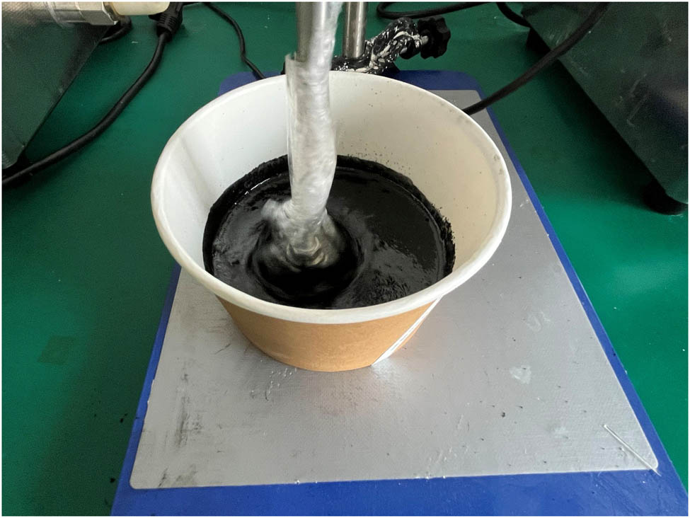
CNTs with different mass fractions (0.5, 1, 1.5, 2, 2.5%) were added to the solution of type 901 vinyl resin and curing agent (Hebei Benfeng Environmental Protection Technology Co., Ltd.), and the mixture ratio of resin and curing agent is 50:1. Table 1 shows the related parameters of the CNT powder. The nano-reinforced resin solution was prepared by mixing the liquid with a high-speed mixer at a speed of 200 rpm, as shown in Figure 1. Nano-reinforced GFP was prepared by the vacuum-assisted molding process. E-5/4 plain GFP (0°/90°) and E-BX GFP (+45°/−45°) (Changzhou Walico New Materials Co., Ltd.) were woven in different layers (4, 8, and 12 layers), and one layer of E-5/4 plain (0°/90°) and one layer of E-BX (+45/−45) were successively crossed and tiled in the mold. As shown in Figure 2(c), by sealing strips, the vacuum bag and the mold cavity are sealed to form a sealing system. As the air in the closed system is pumped out, the system forms a negative pressure generated by the vacuum, which makes the resin pumped into the fiber layer through the laid guide pipes and guide nets to infiltrate the glass fiber layer. The vacuum pressure is 0.08 MPa in the process of resin introduction. The vacuum tube was wound to keep the vacuum state. After the resin was completely soaked in the fabric and after the vacuum pressure was kept for 8 h, the vacuum tube was cured in an oven at 90°C for 2 h and dried to room temperature for demolding treatment to obtain CNTs/GFP. This process is shown in Figure 3.
Related parameters of CNTs
| Materials | Purity | Inner diameter (nm) | Outer diameter (nm) | Length (um) | Specific surface area (m2/g) | Density (g/cm3) | Carboxyl content (mmol/g) | Manufacturer |
|---|---|---|---|---|---|---|---|---|
| Carboxylated multi-wall CNTs | ≥99% | 3–5 | 8–15 | 5–15 | ≥190 | 0.10 | 1 | Shenzhen Sui Heng Technology Co., Ltd. |
Preparation of resin solution reinforced by CNTs.

(a) E-5/4 plain GFP (0°/90°), (b) E-BX GFP (+45°/−45°), and (c) layering method.

Vacuum negative pressure process of CNTs/GFP.
2.2 Determination of the optimum mass fraction of CNTs and resin solution
2.2.1 Scanning electron microscopy (SEM) analysis of CNTs and resin solution
The SEM is a Phenom XLG2 instrument. The system can analyze samples with a maximum of 100 mm × 100 mm. The resolution is better than 8 nm, the vacuum time is less than 20 s, and the acceleration voltage range is 4.8–20.5 kV, which are used to observe the surface of various solid substances. In the experiment, the sample is scanned by a very narrow, focused, high-energy electron beam, and the interaction between the beam and the material can excite a variety of information.
CNTs have excellent physical and chemical properties. When it is compounded with vinyl resin, it can enhance various properties of the resin and obtain high-performance fiber composites with excellent properties. To determine the optimal mass fraction of the CNT powder mixed with the resin, different mass fractions of CNTs were selected to mix evenly with the resin, poured into the mold, solidified, and characterized by SEM (Figure 4). The red dotted line in the figure is marked as the agglomeration phenomenon, and compared with the nonreinforced sample, the best mass fraction is selected by the agglomeration phenomenon of the sample after adding CNTs. When the mass fraction of CNTs is 0.5%, the agglomeration of CNTs occurs in a small range, and when the mass fraction is 1%, the agglomeration area of CNTs is larger, which shows that the dispersion of CNTs in the resin solution is not uniform. When the mass fraction is 1.5%, the agglomeration phenomenon hardly occurs, indicating that the solution at this concentration is mixed most uniformly. The agglomeration of CNTs in the resin solution was also obvious when the mass fraction was 2 and 2.5%; therefore, a 1.5% concentration was chosen to prepare the mixture solution of CNTs and resin [19,20].

SEM images of different mass fractions of CNT end-mixed solution with resin: (a) nonreinforced, (b) 0.5%, (C) 1%, (d) 1.5%, (e) 2%, and (f) 2.5%.
2.2.2 Analysis of mechanical properties of CNTs and resin solution
To better determine the mass ratio of CNTs and resin solution, the best mass fraction of CNTs was selected by combining the mechanical test. The CNTs of different mass fractions were mixed with the solution of the resin evenly and poured into the mold after curing the three-point bending performance test; the test results are shown in Figure 5. A comprehensive comparison of the curves shows that all the samples show a curve of first increasing and then decreasing; the turning change is due to the failure of the samples after reaching the limit value under the action of external forces. The load value of the nonreinforced sample is the smallest, and after reaching the peak, it shows a sharp decline trend, indicating that it has a strong brittleness. After treatment, the samples can bear a larger force and a longer time, indicating that the fracture toughness of the resin is reinforced by CNTs. When the mass fraction is 1.5%, it is found that the sample has the best bending resistance. Therefore, the mixture of CNTs and resin was prepared with a mass fraction of 1.5%.

Test results of bending mechanical properties.
3 Analysis of mechanical properties of CNTs/GFP
3.1 Tensile test
The tensile properties were tested on the universal material strength tester (UTM5105, Shenzhen Sansi Zongheng Science and Technology Co, Ltd.). The dynamic loading speed is 120 mm/min, and the static loading speed is 2 mm/min. According to the standard ASTM D3039, the specimen was cut to 250 mm × 15 mm in the tensile test, and the specimen was clamped vertically to make the upper and lower clamps of the tester even with the edge of the specimen, and the load–displacement curve was observed. The universal material strength testing machine and the drawing of the tensile test are shown in Figures 6 and 7.

UTM5105 universal material strength testing machine.

Tensile test for GFP.
3.1.1 Analysis of static tensile test results
Figure 8 shows the static tensile test results. Whether reinforced by CNTs is represented by “E/N,” then 4N represents four layers of nonreinforced GFP, and so on. From the data in the figure, it can be seen that, at the initial stage, with the increase of the load value, the samples of each layer are subjected to the tensile force, and the composite materials are gradually destroyed. The curve tends to fall back, and the sample has the phenomenon of fracture. Comparing the nonreinforced and reinforced samples, it is found that the reinforced samples have a greater increase in peak load than the nonreinforced samples; moreover, the peak load of the 8- and 12-layer specimens after treatment is much higher than that of the four-layer specimens. The initial state of all curves in the figure increases linearly. With an increase in displacement, the load increases, the work of failure also increases, and the damage is gradually intense. Furthermore, delamination occurred in the middle part of the specimen, and the load dropped instantly when it reached its peak value, indicating that the specimen was completely invalid. After adding CNTs, the loading value at the initial stage increased gradually, and the peak load also increased significantly, indicating that CNTs reinforced the tensile properties of GFP.

Tensile test for GFP: (a) 4-layer, (b) 8-layer, and (a) 12-layer.
3.1.2 Analysis of dynamic tensile test results
Figure 9 shows the results of the dynamic tensile test. As can be seen from the data in the figure, the peak load of GFP samples after adding CNTs increased obviously, and the increasing trend of all curves in the initial stage was the same. With the increase in displacement, the load value increased, and the damage to the specimen also increased. Because of the brittleness of GFP, the fibers in the outer layer of the sample were slightly damaged, and a few fibers were broken and shed on the surface. When the load reaches the limit value, the curve shows a sharp decline, and the specimen breaks from the middle part. Compared with nonreinforced samples, the peak load of all samples increased obviously after adding CNTs, and the peak load of 8- and 12-layer samples was larger than that of 4-layer samples, indicating that CNTs reinforced the mechanical properties of GFP.

Tensile test for GFP: (a) 4-layer, (b) 8-layer, and (a) 12-layer.
3.2 Bending performance test
The standard of bending performance is ASTM D7264, the sample size is 120 mm × 20 mm, and the span ratio is 16:1. The loading speed of the static bending test is 2 mm/min, and that of the dynamic bending test is 120 mm/min. The sample with good quality and standard size was selected to test its bending performance; the sample was laid on the support, the pressure head of the tester and the center of the sample level were made, and then the pressure head was dropped to just contact with the sample and started testing (Figure 10).

Bending performance test.
3.2.1 Analysis of static bending test results
Figure 11 shows the static bending performance test results. As can be seen from the data in the figure, the curve fluctuates under the action of three-point bending; because of the multi-layer structure of CNTs/GFP, the sample has an interlayer fracture, and part of the brittle fracture of GFP appears. With an increase in displacement, the composite is subjected to the action of both pressure and tensile force, the surface of the composite is cracked, the composite gradually occurs bending deformation, and finally leads to the failure of the composite. As can be seen from the figure above, the peak load of the sample with CNTs is obviously higher than that of the nonreinforced sample, and the peak load of the sample with 8-layer is more obvious than that of the sample with 4- and 12-layers; the results show that CNTs improve the bending performance of GFP.

Static bending performance test results: (a) 4-layer, (b) 8-layer, and (a) 12-layer.
3.2.2 Analysis of dynamic bending test results
Figure 12 shows the results of the static bending test. From the data in the diagram, it can be seen that the initial stage of the curve shows linear growth, and the deformation of the sample is obvious. Because of its toughness, GFP can withstand large deformation. The peak load of the reinforced samples was significantly higher than that of the nonreinforced samples, indicating that the mechanical properties of GFP could be improved by adding CNTs. Moreover, the peak load of the four layers is small, which indicates that the bending resistance is weak. When the peak load of 8- and 12-layer samples is larger than that of 4-layer samples, it can be seen that the number of layers is also one of the decisive factors for the mechanical properties of composites. It is found that the 8-layer composite has better mechanical properties by comprehensive bending and tensile tests, so the 8-layer composite is selected for ballistic test and the comparison of energy absorption between nonreinforced and reinforced samples.

Static bending test: (a) 4-layer, (b) 8-layer, and (a) 12-layer.
3.3 Analysis of tensile fracture morphology
The fracture section of the specimen after tensile testing was characterized by SEM. The red dotted line shows the detachment of GFP from the resin. In order to observe the binding of GFP to the resin better, SEM analysis at 1,500, 3,000, and 600 times, respectively, was selected. The binding of GFP to the resin can be clearly seen in Figure 13(a) and (b), as well as in Figure 14(a) and (b): the nonreinforced sample produced more severe damage when it was damaged, with GFP apparently detached from the resin. The space between the fiber bundle is large. The fiber is pulled out from the resin matrix, and the fiber breaks. However, after adding CNTs, the bonding ability of the fiber and resin was improved. Obviously, the gap between the fiber and resin matrix was smaller, and the bonding was tight. Comparing Figures 13(c) and 14(c), it can be seen that the nonreinforced sample has obvious delamination, the surface of the fiber is smooth, and there is no resin coating; however, after adding CNTs, only a small number of the exposed fiber bundles were observed, and a large number of fiber bundles were coated with resin with slight delamination, which indicated that the combination of the fiber and resin was improved by adding CNTs, and the mechanical properties of GFP were reinforced.

SEM fracture morphology of nonreinforced tensile specimens at different magnifications: (a) 1,500 times, (b) 3,000 times, and (a) 600 times.

SEM fracture morphology of nonreinforced tensile specimens at different magnifications: (a) 1,500 times, (b) 3,000 times, and (a) 600 times.
It should be noted that the preparation and mechanical properties of STF/Kevlar composite fabric include the selection of STF and Kevlar materials, the weaving of Kevlar, the preparation of composite materials, and the analysis of performance characterization results. The above research results have been published [13]. The experimental results show that the STF/Kevlar composite fabric has excellent mechanical and protective properties and can be used for bullet body protection.
4 Ballistic impact test of CNTs/GFP-STF/Kevlar fiber-reinforced composite structure
4.1 Bullet and target materials
Different thicknesses of CNTs/GFP are used as upper and lower panels, 3D and 2D, with 12/cm longitude and weft density STF/Kevlar composite fabric as core material, respectively. Then, CNTs/GFP-STF/Kevlar fiber-reinforced composite (CNTs/GFP-STF/Kevlar) was prepared by bonding the panel and the core with a neutral silicone weather-resistant adhesive for 6 h. Figure 15 is a schematic of the structure of CNTs/GFP-STF/Kevlar, and Figure 16 is a physical map of the fiber-reinforced composite structure with different GFP layers and Kevlar structures, with a size of 200 mm × 200 mm; the GFP has n layers and STF/Kevlar is a 2D or 3D structure. For example, 8/3D represents the 8-layer of GFP and the 3D structure of STF/Kevlar. Whether the nano-reinforced can be judged by color because CNTs are black, so the nano-reinforced plate is black, to the letter E, that is, E-8/3D. The nonreinforced is white, represented by the letter N, which is N-8/3D. Figure 17 shows the side profile of the composite panel, showing a clear difference in the thickness and structure between 3D and 2D Kevlar. In the impact test, the plate is cut into 100 mm × 100 mm according to the size of the equipment, as shown in Figure 18. The ballistic impact test was carried out on three kinds of plates with different bullet shapes and parameters: cylindrical, semicircular, and conical. The bullet specifications and physical drawings are shown in Figures 19 and 20, respectively.

Structure schematic of CNTs/GFP-STF/Kevlar.

Composite structure physical diagram: (a) N-4/3D, (b) E-4/2D, (c) E-8/2D, (d) E-12/2D, (e) E-4/3D, (f) E-8/3D, and (g) E-12/3D.

Side profile of the composite plate: (a) E-12/2D and (b) E-4/3D.

Target for the ballistic impact test.

Different bullet specification parameters. (a) Cylindrical, (b) hemispherical, and (c) cone.

Physical drawings of different bullets.
4.2 Experimental loading and testing system
An experimental loading and testing system for fragment penetration into the CNTs/GFP-STF/Kevlar composite structure was constructed. A series of experiments were carried out to investigate the impact velocity of fragments driven by a light gas gun loading system. Figure 21 shows an experimental loading and testing system for fragment penetration into the CNTs/GFP-STF/Kevlar composite.

Experimental loading and testing system for fragment penetration into the CNTs/GFP-STF/Kevlar composite structure.
The impact temperature increase in the missile–target interaction region was measured in real-time by an Infrared Thermal Imager. A plane mirror (calcium fluoride) was placed in front of the target, which was inclined 45° to the ballistic direction. The real-time image of the contact surface of the missile and the target was reflected by the plane mirror into the Infrared Thermal Imager acquisition system. The deformation process of the CNTs/GFP-STF/Kevlar composite structure was captured by Fastcam SA-Z high-speed camera. The type of sensor is CCD, the structure of the sensor is an array camera, and the frame rate is 60,000 frames/s [21]. A number of PVDF piezoelectric sensors were prefabricated on the surface and interface of the panel, and sandwich and back panel to test the impact pressure at the interface. The shock pressure test system consists of the PVDF piezoelectric sensor, external circuit, and oscilloscope. The impulse pressure is collected by the current mode. Figure 22 shows the PVDF current-mode test circuit.

PVDF current mode test circuit.
A PVDF piezoelectric sensor is used as the data acquisition unit of the pressure test system. In the experiment, PVDF and test resistance r are connected in parallel to form a charge release circuit. When PVDF is subjected to shock pressure, the electric charge generated by PVDF is derived through the circuit formed by an external resistor R, and the voltage signal
where K is the dynamic piezoelectric coefficient of the PVDF piezoelectric sensor, R is the sampling resistance, and A is the effective bearing area of PVDF.
The strain gauges were pasted on the surface of the composite structure, and the signals sensed by the strain gauges were collected by the super-dynamic strain gauges. According to the relation between the instantaneous displacement of the impact point and the external load, the energy absorption response characteristics of each target layer are obtained. The cumulative energy absorption can be obtained by the approximate integral method.
The energy absorbed by the target is KE:
where M is the fragment mass, V S is the target velocity, and V R is the residual velocity.
5 Analysis of impact test results
5.1 Experimental phenomena
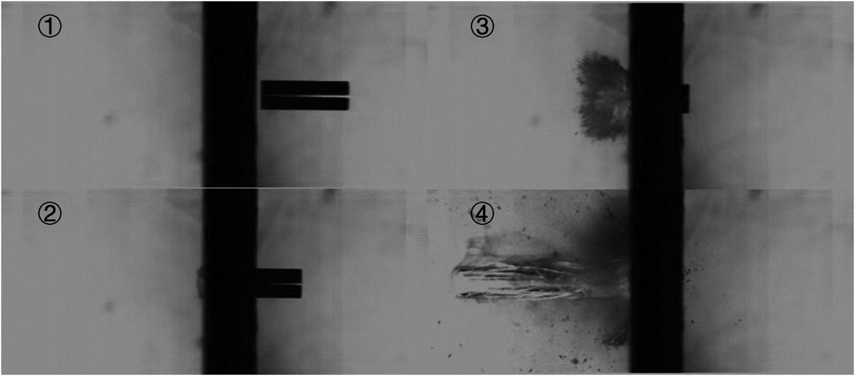
The ballistic impact tests of three kinds of bullets with different parameters on CNTs/GFP-STF/Kevlar fiber-reinforced composite structures were carried out; the test neutron velocity is greater than 180 m/s, and all targets are penetrated. Figures 23 and 24 show the high-speed photographic penetration of a cylindrical bullet through the E-4/2d and N-4/2D composite structures, respectively, with the bullet moving from right to left. This shows the physical phenomenon of the experimental process. As can be seen from the image, the bullet penetrated the GFP panel and immediately touched the GFP back panel; however, by this time, the bullet body had been wrapped in STF/Kevlar fibers. Radial GFP and STF/Kevlar fragments were generated in the dorsal direction when the bullet penetrated the target plate by half the volume. However, in the panel direction, there were fewer fragments, which indicated that CNTs/GFP and STF/Kevlar fibers covered the fragments obviously. In addition, STF/Kevlar fibers exert a large strain on the projectile after the projectile penetrates the target completely. The STF/3DKevlar fiber in Figure 24 produces a more pronounced shear thickening, with much less fracture than the STF/2DKevlar fiber in Figure 23, and a greater effect on the kinetic energy consumption of the bullet.

Cylindrical bullet impact diagram of the E-4/2D composite structure.

Cylindrical bullet impact diagram of the E-4/3D composite structure.
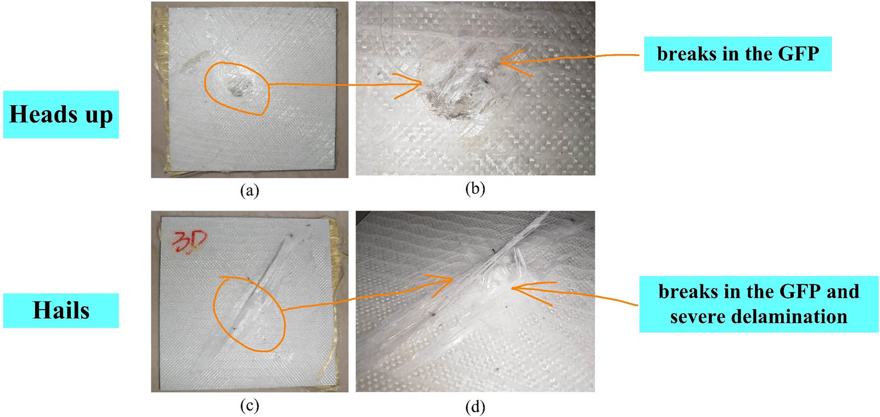
Also using the cylindrical bullet as an example, Figures 25 and 26 show the failure pattern of the target plate after testing. As can be seen from the figure, the target plate is a regular cylindrical head-on surface, which is only a small part of the fiber fracture phenomenon. At the back of the bullet, the CNTs/GFP perforations were irregular and round, with the stratification failure of GFP. Compared with the nonreinforced 8/3D composite structure, the reinforced 8/3D composite structure had a milder delamination failure of GFP due to the addition of CNTs or even no delamination. The above phenomena indicate that the combination of GFP with matrix and dispersion media is reinforced by adding CNTs, and the fracture toughness of GFP is effectively reinforced. STF/Kevlar fibers exhibit typical tensile fracture failure, which dissipates the residual kinetic energy of the bullet after it penetrates the target plate.

Failure morphology of the N-8/3D composite structure: (a) heads up and (b) hails.

Failure morphology of the N-8/3D composite structure.
5.2 Energy absorption analysis
5.2.1 Numerical analysis
Table 2 shows the test results of ballistic impact performance with different parameters. According to the data in the table, the energy absorption growth rate can be calculated by combining formula (3). Taking the 8-layer of GFP as an example, the shock absorptivity is shown in Figure 27. Comparing the energy absorption values of the 8-layer composite structure, it can be seen that the 8-layer CNTs/GFP-STF/Kevlar composite structure is more than 20% higher than that of the pure 8-layer GFP-Kevlar composite structure in the penetration experiments of three kinds of bullets; the lowest can be increased by 21.92% and the highest by 48.23%. The results show that the addition of CNTs, STF, and Kevlar with 3D weave structures plays an active role in improving the impact resistance of composite structures.
Impact test result parameters
| Sample parameters | Warhead shape | Initial velocity (m/s) | Residual velocity (m/s) | Energy absorption (kJ) |
|---|---|---|---|---|
| −8/2D | Hemispherical | 186.766 | 161.466 | 151.98 |
| −8/2D | Cylindrical | 183.086 | 154.967 | 163.97 |
| −8/2D | Cone | 187.727 | 174.832 | 80.65 |
| −8/3D | Hemispherical | 185.390 | 155.887 | 173.68 |
| −8/3D | Cylindrical | 183.446 | 149.397 | 195.49 |
| −8/3D | Cone | 186.716 | 162.966 | 143.2 |
| 4/2D | Hemispherical | 187.347 | 168.347 | 116.58 |
| 4/2D | Cylindrical | 182.244 | 157.087 | 147.26 |
| 4/2D | Cone | 187.025 | 177.202 | 61.72 |
| 4/3D | Hemispherical | 186.148 | 160.945 | 150.90 |
| 4/3D | Cylindrical | 183.403 | 145.545 | 214.82 |
| 4/3D | Cone | 187.322 | 173.153 | 88.11 |
| 8/2D | Hemispherical | 186.836 | 155.062 | 187.39 |
| 8/2D | Cylindrical | 181.283 | 144.87 | 204.86 |
| 8/2D | Cone | 188.165 | 168.749 | 119.54 |
| 8/3D | Hemispherical | 187.918 | 151.535 | 213.04 |
| 8/3D | Cylindrical | 185.947 | 144.079 | 238.35 |
| 8/3D | Cone | 187.832 | 155.693 | 190.45 |
| 12/2D | Hemispherical | 187.873 | 145.327 | 244.54 |
| 12/2D | Cylindrical | 183.464 | 129.568 | 291.03 |
| 12/2D | Cone | 187.007 | 160.460 | 159.12 |
| 12/3D | Hemispherical | 187.052 | 155.327 | 192.68 |
| 12/3D | Cylindrical | 184.583 | 129.743 | 297.35 |
| 12/3D | Cone | 186.417 | 157.650 | 170.74 |

Impact test energy absorption contrast.
5.2.2 Morphology analysis
According to the physical phenomenon and shape of the target during and after the bullet penetration, the damage to each layer in the composite structure is characterized by industrial micro-CT. The micro-damage degree of the material was reconstructed by the CT scan, and the damage mode was extracted based on the visualized images obtained by the CT scan. The energy absorption principle of the CNTs/GFP-STF/3DKevlar fiber-reinforced composite structure was analyzed and explained.
5.2.2.1 CNTs/GFP-STF/3DKevlar versus GFP-3DKEVLAR
In the case of 8-layer GFP, the penetration process of three different projectiles is shown in Figures 28–33. From Section 5.2.1, it can be seen that the energy absorption growth rate of the reinforced composite structure is increased by more than 20%, and the highest is 48.23%. In Figures 23 and 24, when the cylindrical bullet first penetrated the back plate, the back plate of the reinforced composite structure was diffused like a magnet, while the back plate of the nonreinforced composite structure was broken like glass, which indicates that the overall structural strength of CNTs/GFP is higher. As shown in Figures 28–33, the most obvious similarity is that Kevlar in the unreinforced composite structure has reached a fracture state when the bullet travels uniformly after it has completely penetrated the target plate, the Kevlar in the reinforced composite structure is still in a tensile state and acts as a kinetic energy drain on the bullets (cylindrical and hemispherical). Alternatively, when both Kevlar are in a fracture state, the elongation of the Kevlar in the reinforced composite is higher (tapered bullet) [22]. The results show that the STF/3DKevlar is thickened by the pressure at a high strain rate, and the residual kinetic energy of the bullet is consumed more effectively.

Cylindrical bullet impact diagram of the E-8/3D composite structure.
Cylindrical bullet impact diagram of the N-8/3D composite structure.

Hemispherical bullet impact diagram of the E-8/3D composite structure.

Hemispherical bullet impact diagram of the N-8/3D composite structure.

Conic bullet impact diagram of the E-8/3D composite structure.

Conic bullet impact diagram of the N-8/3D composite structure.
In addition, Figures 34 and 35, respectively, show the failure morphology of the E-8/3D and N-8/3D composite structures under penetration of conical bullets. From the point of view of the head-on surface, the irregular circular holes and the shear fracture of GFP fibers appeared in both targets. It was evident that GFP reinforced by CNTs had a shorter length of broken fibers and better fiber-to-resin binding, with little delamination failure. On the back side, the GFP reinforced by CNTs showed only a slight delamination failure. On the contrary, the shear fracture and delamination failure of GFP were very obvious in the unreinforced target. From the above analysis, it can be concluded that CNTs/GFP-STF/3DKevlar fiber reinforced composite structure has a better effect on the kinetic energy consumption of bullets.

Failure morphology of the E-8/3D composite structure.
Failure morphology of the N-8/3D composite structure.
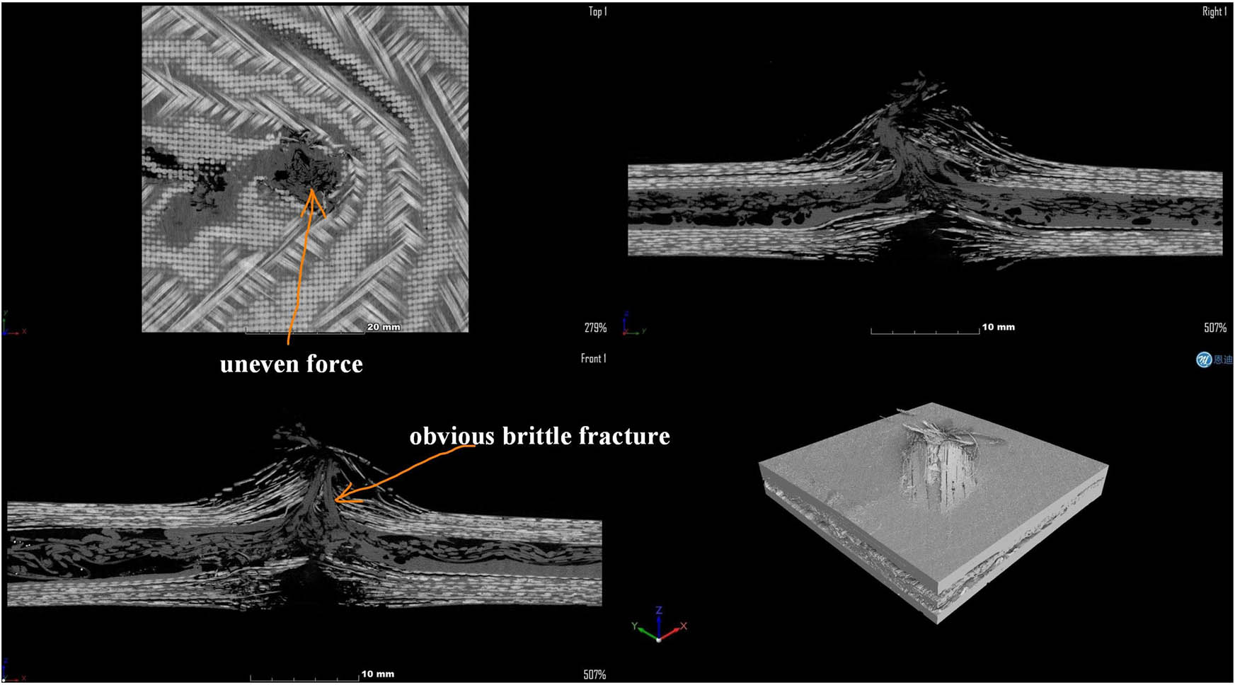
Furthermore, Figures 36–38 show a CT scan of the E-8/3D composite, and Figures 39–41 show a CT scan of the N-8/3D composite. The industrial micro-CT (Diondo d 2, Germany) was tested with a high-resolution 300 kV micro-focus industrial CT detection system. The scanning mode was standard cone-beam CT scanning; the distance from the ray source to the detector (FDD) was 800 mm, and the distance from the ray source to the sample (FOD) was 160 mm. The X-ray voltage is 110 kV, the tube current is 100 μA and the integral time is 2,000 ms [23]. The number of samples is 1,795, the reconstruction matrix is 4,000 × 4,000, and the voxel size is 0.02 mm. The high-resolution CT detection system can be tested in the form of two-dimensional sectional images or three-dimensional images without damaging the detected object and clearly, accurately, and intuitively display the internal structure, composition, material, and defects of the object to be tested [24].

Four-view CT for the E-8/3D composite structure.

Cross-sectional view of the CT for the E-8/3D composite structure.

Four views of gap analysis for the E-8/3D composite structure.
Four-view CT for the N-8/3D composite structure.

Cross-sectional view of the CT for the N-8/3D composite structure.
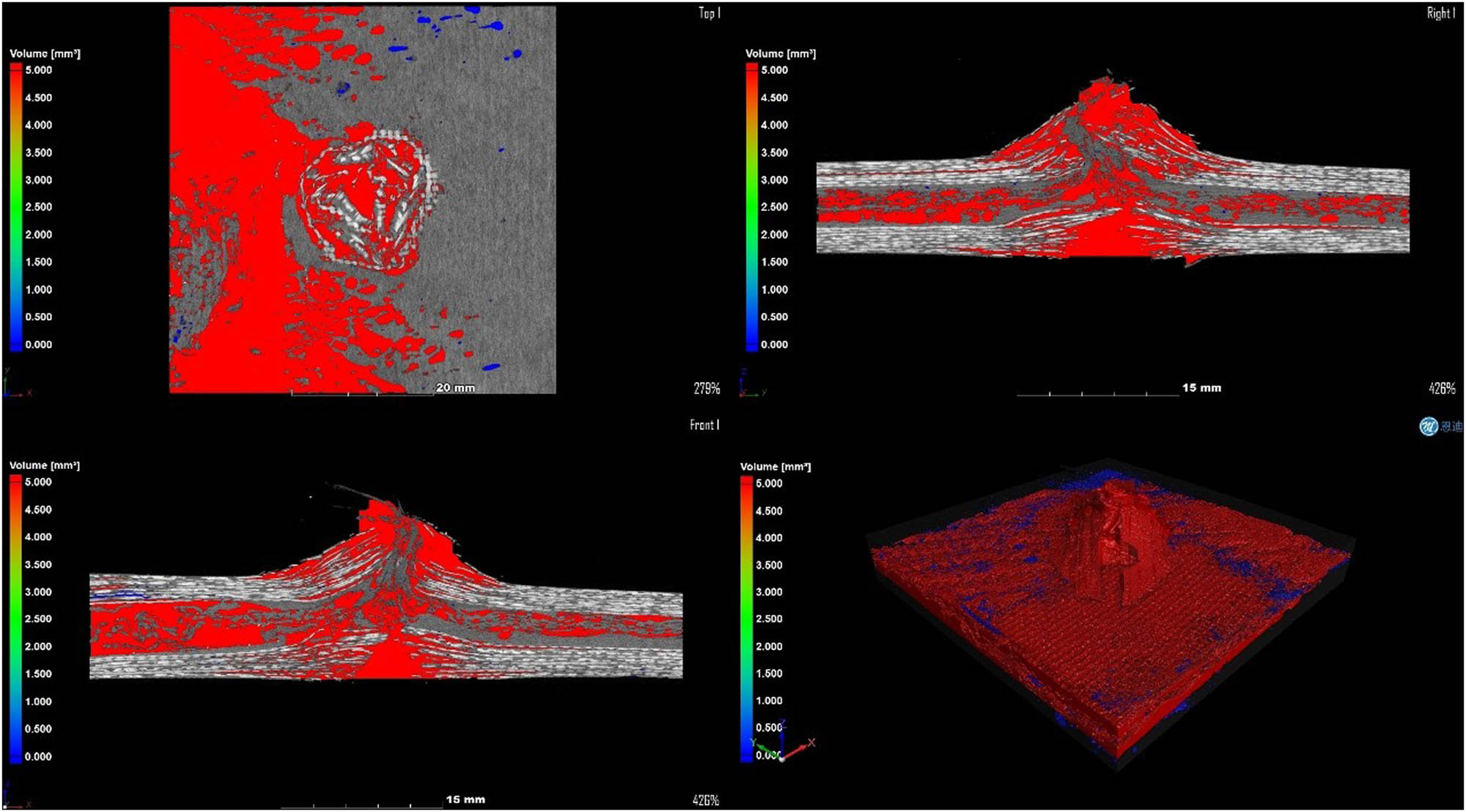
Four views of gap analysis for the N-8/3D composite structure.
In addition to the phenomena shown in Figures 34 and 35, in the CT figure, it can be observed that the perforations on the head-on and back-on the reinforced target plate are more regular, and the cracks are smaller. The unreinforced target GFP was more brittle and had a higher degree of shear fracture. The results indicated that CNTs reinforced the adhesion of GFP to the resin, and the stress distribution on the GFP surface was more uniform. The tensile ratio of Kevlar is higher in the reinforced target plate [25]. The results show that the mechanical properties of the reinforced target plate are better, and the kinetic energy consumption of the bullet is stronger.
Table 3 shows the results of the CT examination. According to the data in the table, the pore volume of the E-8/3D composite structure is 2% higher than that of the N-8/3D composite structure, and the pore proportion of the E-8/3D composite structure is 1% higher than that of the N-8/3D composite structure, which shows that CNTs and STF play an active role in improving the impact resistance of the composite structure.
CT examination results data
| Sample parameters | Pore volume (mm3) | Material volume (mm3) | Total volume (mm3) | Pore percentage (%) |
|---|---|---|---|---|
| E-8/3D | 5146.309 | 21390.334 | 26536.643 | 19.393218 |
| N-8/3D | 5237.421 | 21532.627 | 26770.048 | 19.564481 |
5.2.2.2 STF/3DKevlar versus STF/2DKevlar
Figures 42 and 43 show the impact of a cylindrical bullet penetrating a target plate with STF/2DKevlar and STF/3DKevlar as the core materials, respectively. It can be seen that STF/3DKevlar has a larger covering area and a higher tensile ratio after the bullet completely penetrates the target plate. In contrast, STF/2DKevlar is slightly deficient in fiber density and strength, indicating that 3D braided Kevlar has a better kinetic energy consumption for bullets.

Cylindrical bullet impact diagram of the E-8/3D composite structure.

Cylindrical bullet impact diagram of the E-8/2D composite structure.
6 Conclusion
A fiber-reinforced composite structure with CNTs/GFP clip STF/3DKevlar was designed and prepared, and by the mechanical property test, ballistic impact test, combined with experimental phenomena and industrial CT detection results, the mechanical behavior of the composite structure is studied, and the failure mode of the composite structure and its energy dissipation and protection behavior under impact are analyzed. The main conclusions are as follows:
The single-layer and multi-layer glass fiber cloth were braided, and the optimum mass fraction of the CNT powder mixed with resin was determined by SEM. The mechanical property test showed that the increase of GFP layer number and the addition of CNTs could improve the adhesion of GFP to the matrix and optimize the fracture toughness and mechanical properties.
The shear thickening effect of STF will reduce the yarn displacement when it is impacted by the projectile and increase the friction between the matrix, the yarn, and the projectile. The combination of STF and Kevlar can effectively improve the overall tensile properties of Kevlar.
The energy absorption of the CNTs/GFP-STF/Kevlar fiber-reinforced composite structure was increased by 21.92 and 48.23% compared with that of unreinforced GFP/Kevlar under the impact of bullets with three different parameters. The damage morphology of CNTs/GFP-STF/Kevlar fiber-reinforced composite is more regular, which proves that the stress distribution is more uniform and the overall structure strength is better.
To sum up, both fabric structure and nanoparticle concentration play an active role in the mechanical and protective properties of the composite structures. The experimental results can provide technical support for the development of high-performance protective structures in the fields of weapon and soldier equipment.
-
Funding information: This research was conducted by the equipment synthesis research project: Study on the coupling effect between penetration and shock wave of the composite structure of STF Kevlar fabric impregnated with nano-reinforced GFP (No. 5362486924).
-
Author contributions: Yangshuo Liu – thought arrangement, experimental scheme, and thesis writing, Xingyong Gao – project management and paper revision, Ping Cui – paper revision, Mingjiang Han – experimental testing, Ruosi Yan – paper revision, Huanan Wei – project management, Hang Zhou – experimental testing, and Hao Luo – experimental testing. All authors have accepted responsibility for the entire content of this manuscript and approved its submission.
-
Conflict of interest: The authors state no conflict of interest.
-
Data availability statement: The datasets generated and/or analyzed during the current study are available from the corresponding author on reasonable request.
References
[1] Weng DW. Research status and development trend of protective materials for tank and armored vehicles. Metall Mater. 2019;39(4):63–4.Search in Google Scholar
[2] Qiu J, Wang YG. New development of armor protection technology. J Armament Eng. 2016;37(3):15–9.Search in Google Scholar
[3] Cao LY, Luo XB, Liu GQ, Gao XY. Development and application of military armor protection technology. Packag Eng. 2018;39(3):223–8.Search in Google Scholar
[4] Jiang T, Huang YD. Preparation technology, research and development status, development trend and application status of intermetallics/ceramic composites. Ceramics. 2023;12:9–13.Search in Google Scholar
[5] Zhou SH. Study on high entropy refractory metal carbide reinforced titanium nitride based cermets[D]. Master's Thesis, Hunan University of Technology; 2023.Search in Google Scholar
[6] Song YQ, Xu R, Fan CY. Multi-layer composite protective structure of fuze booster grain under fragment impact environment. J Detect Control. 2024;46(4):134–8 + 156.Search in Google Scholar
[7] Doolan JA, Alesbrook LS, Baker K, Brown IR, Williams GT, Hilton K, et al. Next-generation protein-based materials capture and preserve projectiles from supersonic impacts. Nat Nanotechnol. 2023;18:1060–6.10.1038/s41565-023-01431-1Search in Google Scholar PubMed PubMed Central
[8] Chen J, Kang T, Cui Y, Xue J, Xu H, Nan J. Nonflammable and thermally stable glass fiber/polyacrylate (GFP) separator for lithium-ion batteries with enhanced safety and lifespan. J Power Sources. 2021;496:229862.10.1016/j.jpowsour.2021.229862Search in Google Scholar
[9] Pan GC, Su H, Li XX, Wang JS. Coupled FEM-SPH simulation of the protective properties for metal/ceramic composite armor. Int J Lightweight Mater Manuf. 2023;6(4):543–51.10.1016/j.ijlmm.2023.05.007Search in Google Scholar
[10] Hong X, Ma Y, Lei Z, Bai R, You M, Bai H, et al. Mesoscopic finite-element prediction method for impact-energy absorption mechanism of multiphase STF/Kevlar composite fabric. Compos Struct. 2024;118554.10.1016/j.compstruct.2024.118554Search in Google Scholar
[11] Tang E, Tan H, Wang R, Chen C, Han Y, Chang M, et al. Mechanical behavior of STF impregnation and anti-impact performances of Kevlar and UHMPWEF fabric impregnations. Compos Struct. 2024;341:118228.10.1016/j.compstruct.2024.118228Search in Google Scholar
[12] Biradar A, Arulvel S, Kandasamy J. A hybrid approach of NiP coating and STF impregnation of UHMWPE fabric for conductive soft body armor. J Mater Res Technol. 2024;30:3367–82.10.1016/j.jmrt.2024.04.120Search in Google Scholar
[13] Liu Y, Gao X, Han M, Wei H, Luo H. Research Article Study on dynamic and static tensile and puncture-resistant mechanical properties of impregnated STF multi-dimensional structure Kevlar fiber reinforced composites. Open Phys. 2024;22:20240065.10.1515/phys-2024-0065Search in Google Scholar
[14] Zhang XT. Failure mechanism of STF fiber reinforced composites under ballistic impact[D]. Master's Thesis, Hebei University of Science and Technology; 2023.Search in Google Scholar
[15] Song CM, Zhang ZW, Lin Y, Wang G, Jiang HB. Study on dynamic mechanical properties of ZTA ceramics and anti-penetration behavior of its fiber reinforced composite structure. Prot Work. 2024;46(2):1–8.Search in Google Scholar
[16] Shi YJ. Design and research on composite bullet-proof structure of lightweight ceramic fiber[D]. Master's Thesis, Nanjing University of Science and Technology; 2020.Search in Google Scholar
[17] Liu LL, Xie ZH, Zhao ZH, Liu HM. Progress in dynamic mechanical behavior and numerical study of shear thickening fluids and their composites. Vib Shock. 2023;42(20):58–68.Search in Google Scholar
[18] Zhou YS, Liang S, Wang DP, Dong HY. Study on the anti-penetration performance of hybrid laminated composite armor. New Chem Mater. 2022;50(10):101–10.Search in Google Scholar
[19] Tseng ML, Aslam MI, Ismail EAA, Awwad FA, Gorji NE. CT scan, EBSD and nanoindentation analysis of 3D-printed parts with post-process heat-treatment. Metall Res Technol. 2024;121:101.10.1051/metal/2023083Search in Google Scholar
[20] Liu B, Liu Q, Pan Y, Zhou J, Zhang J, Liu S, et al. An impact-resistant and flame-retardant CNTs/STF/Kevlar composite with conductive property for safe wearable design. Compos Part A: Appl Sci Manuf. 2023;168:107489.10.1016/j.compositesa.2023.107489Search in Google Scholar
[21] Tsirogiannis EC, Daskalakis E, Hassan MH, Omar AM, Bartolo P. Ballistic design and testing of a composite armour reinforced by CNTs suitable for armoured vehicles. Def Technol. 2024;32:173–95.10.1016/j.dt.2023.04.013Search in Google Scholar
[22] Selim MS, El-Safty SA, Shenashen MA, Elmarakbi A. Advances in polymer/inorganic nanocomposite fabrics for lightweight and high-strength armor and ballistic-proof materials. Chem Eng J. 2024;493:152422.10.1016/j.cej.2024.152422Search in Google Scholar
[23] Dasgupta K. Role of carbon nanotubes in the ballistic properties of boron carbide/carbon nanotube/ultrahigh molecular weight polyethylene composite armor. Ceram Int. 2020;46(4):4137–41.10.1016/j.ceramint.2019.10.129Search in Google Scholar
[24] Zhou H, Li SJ, Ma HJ. Perforation performance and mechanism of a torch utilizing Al/PTFE/Fe2O3/CuO thermite composites. Therm Sci Eng Prog. 2024;51:102612.10.1016/j.tsep.2024.102612Search in Google Scholar
[25] Andreotti R, Quercia M, Casaroli A, Boniardi MV. Load history estimation for ballistic impacts with bullet-splash, Procedia Structural Integrity. Procedia Struct Integr. 2023;51:37–43.10.1016/j.prostr.2023.10.064Search in Google Scholar
© 2025 the author(s), published by De Gruyter
This work is licensed under the Creative Commons Attribution 4.0 International License.
Articles in the same Issue
- Research Articles
- Single-step fabrication of Ag2S/poly-2-mercaptoaniline nanoribbon photocathodes for green hydrogen generation from artificial and natural red-sea water
- Abundant new interaction solutions and nonlinear dynamics for the (3+1)-dimensional Hirota–Satsuma–Ito-like equation
- A novel gold and SiO2 material based planar 5-element high HPBW end-fire antenna array for 300 GHz applications
- Explicit exact solutions and bifurcation analysis for the mZK equation with truncated M-fractional derivatives utilizing two reliable methods
- Optical and laser damage resistance: Role of periodic cylindrical surfaces
- Numerical study of flow and heat transfer in the air-side metal foam partially filled channels of panel-type radiator under forced convection
- Water-based hybrid nanofluid flow containing CNT nanoparticles over an extending surface with velocity slips, thermal convective, and zero-mass flux conditions
- Dynamical wave structures for some diffusion--reaction equations with quadratic and quartic nonlinearities
- Solving an isotropic grey matter tumour model via a heat transfer equation
- Study on the penetration protection of a fiber-reinforced composite structure with CNTs/GFP clip STF/3DKevlar
- Influence of Hall current and acoustic pressure on nanostructured DPL thermoelastic plates under ramp heating in a double-temperature model
- Applications of the Belousov–Zhabotinsky reaction–diffusion system: Analytical and numerical approaches
- AC electroosmotic flow of Maxwell fluid in a pH-regulated parallel-plate silica nanochannel
- Interpreting optical effects with relativistic transformations adopting one-way synchronization to conserve simultaneity and space–time continuity
- Modeling and analysis of quantum communication channel in airborne platforms with boundary layer effects
- Theoretical and numerical investigation of a memristor system with a piecewise memductance under fractal–fractional derivatives
- Tuning the structure and electro-optical properties of α-Cr2O3 films by heat treatment/La doping for optoelectronic applications
- High-speed multi-spectral explosion temperature measurement using golden-section accelerated Pearson correlation algorithm
- Dynamic behavior and modulation instability of the generalized coupled fractional nonlinear Helmholtz equation with cubic–quintic term
- Study on the duration of laser-induced air plasma flash near thin film surface
- Exploring the dynamics of fractional-order nonlinear dispersive wave system through homotopy technique
- The mechanism of carbon monoxide fluorescence inside a femtosecond laser-induced plasma
- Numerical solution of a nonconstant coefficient advection diffusion equation in an irregular domain and analyses of numerical dispersion and dissipation
- Numerical examination of the chemically reactive MHD flow of hybrid nanofluids over a two-dimensional stretching surface with the Cattaneo–Christov model and slip conditions
- Impacts of sinusoidal heat flux and embraced heated rectangular cavity on natural convection within a square enclosure partially filled with porous medium and Casson-hybrid nanofluid
- Stability analysis of unsteady ternary nanofluid flow past a stretching/shrinking wedge
- Solitonic wave solutions of a Hamiltonian nonlinear atom chain model through the Hirota bilinear transformation method
- Bilinear form and soltion solutions for (3+1)-dimensional negative-order KdV-CBS equation
- Solitary chirp pulses and soliton control for variable coefficients cubic–quintic nonlinear Schrödinger equation in nonuniform management system
- Influence of decaying heat source and temperature-dependent thermal conductivity on photo-hydro-elasto semiconductor media
- Dissipative disorder optimization in the radiative thin film flow of partially ionized non-Newtonian hybrid nanofluid with second-order slip condition
- Bifurcation, chaotic behavior, and traveling wave solutions for the fractional (4+1)-dimensional Davey–Stewartson–Kadomtsev–Petviashvili model
- New investigation on soliton solutions of two nonlinear PDEs in mathematical physics with a dynamical property: Bifurcation analysis
- Mathematical analysis of nanoparticle type and volume fraction on heat transfer efficiency of nanofluids
- Creation of single-wing Lorenz-like attractors via a ten-ninths-degree term
- Optical soliton solutions, bifurcation analysis, chaotic behaviors of nonlinear Schrödinger equation and modulation instability in optical fiber
- Chaotic dynamics and some solutions for the (n + 1)-dimensional modified Zakharov–Kuznetsov equation in plasma physics
- Fractal formation and chaotic soliton phenomena in nonlinear conformable Heisenberg ferromagnetic spin chain equation
- Single-step fabrication of Mn(iv) oxide-Mn(ii) sulfide/poly-2-mercaptoaniline porous network nanocomposite for pseudo-supercapacitors and charge storage
- Novel constructed dynamical analytical solutions and conserved quantities of the new (2+1)-dimensional KdV model describing acoustic wave propagation
- Tavis–Cummings model in the presence of a deformed field and time-dependent coupling
- Spinning dynamics of stress-dependent viscosity of generalized Cross-nonlinear materials affected by gravitationally swirling disk
- Design and prediction of high optical density photovoltaic polymers using machine learning-DFT studies
- Robust control and preservation of quantum steering, nonlocality, and coherence in open atomic systems
- Coating thickness and process efficiency of reverse roll coating using a magnetized hybrid nanomaterial flow
- Dynamic analysis, circuit realization, and its synchronization of a new chaotic hyperjerk system
- Decoherence of steerability and coherence dynamics induced by nonlinear qubit–cavity interactions
- Finite element analysis of turbulent thermal enhancement in grooved channels with flat- and plus-shaped fins
- Modulational instability and associated ion-acoustic modulated envelope solitons in a quantum plasma having ion beams
- Statistical inference of constant-stress partially accelerated life tests under type II generalized hybrid censored data from Burr III distribution
- On solutions of the Dirac equation for 1D hydrogenic atoms or ions
- Entropy optimization for chemically reactive magnetized unsteady thin film hybrid nanofluid flow on inclined surface subject to nonlinear mixed convection and variable temperature
- Stability analysis, circuit simulation, and color image encryption of a novel four-dimensional hyperchaotic model with hidden and self-excited attractors
- A high-accuracy exponential time integration scheme for the Darcy–Forchheimer Williamson fluid flow with temperature-dependent conductivity
- Novel analysis of fractional regularized long-wave equation in plasma dynamics
- Development of a photoelectrode based on a bismuth(iii) oxyiodide/intercalated iodide-poly(1H-pyrrole) rough spherical nanocomposite for green hydrogen generation
- Investigation of solar radiation effects on the energy performance of the (Al2O3–CuO–Cu)/H2O ternary nanofluidic system through a convectively heated cylinder
- Quantum resources for a system of two atoms interacting with a deformed field in the presence of intensity-dependent coupling
- Studying bifurcations and chaotic dynamics in the generalized hyperelastic-rod wave equation through Hamiltonian mechanics
- A new numerical technique for the solution of time-fractional nonlinear Klein–Gordon equation involving Atangana–Baleanu derivative using cubic B-spline functions
- Interaction solutions of high-order breathers and lumps for a (3+1)-dimensional conformable fractional potential-YTSF-like model
- Hydraulic fracturing radioactive source tracing technology based on hydraulic fracturing tracing mechanics model
- Numerical solution and stability analysis of non-Newtonian hybrid nanofluid flow subject to exponential heat source/sink over a Riga sheet
- Numerical investigation of mixed convection and viscous dissipation in couple stress nanofluid flow: A merged Adomian decomposition method and Mohand transform
- Effectual quintic B-spline functions for solving the time fractional coupled Boussinesq–Burgers equation arising in shallow water waves
- Analysis of MHD hybrid nanofluid flow over cone and wedge with exponential and thermal heat source and activation energy
- Solitons and travelling waves structure for M-fractional Kairat-II equation using three explicit methods
- Impact of nanoparticle shapes on the heat transfer properties of Cu and CuO nanofluids flowing over a stretching surface with slip effects: A computational study
- Computational simulation of heat transfer and nanofluid flow for two-sided lid-driven square cavity under the influence of magnetic field
- Irreversibility analysis of a bioconvective two-phase nanofluid in a Maxwell (non-Newtonian) flow induced by a rotating disk with thermal radiation
- Hydrodynamic and sensitivity analysis of a polymeric calendering process for non-Newtonian fluids with temperature-dependent viscosity
- Exploring the peakon solitons molecules and solitary wave structure to the nonlinear damped Kortewege–de Vries equation through efficient technique
- Modeling and heat transfer analysis of magnetized hybrid micropolar blood-based nanofluid flow in Darcy–Forchheimer porous stenosis narrow arteries
- Activation energy and cross-diffusion effects on 3D rotating nanofluid flow in a Darcy–Forchheimer porous medium with radiation and convective heating
- Insights into chemical reactions occurring in generalized nanomaterials due to spinning surface with melting constraints
- Influence of a magnetic field on double-porosity photo-thermoelastic materials under Lord–Shulman theory
- Soliton-like solutions for a nonlinear doubly dispersive equation in an elastic Murnaghan's rod via Hirota's bilinear method
- Analytical and numerical investigation of exact wave patterns and chaotic dynamics in the extended improved Boussinesq equation
- Nonclassical correlation dynamics of Heisenberg XYZ states with (x, y)-spin--orbit interaction, x-magnetic field, and intrinsic decoherence effects
- Exact traveling wave and soliton solutions for chemotaxis model and (3+1)-dimensional Boiti–Leon–Manna–Pempinelli equation
- Unveiling the transformative role of samarium in ZnO: Exploring structural and optical modifications for advanced functional applications
- On the derivation of solitary wave solutions for the time-fractional Rosenau equation through two analytical techniques
- Analyzing the role of length and radius of MWCNTs in a nanofluid flow influenced by variable thermal conductivity and viscosity considering Marangoni convection
- Advanced mathematical analysis of heat and mass transfer in oscillatory micropolar bio-nanofluid flows via peristaltic waves and electroosmotic effects
- Exact bound state solutions of the radial Schrödinger equation for the Coulomb potential by conformable Nikiforov–Uvarov approach
- Some anisotropic and perfect fluid plane symmetric solutions of Einstein's field equations using killing symmetries
- Nonlinear dynamics of the dissipative ion-acoustic solitary waves in anisotropic rotating magnetoplasmas
- Curves in multiplicative equiaffine plane
- Exact solution of the three-dimensional (3D) Z2 lattice gauge theory
- Propagation properties of Airyprime pulses in relaxing nonlinear media
- Symbolic computation: Analytical solutions and dynamics of a shallow water wave equation in coastal engineering
- Wave propagation in nonlocal piezo-photo-hygrothermoelastic semiconductors subjected to heat and moisture flux
- Comparative reaction dynamics in rotating nanofluid systems: Quartic and cubic kinetics under MHD influence
- Laplace transform technique and probabilistic analysis-based hypothesis testing in medical and engineering applications
- Physical properties of ternary chloro-perovskites KTCl3 (T = Ge, Al) for optoelectronic applications
- Gravitational length stretching: Curvature-induced modulation of quantum probability densities
- The search for the cosmological cold dark matter axion – A new refined narrow mass window and detection scheme
- A comparative study of quantum resources in bipartite Lipkin–Meshkov–Glick model under DM interaction and Zeeman splitting
- PbO-doped K2O–BaO–Al2O3–B2O3–TeO2-glasses: Mechanical and shielding efficacy
- Nanospherical arsenic(iii) oxoiodide/iodide-intercalated poly(N-methylpyrrole) composite synthesis for broad-spectrum optical detection
- Sine power Burr X distribution with estimation and applications in physics and other fields
- Numerical modeling of enhanced reactive oxygen plasma in pulsed laser deposition of metal oxide thin films
- Dynamical analyses and dispersive soliton solutions to the nonlinear fractional model in stratified fluids
- Computation of exact analytical soliton solutions and their dynamics in advanced optical system
- An innovative approximation concerning the diffusion and electrical conductivity tensor at critical altitudes within the F-region of ionospheric plasma at low latitudes
- An analytical investigation to the (3+1)-dimensional Yu–Toda–Sassa–Fukuyama equation with dynamical analysis: Bifurcation
- Swirling-annular-flow-induced instability of a micro shell considering Knudsen number and viscosity effects
- Numerical analysis of non-similar convection flows of a two-phase nanofluid past a semi-infinite vertical plate with thermal radiation
- MgO NPs reinforced PCL/PVC nanocomposite films with enhanced UV shielding and thermal stability for packaging applications
- Optimal conditions for indoor air purification using non-thermal Corona discharge electrostatic precipitator
- Investigation of thermal conductivity and Raman spectra for HfAlB, TaAlB, and WAlB based on first-principles calculations
- Tunable double plasmon-induced transparency based on monolayer patterned graphene metamaterial
- DSC: depth data quality optimization framework for RGBD camouflaged object detection
- A new family of Poisson-exponential distributions with applications to cancer data and glass fiber reliability
- Numerical investigation of couple stress under slip conditions via modified Adomian decomposition method
- Monitoring plateau lake area changes in Yunnan province, southwestern China using medium-resolution remote sensing imagery: applicability of water indices and environmental dependencies
- Heterodyne interferometric fiber-optic gyroscope
- Exact solutions of Einstein’s field equations via homothetic symmetries of non-static plane symmetric spacetime
- A widespread study of discrete entropic model and its distribution along with fluctuations of energy
- Empirical model integration for accurate charge carrier mobility simulation in silicon MOSFETs
- The influence of scattering correction effect based on optical path distribution on CO2 retrieval
- Anisotropic dissociation and spectral response of 1-Bromo-4-chlorobenzene under static directional electric fields
- Role of tungsten oxide (WO3) on thermal and optical properties of smart polymer composites
- Analysis of iterative deblurring: no explicit noise
- The influence of anisotropy of InP on its elasticity and phonon properties
- Review Article
- Examination of the gamma radiation shielding properties of different clay and sand materials in the Adrar region
- Erratum
- Erratum to “On Soliton structures in optical fiber communications with Kundu–Mukherjee–Naskar model (Open Physics 2021;19:679–682)”
- Special Issue on Fundamental Physics from Atoms to Cosmos - Part II
- Possible explanation for the neutron lifetime puzzle
- Special Issue on Nanomaterial utilization and structural optimization - Part III
- Numerical investigation on fluid-thermal-electric performance of a thermoelectric-integrated helically coiled tube heat exchanger for coal mine air cooling
- Special Issue on Nonlinear Dynamics and Chaos in Physical Systems
- Analysis of the fractional relativistic isothermal gas sphere with application to neutron stars
- Abundant wave symmetries in the (3+1)-dimensional Chafee–Infante equation through the Hirota bilinear transformation technique
- Successive midpoint method for fractional differential equations with nonlocal kernels: Error analysis, stability, and applications
- Novel exact solitons to the fractional modified mixed-Korteweg--de Vries model with a stability analysis