
Axial compression performance of CFST columns reinforced by ultra-high-performance nano-concrete under long-term loading
-
Yan Yan

 ,
Xilong Chen
,
Xilong Chen

Abstract
The addition of nano-silica to ultra-high-performance concrete (UHPC) to increase its toughness has been proposed to obtain ultra-high-performance nano-concrete (UHPNC). This work mainly studies the reinforcement effect of UHPNC on concrete filled steel tube (CFST) columns under long-term load. Ten CFST columns strengthened with UHPNC were selected and reinforced with UHPNC. The influences of different thicknesses of UHPNC reinforcement layer and different nano-silica contents on the axial compression properties of specimens were mainly studied, by loading specimens in two steps: long-term load and ultimate load. This study discussed the failure modes, compressive toughness, ultimate bearing capacity, initial stiffness, and ductility coefficient of the specimens. The results show that the outsourced UHPNC reinforcement method is an effective method to improve the performance of CFST columns during service period. With the increase in the thickness of UHPNC reinforced layer, the ultimate bearing capacity of CFST column increases greatly. The compression toughness is increased with the increase in nano-silica content and UHPNC reinforcement layer thickness. The decrease rate of initial stiffness increases with the increase in nano-silica content.
1 Introduction
In recent decades, the traditional concrete prevented the construction industry from moving forward due to its low strength of extension, poor stiffness, weak crack resistance, etc. In order to overcome these disadvantages, many scholars have conducted in-depth research on ordinary concrete over the years. In the 1970s, scholars first obtained concrete with compressive strength over 60 MPa [1]. At the same time, some scholars believe that the low strength of traditional concrete is due to the existence of natural pores between coarse aggregates, and adding fiber can enhance the stiffness of concrete [2]. In 1993, Richard and Cheyrezy first proposed the reactive powder concrete (RPC) [3]. The main feature is to apply pressure and increase density to improve stiffness during concrete solidification [4]. With further research by scientists, in 1994, De and Sedran [5] put forward the general idea of ultra-high-performance concrete (UHPC) [6,7]. In a sense, RPC could be regarded as a form of UHPC. The compressive strength of UHPC could go beyond 150 MPa, it is much stronger than ordinary concrete [8,9]. The principle of UHPC to obtain ultra-high strength and durability was to reduce the internal defects (pores and cracks) of the material by improving the fineness and activity of internal components and not using coarse aggregate [10,11,12,13,14]. The key factor to produce UHPC was to improve the micro and macro performance of its mixed components to ensure its dense granular filler [15,16,17].
So far, nanotechnology has been recognized as a major interdisciplinary product. The rich interdisciplinary development broadens the application field of nanotechnology. Li et al. [18] introduced low-dimensional nanometer structure photodetector (PD) and mixed PD, analyzed their typicality, and got a lot of new results. Pawlowski et al. [19] made use of the hot silver plating method of nano silver based coatings and proposed that this method could replace the electrochemical method to a large extent. Zhang [20] conducted research on nanotubes and broadened the application of kaolin nanotubes. Recently, nano-concrete has also received more and more attention. This also drives the use of nanotechnology in infrastructure. Many scholars mixed nanomaterials with concrete to obtain better performance of modified concrete. And the nano-silica concrete used in this study is one of them. Adding nano-silica to concrete can make it more compact, increase the strength in the early stage, enhance the toughness, and significantly improve the durability of concrete [21]. At present, the construction industry has entered a critical period focusing on strengthening and reconstruction. However, the conventional reinforcement methods of concrete structures have some drawbacks in both. When welding reinforcement is used, the high temperature action makes the organization and performance of the welding parts deteriorate, causes weld defects and residual stress in the welding structure, and welding makes the structure form a continuous hole, and once the crack instability expands, it is possible that it breaks in the end, causing major accidents. The use of bolt connection needs to open holes in the base metal near the damage site, which weakens the section and forms a new stress concentration area. Ordinary bolts are easy to loosen under dynamic load, and high-strength bolts are easy to have stress relaxation, which reduces the repair effect of structure. When steel bonding technology is used, the structural adhesive should be used on the surface of the steel structure to stick the steel plate and rely on the structural adhesive to make it work together as a whole to improve the bearing capacity of the structure. These strengthening methods also have common shortcomings: the structural weight increase is larger, the steel plate is not easy to make into a variety of complex shapes, transportation and installation is not convenient, and the steel plate is easy to rust, affect the bonding strength, and high maintenance costs. Ultra-high-performance nano-concrete (UHPNC) has been partially applied in the field of maintenance reinforcement with its excellent mechanical properties and durability.
The UHPNC reinforced normal concrete not only had the advantages of simple technology and reliable stress but also conquered some shortcomings of traditional reinforcement methods, such as long construction periods, long curing time, and the weak contact surface between new and old concrete. In addition, compared to traditional concrete filled steel tube (CFST) columns, UHPNC-wrapped CFST columns can be used as an attractive alternative to buildings at risk of corrosion or fire, as it protects the components of existing buildings. No experimental research has been conducted by scholars in the field of reinforcement of new materials. Most scholars still use outsourced UHPC for reinforcement, and the actual operation process of the two is similar. Genedy [22] used a CFRP plate and UHPC to strengthen the T-shaped beams. It is found that the bearing capacity after reinforcement is very high. In order to study the applicability of strengthening the existing concrete structures with UHPC, Katrin et al. [23] studied the flexural performance of 12 full-scale test beams and found that the tensile zone of concrete beams strengthened with UHPC could improve the flexural bearing capacity and cracking load of the beams. Prem et al. [24] adopted UHPC to strengthen the damaged test beam and found that the bearing capacity of the strengthened beam was greatly increased. Lampropoulos et al. [25] studied the mechanical properties of UHPC reinforced concrete beams and established a finite element model to simulate the test. Al-Osta et al. [26] studied the influence of UHPC-strengthened concrete beams on their flexural performance. Some specimens were strengthened in situ, while other specimens were connected with prefabricated UHPC plates through structural adhesives. The bearing capacity of UHPC-reinforced beam has been greatly improved. Even if the concrete surface was not treated in advance, UHPC and concrete still had strong bonding ability. Beschi et al. [27] strengthened the beam-column joints with UHPC. Finally, it is found that this method significantly improves the bearing capacity of nodes. Lee and Huang [28] used UHPC to strengthen concrete structures in different extreme environments and found that UHPC not only had excellent mechanical properties, but also had excellent durability and strong adaptability to extreme environments. Tayeh et al. [29] found that the bonding ability between the UHPC strengthening layer and the old concrete was good, and the impermeability of the strengthened contact surface was also greatly improved. In addition, Huang et al. [30] studied the influence of the combined use of nanomaterials and steel fibers on the processability, compressive strength, and microstructure of UHPC. Luo et al. [31] used the continuously synthesized graphene oxide to improve the bending strength of UHPC. Liu et al. [32] studied the application of nanomaterials in UHPC.
With its excellent mechanical properties and excellent durability, UHPNC has a great advantage over common concrete reinforcement methods. However, the basic research of UHPNC is not deep enough, and the application research of UHPNC in the field of reinforcement is far from enough. Foreign scholars [33,34,35,36,37] have conducted some studies on the application of UHPC in the field of reinforcement, and their experimental results can provide reference for our future research. It is worth noting that there are few research works on the reinforcement and maintenance of UHPNC at present, especially on the reinforcement under long-term load. The main damage characteristics of CFST columns under long-term continuous loading were investigated. The reinforcement of the existing structure must be carried out under the load state, the reinforcement of the columns in the building must be carried out under the load of the floor, and the reinforcement of the pier must be carried out under the load of the bridge. Therefore, it is very necessary to study the reinforcement of CFST columns under long-term load. To further investigate the effectiveness of UHPNC-reinforced building component, this study focuses on the axial compression performance of the UHPNC-reinforced CFST column.
2 Experimental research
2.1 Specimen design
In this experiment, the CFST square column was strengthened by UHPNC under long-term load, and the axial compression test was conducted. The specimens could be loaded in two steps: long-term sustained load and ultimate load. There are ten specimens in total, one of the specimens is the control specimen which is not strengthened under long-term load. The self-made test device of long-term continuous load is shown in Figure 1, the other specimens are UHPNC-reinforced CFST column with the same load and load-holding time as the control group, with different UHPNC reinforcement layer thickness (T) and nano-silica content (D). Details of the specimen are shown in Figure 2. As shown in the figure, after the ordinary concrete-filled steel tube column is made, the outer side of the steel tube should be welded with round head stud. The length of the round head stud should be 80% of the thickness of the reinforcement layer. After the stud is welded, the customized template should be bound on it and UHPNC can be poured under long-term load. The creep deformation of CFST columns under long-term continuous loads was largely completed within 90 days and remained largely unchanged after 200 days. In this test column, the load was held for 200 days under the condition of long-term constant load of 550 kN [38]. The built-in force sensor was used to detect the constant axial load. When the load holding time was reached, the UHPNC was reinforced after pouring. Finally, the UHPNC was solidified and the specimen was moved to the ultimate loading test device.
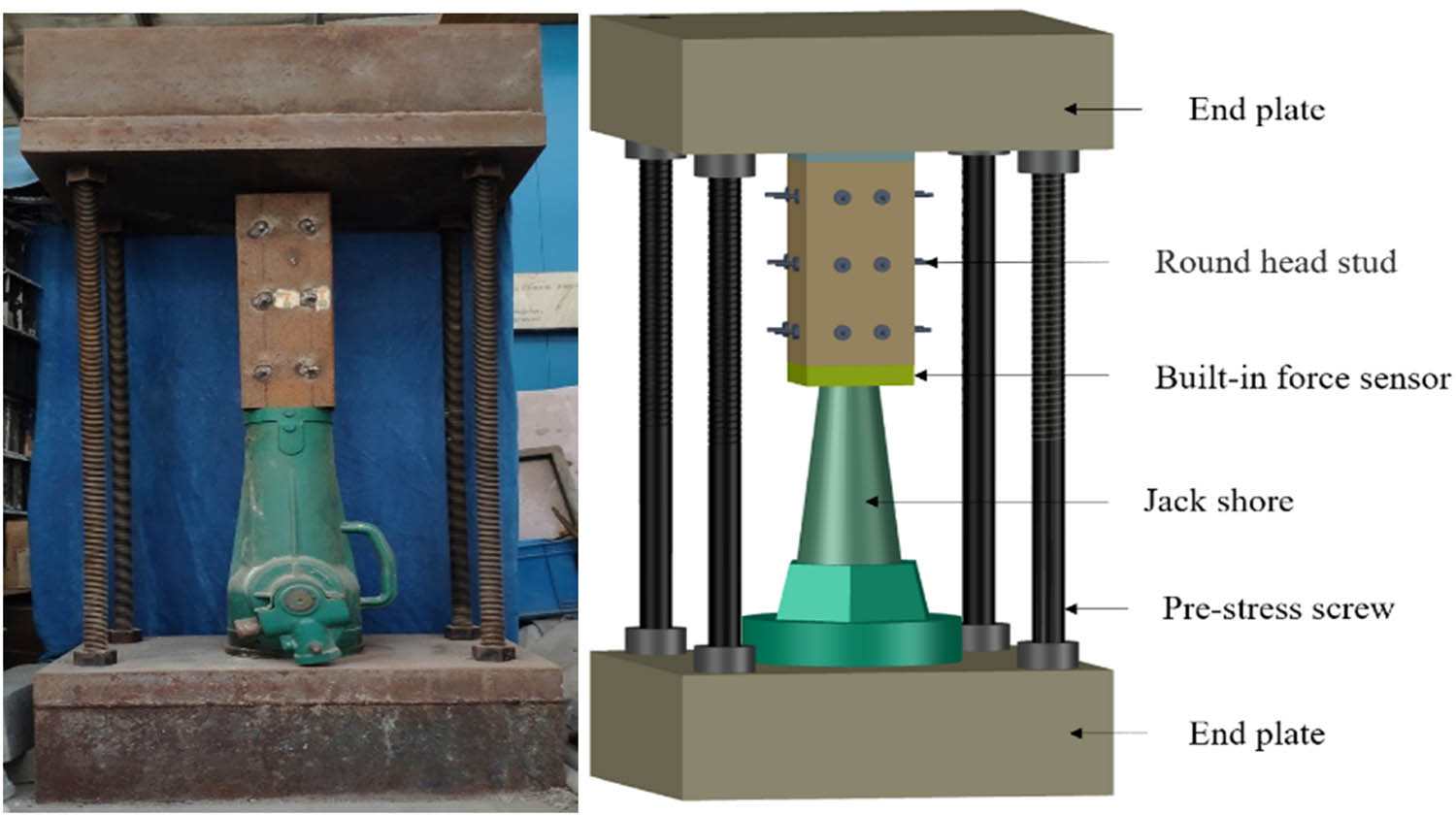
Long-term load testing device.
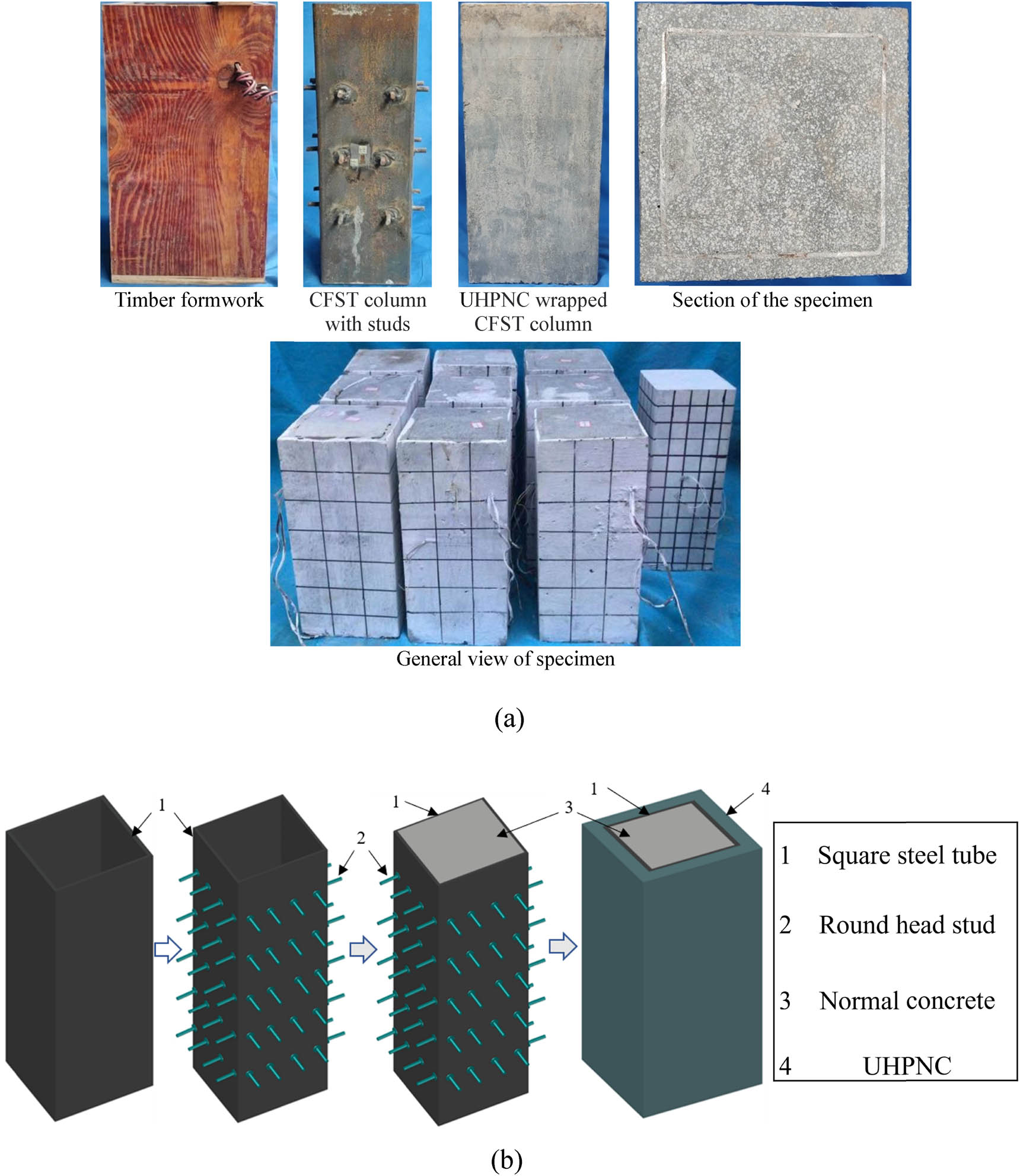
The details of CFST columns strengthened with UHPNC. (a) Sample pouring process and general picture. (b) Flow chart of specimen pouring.
The purpose of this experiment is to research the effect of different thicknesses of UHPNC-reinforced layer [39] and nano-silica [40] content on the bearing capacity of CFST column under long-term continuous load. The CFST column is made of concrete with a strength of 30 MPa, and the square steel tube size is 120 mm × 120 mm × 360 mm. The parameter variables of each specimen in this test are shown in Table 1. In the Table, the CFST represents the rectangular concrete-filled steel tube column, T (thickness) is the thick gauge of UHPNC reinforcement layer, and D (dosage) is the nano-silica content. According to the density calculation formula, the number of kilograms of nano-silica required for 1 cubic meter of super-high-performance nano-concrete can be calculated by multiplying by one percent.
List of specimen parameters
| Specimen label | Normal concrete strength (MPa) | T (mm) | D (%) | Long-term load value (kN) | Load holding time (Day) | Type of reinforcement | Specimen size (mm) |
|---|---|---|---|---|---|---|---|
| CFST-T10-D1 | 30 | 10 | 1 | 550 | 200 | Square | 130 × 130 × 360 |
| CFST-T15-D1 | 30 | 15 | 1 | 550 | 200 | Square | 135 × 135 × 360 |
| CFST-T20-D1 | 30 | 20 | 1 | 550 | 200 | Square | 140 × 140 × 360 |
| CFST-T10-D2 | 30 | 10 | 2 | 550 | 200 | Square | 130 × 130 × 360 |
| CFST-T15-D2 | 30 | 15 | 2 | 550 | 200 | Square | 135 × 135 × 360 |
| CFST-T20-D2 | 30 | 20 | 2 | 550 | 200 | Square | 140 × 140 × 360 |
| CFST-T10-D3 | 30 | 10 | 3 | 550 | 200 | Square | 130 × 130 × 360 |
| CFST-T15-D3 | 30 | 15 | 3 | 550 | 200 | Square | 135 × 135 × 360 |
| CFST-T20-D3 | 30 | 20 | 3 | 550 | 200 | Square | 140 × 140 × 360 |
| CFST-T0-D0 | 30 | — | — | 550 | 200 | — | 120 × 120 × 360 |
2.2 Material properties
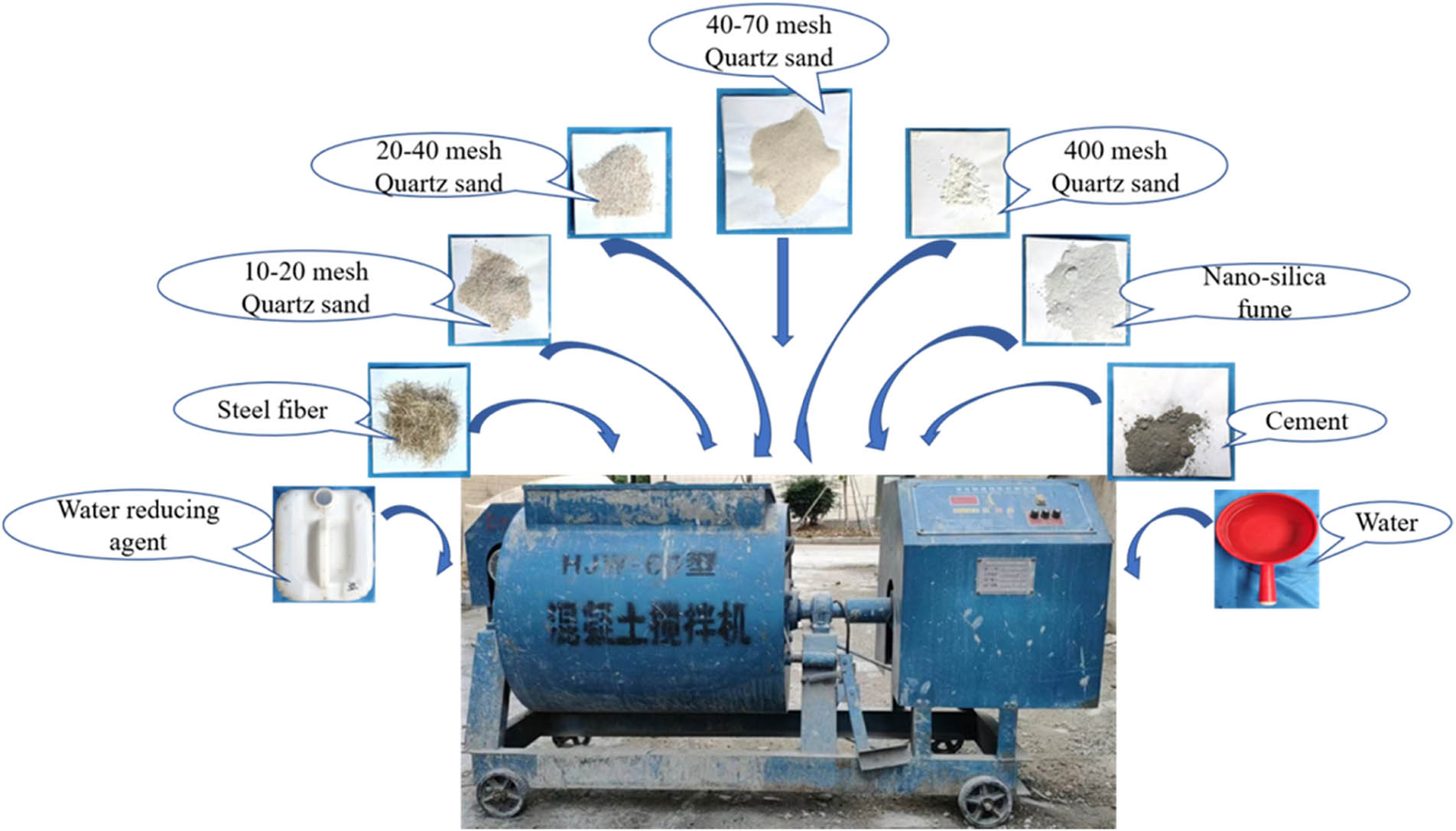
All test specimens were fabricated at the prefabrication yard of Fuzhou University, and UHPNC-reinforced columns were completed under pressure during the fabrication process. 30 MPa is the design strength of concrete and the mix is shown in Table 2. The UHPNC is composed of cement, fine sand, nano-silica fume, steel fiber, water, and water reducer in a certain proportion, as shown in Figure 3. The specific mix proportion of UHPNC is presented in Table 3. Three concrete cubes were used for each kind of concrete to obtain the compressive strength f cu. The size of ordinary concrete cube test block is 150 mm × 150 mm × 150 mm, UHPNC cube test block size is 100 mm × 100 mm × 100 mm. And the concrete used in the test is cured in the same environment as the components, and the specific performance is shown in Table 4. Q235 square steel tube was used in this test. The steel tube thickness is 2.75 mm. To accurately obtain the steel material properties, the tensile test was carried out according to (GB/T228.1-2010). The obtained yield strength (f y), ultimate tensile strength (f u), etc., are shown in Table 5.
Mix proportion of C30 concrete
| Cement (kg/m3) | Water (kg/m3) | Sand (kg/m3) | Coarse aggregate (kg/m3) |
|---|---|---|---|
| 461 | 175 | 512 | 1,250 |
Composition of UHPNC and mixing device.
UHPNC mix proportion
| Cement (kg/m3) | Steel fiber (kg/m3) | Quartz sand (kg/m3) | Water reducing agent (kg/m3) | Water (kg/m3) | Nano-silica fume (kg/m3) | |||
|---|---|---|---|---|---|---|---|---|
| 40–70 mesh | 20–40 mesh | 10–20 mesh | 400 mesh | |||||
| 844.5 | 253.4 | 118.2 | 346.3 | 447.6 | 79.4 | 21.1 | 241.5 | 78 (1%) |
| 156 (2%) | ||||||||
| 234 (3%) | ||||||||
Performance test results of concrete cube material
| D (%) | Serial number | Cubic compressive strength (f cu/MPa) | Average value (f cu/MPa) |
|---|---|---|---|
| 0 (normal concrete) | No. 1 | 34 | 32 |
| No. 2 | 32 | ||
| No. 3 | 30 | ||
| 1 (UHPNC) | No. 1 | 115 | 114 |
| No. 2 | 111 | ||
| No. 3 | 116 | ||
| 2 (UHPNC) | No. 1 | 120 | 121 |
| No. 2 | 124 | ||
| No. 3 | 119 | ||
| 3 (UHPNC) | No. 1 | 127 | 125 |
| No. 2 | 124 | ||
| No. 3 | 124 |
Results of steel properties
| Test coupons | Yield strength (f y/MPa) | Average value (f y/MPa) | Ultimate tensile strength (f u/MPa) | Average value (f u/MPa) |
|---|---|---|---|---|
| No. 1 | 240 | 243 | 428 | 432 |
| No. 2 | 244 | 435 | ||
| No. 3 | 245 | 433 |
2.3 Test process
Combined with the load and size required for loading specific specimens and the existing test equipment in the School of Civil Engineering of Fuzhou University, 10,000 kN servo hydraulic press was selected to carry out the limit loading after load holding, LVDTs are arranged in the position as shown in Figure 4 and built on both sides of the component to test its vertical displacement. A pair of longitudinal and transverse strain gauges are arranged at the centroid of a square CFST column, and a pair of longitudinal and transverse strain gauges are arranged on each side of one of its edges. The reinforced specimens are arranged with a pair of longitudinal and transverse strain gauges on each of the four surfaces as exhibited in Figure 4. To make the full section of the test piece uniformly compressed, before the test loading, grind the loading surface with gypsum, apply a force of 20 kN to the test specimen, and hold the load for 20 min to ensure gypsum solidification. In the formal loading, the axial compression test is first carried out by means of hierarchical loading. Before reaching 70% of the estimated ultimate load, loading at the speed of 0.5 kN/s, the load value is about 1/10 of the estimated ultimate load, and the loading time of each stage lasts for 2–3 min. When the load value exceeds 70% of the estimated ultimate load, the load of each stage is about 1/30 of the estimated ultimate load. The test was stopped until the applied axial load dropped to 85% of the ultimate load or the axial strain exceeded 0.15.
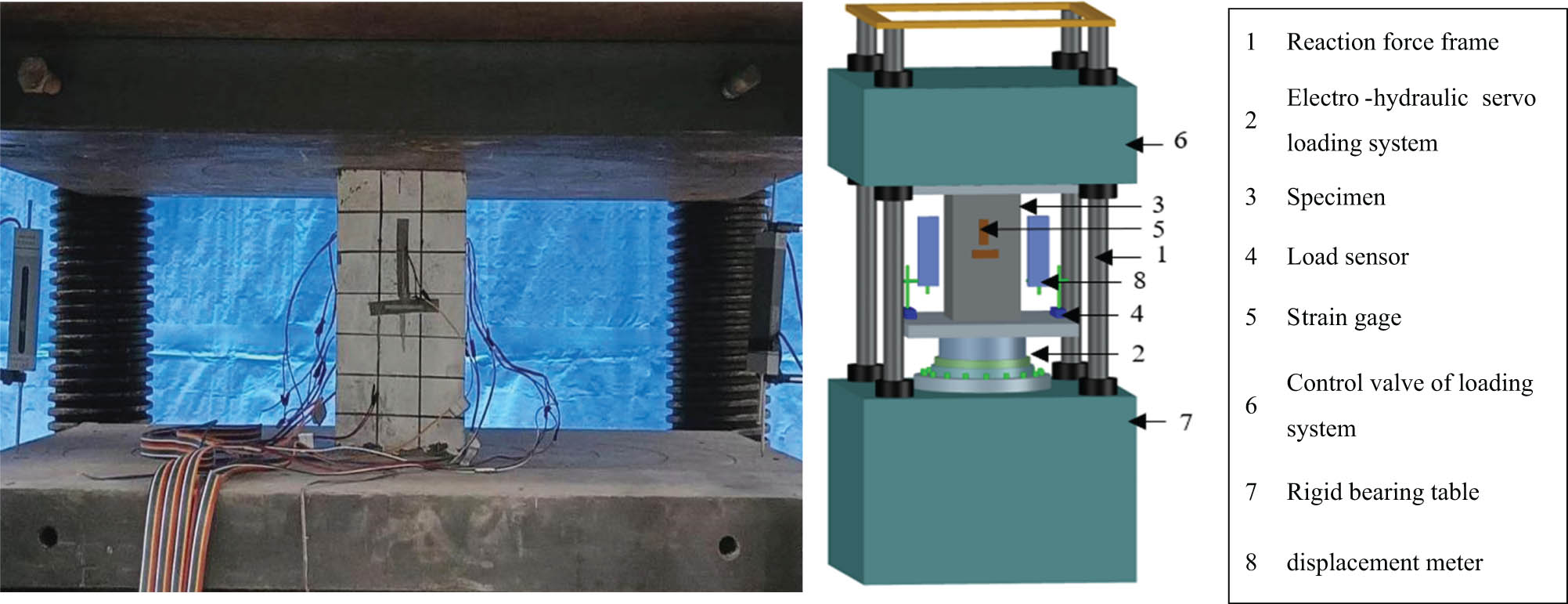
Test specimen under compressive loading.
3 Test result
3.1 Failure modes
According to the failure characteristics of UHPNC-reinforced CFST column under load condition, the failure mode of CFST column was discussed. The failure mode is presented in Figure 5. The results show that the failure process of the initial stage is similar to that of ordinary concrete columns under axial load. The axial deformation of the specimen increased linearly with the increase in the applied loading. And then the axial deformation increased faster than that of the applied loading growth rate. When the applied loading approaches the peak load, the “sizzling” sound of steel fiber pulling out of UHPNC could be heard. When the applied load reached the peak load, the louder sound of “Bang” could be heard. The bearing capacity of the specimen showed a linear decline. The UHPNC reinforcement layer was peeled off the specimen. Although the nano content is different, the failure mode is UHPNC layer shedding, so the component can be considered as failure. After the specimen failed, it could be found that the core concrete of the specimen was compressed. The UHPNC reinforcement layer was peeled off, and the steel tube was significantly deformed. This is mainly because the limit load-bearing capability state of the UHPNC wrapped CFST column was mainly contributed by the UHPNC reinforcement layer. Therefore, the specimen finally shows the failure when the UHPNC reinforcement layer peeled off.
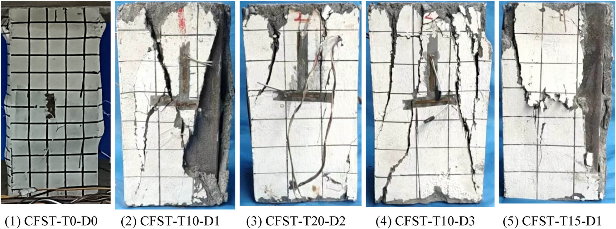
Failure mode of specimens under axial compressive loading.
3.2 Load–displacement curves
The loading and corresponding displacement data collected by the data system of the test device were obtained, and the load–displacement curve of the specimen is shown in Figure 6. In this figure, the vertical axis P is the axial load and the horizontal axis ∆ is the corresponding displacement value. Before the yielding of the test specimen, the displacement increases linearly with the increase in the applied load. When the applied loading was close to the peak load, the corresponding displacement increase rate was greater than the increased rate of the applied loading. Then, the applied loading decreased quickly with a little displacement increase. These load–displacement curves indicated that most specimens were mainly in brittle failure mode under the test. The ultimate bearing capacity (N
u) of the specimen partially increases with the content of nano-silica. With the increase in the thickness of UHPNC reinforcement layer, the increase rate increases greatly. Among other things, the ultimate bearing capacity
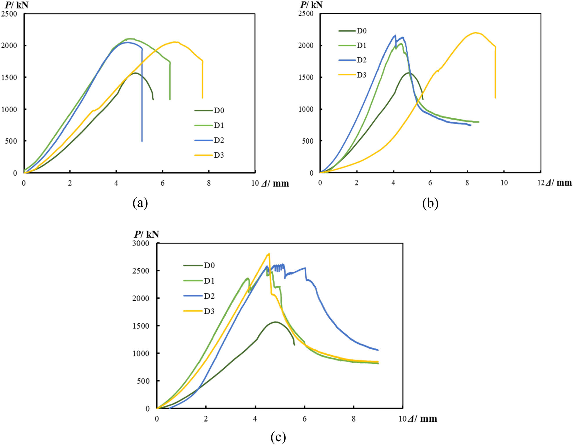
Load–displacement curve of CFST column reinforced by UHPNC. (a) CFST-T10, (b) CFST-T15, and (c) CFST-T20.
Test results of specimen
| Specimen label | Ultimate bearing capacity (kN) | Ultimate displacement (mm) | Yield capacity (kN) | Yield displacement (mm) | Initial stiffness (kN/mm) | Ductility coefficient | Compression toughness (kN mm) |
|---|---|---|---|---|---|---|---|
| CFST-T10-D1 | 2105.80 | 4.59 | 1684.61 | 3.39 | 451.53 | 1.36 | 5031.35 |
| CFST-T15-D1 | 2027.72 | 4.39 | 1622.17 | 3.48 | 316.69 | 1.26 | 3710.74 |
| CFST-T20-D1 | 2544.64 | 4.44 | 2035.71 | 3.19 | 499.23 | 1.39 | 5609.14 |
| CFST-T10-D2 | 2048.40 | 4.5272 | 1638.72 | 3.2896 | 401.89 | 1.38 | 4512.08 |
| CFST-T15-D2 | 2162.54 | 4.10 | 1730.03 | 3.30 | 410.64 | 1.24 | 4733.03 |
| CFST-T20-D2 | 2621.70 | 5.11 | 2093.58 | 3.80 | 382.33 | 1.35 | 5926.74 |
| CFST-T10-D3 | 2055.20 | 6.54 | 1644.16 | 4.88 | 304.28 | 1.34 | 6818.32 |
| CFST-T15-D3 | 2200.02 | 8.45 | 1760.02 | 6.88 | 168.99 | 1.23 | 7451.22 |
| CFST-T20-D3 | 2812.77 | 4.55 | 2250.22 | 3.82 | 455.77 | 1.19 | 5339.22 |
| CFST-T0-D0 | 1564.75 | 4.89 | 1251.82 | 4.10 | 244.22 | 1.19 | 3309.94 |
3.3 Ultimate bearing capacity
The influence of nano-silica content in the UHPNC-reinforced layer on the ultimate bearing capacity of CFST column after use is shown in Figure 7. It can be obviously found that the ultimate bearing capacity of CFST column is greatly improved due to the existence of UHPNC reinforcement layer. For example, when the thickness of UHPNC-reinforced layer reaches 10 mm and the content of nano-silica is 1%, the ultimate bearing capacity of the specimen increases by 42% on average. The results show that this method is an effective method to improve the ultimate bearing capacity of CFST column in the service period. In addition, with the increase in nano-silica content, the ultimate bearing capacity of CFST column increased slightly during the service period. For example, when the nano-silica content was increased from 1 to 2% and from 2 to 3%, the ultimate bearing capacity of the test specimen increased by an average of 2 and 3%, respectively. It could be concluded that the ultimate bearing capacity of CFST columns was greatly affected by the UHPNC reinforcement layer. But the effects of nano-silica content on the ultimate bearing capacity were not obvious. However, when the thickness of UHPNC-reinforced layer is 20, the ultimate bearing capacity is greatly increased, and the role of nano-silica becomes obvious. It can be concluded that with the increase in the thickness of the reinforced layer, the nano content has an obvious effect on the ultimate bearing capacity. It also could be found that the increased rate of ultimate bearing capacity was greatly increased with the increase in UHPNC reinforcement layer thickness.
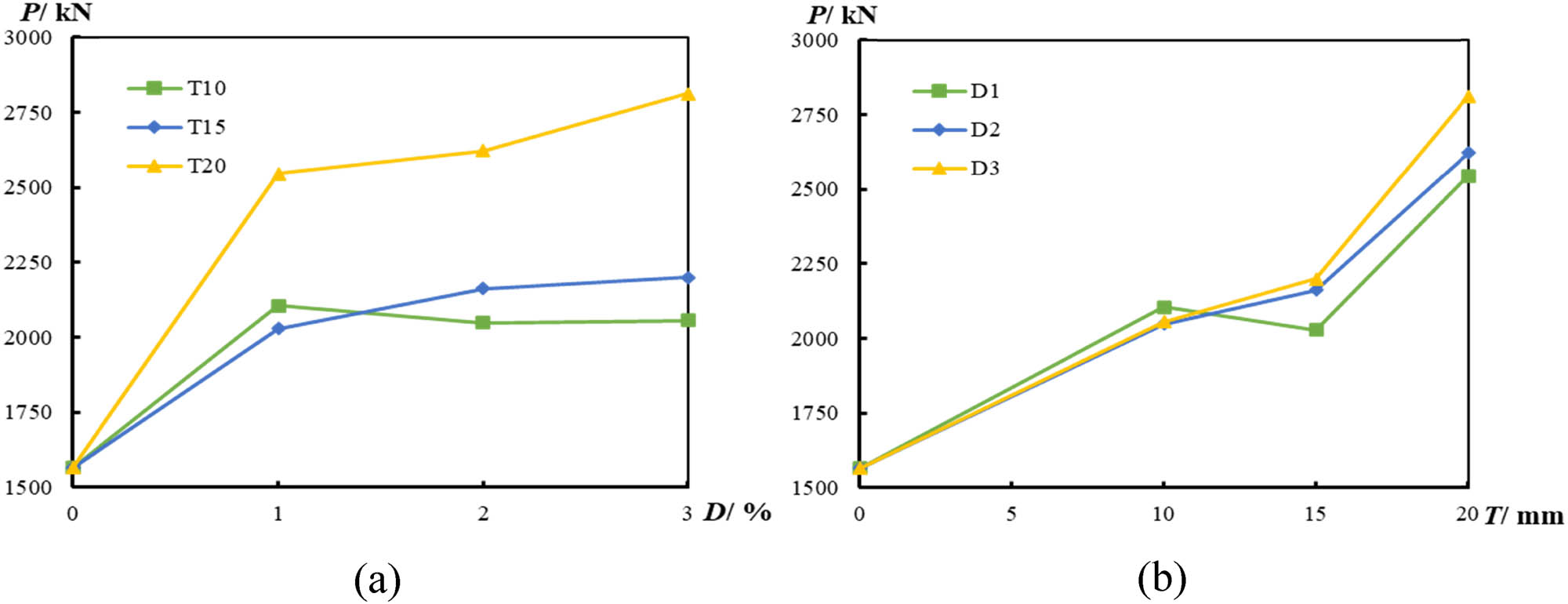
Influence of test variables on ultimate bearing capacity. (a) Influence of nano-silica content and (b) influence of thickness of UHPNC reinforcement layer.
Figure 7 discusses the influence of the thickness of the UHPNC reinforcement layer on the ultimate bearing capacity of CFST under ultimate loading during the service period. With the increase in the thickness of the UHPNC reinforcement layer, the ultimate bearing capacity increases significantly. For example, when the nano-silica content was 2%, the ultimate bearing capacity of the test specimen increased from 2048.40 to 2162.54 kN and from 2162.54 to 2621.70 kN with the increase in UHPNC reinforcement layer thickness from 10 to 15 mm and from 15 to 20 mm, respectively. In general, when the UHPNC reinforcement layer thickness was increased from 10 to 15 mm and from 15 to 20 mm, the ultimate bearing capacity of the test specimen increased by an average of 3 and 25%, respectively. It indicated that the improvement rate of ultimate bearing capacity increased with the increase in UHPNC reinforcement layer thickness. The reason was that the stiffness of the UHPNC reinforcement layer increased with the increase in thickness. Therefore, the thicker UHPNC reinforcement layer could provide a more powerful constraint to the concrete-filled steel tubular column.
3.4 Initial stiffness
The influence of the test parameters on the initial stiffness of the specimen is shown in Figure 8. It could be found that the initial stiffness of the test specimen was greatly increased because of the UHPNC reinforcement layer. For example, the initial stiffness of the test increased by an average of 73% when the UHPNC reinforcement layer was 10 mm and the nano-silica content was 1%. The results show that this method is an effective measure to improve the initial stiffness of CFST column under long-term load. However, the initial stiffness of the test specimen decreased with the increase in nano-silica content. For example, when the UHPNC reinforcement layer thickness was 10 mm, the initial stiffness of the test specimen decreased from 451.53 to 401.89 kN/mm and from 401.89 to 304.28 kN/mm with the increase in the nano-silica content from 1 to 2% and from 2 to 3%, respectively. It could be found that the initial stiffness decrease rate increased with the increase in nano-silica content.
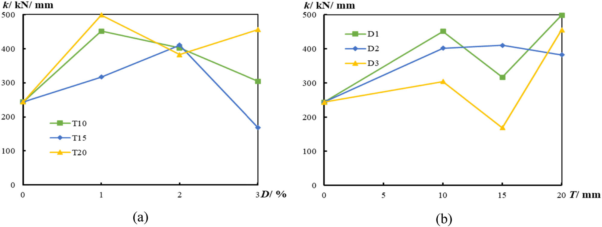
Influence of the test parameters on the initial stiffness of the specimen. (a) Influence of nano-silica content and (b) influence of UHPNC reinforcement layer thickness.
Figure 8 discusses the influence of the thickness of the UHPNC reinforcement layer on the initial stiffness of the specimen during the service period. It could be found that the initial stiffness of the test specimen increased with the increase in the UHPNC reinforcement layer thickness. For example, when the nano-silica content was 1%, the initial stiffness of test specimen increased from 451.53 to 499.23 kN/mm with the increase in UHPNC reinforcement layer thickness from 10 to 20 mm. And the initial stiffness increased from 304.28 to 455.77 kN/mm with the increase in UHPNC reinforcement layer thickness from 10 to 20 mm when the nano-silica content was 3%. The decrease rate of initial stiffness increases with the increase in nano-silica content.
3.5 Ductility coefficient
The ultimate loading experiment results of CFST columns wrapped by UHPNC under long-term sustained load are shown in Table 6. Meanwhile, the value of ductility coefficient μ is calculated according to formula (1).
where Δ u is the ultimate displacement and Δ y is the corresponding yield displacement [41].
Figure 9 discusses the influence of the nano-silica content in the UHPNC reinforcement layer on the ductility coefficient of CFST column during the service period. The ductility coefficient of test specimen increased because of the UHPNC reinforcement layer. For example, the ductility coefficient increased by an average of 12% when the UHPNC reinforcement layer was 10 mm and the nano-silica content was 1%. The results show that using UHPNC to wrap CFST column under long-term load is an effective method to improve the ductility coefficient of CFST column during service period. However, with the increase in nano-silica content, the ductility coefficient of UHPNC components decreases. For example, when the UHPNC reinforcement layer thickness was 20 mm, the ductility coefficient decreased from 1.394 to 1.345 and from 1.345 to 1.191 with the increase in nano-silica content from 1 to 2% and from 2 to 3%, respectively. In general, when the nano-silica content was increased from 1 to 2% and from 2 to 3%, the ductility coefficient decreased by an average of 1 and 5%, respectively. It indicated that the decrease rate of ductility coefficient increased with the increase in nano-silica. But, overall, the effect of nano-silica content on the ductility coefficient was not obvious.
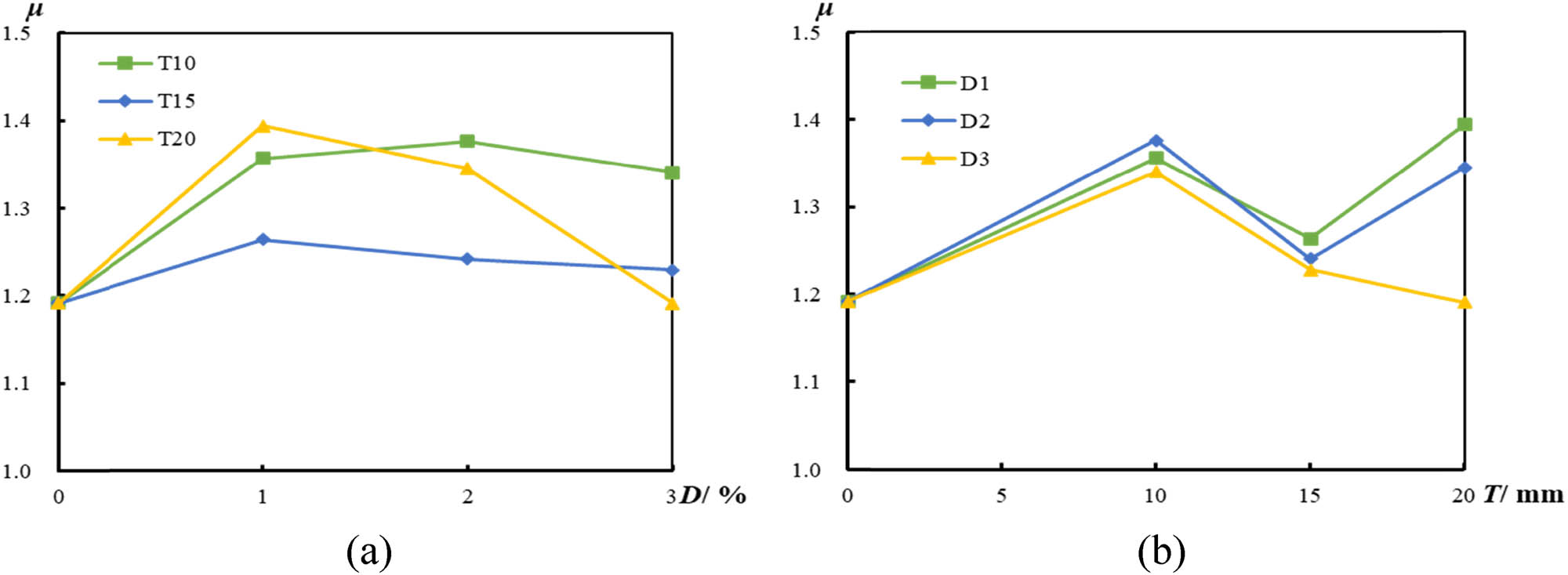
Influence of each test parameter variable on the ductility coefficient. (a) Influence of nano-silica content and (b) influence of UHPNC reinforcement layer thickness.
3.6 Compressive toughness
The compressive toughness is the value of the area under the load–displacement curve before the peak load. The compression toughness represents the energy released when the UHPNC wrapped CFST column is damaged [42,43,44,45]. The compressive toughness can be calculated as follows:
where Δ max is the displacement corresponding to the peak load.
The effects of nano-silica content on the compression toughness of test specimen are presented in Figure 10. It could be found that the compression toughness increased because of the UHPNC-reinforced layer. For example, the compression toughness increased by an average of 45% when the UHPNC reinforcement layer was 10 mm and the nano-silica content was 1%. In addition, the compression toughness increased with the increase in nano-silica content, such that when the UHPNC reinforcement layer thickness was 15 mm, the compression toughness of the test specimen increased from 3710.74 to 4733.03 kN mm and from 4733.03 to 7451.22 kN mm with the increase in of nano-silica content from 1 to 2% and from 2 to 3%, respectively. The reason may be that more energy was needed to pull out the nano-silica from the fracture surface because of the increasing nano-silica content.
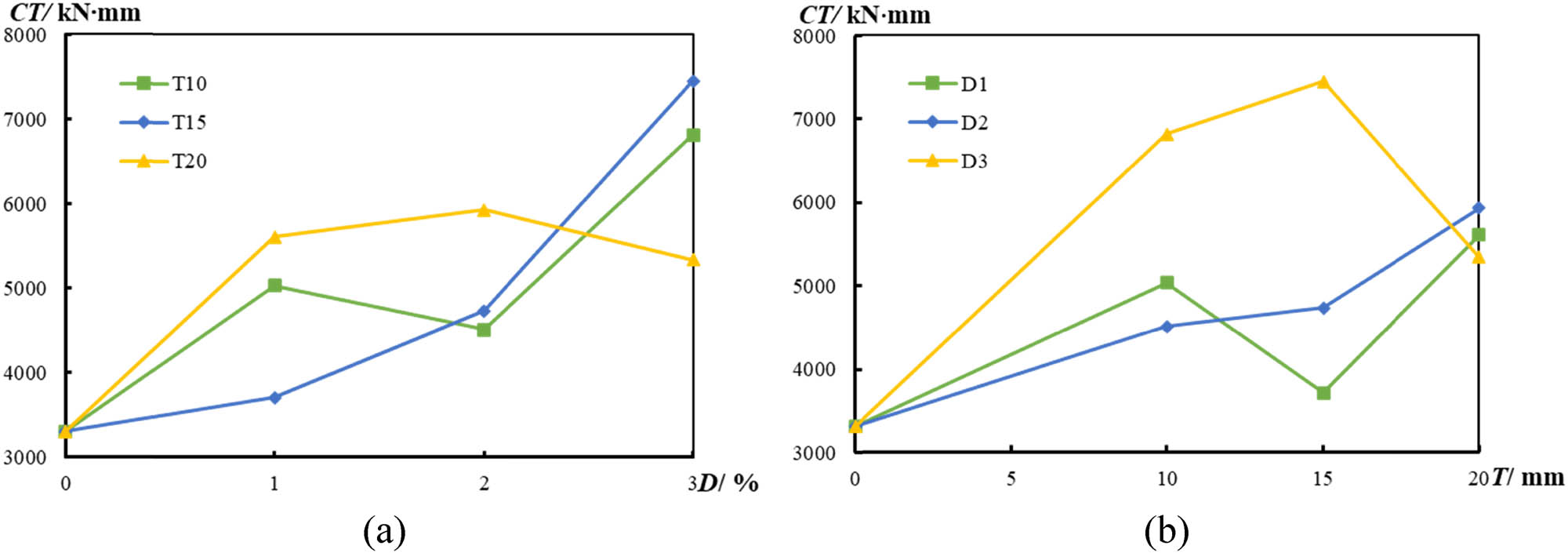
Influence of test variables on compressive toughness. (a) Influence of nano-silica content and (b) influence of UHPNC reinforcement layer thickness.
In Figure 10, the effects of UHPNC reinforcement layer thickness on the compression toughness were discussed. It could be found that the compression toughness increased with the increase in UHPNC reinforcement layer thickness. For example, when the nano-silica content was 2%, the compression toughness increased from 4512.08 to 4733.03 kN mm and from 4733.03 to 5926.74 kN mm with the increase in UHPNC reinforcement layer thickness from 15 to 20 mm.
4 Formula to calculate ultimate bearing capability
A new comprehensive calculation method is used to calculate the ultimate bearing capacity (N uc) of CFST column under axial compression load under long-term loading condition of UHPNC wrap. The effects of nano-silica content and UHPNC reinforcement layer thickness must be considered while calculating the ultimate bearing capacity. The ultimate bearing capacity of UHPN- reinforced columns subjected to axial compressive loading was calculated by introducing the influence coefficient (η) of test parameters. The assumed functional forms of the calculation formula are as follows:
where the A s, A c, and A u were the cross-sectional area of steel, normal concrete, and UHPNC, respectively. f(α) and f(β) are the functions of α and β, respectively. The T 0 was 10 mm and D 0 was 1 (%).
The calculation value (N uc) of the CFST column under UHPNC reinforcement is compared with the statistical results of the test value, which proves the rationality and accuracy of the formula. As can be seen from Table 7, the calculated limit capacity values of most specimens are smaller than those of the test results. The mean value is 0.98, and the variance is 0.03, which indicates that the equation is reasonable and accurate in predicting the ultimate bearing capacity of CFST column strengthened by UHPNC under load holding state.
Calculation results of ultimate bearing capacity of specimen
| Specimen label | N u (kN) | N ue (kN) | T (mm) | D (%) | α | β | N uc (kN) | N uc /N u | Error (%) |
|---|---|---|---|---|---|---|---|---|---|
| CFST-T10-D1 | 2105.80 | 1950.02 | 10 | 1 | 1.0 | 1 | 1906.81 | 0.91 | −9 |
| CFST-T15-D1 | 2027.72 | 2305.70 | 15 | 1 | 1.5 | 1 | 2215.24 | 1.09 | 9 |
| CFST-T20-D1 | 2544.64 | 2661.38 | 20 | 1 | 2.0 | 1 | 2511.53 | 0.99 | −1 |
| CFST-T10-D2 | 2048.40 | 1993.70 | 10 | 2 | 1.0 | 2 | 1929.47 | 0.94 | −6 |
| CFST-T15-D2 | 2162.54 | 2371.22 | 15 | 2 | 1.5 | 2 | 2252.32 | 1.04 | 4 |
| CFST-T20-D2 | 2621.70 | 2748.74 | 20 | 2 | 2.0 | 2 | 2563.01 | 0.98 | −2 |
| CFST-T10-D3 | 2055.20 | 2018.66 | 10 | 3 | 1.0 | 3 | 1931.29 | 0.94 | −6 |
| CFST-T15-D3 | 2200.02 | 2408.66 | 15 | 3 | 1.5 | 3 | 2261.60 | 1.03 | 3 |
| CFST-T20-D3 | 2812.77 | 2798.66 | 20 | 3 | 2.0 | 3 | 2578.04 | 0.92 | −8 |
| Mean value | — | — | — | — | — | — | — | 0.98 | −2 |
| Variance | — | — | — | — | — | — | — | 0.003 | 0.003 |
5 Conclusion
The effects of UHPNC reinforcement layer thickness and nano-silica content on the compressive properties of CFST column under load holding condition were studied. This study discussed the failure modes, load–displacement curves, ultimate bearing capacity, initial stiffness, ductility coefficient, and compression toughness. The following conclusions are obtained from this study:
The ultimate bearing capacity, initial stiffness, ductility coefficient, and compressive toughness of CFST column under load holding state are improved by UHPNC reinforcement layer. The results show that the outsourced UHPNC reinforcement method is an effective method to improve the performance of CFST columns during service period.
The ultimate bearing capacity of CFST column is greatly increased with the increase in UHPNC reinforcement layer thickness. And the improvement rate of ultimate bearing capacity is increased with the increase in UHPNC reinforcement layer thickness. However, the effect of nano-silica content on the ultimate bearing capacity is not obvious.
During the service period, the initial stiffness of CFST column increases with the increase in the thickness of UHPNC reinforcement layer and decreases with the increase in nano-silica content. The decrease rate of initial stiffness increases with the increase in nano-silica content.
The ductility coefficient of CFST column decreased with the increase in nano-silica content. And the decrease rate of ductility coefficient increased with the increase in nano-silica content. In addition, the compression toughness increases with the increase in nano-silica content and UHPNC reinforcement layer thickness.
According to the test results, a reasonable and conservative formula for calculating the ultimate compressive capacity of CFST column under long-term constant load reinforced by UHPNC is put forward. The calculated results are in good agreement with the experimental results.
-
Funding information: This research work was supported by National Natural Science Foundation of China (No. 52078138), the Guiding Project of Fujian Province (No. 2021Y0003), the Science and Technology Planning Project of Fuzhou (No. 2021-Y-083), The Fifth Batch of Science and Technology Plan Project of Housing and Urban-Rural Construction Industry of Fujian Province in 2022 (No. 2022-K-296), and Project of the twenty-eighth Undergraduate Scientific Research Training Program of Fuzhou University (No. 28130).
-
Author contributions: All authors have accepted responsibility for the entire content of this manuscript and approved its submission.
-
Conflict of interest: The authors state no conflict of interest.
References
[1] Wu Z. Green high performance concrete - the trend of concrete development. China Concr Cem Products. 1998;1:3–6.Search in Google Scholar
[2] Chen BC, Ji T, Huang QW, Wu HZ, Ding QJ, Zhan YW. Review of research on ultra-high performance concrete. J Archit Civ Eng. 2014;31(3):1–24.Search in Google Scholar
[3] Richard P, Cheyrezy M. Composition of reactive powder concretes. Cem Concr Res. 1995;25(7):1501–11.10.1016/0008-8846(95)00144-2Search in Google Scholar
[4] Li Y, Xie H, Peng Q, Zhu J. Progress in mechanic property and design theory of elementary structure of reactive powder concrete (RPC). Adv Mech. 2011;41(1):51–9.Search in Google Scholar
[5] De LF, Sedran T. Optimization of ultra-high-performance concrete by the use of a packing model. Cem Concr Res. 1994;24(6):997–1009.Search in Google Scholar
[6] Yazici H. The effect of curing conditions on compressive strength of ultra high strength concrete with high volume mineral admixtures. Build Env. 2006;42(5):2083–9.10.1016/j.buildenv.2006.03.013Search in Google Scholar
[7] Soutsos M, Millard S, Karaiskos K. Mix design, mechanical properties, and impact resistance of reactive powder concrete (RPC). International Workshop on High Performance Fibre-Reinforced Cementitious Composites in Structural Applications; 2005. p. 549–60.Search in Google Scholar
[8] Li S, Cheng S, Mo L, Deng M. Effects of steel slag powder and expansive agent on the properties of ultra-high performance concrete (UHPC): Based on a case study. Materials. 2020;13(3):683.10.3390/ma13030683Search in Google Scholar PubMed PubMed Central
[9] Su J, Fang Z. Scale effect on cubic compressive strength of ordinary concrete and high-strength concrete. J Build Mater. 2013;16(6):1078–81.Search in Google Scholar
[10] Chen X, Wu S, Zhou J. Variability of compressive strength of concrete cores. J Perform Constr Facil. 2014;28(4):06014001.10.1061/(ASCE)CF.1943-5509.0000513Search in Google Scholar
[11] Wang D, Shi C, Wu Z, Xiao J, Huang Z, Fang Z. A review on ultra high performance concrete: Part II. hydration, micro-structure and properties. Constr Build Mater. 2015;96:368–77.10.1016/j.conbuildmat.2015.08.095Search in Google Scholar
[12] Roux N, Andrade C, Sanjuan MA. Experimental study of durability of reactive powder concretes. J Mater Civ Eng. 1996;8(1):1–6.10.1061/(ASCE)0899-1561(1996)8:1(1)Search in Google Scholar
[13] Graybeal B. Material property characterization of ultra-high performance concrete. FHWA-HRT-06-103. United States: Federal Highway Administration. Department of Transportation; 2006. p. 176.Search in Google Scholar
[14] De Larrard F, Sedran T. Optimization of ultra-high-performance concrete by the use of a packing model. Cem Concr Res. 1994;24(6):997–1009.10.1016/0008-8846(94)90022-1Search in Google Scholar
[15] Schmidt M, Fehling E. Ultra-high-performance concrete: Research, development and application in Europe. 7th International Symposium on Utilization of High Strength High Performance Concrete. Vol. 1; 2005. p. 51–77.Search in Google Scholar
[16] Vernet P. Ultra-durable concretes: Structure at the micro- and nano-scale. Mater Res Soc. 2004;29(5):324–7.10.1557/mrs2004.98Search in Google Scholar
[17] Wille K, Naaman A, Montesinos G. Ultra-high performance concrete with compressive strength exceeding 150 MPa (22 ksi): A simpler way. ACI Mater J. 2011;108(1):46–54.10.14359/51664215Search in Google Scholar
[18] Li ZH, Xu K, Wei F. Recent progress in photodetectors based on low-dimensional nanomaterials. Nanotechnol Rev. 2018;7(5):393–411.10.1515/ntrev-2018-0084Search in Google Scholar
[19] Pawłowski R, Pawłowski B, Wita H, Pluta A, Sobik P, Sala A, et al. Silver nanoparticles in the thermal silver plating of aluminium busbar joints. Nanotechnol Rev. 2018;7(5):365–72.10.1515/ntrev-2018-0032Search in Google Scholar
[20] Zhang HL. Selective modification of inner surface of halloysite nanotubes: A review. Nanotechnol Rev. 2017;6(6):573–81.10.1515/ntrev-2017-0163Search in Google Scholar
[21] Lin Q, Chen Y, Liu C. Mechanical properties of circular nano-silica concrete filled stainless steel tube stub columns after being exposed to freezing and thawing. Nanotechnol Rev. 2019;8:600–18.10.1515/ntrev-2019-0053Search in Google Scholar
[22] Genedy M. A new CFRP-UHPC system for strengthening reinforced concrete T-beams. Department of Energy. UNM’s Digital Repository; 2014.Search in Google Scholar
[23] Katrin H, Emmanuel D, Eugen B. Experimental investigation of composite ultra high-performance fiber-reinforced concrete and conventional concrete members. Struct J. 2007;104:93–101.10.14359/18437Search in Google Scholar
[24] Prem PR, Ramachandra Murthy A, Ramesh G, Bharatkumar BH, Iyer NR. Flexural behaviour of damaged RC beams strengthened with ultra high performance concrete. In: Matsagar V, editor. Advances in Structural Engineering. Springer; 2015. p. 2057–69.10.1007/978-81-322-2187-6_158Search in Google Scholar
[25] Lampropoulos AP, Paschalis SA, Tsioulou OT, Dritsos SE. Strengthening of reinforced concrete beams using ultra high performance fibre reinforced concrete (UHPFRC). Eng Struct. 2016;106:370–84.10.1016/j.engstruct.2015.10.042Search in Google Scholar
[26] Al-Osta MA, Isa MN, Baluch MH, Rahman MK. Flexural behavior of reinforced concrete beams strengthened with ultra-high performance fiber reinforced concrete. Constr Build Mater. 2017;134:279–96.10.1016/j.conbuildmat.2016.12.094Search in Google Scholar
[27] Beschi C, Meda A, Riva P. Column and joint retrofitting with high performance fiber reinforced concrete jacketing. Appl Mech Mater. 2011;82(7):989–1014.10.1080/13632469.2011.552167Search in Google Scholar
[28] Lee MG, Huang YS. Fire-Damage or freeze-thaw of strengthening concrete using ultra high performance concrete. Adv Mater Res. 2009;79–82:2047–50.10.4028/www.scientific.net/AMR.79-82.2047Search in Google Scholar
[29] Tayeh BA, Bakar BHA, Johari MAM, Voo YL. Mechanical and permeability properties of the interface between normal concrete substrate and ultra high performance fiber concrete overlay. Constr Build Mater. 2012;36:538–48.10.1016/j.conbuildmat.2012.06.013Search in Google Scholar
[30] Huang K, Xie J, Wang R, Feng Y, Rao R. Effects of the combined usage of nanomaterials and steel fibres on the workability, compressive strength, and microstructure of ultra-high performance concrete. Nanotechnol Rev. 2021;10(1):304–17.10.1515/ntrev-2021-0029Search in Google Scholar
[31] Luo Q, Wu Y, Qiu W, Huang H, Pei S, Lambert P, et al. Improving flexural strength of UHPC with sustainably synthesized graphene oxide. Nanotechnol Rev. 2021;10(1):754–67.10.1515/ntrev-2021-0050Search in Google Scholar
[32] Liu C, He X, Deng X, Wu Y, Zheng Z, Liu J, et al. Application of nanomaterials in ultra-high performance concrete: A review. Nanotechnol Rev. 2020;9(1):1427–44.10.1515/ntrev-2020-0107Search in Google Scholar
[33] Bonneau O, Lachemi M, Dallaire E, Dugat J, Aitcin P. Mechanical properties and durability of two industrial reactive powder concretes. ACI Mater J. 1997;94(4):286–90.10.14359/310Search in Google Scholar
[34] Reda M, Shrive G, Gillott E. Microstructural investigation of innovative UHPC. Cem Concr Res. 1999;29(3):323–9.10.1016/S0008-8846(98)00225-7Search in Google Scholar
[35] Schmidt M, Fehling E, Teichmann T, Bunje K, Bornemann R. Ultra-high performance concrete: Perspective for the precast concrete industry. Concr Pre-Casting Plant Technol. 2003;69(3):16–29.Search in Google Scholar
[36] Herold G, Muller H. Measurement of porosity of ultra-high strength fibre-reinforced concrete. Proceedings of the International Symposium on Ultra-High Performance Concrete; 2004. p. 685–94.Search in Google Scholar
[37] Jun P, Taek K, Tae K, Wook K. Influence of the ingredients on the compressive strength of UHPC as a fundamental study to optimize the mixing proportion. Proceedings of the 2nd International Symposium on ultra High Performance Concrete; 2008. p. 105–12.Search in Google Scholar
[38] Ma DY, Han LH, Li W, Hou C, Mu TM. Behaviour of concrete-encased CFST stub columns subjected to long-term sustained loading. J Constr Steel Res. 2018;151:58–69.10.1016/j.jcsr.2018.09.016Search in Google Scholar
[39] Graybeal B, Davis M. Cylinder or cube: Strength testing of 80–200 MPa (11.6–29 ksi) ultra high performance fibre-reinforced concrete. ACI Mater J. 2008;105(6):603–9.10.14359/20202Search in Google Scholar
[40] Bayard O, Ple O. Fracture mechanics of reactive powder concrete: Material modeling and experimental investigations. Eng Fract Mech. 2003;70(7–8):839–51.10.1016/S0013-7944(02)00153-4Search in Google Scholar
[41] Zhang XY, Xia C, Chen Y. Research on nano-concrete-filled steel tubular columns with end plates after lateral impact. Rev Adv Mater Sci. 2021;60(1):553–66.10.1515/rams-2021-0044Search in Google Scholar
[42] Poon CS, Shui ZH, Lam L. Compressive behavior of fiber reinforced high performance concrete subjected to elevated temperatures. Cem Concr Res. 2004;34(12):2215–22.10.1016/j.cemconres.2004.02.011Search in Google Scholar
[43] Taerwe L, AVan G. Influence of steel fibers on design stress-strain curve for high strength concrete. J Eng Mech. 1996;122:695–704.10.1061/(ASCE)0733-9399(1996)122:8(695)Search in Google Scholar
[44] Nataraja MC, Dhang N, Gupta AP. Stress-strain curves for steel-fiber reinforced concrete under compression. Cem Concr Compos. 1999;21:383–90.10.1016/S0958-9465(99)00021-9Search in Google Scholar
[45] Xiaoyong Z, Shihan C, Zhouhua W, Huiyun Q, Guixing L, Xiaolei W, Yu C. Research on mechanical properties of ultra-high performance fiber reinforced cement-based composite after elevated temperature. Compos Struct. 2022;291:115584.10.1016/j.compstruct.2022.115584Search in Google Scholar
© 2023 the author(s), published by De Gruyter
This work is licensed under the Creative Commons Attribution 4.0 International License.
Articles in the same Issue
- Research Articles
- Preparation of CdS–Ag2S nanocomposites by ultrasound-assisted UV photolysis treatment and its visible light photocatalysis activity
- Significance of nanoparticle radius and inter-particle spacing toward the radiative water-based alumina nanofluid flow over a rotating disk
- Aptamer-based detection of serotonin based on the rapid in situ synthesis of colorimetric gold nanoparticles
- Investigation of the nucleation and growth behavior of Ti2AlC and Ti3AlC nano-precipitates in TiAl alloys
- Dynamic recrystallization behavior and nucleation mechanism of dual-scale SiCp/A356 composites processed by P/M method
- High mechanical performance of 3-aminopropyl triethoxy silane/epoxy cured in a sandwich construction of 3D carbon felts foam and woven basalt fibers
- Applying solution of spray polyurea elastomer in asphalt binder: Feasibility analysis and DSR study based on the MSCR and LAS tests
- Study on the chronic toxicity and carcinogenicity of iron-based bioabsorbable stents
- Influence of microalloying with B on the microstructure and properties of brazed joints with Ag–Cu–Zn–Sn filler metal
- Thermohydraulic performance of thermal system integrated with twisted turbulator inserts using ternary hybrid nanofluids
- Study of mechanical properties of epoxy/graphene and epoxy/halloysite nanocomposites
- Effects of CaO addition on the CuW composite containing micro- and nano-sized tungsten particles synthesized via aluminothermic coupling with silicothermic reduction
- Cu and Al2O3-based hybrid nanofluid flow through a porous cavity
- Design of functional vancomycin-embedded bio-derived extracellular matrix hydrogels for repairing infectious bone defects
- Study on nanocrystalline coating prepared by electro-spraying 316L metal wire and its corrosion performance
- Axial compression performance of CFST columns reinforced by ultra-high-performance nano-concrete under long-term loading
- Tungsten trioxide nanocomposite for conventional soliton and noise-like pulse generation in anomalous dispersion laser cavity
- Microstructure and electrical contact behavior of the nano-yttria-modified Cu-Al2O3/30Mo/3SiC composite
- Melting rheology in thermally stratified graphene-mineral oil reservoir (third-grade nanofluid) with slip condition
- Re-examination of nonlinear vibration and nonlinear bending of porous sandwich cylindrical panels reinforced by graphene platelets
- Parametric simulation of hybrid nanofluid flow consisting of cobalt ferrite nanoparticles with second-order slip and variable viscosity over an extending surface
- Chitosan-capped silver nanoparticles with potent and selective intrinsic activity against the breast cancer cells
- Multi-core/shell SiO2@Al2O3 nanostructures deposited on Ti3AlC2 to enhance high-temperature stability and microwave absorption properties
- Solution-processed Bi2S3/BiVO4/TiO2 ternary heterojunction photoanode with enhanced photoelectrochemical performance
- Electroporation effect of ZnO nanoarrays under low voltage for water disinfection
- NIR-II window absorbing graphene oxide-coated gold nanorods and graphene quantum dot-coupled gold nanorods for photothermal cancer therapy
- Nonlinear three-dimensional stability characteristics of geometrically imperfect nanoshells under axial compression and surface residual stress
- Investigation of different nanoparticles properties on the thermal conductivity and viscosity of nanofluids by molecular dynamics simulation
- Optimized Cu2O-{100} facet for generation of different reactive oxidative species via peroxymonosulfate activation at specific pH values to efficient acetaminophen removal
- Brownian and thermal diffusivity impact due to the Maxwell nanofluid (graphene/engine oil) flow with motile microorganisms and Joule heating
- Appraising the dielectric properties and the effectiveness of electromagnetic shielding of graphene reinforced silicone rubber nanocomposite
- Synthesis of Ag and Cu nanoparticles by plasma discharge in inorganic salt solutions
- Low-cost and large-scale preparation of ultrafine TiO2@C hybrids for high-performance degradation of methyl orange and formaldehyde under visible light
- Utilization of waste glass with natural pozzolan in the production of self-glazed glass-ceramic materials
- Mechanical performance of date palm fiber-reinforced concrete modified with nano-activated carbon
- Melting point of dried gold nanoparticles prepared with ultrasonic spray pyrolysis and lyophilisation
- Graphene nanofibers: A modern approach towards tailored gypsum composites
- Role of localized magnetic field in vortex generation in tri-hybrid nanofluid flow: A numerical approach
- Intelligent computing for the double-diffusive peristaltic rheology of magneto couple stress nanomaterials
- Bioconvection transport of upper convected Maxwell nanoliquid with gyrotactic microorganism, nonlinear thermal radiation, and chemical reaction
- 3D printing of porous Ti6Al4V bone tissue engineering scaffold and surface anodization preparation of nanotubes to enhance its biological property
- Bioinspired ferromagnetic CoFe2O4 nanoparticles: Potential pharmaceutical and medical applications
- Significance of gyrotactic microorganisms on the MHD tangent hyperbolic nanofluid flow across an elastic slender surface: Numerical analysis
- Performance of polycarboxylate superplasticisers in seawater-blended cement: Effect from chemical structure and nano modification
- Entropy minimization of GO–Ag/KO cross-hybrid nanofluid over a convectively heated surface
- Oxygen plasma assisted room temperature bonding for manufacturing SU-8 polymer micro/nanoscale nozzle
- Performance and mechanism of CO2 reduction by DBD-coupled mesoporous SiO2
- Polyarylene ether nitrile dielectric films modified by HNTs@PDA hybrids for high-temperature resistant organic electronics field
- Exploration of generalized two-phase free convection magnetohydrodynamic flow of dusty tetra-hybrid Casson nanofluid between parallel microplates
- Hygrothermal bending analysis of sandwich nanoplates with FG porous core and piezomagnetic faces via nonlocal strain gradient theory
- Design and optimization of a TiO2/RGO-supported epoxy multilayer microwave absorber by the modified local best particle swarm optimization algorithm
- Mechanical properties and frost resistance of recycled brick aggregate concrete modified by nano-SiO2
- Self-template synthesis of hollow flower-like NiCo2O4 nanoparticles as an efficient bifunctional catalyst for oxygen reduction and oxygen evolution in alkaline media
- High-performance wearable flexible strain sensors based on an AgNWs/rGO/TPU electrospun nanofiber film for monitoring human activities
- High-performance lithium–selenium batteries enabled by nitrogen-doped porous carbon from peanut meal
- Investigating effects of Lorentz forces and convective heating on ternary hybrid nanofluid flow over a curved surface using homotopy analysis method
- Exploring the potential of biogenic magnesium oxide nanoparticles for cytotoxicity: In vitro and in silico studies on HCT116 and HT29 cells and DPPH radical scavenging
- Enhanced visible-light-driven photocatalytic degradation of azo dyes by heteroatom-doped nickel tungstate nanoparticles
- A facile method to synthesize nZVI-doped polypyrrole-based carbon nanotube for Ag(i) removal
- Improved osseointegration of dental titanium implants by TiO2 nanotube arrays with self-assembled recombinant IGF-1 in type 2 diabetes mellitus rat model
- Functionalized SWCNTs@Ag–TiO2 nanocomposites induce ROS-mediated apoptosis and autophagy in liver cancer cells
- Triboelectric nanogenerator based on a water droplet spring with a concave spherical surface for harvesting wave energy and detecting pressure
- A mathematical approach for modeling the blood flow containing nanoparticles by employing the Buongiorno’s model
- Molecular dynamics study on dynamic interlayer friction of graphene and its strain effect
- Induction of apoptosis and autophagy via regulation of AKT and JNK mitogen-activated protein kinase pathways in breast cancer cell lines exposed to gold nanoparticles loaded with TNF-α and combined with doxorubicin
- Effect of PVA fibers on durability of nano-SiO2-reinforced cement-based composites subjected to wet-thermal and chloride salt-coupled environment
- Effect of polyvinyl alcohol fibers on mechanical properties of nano-SiO2-reinforced geopolymer composites under a complex environment
- In vitro studies of titanium dioxide nanoparticles modified with glutathione as a potential drug delivery system
- Comparative investigations of Ag/H2O nanofluid and Ag-CuO/H2O hybrid nanofluid with Darcy-Forchheimer flow over a curved surface
- Study on deformation characteristics of multi-pass continuous drawing of micro copper wire based on crystal plasticity finite element method
- Properties of ultra-high-performance self-compacting fiber-reinforced concrete modified with nanomaterials
- Prediction of lap shear strength of GNP and TiO2/epoxy nanocomposite adhesives
- A novel exploration of how localized magnetic field affects vortex generation of trihybrid nanofluids
- Fabrication and physicochemical characterization of copper oxide–pyrrhotite nanocomposites for the cytotoxic effects on HepG2 cells and the mechanism
- Thermal radiative flow of cross nanofluid due to a stretched cylinder containing microorganisms
- In vitro study of the biphasic calcium phosphate/chitosan hybrid biomaterial scaffold fabricated via solvent casting and evaporation technique for bone regeneration
- Insights into the thermal characteristics and dynamics of stagnant blood conveying titanium oxide, alumina, and silver nanoparticles subject to Lorentz force and internal heating over a curved surface
- Effects of nano-SiO2 additives on carbon fiber-reinforced fly ash–slag geopolymer composites performance: Workability, mechanical properties, and microstructure
- Energy bandgap and thermal characteristics of non-Darcian MHD rotating hybridity nanofluid thin film flow: Nanotechnology application
- Green synthesis and characterization of ginger-extract-based oxali-palladium nanoparticles for colorectal cancer: Downregulation of REG4 and apoptosis induction
- Abnormal evolution of resistivity and microstructure of annealed Ag nanoparticles/Ag–Mo films
- Preparation of water-based dextran-coated Fe3O4 magnetic fluid for magnetic hyperthermia
- Statistical investigations and morphological aspects of cross-rheological material suspended in transportation of alumina, silica, titanium, and ethylene glycol via the Galerkin algorithm
- Effect of CNT film interleaves on the flexural properties and strength after impact of CFRP composites
- Self-assembled nanoscale entities: Preparative process optimization, payload release, and enhanced bioavailability of thymoquinone natural product
- Structure–mechanical property relationships of 3D-printed porous polydimethylsiloxane films
- Nonlinear thermal radiation and the slip effect on a 3D bioconvection flow of the Casson nanofluid in a rotating frame via a homotopy analysis mechanism
- Residual mechanical properties of concrete incorporated with nano supplementary cementitious materials exposed to elevated temperature
- Time-independent three-dimensional flow of a water-based hybrid nanofluid past a Riga plate with slips and convective conditions: A homotopic solution
- Lightweight and high-strength polyarylene ether nitrile-based composites for efficient electromagnetic interference shielding
- Review Articles
- Recycling waste sources into nanocomposites of graphene materials: Overview from an energy-focused perspective
- Hybrid nanofiller reinforcement in thermoset and biothermoset applications: A review
- Current state-of-the-art review of nanotechnology-based therapeutics for viral pandemics: Special attention to COVID-19
- Solid lipid nanoparticles for targeted natural and synthetic drugs delivery in high-incidence cancers, and other diseases: Roles of preparation methods, lipid composition, transitional stability, and release profiles in nanocarriers’ development
- Critical review on experimental and theoretical studies of elastic properties of wurtzite-structured ZnO nanowires
- Polyurea micro-/nano-capsule applications in construction industry: A review
- A comprehensive review and clinical guide to molecular and serological diagnostic tests and future development: In vitro diagnostic testing for COVID-19
- Recent advances in electrocatalytic oxidation of 5-hydroxymethylfurfural to 2,5-furandicarboxylic acid: Mechanism, catalyst, coupling system
- Research progress and prospect of silica-based polymer nanofluids in enhanced oil recovery
- Review of the pharmacokinetics of nanodrugs
- Engineered nanoflowers, nanotrees, nanostars, nanodendrites, and nanoleaves for biomedical applications
- Research progress of biopolymers combined with stem cells in the repair of intrauterine adhesions
- Progress in FEM modeling on mechanical and electromechanical properties of carbon nanotube cement-based composites
- Antifouling induced by surface wettability of poly(dimethyl siloxane) and its nanocomposites
- TiO2 aerogel composite high-efficiency photocatalysts for environmental treatment and hydrogen energy production
- Structural properties of alumina surfaces and their roles in the synthesis of environmentally persistent free radicals (EPFRs)
- Nanoparticles for the potential treatment of Alzheimer’s disease: A physiopathological approach
- Current status of synthesis and consolidation strategies for thermo-resistant nanoalloys and their general applications
- Recent research progress on the stimuli-responsive smart membrane: A review
- Dispersion of carbon nanotubes in aqueous cementitious materials: A review
- Applications of DNA tetrahedron nanostructure in cancer diagnosis and anticancer drugs delivery
- Magnetic nanoparticles in 3D-printed scaffolds for biomedical applications
- An overview of the synthesis of silicon carbide–boron carbide composite powders
- Organolead halide perovskites: Synthetic routes, structural features, and their potential in the development of photovoltaic
- Recent advancements in nanotechnology application on wood and bamboo materials: A review
- Application of aptamer-functionalized nanomaterials in molecular imaging of tumors
- Recent progress on corrosion mechanisms of graphene-reinforced metal matrix composites
- Research progress on preparation, modification, and application of phenolic aerogel
- Application of nanomaterials in early diagnosis of cancer
- Plant mediated-green synthesis of zinc oxide nanoparticles: An insight into biomedical applications
- Recent developments in terahertz quantum cascade lasers for practical applications
- Recent progress in dielectric/metal/dielectric electrodes for foldable light-emitting devices
- Nanocoatings for ballistic applications: A review
- A mini-review on MoS2 membrane for water desalination: Recent development and challenges
- Recent updates in nanotechnological advances for wound healing: A narrative review
- Recent advances in DNA nanomaterials for cancer diagnosis and treatment
- Electrochemical micro- and nanobiosensors for in vivo reactive oxygen/nitrogen species measurement in the brain
- Advances in organic–inorganic nanocomposites for cancer imaging and therapy
- Advancements in aluminum matrix composites reinforced with carbides and graphene: A comprehensive review
- Modification effects of nanosilica on asphalt binders: A review
- Decellularized extracellular matrix as a promising biomaterial for musculoskeletal tissue regeneration
- Review of the sol–gel method in preparing nano TiO2 for advanced oxidation process
- Micro/nano manufacturing aircraft surface with anti-icing and deicing performances: An overview
- Cell type-targeting nanoparticles in treating central nervous system diseases: Challenges and hopes
- An overview of hydrogen production from Al-based materials
- A review of application, modification, and prospect of melamine foam
- A review of the performance of fibre-reinforced composite laminates with carbon nanotubes
- Research on AFM tip-related nanofabrication of two-dimensional materials
- Advances in phase change building materials: An overview
- Development of graphene and graphene quantum dots toward biomedical engineering applications: A review
- Nanoremediation approaches for the mitigation of heavy metal contamination in vegetables: An overview
- Photodynamic therapy empowered by nanotechnology for oral and dental science: Progress and perspectives
- Biosynthesis of metal nanoparticles: Bioreduction and biomineralization
- Current diagnostic and therapeutic approaches for severe acute respiratory syndrome coronavirus-2 (SARS-COV-2) and the role of nanomaterial-based theragnosis in combating the pandemic
- Application of two-dimensional black phosphorus material in wound healing
- Special Issue on Advanced Nanomaterials and Composites for Energy Conversion and Storage - Part I
- Helical fluorinated carbon nanotubes/iron(iii) fluoride hybrid with multilevel transportation channels and rich active sites for lithium/fluorinated carbon primary battery
- The progress of cathode materials in aqueous zinc-ion batteries
- Special Issue on Advanced Nanomaterials for Carbon Capture, Environment and Utilization for Energy Sustainability - Part I
- Effect of polypropylene fiber and nano-silica on the compressive strength and frost resistance of recycled brick aggregate concrete
- Mechanochemical design of nanomaterials for catalytic applications with a benign-by-design focus