Re-examination of nonlinear vibration and nonlinear bending of porous sandwich cylindrical panels reinforced by graphene platelets
-
 and
and

Abstract
This article re-examines the nonlinear vibration and nonlinear bending responses of porous sandwich cylindrical panels reinforced by graphene platelets resting on elastic foundations in thermal environments. The graphene platelet-reinforced composite (GPLRC) core is assumed to be of multilayers, and each layer may have different porosity coefficient values to achieve a piece-wise functionally graded pattern. By introducing an inhomogeneous model instead of the equivalent isotropic model (EIM), the Young’s moduli along with the shear modulus of the porous GPLRC core are predicted through a generic Halpin–Tsai model in which the porosity is included. The thermomechanical properties of metal face sheets and the porous GPLRC core are assumed to be temperature-dependent. Governing equations of motion for sandwich cylindrical panels with porous GPLRC core are formulated based on Reddy’s third-order shear deformation theory coupled with von Kármán nonlinear strain–displacement relationships. In the modeling, the panel–foundation interaction and the thermal effects are also considered. The analytical solutions for the nonlinear vibration and nonlinear bending problems are obtained by applying a two-step perturbation approach. Numerical studies are performed to compare the results obtained from the present model and the EIM. The results confirm that the EIM is not suitable for linear free vibration analysis of sandwich cylindrical panels with the porous GPLRC core, but the EIM may be valid for the cases of nonlinear vibration and nonlinear bending analyses of the same panel resting on Pasternak elastic foundations.
Graphical abstract
1 Introduction
Porous materials are realized as a new class of advanced engineering materials characterized by low density, electrical conductivity, great energy absorption capability, and thermal resistance [1,2,3,4]. However, the presence of porosities in the metal matrix will lead to a significant reduction in terms of structural stiffness [5,6,7,8]. With the development of nanotechnology and additive manufacturing technology [9,10], nanofillers such as carbon nanotubes (CNTs) [11] or graphene platelets (GPLs) [12] can be added into porous metal foams to increase the stiffness of porous metal materials while maintaining the lightweight nature of foams. GPL can be regarded as an isotropic solid, which consists of a large number of stacked monolayer graphene. GPL-reinforced porous metal foams may be created as particle-reinforced composites where GPLs are uniformly or randomly dispersed in the porous metal foams. The mechanical performance of the porous metal materials reinforced by GPLs may be enhanced substantially while maintaining the lightweight advantage of the porous metal materials.
Many studies have been carried out on the static and dynamic analyses of porous GPL-reinforced composite (GPLRC) flat panels without or with face sheets [13,14,15,16,17,18,19,20,21,22,23,24]. However, relatively few studies have been done on the static and dynamic analyses of porous GPLRC cylindrical panels. In order to enhance the mechanical performance of porous metal panels, it is an effective approach to incorporate the functionally graded (FG) material concept [25] into the design of the porous metal panel. Zhou et al. [26] investigated vibration and flutter characteristics of porous FG-GPLRC cylindrical panels subjected to supersonic flow based on Reddy’s third-order shear deformation theory (TSDT) and by applying the standard Lagrange procedure. Similar to the flat panels, the porous GPLRC cylindrical panels cannot be used as structural components directly in engineering practice. It is a better way to add two face sheets on the outer and inner surfaces of the porous GPLRC layer to create a sandwich panel where the porous GPLRC layer is treated as a hard core, and in that case the Reddy’s TSDT is still valid. Twinkle and Pitchaimani [27,28] studied the effects of grading, porosity, and non-uniform edge loads on the natural frequency and buckling load of porous FG-GPLRC cylindrical panels and sandwich cylindrical panels with the porous FG-GPLRC core based on the higher-order shear deformation theory (HSDT) and by applying the Galerkin method. Sun et al. [29] calculated free vibration frequencies of sandwich cylindrical panels with the porous FG-GPLRC core based on the Love shell theory and by applying the Ritz method. In the aforementioned works, the equivalent isotropic model (EIM) was adopted to determine the equivalent Young’s modulus of the GPLRC layer through a modified Halpin–Tsai model and the shear modulus is assumed to be related to the Young’s modulus by a well-known formula of isotropic material.
It has been reported that, even for the GPLRC flat panel without porosity, the shear modulus will be underestimated by using the EIM [30]. Shen and his co-authors [31,32] proposed an inhomogeneous model instead of the EIM and re-examined the linear and nonlinear vibration and the nonlinear bending along with the buckling and postbuckling responses of porous sandwich plates reinforced by GPLs. They found that the shear modulus is overestimated when the porosity coefficient is less than 0.2, while underestimated when the porosity coefficient is greater than 0.25 by using the EIM. Their results reveal that, owing to the shear modulus effect, for most cases, the difference in the natural frequencies between the two models is over 30%. The nonlinear free vibration frequency–amplitude curves, the nonlinear bending load–deflection curves, and the thermal postbuckling load–deflection curves are always underestimated, while the compressive postbuckling equilibrium paths of the porous sandwich plates are always overestimated by using the EIM. Only in the case of porous sandwich plates resting on Pasternak elastic foundations with sufficiently large foundation stiffnesses, the difference between the two models may be negligible, and the EIM may be valid in the analysis.
The purpose of this article is to evaluate the appropriateness of applying the EIM in vibration and bending analyses of porous GPLRC cylindrical panels. We re-examine the nonlinear vibration and the nonlinear bending of sandwich cylindrical panels with metal face sheets and porous GPLRC core resting on elastic foundations in thermal environments. We choose two kinds of porous GPLRC core in the present study, i.e., uniformly distributed (UD) and piece-wise FG patterns. The material properties of both metal face sheets and porous GPLRC core are assumed to be temperature-dependent. The novelty of this study is that an inhomogeneous model is introduced instead of the EIM for the porous GPLRC core, where the Young’s moduli along with the shear modulus are predicted through a generic Halpin–Tsai model in which the porosity is included. Governing equations of motion for porous sandwich cylindrical panels are formulated based on Reddy’s TSDT coupled with the von Kármán nonlinear strain–displacement relationships. In the modeling, the panel–foundation interaction and thermal effect are also considered. By applying a two-step perturbation approach to solve these equations, the analytical solutions for the two cases of nonlinear vibration and nonlinear bending problems of porous sandwich cylindrical panels are obtained. Numerical comparisons are performed to show the differences between the current model and the EIM.
2 Modeling of porous sandwich cylindrical panels
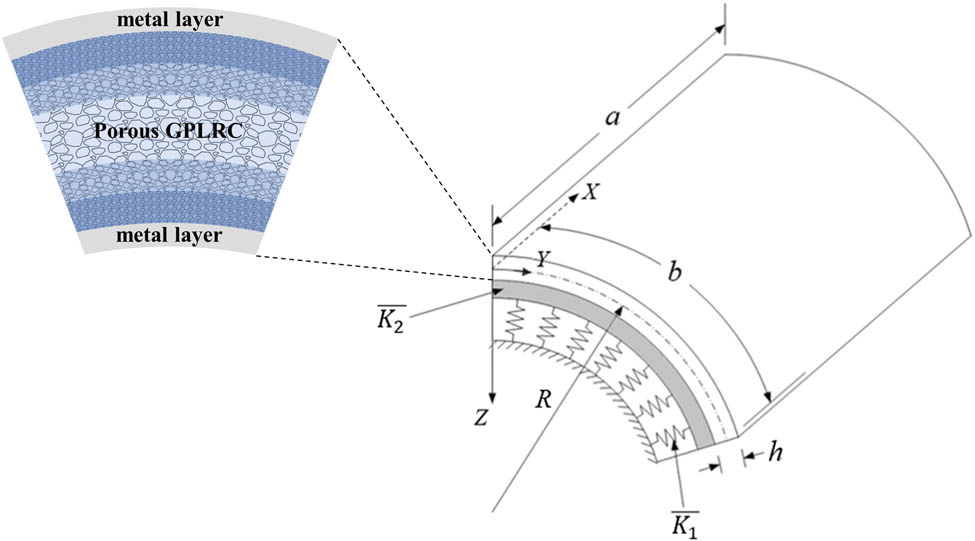
Consider a porous sandwich cylindrical panel with outer and inner face sheets made of titanium alloy and a core made of aluminum foams reinforced by GPLs. The GPLRC core consists of six layers. Each layer of the porous GPLRC core may have different porosity values and, therefore, the piece-wise FG distribution patterns of porosities across the panel thickness can be achieved. Consider a coordinate system (X, Y, Z) with its origin located at one corner of the panel on the mid-plane, where X and Y are placed in the axial and circumferential directions, and Z is pointed inward and placed in the panel thickness direction (Figure 1). The panel is of length a in the X direction, length b in the Y direction, the radius of curvature R, and total thickness h. The thickness of the GPLRC core is h
c, while the thickness of each metal face sheet is h
f. The panel is resting on an elastic foundation that is idealized as a Pasternak-type model with two stiffnesses, where

Geometry and the coordinate system of a porous cylindrical panel resting on a Pasternak elastic foundation.
The key issue for analyzing the mechanical response of the GPLRC structures successfully is to determine the material properties of the GPLRC layer accurately and effectively. Since the porous metal foam is slightly anisotropic [33,34], in particular, the shear modulus does not obey the well-known formula of an isotropic material, we introduce an inhomogeneous model instead of the EIM for the porous GPLRC core, where the Young’s moduli E 11 and E 22 along with the shear modulus G 12 of the porous GPLRC layer are determined by a generic Halpin–Tsai model [35]:
where a
GPL is the length, b
GPL is the width, and h
GPL is the thickness of the GPL; in addition,
in which E GPL and G GPL are the Young’s and shear moduli of the GPL, and E m and G m are the Young’s and shear moduli of the porous metal matrix.
The mass density and Poisson’s ratio of each porous GPLRC layer may be predicted by the rule of the mixture model:
where
For a GPLRC layer without porosity, the volume fraction relationship V GPL + V m = 1 is valid, whereas the relationship V GPL + V m = 1 is invalid for porous metal foams, as reported in Shen and Li [36]. For this reason, we remove the relationship V GPL + V m = 1 for the porous GPLRC layer, and assume that
where
with
For a porous GPLRC layer, the weight fractions still follow the relationship w GPL + w m = 1. Hence, the relationships between the weight fractions (w GPL, w m) and the volume fractions (V GPL, V m) for a porous GPLRC layer can be written as
In the previous studies [13,14,15,16,17,18,19,20,21,22,23,24,26,27,28,29], the Young’s modulus E
m of the porous matrix is assumed to obey the Gibson–Ashby model [37], and Poisson’s ratio
The main difference between the present model compared with the EIM is that the Young’s modulus E
m, the shear modulus G
m, and Poisson’s ratio
in which E
M is the Young’s modulus, G
M is the shear modulus, and
The panel is subjected to a transverse dynamic load q(X, Y,
where
and other linear operators
In equation (9a)–(9d), the superposed dots indicate differentiation with respect to time, and the inertias
and
where
in which
in which
where E
11, E
22, G
12,
We assume that the four edges of a porous sandwich cylindrical panel are simply supported without or with in-plane displacements, referred to as ‘immovable’ or ‘movable’ edges, respectively. The associated boundary conditions are given by
in which
Meanwhile, the in-plane boundary conditions on the X = (0, a) edges are
and the in-plane boundary conditions on the Y = (0, b) edges are
in which
The immovability conditions of equations (16a) and (17a) may be fulfilled in the average sense as
or
In the above equations, the reduced stiffness matrices, such as
where the panel stiffnesses A ij , B ij ,… are given by
and the inertias
where
where c 1 = 4/(3h 2).
3 Solution procedure
A two-step perturbation method was developed in Shen [43]. This approach is successfully employed to solve various nonlinear boundary-value problems of curved panels [44,45,46,47,48,49,50,51,52]. To apply this two-step perturbation approach to solve nonlinear vibration and nonlinear bending problems of porous sandwich cylindrical panels, the motion equations (9a)–(9d) are first re-written in the non-dimensional forms as
where
and the other non-dimensional L ij ( ) and L( ) are given in Shen and Xiang [41]. In these equations, the non-dimensional parameters are given by
in which
The simply supported boundary conditions of equations (15a) and (15b) can be re-written in non-dimensional forms as
and the in-plane boundary conditions on the x = (0, π) edges become
and the in-plane boundary conditions on the y = (0, π) edges become
3.1 Nonlinear vibration solutions for porous sandwich cylindrical panels
To explore the nonlinear vibration problem, we need to determine the relationship between the frequency and vibration amplitude of the porous sandwich cylindrical panel. By applying the two-step perturbation approach, the asymptotic solutions of equations (24a)–(24d) satisfying boundary conditions (equations (28a) and (28b)–(30a) and (30b)) are obtained as
It is worth noting that in equations (31)–(35),
For the free vibration problem of the panel, the dynamic load vanishes and we have
In the second step, we take
where
3.2 Nonlinear bending solutions for porous sandwich cylindrical panels
For the nonlinear bending problem, we need to determine the relationship between the applied pressure and central deflection of the porous sandwich cylindrical panel. In the present case, the applied pressure is static and uniform and is taken to be
in which
Substituting equation (39) into equation (38), the load–central deflection relationship can be obtained. In equation (38),
4 Numerical results and discussion
In this section, the evaluation is made through the free vibration natural frequencies, the nonlinear-to-linear frequency ratio curves, and the nonlinear bending load–deflection curves. The free vibration natural frequencies and the nonlinear-to-linear frequency ratio curves are obtained from equation (37), while the nonlinear bending load–deflection curves are obtained from equations (38) and (39). The reliability and accuracy of the present solution method have been validated by many comparison studies with other research teams using different methods [41,53,54,55]. In the current research, numerical studies are performed to compare the results obtained from the present model and the EIM, where the equivalent Young’s modulus is predicted by a modified Halpin–Tsai model [22].
in which E 11 and E 22 have the same forms of equation (1a) and (1b), and the shear modulus is expressed by
in which
where V
m = 1 − V
GPL and E
m and
The thermomechanical properties of the metal face sheets and the porous GPLRC core have to be determined first. We select titanium alloy (referred to as Ti–6Al–4V) for the metal face sheets, and the temperature-dependent material properties of Ti–6Al–4V are as follows [25]: E
Ti = 122.56 × (1.0 − 4.586 × 10⁻⁴
T) GPa,
For the porous GPLRC core, the dimension of the GPL is set as a
GPL = 2.5 μm, b
GPL = 1.5 μm, and h
GPL
= 1.5 nm. Through a literature survey study, we found that the linear fitting formulae
In the present study, the GPL weight fraction
Volume fractions of the porous GPLRC layer with different porosity coefficients
|
|
(V GPL, V m) | |||
|---|---|---|---|---|
|
|
|
|
|
|
| 0.01 | (0.0155, 0.7845) | (0.0088, 0.5912) | (0.0039, 0.3961) | (0.001, 0.199) |
| 0.02 | (0.0307, 0.7693) | (0.0175, 0.5825) | (0.0078, 0.3922) | (0.002, 0.198) |
| 0.03 | (0.0457, 0.7543) | (0.0261, 0.5739) | (0.0118, 0.3882) | (0.003, 0.197) |
In the current study, the sandwich cylindrical panel has a total thickness h = 0.05 m, while the thickness of the face sheet is 1 mm. The porous GPLRC core consists of six layers and the thickness of each layer is equal to 8 mm. To conduct a six-layer porous GPLRC core with a piece-wise FG pattern, the porosity coefficient in each layer is selected as

A porous GPLRC core: (a) UD, (b) FG-O, and (c) FG-X.
4.1 Vibration characteristics of porous sandwich cylindrical panels
We next focus on the linear and nonlinear vibrations of sandwich cylindrical panels with a porous GPLRC core resting on elastic foundations in thermal environments. The in-plane boundary conditions are set as “immovable.” The sandwich panels have a/b = 1, b/h = 20, and a/R = 0.2, 0.5, and 0.8. Typical results are shown in Tables 2–4 and Figures 3–6, in which the non-dimensional frequency is defined by
Natural frequency
| w GPL |
|
|
|
|
|
|
||
|---|---|---|---|---|---|---|---|---|
| 0.01 | UD | Present model | 8.2011 | 15.8791 | 17.6890 | 25.5357 | 30.7112 | 31.9889 |
| EIMa | 6.4727 | 12.7184 | 14.1066 | 20.2790 | 24.6440 | 25.6230 | ||
| Differenceb | 21.08% | 19.90% | 20.25% | 20.59% | 19.76% | 19.90% | ||
| FG-O | Present model | 7.6483 | 13.8134 | 15.9581 | 22.6151 | 26.6173 | 28.1634 | |
| EIM | 6.1225 | 11.2003 | 12.9311 | 18.0503 | 21.8444 | 23.0738 | ||
| Difference | 19.95% | 18.92% | 18.97% | 20.18% | 17.93% | 18.07% | ||
| FG-X | Present model | 8.9972 | 18.1325 | 19.8045 | 28.7035 | 34.9736 | 36.1468 | |
| EIM | 7.4225 | 15.0236 | 16.3520 | 23.6690 | 28.6817 | 29.6270 | ||
| Difference | 17.50% | 17.15% | 17.43% | 17.54% | 17.99% | 18.04% | ||
| 0.02 | UD | Present model | 8.6836 | 17.0489 | 19.0376 | 27.0124 | 33.2275 | 34.6933 |
| EIM | 7.2340 | 14.0798 | 15.6978 | 22.4806 | 27.3054 | 28.4472 | ||
| Difference | 16.69% | 17.42% | 17.54% | 16.78% | 17.82% | 18.00% | ||
| FG-O | Present model | 8.0365 | 14.6577 | 17.0214 | 23.6886 | 28.4762 | 30.2547 | |
| EIM | 6.7926 | 12.2208 | 14.2416 | 19.7256 | 23.8308 | 25.2705 | ||
| Difference | 15.48% | 16.63% | 16.33% | 16.73% | 16.31% | 16.47% | ||
| FG-X | Present model | 9.5731 | 19.5847 | 21.3979 | 30.5573 | 37.9584 | 39.2849 | |
| EIM | 8.2944 | 16.7188 | 18.2450 | 26.3835 | 31.9832 | 33.0676 | ||
| Difference | 13.36% | 14.63% | 14.73% | 13.66% | 15.74% | 15.83% | ||
| 0.03 | UD | Present model | 9.1050 | 18.1279 | 20.2431 | 28.3839 | 35.5124 | 37.1270 |
| EIM | 7.9194 | 15.3131 | 17.1339 | 24.4711 | 29.7111 | 30.9968 | ||
| Difference | 13.02% | 15.53% | 15.36% | 13.79% | 16.34% | 16.51% | ||
| FG-O | Present model | 8.3729 | 15.4525 | 17.9767 | 24.7030 | 30.2102 | 32.1753 | |
| EIM | 7.4007 | 13.1625 | 15.4393 | 21.2679 | 25.6619 | 27.2876 | ||
| Difference | 11.61% | 14.82% | 14.11% | 13.91% | 15.06% | 15.19% | ||
| FG-X | Present model | 10.0828 | 20.9029 | 22.8166 | 32.2517 | 40.6130 | 42.0622 | |
| EIM | 9.0760 | 18.2391 | 19.9410 | 28.8130 | 34.9349 | 36.1432 | ||
| Difference | 9.99% | 12.74% | 12.60% | 10.66% | 13.98% | 14.07% |
aEIM = equivalent isotropic model.
bDifference = 100%[
Natural frequency
|
|
|
|
|
|
|
|
||
|---|---|---|---|---|---|---|---|---|
| 0 | UD | Present model | 11.4800 | 18.3571 | 23.3051 | 29.2218 | 35.5434 | 39.4425 |
| EIMa | 10.0678 | 15.5124 | 19.7960 | 25.2393 | 29.7367 | 32.9255 | ||
| Differenceb | 12.30% | 15.50% | 15.06% | 13.63% | 16.34% | 16.52% | ||
| FG-O | Present model | 10.9894 | 15.7311 | 21.4879 | 25.6980 | 30.2481 | 34.9283 | |
| EIM | 9.8658 | 13.4173 | 18.6208 | 22.2358 | 25.6946 | 29.6745 | ||
| Difference | 10.22% | 14.71% | 13.34% | 13.47% | 15.05% | 15.04% | ||
| FG-X | Present model | 12.3373 | 21.1087 | 25.6613 | 33.0151 | 40.6411 | 44.1897 | |
| EIM | 11.1753 | 18.4235 | 22.4892 | 29.5329 | 34.9589 | 37.9736 | ||
| Difference | 9.42% | 12.72% | 12.36% | 10.55% | 13.98% | 14.07% | ||
| 100 | UD | Present model | 10.0044 | 16.3137 | 21.2590 | 26.7716 | 33.2817 | 36.8454 |
| EIM | 8.6848 | 13.2599 | 17.9844 | 22.9536 | 27.2794 | 30.6460 | ||
| Difference | 13.19% | 18.72% | 15.40% | 14.26% | 18.03% | 16.83% | ||
| FG-O | Present model | 9.2473 | 12.9703 | 19.0883 | 22.6668 | 27.3175 | 31.8615 | |
| EIM | 8.2881 | 10.4680 | 16.4978 | 19.3914 | 22.5982 | 26.9371 | ||
| Difference | 10.37% | 19.29% | 13.57% | 14.45% | 17.28% | 15.46% | ||
| FG-X | Present model | 10.7738 | 18.9980 | 23.5754 | 30.5029 | 38.2357 | 41.5578 | |
| EIM | 9.7800 | 16.2971 | 20.6841 | 27.3112 | 32.5731 | 35.7134 | ||
| Difference | 9.22% | 14.22% | 12.26% | 10.46% | 14.81% | 14.06% | ||
| 200 | UD | Present model | 8.2206 | 13.8587 | 18.9734 | 24.0079 | 30.7349 | 34.0399 |
| EIM | 7.0334 | 10.5339 | 15.9664 | 20.4111 | 24.5747 | 28.1799 | ||
| Difference | 14.44% | 23.99% | 15.85% | 14.98% | 20.04% | 17.22% | ||
| FG-O | Present model | 7.0132 | 9.2216 | 16.2986 | 19.0527 | 23.8479 | 28.4350 | |
| EIM | 6.3247 | 6.2468 | 14.0533 | 16.0442 | 18.9971 | 23.8822 | ||
| Difference | 9.82% | 32.26% | 13.78% | 15.79% | 20.34% | 16.01% | ||
| FG-X | Present model | 8.8810 | 16.5016 | 21.2537 | 27.6882 | 35.5424 | 38.7218 | |
| EIM | 8.1464 | 13.8440 | 18.7023 | 24.8881 | 29.9938 | 33.2960 | ||
| Difference | 8.27% | 16.11% | 12.00% | 10.11% | 15.61% | 14.01% |
aEIM = equivalent isotropic model.
bDifference = 100% [
Natural frequency
| (k 1 ,k 2) |
|
|
|
|
|
|
||
|---|---|---|---|---|---|---|---|---|
| (0, 0) | UD | Present model | 6.7422 | 15.7720 | 16.0868 | 25.1109 | 30.6978 | 30.9303 |
| EIMa | 5.3650 | 12.6362 | 12.8698 | 19.9569 | 24.6335 | 24.7928 | ||
| Differenceb | 20.43% | 19.88% | 20.00% | 20.52% | 19.75% | 19.84% | ||
| FG-O | Present model | 5.9774 | 13.6839 | 14.0636 | 22.1112 | 26.6010 | 26.8847 | |
| EIM | 4.7734 | 11.0954 | 11.3925 | 17.6428 | 21.8311 | 22.0325 | ||
| Difference | 20.14% | 18.92% | 18.99% | 20.21% | 17.93% | 18.05% | ||
| FG-X | Present model | 7.6313 | 18.0346 | 18.3204 | 28.3112 | 34.9612 | 35.1679 | |
| EIM | 6.3570 | 14.9457 | 15.1672 | 23.3604 | 28.6716 | 28.8250 | ||
| Difference | 16.70% | 17.13% | 17.21% | 17.95% | 17.99% | 18.04% | ||
| (100, 0) | UD | Present model | 16.9385 | 22.1031 | 22.3287 | 29.4760 | 34.3465 | 34.5545 |
| EIM | 13.5547 | 17.7108 | 17.8782 | 23.4826 | 27.5581 | 27.7006 | ||
| Difference | 17.85% | 19.87% | 19.93% | 20.33% | 19.76% | 19.84% | ||
| FG-O | Present model | 16.2420 | 20.3500 | 20.6072 | 26.7330 | 30.5389 | 30.7864 | |
| EIM | 13.3432 | 16.6588 | 16.8582 | 21.5611 | 25.0940 | 25.2694 | ||
| Difference | 17.85% | 18.14% | 18.19% | 19.35% | 17.83% | 17.92% | ||
| FG-X | Present model | 16.9045 | 23.4719 | 23.6922 | 32.0252 | 38.0189 | 38.2091 | |
| EIM | 13.9814 | 19.4282 | 19.5991 | 26.4384 | 31.2232 | 31.3641 | ||
| Difference | 17.29% | 17.23% | 17.28% | 17.45% | 17.87% | 17.91% | ||
| (100, 10) | UD | Present model | 27.6321 | 40.8883 | 41.0108 | 52.4422 | 59.3463 | 59.4671 |
| EIM | 22.1265 | 32.7663 | 32.8571 | 41.9605 | 47.6020 | 47.6846 | ||
| Difference | 19.92% | 19.86% | 19.88% | 19.99% | 19.79% | 19.81% | ||
| FG-O | Present model | 26.7209 | 39.1624 | 39.2967 | 49.9709 | 56.1555 | 56.2906 | |
| EIM | 22.0114 | 32.2411 | 32.3446 | 40.9605 | 46.2691 | 46.3645 | ||
| Difference | 17.62% | 17.67% | 17.69% | 18.03% | 17.61% | 17.63% | ||
| FG-X | Present model | 27.1087 | 40.7999 | 40.9271 | 52.8673 | 60.3975 | 60.5175 | |
| EIM | 22.3958 | 33.7316 | 33.8303 | 43.6948 | 49.8321 | 49.9205 | ||
| Difference | 17.39% | 17.32% | 17.34% | 17.35% | 17.49% | 17.51% |
aEIM = equivalent isotropic model.
bDifference = 100% [

Effect of the porosity distribution pattern on the frequency–amplitude curves of porous sandwich cylindrical panels reinforced by GPLs.

Effect of the GPL weight fraction on the frequency–amplitude curves of porous sandwich cylindrical panels reinforced by GPLs.

Effect of foundation stiffnesses on the frequency–amplitude curves of porous sandwich cylindrical panels reinforced by GPLs resting on elastic foundations.

Effect of temperature variation on the frequency–amplitude curves of porous sandwich cylindrical panels reinforced by GPLs in thermal environments.
Table 2 shows the effects of the weight fraction of GPL and the FG patterns of core porosity on the natural frequency of porous sandwich cylindrical panels with a/R = 0.5 at
Table 3 shows the effects of the temperature variation and the FG patterns of core porosity on the natural frequency of porous sandwich cylindrical panels with a/R = 0.8. The GPL weight fraction
Table 4 shows the effects of the foundation stiffnesses and the FG patterns of core porosity on the natural frequency of porous sandwich cylindrical panels with a/R = 0.2 at
From Tables 2–4, we observe that the panel with the porous FG-X core has the highest natural frequencies, while the panel with the porous FG-O core has the lowest among the three. Comparing the results obtained from the present model with those obtained from the EIM, it is found that, for most cases, the difference is over 10%, in particular for the case
For nonlinear vibration analysis, the porous sandwich cylindrical panels have a/R = 0.5 and the GPL weight fraction
Figure 4 shows the effect of the GPL weight fraction on the nonlinear-to-linear frequency ratio curves of sandwich cylindrical panels with the porous FG-X core at
Figure 5 shows the effect of foundation stiffnesses on the nonlinear-to-linear frequency ratio curves of sandwich cylindrical panels with the porous FG-X core resting on elastic foundations at
Figure 6 shows the effect of temperature variation on the nonlinear-to-linear frequency ratio curves of sandwich cylindrical panels with the porous FG-X core in thermal environments. The thermal environmental conditions are taken as
4.2 Nonlinear bending responses of porous sandwich cylindrical panels
Then, we turn our attention to the nonlinear bending of sandwich cylindrical panels with the porous GPLRC core resting on elastic foundations in thermal environments. The sandwich panels have a/b = 1.5, b/h = 20, and a/R = 0.5. The GPL weight fraction
Figure 7 shows the effect of the porosity distribution pattern on the nonlinear bending load–deflection curves of porous sandwich cylindrical panels at

Effect of porosity distribution pattern on the nonlinear bending load–deflection curves of porous sandwich cylindrical panels reinforced by GPLs.
Figure 8 shows the effect of the GPL weight fraction on the nonlinear bending load–deflection curves of sandwich cylindrical panels with the porous FG-X core at

Effect of the GPL weight fraction on the nonlinear bending load–deflection curves of porous sandwich cylindrical panels reinforced by GPLs.
Figure 9 shows the effect of foundation stiffnesses on the nonlinear bending load–deflection curves of sandwich cylindrical panels with the porous FG-X core resting on elastic foundations at

Effect of foundation stiffnesses on the nonlinear bending load–deflection curves of porous sandwich cylindrical panels reinforced by GPLs resting on elastic foundations.
Figure 10 shows the effect of temperature variation on the nonlinear bending load–deflection curves of sandwich cylindrical panels with the porous FG-X core in thermal environments. The thermal environmental conditions are set as

Effect of temperature variation on the nonlinear bending load–deflection curves of porous sandwich cylindrical panels reinforced by GPLs in thermal environments.
5 Conclusions
The quantitative evaluation for the nonlinear vibration and nonlinear bending of sandwich cylindrical panels with the porous metal core reinforced by GPLs has been presented. The FG material concept is incorporated into the design of the porous GPLRC layer. By introducing an inhomogeneous model, the Young’s moduli along with the shear modulus for the porous GPLRC layer are predicted through a generic Halpin–Tsai model containing a porosity coefficient. Comparison investigations between the present model and the EIM have been presented for the sandwich cylindrical panels with the porous UD, FG-O, or FG-X GPLRC core. The numerical results reveal that, in most cases, the natural frequencies, the frequency–amplitude curves, and the bending load–deflection curves of the porous sandwich cylindrical panels are underestimated by using the EIM. In contrast, for some special cases, the frequency–amplitude curves of sandwich cylindrical panels with the porous FG-X core under
-
Funding information: The authors state that no funding was involved.
-
Author contributions: All authors have accepted responsibility for the entire content of this manuscript and approved its submission.
-
Conflict of interest: The authors state that there is no conflict of interest.
Appendix
Appendix A
In equation (36).
in the above equations (other symbols are defined as in ref. [41])
and
where (with m = n = 1)
and for the case of “movable” edges,
and for the case of “immovable” edges,
Appendix B
in which (other symbols are defined as in ref. [41])
in the above equations, B 000, b 000, B 200, and b 200 are the same as defined in equations (A.5) and (A.6).
References
[1] Lu G, Lu GQ, Xiao ZM. Mechanical properties of porous materials. J Porous Mater. 1999;6:359–68.10.1023/A:1009669730778Search in Google Scholar
[2] Banhart J. Manufacture, characterisation and application of cellular metals and metal foams. Prog Mater Sci. 2001;46:559–632.10.1016/S0079-6425(00)00002-5Search in Google Scholar
[3] Lefebvre L-P, Banhart J, Dunand D. Porous metals and metallic foams: Current status and recent developments. Adv Eng Mater. 2008;10:775–87.10.1002/adem.200800241Search in Google Scholar
[4] Babaei1 M, Kiarasi1 F, Asemi K, Hosseini M. Functionally graded saturated porous structures: A review. J Comput Appl Mech. 2022;53:297–308.Search in Google Scholar
[5] Kalpakoglou T, Yiatros S. Metal foams: A review for mechanical properties under tensile and shear stress. Front Mater. 2022;9:998673.10.3389/fmats.2022.998673Search in Google Scholar
[6] Kiarasi1 F, Babaei1 M, Asemi K, Dimitri R, Tornabene F. Three-dimensional buckling analysis of functionally graded saturated porous rectangular plates under combined loading conditions. Appl Sci. 2021;11:10434.10.3390/app112110434Search in Google Scholar
[7] Babaei1 M, Hajmohammad MH, Asemi K. Natural frequency and dynamic analyses of functionally graded saturated porous annular sector plate and cylindrical panel based on 3D elasticity. Aerosp Sci Technol. 2020;96:105524.10.1016/j.ast.2019.105524Search in Google Scholar
[8] Babaei1 M, Asemi K, Kiarasi1 F. Static response and free-vibration analysis of a functionally graded annular elliptical sector plate made of saturated porous material based on 3D finite element method. Mech Based Des Struct Mach. 2023;51:1272–96.10.1080/15397734.2020.1864401Search in Google Scholar
[9] Barbaros I, Yang Y, Safaei B, Yang Z, Qin Z, Asmael M. State-of-the-art review of fabrication, application, and mechanical properties of functionally graded porous nanocomposite materials. Nanotechnol Rev. 2022;11:321–71.10.1515/ntrev-2022-0017Search in Google Scholar
[10] You X, Zhang Q, Yang J, Dong S. Review on 3D-printed graphene-reinforced composites for structural applications. Compos Part A-Appl Sci Manufact. 2023;167:107420.10.1016/j.compositesa.2022.107420Search in Google Scholar
[11] Duarte I, Ventura E, Olhero S, Ferreira JM. An effective approach to reinforced closed-cell Al-alloy foams with multiwalled carbon nanotubes. Carbon. 2015;95:589–600.10.1016/j.carbon.2015.08.065Search in Google Scholar
[12] Li M, Gao H, Liang J, Gu S, You W, Shu D, et al. Microstructure evolution and properties of graphene nanoplatelets reinforced aluminum matrix composites. Mater Character. 2018;140:172–8.10.1016/j.matchar.2018.04.007Search in Google Scholar
[13] Li K, Wu D, Chen X, Cheng J, Liu Z, Gao W, et al. Isogeometric analysis of functionally graded porous plates reinforced by graphene platelets. Compos Struct. 2018;204:114–30.10.1016/j.compstruct.2018.07.059Search in Google Scholar
[14] Phan DH. Isogeometric analysis of functionally-graded graphene platelets reinforced porous nanocomposite plates using a refined plate theory. Int J Struct Stabil Dyn. 2020;20:2050076.10.1142/S0219455420500765Search in Google Scholar
[15] Nguyen NV, Nguyen-Xuan H, Lee D, Lee J. A novel computational approach to functionally graded porous plates with graphene platelets reinforcement. Thin-Walled Struct. 2020;150:106684.10.1016/j.tws.2020.106684Search in Google Scholar
[16] Nguyen NV, Nguyen-Xuan H, Lee J. A quasi-three-dimensional isogeometric model for porous sandwich functionally graded plates reinforced with graphene nanoplatelets. J Sandw Struct Mater. 2022;24:825–59.10.1177/10996362211020451Search in Google Scholar
[17] Fan X, Wang A, Jiang P, Wu S, Sun Y. Nonlinear bending of sandwich plates with graphene nanoplatelets reinforced porous composite core under various loads and boundary conditions. Mathematics. 2022;10:3396.10.3390/math10183396Search in Google Scholar
[18] Gao K, Gao W, Chen D, Yang J. Nonlinear free vibration of functionally graded graphene platelets reinforced porous nanocomposite plates resting on elastic foundation. Compos Struct. 2018;204:831–46.10.1016/j.compstruct.2018.08.013Search in Google Scholar
[19] Pan H-G, Wu Y-S, Zhou J-N, Fu Y-M, Liang X, Zhao T-Y. Free vibration analysis of a graphene-reinforced porous composite plate with different boundary conditions. Materials. 2021;14:3879.10.3390/ma14143879Search in Google Scholar PubMed PubMed Central
[20] Teng MW, Wang YQ. Nonlinear forced vibration of simply supported functionally graded porous nanocomposite thin plates reinforced with graphene platelets. Thin-Walled Struct. 2021;164:107799.10.1016/j.tws.2021.107799Search in Google Scholar
[21] Huang X, Wang C, Wang J, Wei N. Nonlinear vibration analysis of functionally graded porous plates reinforced by graphene platelets on nonlinear elastic foundations. Strojniski Vestnik-J Mech Eng. 2022;68:571–82.10.5545/sv-jme.2022.274Search in Google Scholar
[22] Yang J, Chen D, Kitipornchai S. Buckling and free vibration analyses of functionally graded graphene reinforced porous nanocomposite plates based on Chebyshev-Ritz method. Compos Struct. 2018;193:281–94.10.1016/j.compstruct.2018.03.090Search in Google Scholar
[23] Saidia AR, Bahaadinia R, Majidi-Mozafari K. On vibration and stability analysis of porous plates reinforced by graphene platelets under aerodynamical loading. Compos Part B- Eng. 2019;164:778–99.10.1016/j.compositesb.2019.01.074Search in Google Scholar
[24] Safarpour M, Rahimi A, Alibeigloo A, Bisheh H, Forooghi A. Parametric study of three-dimensional bending and frequency of FG-GPLRC porous circular and annular plates on different boundary conditions. Mech Based Des Struct Mach. 2021;49:707–37.10.1080/15397734.2019.1701491Search in Google Scholar
[25] Shen H-S. Functionally graded materials nonlinear analysis of plates and shells. Boca Raton: CRC Press; 2009.Search in Google Scholar
[26] Zhou X, Wang Y, Zhang W. Vibration and flutter characteristics of GPL-reinforced functionally graded porous cylindrical panels subjected to supersonic flow. Acta Astron. 2021;183:89–100.10.1016/j.actaastro.2021.03.003Search in Google Scholar
[27] Twinkle CM, Pitchaimani J. Free vibration and stability of graphene platelet reinforced porous nano-composite cylindrical panel: Influence of grading, porosity and non-uniform edge loads. Eng Struct. 2021;230:111670.10.1016/j.engstruct.2020.111670Search in Google Scholar
[28] Twinkle CM, Pitchaimani J. Static stability and vibration behavior of graphene platelets reinforced porous sandwich cylindrical panel under non-uniform edge loads using semi-analytical approach. Compos Struct. 2022;280:114837.10.1016/j.compstruct.2021.114837Search in Google Scholar
[29] Sun X, Chi W, Luo J. Free vibration analysis of a graphene-platelet-reinforced, porous, two-cylindrical-panel system. Materials. 2022;15:6158.10.3390/ma15176158Search in Google Scholar PubMed PubMed Central
[30] Moradi-Dastjerdi R, Radhi A, Behdinan K. Damped dynamic behavior of an advanced piezoelectric sandwich plate. Compos Struct. 2020;243:112243.10.1016/j.compstruct.2020.112243Search in Google Scholar
[31] Shen H-S, Li C. Modeling and re-examination of nonlinear vibration and nonlinear bending of sandwich plates with porous FG-GPLRC core. Adv Eng Mater. 2023. 10.1002/adem.202300299.Search in Google Scholar
[32] Chen XH, Shen H-S, Xiang Y. Re-examination of thermo-mechanical buckling and postbuckling responses of sandwich plates with porous FG-GPLRC core. Thin-Walled Struct. 2023;187:110735.10.1016/j.tws.2023.110735Search in Google Scholar
[33] Simone AE, Gibson LJ. Effects of solid distribution on the stiffness and strength of metallic foams. Acta Mater. 1998;46:2139–50.10.1016/S1359-6454(97)00421-7Search in Google Scholar
[34] Roberts AP, Garboczi EJ. Elastic moduli of model random three dimensional closed-cell cellular solids. Acta Mater. 2001;49:189–97.10.1016/S1359-6454(00)00314-1Search in Google Scholar
[35] Halpin JC, Kardos JL. The Halpin-Tsai equations: A review. Polym Eng Sci. 1976;16:344–52.10.1002/pen.760160512Search in Google Scholar
[36] Shen H-S, Li C. Modeling and evaluation for large amplitude vibration and nonlinear bending of perovskite solar cell. Compos Struct. 2023;303:116235.10.1016/j.compstruct.2022.116235Search in Google Scholar
[37] Gibson LJ, Ashby MF. The mechanics of three-dimensional cellular materials. Proc R Soc Lond A. 1982;382:43–59.10.1098/rspa.1982.0088Search in Google Scholar
[38] Roberts A, Garboczi EJ. Computation of the linear elastic properties of random porous materials with a wide variety of microstructure. Proc R Soc Lond A. 2002;458:1033–54.10.1098/rspa.2001.0900Search in Google Scholar
[39] Mondal DP, Ramakrishnan N, Suresh KS, Das S. On the moduli of closed-cell aluminum foam. Scr Mater. 2007;57:929–32.10.1016/j.scriptamat.2007.07.021Search in Google Scholar
[40] Reddy JN, Liu CF. A higher-order shear deformation theory of laminated elastic shells. Int J Eng Sci. 1985;23:319–30.10.1016/0020-7225(85)90051-5Search in Google Scholar
[41] Shen H-S, Xiang Y. Nonlinear vibration of nanotube-reinforced composite cylindrical panels resting on elastic foundations in thermal environments. Compos Struct. 2014;111:291–300.10.1016/j.compstruct.2014.01.010Search in Google Scholar
[42] Schapery RA. Thermal expansion coefficients of composite materials based on energy principles. J Compos Mater. 1968;2:380–404.10.1177/002199836800200308Search in Google Scholar
[43] Shen H-S. A two-step perturbation method in nonlinear analysis of beams, plates and shells. Germany: John Wiley & Sons Inc; 2013.10.1002/9781118649893Search in Google Scholar
[44] Li Z-M, Zhao Y-X, Chen X-D. Non-linear buckling and postbuckling behavior of 3d braided cylindrical panels under axial compression in thermal environments. Mech Adv Mater Struct. 2014;21:490–504.10.1080/15376494.2012.699590Search in Google Scholar
[45] Sahmani S, Fattahi AM. Imperfection sensitivity of the size-dependent nonlinear instability of axially loaded FGM nanopanels in thermal environments. Acta Mech. 2017;228:3789–810.10.1007/s00707-017-1912-6Search in Google Scholar
[46] Zhao Y-X, Liu T, Li Z-M. Nonlinear bending analysis of a 3D braided composite cylindrical panel subjected to transverse loads in thermal environments. Chin J Aeron. 2018;31:1716–27.10.1016/j.cja.2018.03.022Search in Google Scholar
[47] Bayat MR, Mashhadi MM. Low-velocity impact response of sandwich cylindrical panels with nanotube-reinforced and metal face sheet in thermal environment. Aeronaut J. 2018;122:1943–66.10.1017/aer.2018.104Search in Google Scholar
[48] Babaei H, Kiani Y, Eslami MR. Application of two-steps perturbation technique to geometrically nonlinear analysis of long FGM cylindrical panels on elastic foundation under thermal load. J Therm Stress. 2018;41:847–65.10.1080/01495739.2017.1421054Search in Google Scholar
[49] Babaei H, Kiani Y, Eslami MR. Large amplitude free vibrations of long FGM cylindrical panels on nonlinear elastic foundation based on physical neutral surface. Compos Struct. 2019;220:888–98.10.1016/j.compstruct.2019.03.064Search in Google Scholar
[50] Ma W, Yang C, Ma D, Zhong JL. Low-velocity impact response of nanotube-reinforced composite sandwich curved panels. SADHANA-Acad Proc Eng Sci. 2019;44:227.10.1007/s12046-019-1214-xSearch in Google Scholar
[51] Babaei H, Eslami MR. Nonlinear analysis of thermal-mechanical coupling bending of FGP infinite length cylindrical panels based on PNS and NSGT. Appl Math Model. 2021;91:1061–80.10.1016/j.apm.2020.10.004Search in Google Scholar
[52] Babaei H. Thermomechanical analysis of snap-buckling phenomenon in long FG-CNTRC cylindrical panels resting on nonlinear elastic foundation. Compos Struct. 2022;286:115199.10.1016/j.compstruct.2022.115199Search in Google Scholar
[53] Shen H-S, Xiang Y, Fan Y, Hui D. Nonlinear vibration of functionally graded graphene-reinforced composite laminated cylindrical panels resting on elastic foundations in thermal environments. Compos Part B-Eng. 2018;136:177–86.10.1016/j.compositesb.2017.10.032Search in Google Scholar
[54] Shen H-S, Xiang Y, Fan Y, Hui D. Nonlinear bending analysis of FG-GRC laminated cylindrical panels on elastic foundations in thermal environments. Compos Part B-Eng. 2018;141:148–57.10.1016/j.compositesb.2017.12.048Search in Google Scholar
[55] Shen H-S, Xiang Y, Fan Y. Large amplitude vibration of doubly curved FG-GRC laminated panels in thermal environments. Nanotechnol Rev. 2019;8:467–83.10.1515/ntrev-2019-0042Search in Google Scholar
[56] Li X, Chen XC, Jiang WT. Dynamic stability of graded graphene reinforced truncated conical shells under both periodic spinning speeds and axial loads considering thermal effects. Eng Struct. 2022;256:113963.10.1016/j.engstruct.2022.113963Search in Google Scholar
[57] Xu Z, Huang Q. Vibro-acoustic analysis of functionally graded graphene-reinforced nanocomposite laminated plates under thermal-mechanical loads. Eng Struct. 2019;186:345–55.10.1016/j.engstruct.2019.01.137Search in Google Scholar
[58] Lin F, Xiang Y, Shen H-S. Temperature dependent mechanical properties of graphene reinforced polymer nanocomposites – A molecular dynamics simulation. Compos B-Eng. 2017;111:261–9.10.1016/j.compositesb.2016.12.004Search in Google Scholar
[59] Shen H-S, Xiang Y, Lin F. Nonlinear vibration of functionally graded graphene- reinforced composite laminated plates in thermal environments. Comput Methods Appl Mech Eng. 2017;319:175–93.10.1016/j.cma.2017.02.029Search in Google Scholar
[60] Rafiee MA, Rafiee J, Wang Z, Song H, Yu Z-Z, Koratkar N. Enhanced mechanical properties of nanocomposites at low graphene content. ACS Nano. 2009;3:3884–90.10.1021/nn9010472Search in Google Scholar PubMed
[61] Liu F, Ming P, Li J. Ab initio calculation of ideal strength and phonon instability of graphene under tension. Phys Rev B. 2007;76:064120.10.1103/PhysRevB.76.064120Search in Google Scholar
[62] Wu H, Drzal LT. Effect of graphene nanoplatelets on coefficient of thermal expansion of polyetherimide composite. Mater Chem Phys. 2014;146:26–36.10.1016/j.matchemphys.2014.02.038Search in Google Scholar
[63] Shen H-S, Wang H. Thermal postbuckling of functionally graded fiber reinforced composite cylindrical shells surrounded by an elastic medium. Compos Struct. 2013;102:250–60.10.1016/j.compstruct.2013.03.011Search in Google Scholar
© 2023 the author(s), published by De Gruyter
This work is licensed under the Creative Commons Attribution 4.0 International License.
Articles in the same Issue
- Research Articles
- Preparation of CdS–Ag2S nanocomposites by ultrasound-assisted UV photolysis treatment and its visible light photocatalysis activity
- Significance of nanoparticle radius and inter-particle spacing toward the radiative water-based alumina nanofluid flow over a rotating disk
- Aptamer-based detection of serotonin based on the rapid in situ synthesis of colorimetric gold nanoparticles
- Investigation of the nucleation and growth behavior of Ti2AlC and Ti3AlC nano-precipitates in TiAl alloys
- Dynamic recrystallization behavior and nucleation mechanism of dual-scale SiCp/A356 composites processed by P/M method
- High mechanical performance of 3-aminopropyl triethoxy silane/epoxy cured in a sandwich construction of 3D carbon felts foam and woven basalt fibers
- Applying solution of spray polyurea elastomer in asphalt binder: Feasibility analysis and DSR study based on the MSCR and LAS tests
- Study on the chronic toxicity and carcinogenicity of iron-based bioabsorbable stents
- Influence of microalloying with B on the microstructure and properties of brazed joints with Ag–Cu–Zn–Sn filler metal
- Thermohydraulic performance of thermal system integrated with twisted turbulator inserts using ternary hybrid nanofluids
- Study of mechanical properties of epoxy/graphene and epoxy/halloysite nanocomposites
- Effects of CaO addition on the CuW composite containing micro- and nano-sized tungsten particles synthesized via aluminothermic coupling with silicothermic reduction
- Cu and Al2O3-based hybrid nanofluid flow through a porous cavity
- Design of functional vancomycin-embedded bio-derived extracellular matrix hydrogels for repairing infectious bone defects
- Study on nanocrystalline coating prepared by electro-spraying 316L metal wire and its corrosion performance
- Axial compression performance of CFST columns reinforced by ultra-high-performance nano-concrete under long-term loading
- Tungsten trioxide nanocomposite for conventional soliton and noise-like pulse generation in anomalous dispersion laser cavity
- Microstructure and electrical contact behavior of the nano-yttria-modified Cu-Al2O3/30Mo/3SiC composite
- Melting rheology in thermally stratified graphene-mineral oil reservoir (third-grade nanofluid) with slip condition
- Re-examination of nonlinear vibration and nonlinear bending of porous sandwich cylindrical panels reinforced by graphene platelets
- Parametric simulation of hybrid nanofluid flow consisting of cobalt ferrite nanoparticles with second-order slip and variable viscosity over an extending surface
- Chitosan-capped silver nanoparticles with potent and selective intrinsic activity against the breast cancer cells
- Multi-core/shell SiO2@Al2O3 nanostructures deposited on Ti3AlC2 to enhance high-temperature stability and microwave absorption properties
- Solution-processed Bi2S3/BiVO4/TiO2 ternary heterojunction photoanode with enhanced photoelectrochemical performance
- Electroporation effect of ZnO nanoarrays under low voltage for water disinfection
- NIR-II window absorbing graphene oxide-coated gold nanorods and graphene quantum dot-coupled gold nanorods for photothermal cancer therapy
- Nonlinear three-dimensional stability characteristics of geometrically imperfect nanoshells under axial compression and surface residual stress
- Investigation of different nanoparticles properties on the thermal conductivity and viscosity of nanofluids by molecular dynamics simulation
- Optimized Cu2O-{100} facet for generation of different reactive oxidative species via peroxymonosulfate activation at specific pH values to efficient acetaminophen removal
- Brownian and thermal diffusivity impact due to the Maxwell nanofluid (graphene/engine oil) flow with motile microorganisms and Joule heating
- Appraising the dielectric properties and the effectiveness of electromagnetic shielding of graphene reinforced silicone rubber nanocomposite
- Synthesis of Ag and Cu nanoparticles by plasma discharge in inorganic salt solutions
- Low-cost and large-scale preparation of ultrafine TiO2@C hybrids for high-performance degradation of methyl orange and formaldehyde under visible light
- Utilization of waste glass with natural pozzolan in the production of self-glazed glass-ceramic materials
- Mechanical performance of date palm fiber-reinforced concrete modified with nano-activated carbon
- Melting point of dried gold nanoparticles prepared with ultrasonic spray pyrolysis and lyophilisation
- Graphene nanofibers: A modern approach towards tailored gypsum composites
- Role of localized magnetic field in vortex generation in tri-hybrid nanofluid flow: A numerical approach
- Intelligent computing for the double-diffusive peristaltic rheology of magneto couple stress nanomaterials
- Bioconvection transport of upper convected Maxwell nanoliquid with gyrotactic microorganism, nonlinear thermal radiation, and chemical reaction
- 3D printing of porous Ti6Al4V bone tissue engineering scaffold and surface anodization preparation of nanotubes to enhance its biological property
- Bioinspired ferromagnetic CoFe2O4 nanoparticles: Potential pharmaceutical and medical applications
- Significance of gyrotactic microorganisms on the MHD tangent hyperbolic nanofluid flow across an elastic slender surface: Numerical analysis
- Performance of polycarboxylate superplasticisers in seawater-blended cement: Effect from chemical structure and nano modification
- Entropy minimization of GO–Ag/KO cross-hybrid nanofluid over a convectively heated surface
- Oxygen plasma assisted room temperature bonding for manufacturing SU-8 polymer micro/nanoscale nozzle
- Performance and mechanism of CO2 reduction by DBD-coupled mesoporous SiO2
- Polyarylene ether nitrile dielectric films modified by HNTs@PDA hybrids for high-temperature resistant organic electronics field
- Exploration of generalized two-phase free convection magnetohydrodynamic flow of dusty tetra-hybrid Casson nanofluid between parallel microplates
- Hygrothermal bending analysis of sandwich nanoplates with FG porous core and piezomagnetic faces via nonlocal strain gradient theory
- Design and optimization of a TiO2/RGO-supported epoxy multilayer microwave absorber by the modified local best particle swarm optimization algorithm
- Mechanical properties and frost resistance of recycled brick aggregate concrete modified by nano-SiO2
- Self-template synthesis of hollow flower-like NiCo2O4 nanoparticles as an efficient bifunctional catalyst for oxygen reduction and oxygen evolution in alkaline media
- High-performance wearable flexible strain sensors based on an AgNWs/rGO/TPU electrospun nanofiber film for monitoring human activities
- High-performance lithium–selenium batteries enabled by nitrogen-doped porous carbon from peanut meal
- Investigating effects of Lorentz forces and convective heating on ternary hybrid nanofluid flow over a curved surface using homotopy analysis method
- Exploring the potential of biogenic magnesium oxide nanoparticles for cytotoxicity: In vitro and in silico studies on HCT116 and HT29 cells and DPPH radical scavenging
- Enhanced visible-light-driven photocatalytic degradation of azo dyes by heteroatom-doped nickel tungstate nanoparticles
- A facile method to synthesize nZVI-doped polypyrrole-based carbon nanotube for Ag(i) removal
- Improved osseointegration of dental titanium implants by TiO2 nanotube arrays with self-assembled recombinant IGF-1 in type 2 diabetes mellitus rat model
- Functionalized SWCNTs@Ag–TiO2 nanocomposites induce ROS-mediated apoptosis and autophagy in liver cancer cells
- Triboelectric nanogenerator based on a water droplet spring with a concave spherical surface for harvesting wave energy and detecting pressure
- A mathematical approach for modeling the blood flow containing nanoparticles by employing the Buongiorno’s model
- Molecular dynamics study on dynamic interlayer friction of graphene and its strain effect
- Induction of apoptosis and autophagy via regulation of AKT and JNK mitogen-activated protein kinase pathways in breast cancer cell lines exposed to gold nanoparticles loaded with TNF-α and combined with doxorubicin
- Effect of PVA fibers on durability of nano-SiO2-reinforced cement-based composites subjected to wet-thermal and chloride salt-coupled environment
- Effect of polyvinyl alcohol fibers on mechanical properties of nano-SiO2-reinforced geopolymer composites under a complex environment
- In vitro studies of titanium dioxide nanoparticles modified with glutathione as a potential drug delivery system
- Comparative investigations of Ag/H2O nanofluid and Ag-CuO/H2O hybrid nanofluid with Darcy-Forchheimer flow over a curved surface
- Study on deformation characteristics of multi-pass continuous drawing of micro copper wire based on crystal plasticity finite element method
- Properties of ultra-high-performance self-compacting fiber-reinforced concrete modified with nanomaterials
- Prediction of lap shear strength of GNP and TiO2/epoxy nanocomposite adhesives
- A novel exploration of how localized magnetic field affects vortex generation of trihybrid nanofluids
- Fabrication and physicochemical characterization of copper oxide–pyrrhotite nanocomposites for the cytotoxic effects on HepG2 cells and the mechanism
- Thermal radiative flow of cross nanofluid due to a stretched cylinder containing microorganisms
- In vitro study of the biphasic calcium phosphate/chitosan hybrid biomaterial scaffold fabricated via solvent casting and evaporation technique for bone regeneration
- Insights into the thermal characteristics and dynamics of stagnant blood conveying titanium oxide, alumina, and silver nanoparticles subject to Lorentz force and internal heating over a curved surface
- Effects of nano-SiO2 additives on carbon fiber-reinforced fly ash–slag geopolymer composites performance: Workability, mechanical properties, and microstructure
- Energy bandgap and thermal characteristics of non-Darcian MHD rotating hybridity nanofluid thin film flow: Nanotechnology application
- Green synthesis and characterization of ginger-extract-based oxali-palladium nanoparticles for colorectal cancer: Downregulation of REG4 and apoptosis induction
- Abnormal evolution of resistivity and microstructure of annealed Ag nanoparticles/Ag–Mo films
- Preparation of water-based dextran-coated Fe3O4 magnetic fluid for magnetic hyperthermia
- Statistical investigations and morphological aspects of cross-rheological material suspended in transportation of alumina, silica, titanium, and ethylene glycol via the Galerkin algorithm
- Effect of CNT film interleaves on the flexural properties and strength after impact of CFRP composites
- Self-assembled nanoscale entities: Preparative process optimization, payload release, and enhanced bioavailability of thymoquinone natural product
- Structure–mechanical property relationships of 3D-printed porous polydimethylsiloxane films
- Nonlinear thermal radiation and the slip effect on a 3D bioconvection flow of the Casson nanofluid in a rotating frame via a homotopy analysis mechanism
- Residual mechanical properties of concrete incorporated with nano supplementary cementitious materials exposed to elevated temperature
- Time-independent three-dimensional flow of a water-based hybrid nanofluid past a Riga plate with slips and convective conditions: A homotopic solution
- Lightweight and high-strength polyarylene ether nitrile-based composites for efficient electromagnetic interference shielding
- Review Articles
- Recycling waste sources into nanocomposites of graphene materials: Overview from an energy-focused perspective
- Hybrid nanofiller reinforcement in thermoset and biothermoset applications: A review
- Current state-of-the-art review of nanotechnology-based therapeutics for viral pandemics: Special attention to COVID-19
- Solid lipid nanoparticles for targeted natural and synthetic drugs delivery in high-incidence cancers, and other diseases: Roles of preparation methods, lipid composition, transitional stability, and release profiles in nanocarriers’ development
- Critical review on experimental and theoretical studies of elastic properties of wurtzite-structured ZnO nanowires
- Polyurea micro-/nano-capsule applications in construction industry: A review
- A comprehensive review and clinical guide to molecular and serological diagnostic tests and future development: In vitro diagnostic testing for COVID-19
- Recent advances in electrocatalytic oxidation of 5-hydroxymethylfurfural to 2,5-furandicarboxylic acid: Mechanism, catalyst, coupling system
- Research progress and prospect of silica-based polymer nanofluids in enhanced oil recovery
- Review of the pharmacokinetics of nanodrugs
- Engineered nanoflowers, nanotrees, nanostars, nanodendrites, and nanoleaves for biomedical applications
- Research progress of biopolymers combined with stem cells in the repair of intrauterine adhesions
- Progress in FEM modeling on mechanical and electromechanical properties of carbon nanotube cement-based composites
- Antifouling induced by surface wettability of poly(dimethyl siloxane) and its nanocomposites
- TiO2 aerogel composite high-efficiency photocatalysts for environmental treatment and hydrogen energy production
- Structural properties of alumina surfaces and their roles in the synthesis of environmentally persistent free radicals (EPFRs)
- Nanoparticles for the potential treatment of Alzheimer’s disease: A physiopathological approach
- Current status of synthesis and consolidation strategies for thermo-resistant nanoalloys and their general applications
- Recent research progress on the stimuli-responsive smart membrane: A review
- Dispersion of carbon nanotubes in aqueous cementitious materials: A review
- Applications of DNA tetrahedron nanostructure in cancer diagnosis and anticancer drugs delivery
- Magnetic nanoparticles in 3D-printed scaffolds for biomedical applications
- An overview of the synthesis of silicon carbide–boron carbide composite powders
- Organolead halide perovskites: Synthetic routes, structural features, and their potential in the development of photovoltaic
- Recent advancements in nanotechnology application on wood and bamboo materials: A review
- Application of aptamer-functionalized nanomaterials in molecular imaging of tumors
- Recent progress on corrosion mechanisms of graphene-reinforced metal matrix composites
- Research progress on preparation, modification, and application of phenolic aerogel
- Application of nanomaterials in early diagnosis of cancer
- Plant mediated-green synthesis of zinc oxide nanoparticles: An insight into biomedical applications
- Recent developments in terahertz quantum cascade lasers for practical applications
- Recent progress in dielectric/metal/dielectric electrodes for foldable light-emitting devices
- Nanocoatings for ballistic applications: A review
- A mini-review on MoS2 membrane for water desalination: Recent development and challenges
- Recent updates in nanotechnological advances for wound healing: A narrative review
- Recent advances in DNA nanomaterials for cancer diagnosis and treatment
- Electrochemical micro- and nanobiosensors for in vivo reactive oxygen/nitrogen species measurement in the brain
- Advances in organic–inorganic nanocomposites for cancer imaging and therapy
- Advancements in aluminum matrix composites reinforced with carbides and graphene: A comprehensive review
- Modification effects of nanosilica on asphalt binders: A review
- Decellularized extracellular matrix as a promising biomaterial for musculoskeletal tissue regeneration
- Review of the sol–gel method in preparing nano TiO2 for advanced oxidation process
- Micro/nano manufacturing aircraft surface with anti-icing and deicing performances: An overview
- Cell type-targeting nanoparticles in treating central nervous system diseases: Challenges and hopes
- An overview of hydrogen production from Al-based materials
- A review of application, modification, and prospect of melamine foam
- A review of the performance of fibre-reinforced composite laminates with carbon nanotubes
- Research on AFM tip-related nanofabrication of two-dimensional materials
- Advances in phase change building materials: An overview
- Development of graphene and graphene quantum dots toward biomedical engineering applications: A review
- Nanoremediation approaches for the mitigation of heavy metal contamination in vegetables: An overview
- Photodynamic therapy empowered by nanotechnology for oral and dental science: Progress and perspectives
- Biosynthesis of metal nanoparticles: Bioreduction and biomineralization
- Current diagnostic and therapeutic approaches for severe acute respiratory syndrome coronavirus-2 (SARS-COV-2) and the role of nanomaterial-based theragnosis in combating the pandemic
- Application of two-dimensional black phosphorus material in wound healing
- Special Issue on Advanced Nanomaterials and Composites for Energy Conversion and Storage - Part I
- Helical fluorinated carbon nanotubes/iron(iii) fluoride hybrid with multilevel transportation channels and rich active sites for lithium/fluorinated carbon primary battery
- The progress of cathode materials in aqueous zinc-ion batteries
- Special Issue on Advanced Nanomaterials for Carbon Capture, Environment and Utilization for Energy Sustainability - Part I
- Effect of polypropylene fiber and nano-silica on the compressive strength and frost resistance of recycled brick aggregate concrete
- Mechanochemical design of nanomaterials for catalytic applications with a benign-by-design focus