Effect of CNT film interleaves on the flexural properties and strength after impact of CFRP composites
-
 ,
,
,
,

Abstract
Carbon nanotubes (CNTs), with their high strength, modulus, and large aspect ratio, have emerged as a frontrunner in nano-reinforcements. In this study, CNT films (CNTFs) were inserted between carbon fiber-reinforced polymer (CFRP) prepregs and were cured together to form interleaved composite laminates. The influence of CNTF interleaves on the flexural and interlaminar properties of fiber-reinforced polymer (FRP) laminates is investigated. Three different types of FRP specimens were tested, namely, 0CNTs-CFRP, 2CNTs-CFRP, and 4CNTs-CFRP. The surface and internal damage characteristics and mechanism of CNTF were analyzed using scanning electron microscopy and computed tomography testing methods. The results showed that the flexural strength of 0° CNTs-CFRP beams increased by 3.79 and 14.34% for 2CNTs-CFRP and 4CNTs-CFRP, respectively, while the flexural modulus increased by 7.33 and 13.76%, respectively. It was also found that the damage area and overall deformation after impact with the energy of 5 J was reduced in the CNTF interleaved composite beams. This work has confirmed that the mechanical properties of FRP laminates can be improved by conveniently inserting CNTF during stacking prepregs in the manufacturing process. However, there is a reduction in the flexure after impact properties of the CNTF-CFRP composites, suggesting that the interface between CNTF and FRP layers should be optimized for high residual strength.
Abbreviations
- CAI
-
compressive strength after impact
- CFRP
-
carbon fiber-reinforced polymer
- CNTs-FRP
-
carbon nanotubes enhanced fiber-reinforced polymer
- CNTs
-
carbon nanotubes
- CNTBP
-
CNT buckypaper
- CNTF
-
carbon nanotubes film
- CT
-
computed tomography scan
- ENF
-
end notched flexure test
- FAI
-
flexural strength after impact
- FI
-
flexural Impact
- FRP
-
fiber reinforced polymer
- GIC
-
mode I interlaminar fracture toughness
- GIIC
-
mode II interlaminar fracture toughness
- ILSS
-
interlaminar shear strength
- LF
-
longitudinal flexure
- LVI
-
low velocity impact
- SBS
-
short beam shear test
- SEM
-
scanning electron microscope
- TF
-
transverse flexure
- 0CNTS-CFRP
-
CFRP without inserting CNT film
- 2CNTs-CFRP
-
2-layer CNT films reinforced CFRP
- 4CNTs-CFRP
-
4-layer CNT films reinforced CFRP
1 Introduction
Fiber reinforced polymer (FRP) composites have been widely used in many fields, such as aerospace structures, construction, and automotive manufacturing, because of their excellent specific strength, stiffness, and high corrosion and fatigue resistance. However, FRP composites are likely to suffer impact damage; for instance, in a vehicle collision, the composite body structure is subjected to significant impact and bending loads. Such impacts can cause damage that can compromise the structure’s integrity, leading to loss of functionality, reduced service life, or even catastrophic failure. Therefore, it is necessary to understand the performance of FRP composite materials under the loading related to bending and impact [1,2,3]. The composite matrix is much weaker than the fiber, and cracks and delamination damage are likely to occur in the FRP materials under extreme loading conditions [4,5]. One way to improve impact damage resistance is to change the composition of the composite material. It can be done using different fibers, resins, or additives that enhance the material’s strength and toughness. There have been many methods developed to enhance the interlaminar fracture toughness of composite structures, such as 3D-weaving [6], Z-pinning [7], nanomaterials toughening [8,9,10,11,12,13,14,15,16], and interlaminar particle strengthening [17,18,19,20,21,22]. Adding nano-reinforcements such as carbon nanotubes (CNTs), graphene, and other nanomaterials to the composite material has improved its toughness and ability to resist damage [23,24,25,26].
CNTs are cylindrical structures made of carbon atoms and have a high aspect ratio and a large surface area, which can improve interfacial bonding between the matrix and the reinforcement fibers and improve composites’ in-plane properties [27]. The high strength and stiffness of CNTs also mean that when cracks occur in CNTs-FRP composites, fracture energy can be absorbed through the fracture and pulled out of CNTs, thus slowing down the crack propagation. This improvement in the fracture toughness of FRP structure by adding CNTs provides an effective solution for enhancing composite materials. Additionally, the CNTs can also be applied in structural health monitoring to detect invisible damages [28].
The methods for integrating CNTs into FRP at different scales include dispersion in the matrix, growth onto the fiber, prepreg modification, and film insertion [29]. It has been reported that obtaining uniform dispersion of CNTs in the matrix can be challenging, and inserting CNT films (CNTF) provides a promising alternative for introducing CNTs in composites. While there have been many studies on improving the mechanical properties, especially flexural properties, and interlaminar strengthening by integrating CNTs into FRP [30,31,32,33,34,35,36], there is limited literature on the effect of CNTF. Li et al. [37] manufactured CNTF by floating catalyst chemical vapor deposition (FCCVD) method and used them as interlayer modification materials in CNTs-CFRP composites. The end notched flexure test (ENF) test confirmed that the mode II interlaminar fracture toughness (GIIC) of the CNTs-CFRP increased by 94%. Sánchez et al. [38] manufactured CNTs-CFRP with different concentrations and surface treatment conditions by Vacuum Assisted Resin Infusion Molding. It confirmed that the flexural strength and modulus of the CNTs-CFRP were improved through the short beam shear (SBS test). Shin and Kim [39] manufactured reinforced CFRP by laying the CNT buckypaper (CNTBP) between CFRP prepregs. The double cantilever beam and ENF tests confirmed that the interlaminar fracture toughness of CNTs-CFRP was improved, with the GIIC of CNTs-CFRP increased by 45.9%. Cheng et al. [40] introduced the CNTBP into fractured sites of [0°]16 and [0°/90°]4S composite laminates and explored how the CNTBP affected the flexural properties of the laminates at 25, −15, and −55°C by using three-point bending test. Compared to the base [0°]16 and [0°/90°]4S laminates at the same temperature, improvements of the flexural strengths in the order of 4.0–15.3% and 6.5–31.0% were, respectively, obtained from the CNTBP reinforced laminates. Significantly the lower the temperature, the higher the strength improvement. Ou et al. [41] confirmed a correlation between interlaminar reinforcement and the balance between cohesive/adhesive failure mode at the interlayer region by using the SBS test to evaluate CFRP laminates reinforced with CNTs. By observing the microstructure of the damaged fracture, it was confirmed that CNTs played a bridging role between the fiber and the matrix. Xin et al. [17] manufactured CFRP laminated by inserting CNTF between the prepregs and studied their LVI properties. It is seen that the impact damage area of CNTs-CFRP specimens has reduced by 11–39% after impacts at different energy levels. Computerized tomography (CT) scan and scanning electron microscopy (SEM) observations confirmed that CNTs played a bridging and pulling role in the materials and can enhance the adhesion between the fiber and matrix. Koirala et al. [42] prepared the CNTF reinforced CFRP specimens, and results show that with a weight fraction of only 0.016%, the CNTF can enhance the flexural strength by 49%, interlaminar shear strength (ILSS) by 30%, and mode I interlaminar fracture toughness (GIC) by 30%.
The post-damage performance of composite materials is usually evaluated using compression after impact (CAI) testing [43,44]. CAI tests are crucial for composites as they simulate real-world scenarios where materials may experience impact damage. By assessing a composite’s post-impact compressive strength, these tests help engineers ensure the structural reliability and safety of composite components. An alternative method to study the residual damage performance of composites after impact is the flexure after impact (FAI). Flexure testing can help identify and visualize the extent and nature of the damage in the composite material. By subjecting the damaged specimen to a bending load, any delamination, fiber breaks, or matrix cracks within the material become more evident. This allows for a more accurate assessment of the damage incurred and aids in understanding the failure mechanisms. Because FAI reduces the effect of clamping the sample during testing and is adaptable to different sample sizes, it can also evaluate the flexural strength properties of the samples, not just the compressive properties [43,44]. There have been few works of literature on FAI for performance evaluation of composites in recent years but FAI has not been studied as extensively as CAI [45,46,47].
In this work, three types of CFRP samples, 0CNTs-CFRP (CFRP without CNTF), 2CNTs-CFRP (CFRP inserted with two layers of CNTF), 4CNTs-CFRP (CFRP inserted with four layers of CNTF) are manufactured, and the flexural properties before and after impact are studied. The specimens’ damage characteristics and failure mechanism were analyzed through SEM and CT observation. The results and conclusions provide an idea for future research to focus on CNTs-CFRP composites and offer a reference for the expected enhancement of material properties by inserting the CNTF in FRP laminated structures.
2 Sample preparation and experimental methodology
2.1 Sample preparation
CFRP specimens were manufactured by carbon fiber/epoxy prepregs TC-33(T300) from Formosa Plastics. The fiber orientation of the laminates was 0° or 90° and was manufactured from 16 layers of unidirectional prepregs. CNTFs were prepared by the FCCVD method from JCNANO Technology Co., LTD, China. The configurations of the composite specimens, as shown in Figure 1, include three types: 0CNTs-CFRP (CNT0 for short), 2CNTs-CFRP (CNT2), and 4CNTs-CFRP (CNT4). The CNTs-CFRP containing two layers of CNTF (CNT2) had the CNT interleave layer between the 2nd and 3rd layers and the 14th and 15th layers of the laminate layup. For the CNTs-CFRP composites containing four layers of CNTF, the interleaves were also laid between layers 6 and 7 and between 10 and 11 in addition to those in CNT2.

Schematic diagram of three types of specimens: (a) CFRP (CNT0); (b) CFRP with 2 CNTF (CNT2); and (c) CFRP with 4 CNTF (CNT4).
The SEM observed the bonding interface of CNTF and CFRP layers, as shown in Figure 2. The samples for flexural testing were cut to dimensions of 90 mm × 20 mm according to ASTM D7264, which is used for flexural properties of polymer matrix composite materials including flexural strength and modulus. The detailed parameters of the specimens are shown in Table 1. The [0]16 samples were used for longitudinal flexure, while the transverse flexural properties were measured using [90]16 samples. Among the 0° samples, 18 were divided half-half for testing three-point bending capacity before and after impact.

Microstructure of the combination of CNTF and carbon fiber prepreg from the SEM.
Dimensions and layup of specimens
| Name of the specimen | Number of specimens | Number and method of layers | Nominal length × width (mm) | Average thickness (mm) | Span (mm) |
|---|---|---|---|---|---|
| CNT0-SBS | 3 | [0]16 | 20 × 5 | 1.830 | 8 |
| CNT2-SBS | 3 | 1.926 | |||
| CNT4-SBS | 3 | 1.974 | |||
| CNT0-LF | 3 | [0]16 | 90 × 20 | 1.830 | 60 |
| CNT2-LF | 3 | 1.926 | |||
| CNT4-LF | 3 | 1.974 | |||
| CNT0-TF | 3 | [90]16 | 90 × 20 | 1.846 | 60 |
| CNT2-TF | 3 | 1.976 | |||
| CNT4-TF | 3 | 1.974 | |||
| CNT0-FI | 3 | [0]16 | 90 × 20 | 1.830 | 60 |
| CNT2-FI | 3 | 1.926 | |||
| CNT4-FI | 3 | 1.974 |
CNTX-: represents different kinds of specimens, where X represents the number of CNTF added.
CNTX-aa: represents different test configurations, where SBS means Short Beam Shear test, LF means longitudinal flexure, FI means flexural impact, and TF means transverse flexure.
CNTF positions: For the CNT2 specimens, two layers of CNTF are laid between prepreg layer 2 and layer 3, and between prepreg layer 14 and layer 15; for the CNT4 specimens, on the basis of laying two layers of CNTF, the corresponding laying positions: Between prepreg layer 6 and layer 7, between prepreg layer 10 and layer 11. More details can be seen in Figure 1.
2.2 Experimental methodology
2.2.1 SBS test
The SBS test is a three-point flexure method to determine the ILSS properties of a material such as laminated CFRP. SBS tests have been conducted to study the influence of CNTF interleaves on the shear properties. Figure 3(a) presents a schematic view of the test. The experiment involves loading a beam specimen in bending to fail in shear mode. To reach this failure mode, according to the ASTM D2344/D2344M, the span, the adaptable distance between the two lower supports, must have a length (s) equal to four times the thickness of the specimen (h). Figure 3(b) and (c) show the experimental setup. In our tests, the thickness of specimens is 2 mm. So, a span of 8 mm was chosen (giving an aspect ratio of 4:1). Unidirectional composite samples with fiber orientation of 0° were used to study the material’s inherent properties. Nine tests were conducted to maximize good results: three with each specimen type (CNT0, CNT2, CNT4) and dimensions of 20 mm × 5 mm × 2 mm. As the loading member is lowered, the top plies of a laminate will experience compression while the bottom plies will experience tension. Consequently, the center of the laminate experiences a shearing stress during bending. An Imetrum camera with a video extensometer allowed for extracting experimental data (time, loading force, and displacement of the load). The central load was applied with a constant rate of crosshead displacement of 0.05 mm/s.
![Figure 3
(a) Schematic diagram of short beam shear test [48], (b) experimental setup of SBS, and (c) specimens on fixture for SBS test.](/document/doi/10.1515/ntrev-2023-0177/asset/graphic/j_ntrev-2023-0177_fig_003.jpg)
(a) Schematic diagram of short beam shear test [48], (b) experimental setup of SBS, and (c) specimens on fixture for SBS test.
ILSS describes the shear strength between plies, which means the resistance of the composite to delamination under shear forces parallel to the layers of the laminate, and thereby the adhesive interface [49]. Besides informing on the shear response under loading conditions, investigations on matrix and interface behavior could be provided by examining the damaged sample visually or with a microscope to see the location of delamination, matrix, and fiber breakages. For laminated composites, the ILSS can be calculated from the maximum load observed during the test as follows:
where
It is relatively simple to perform because it is quick and requires small composite samples. The load needs to be well clamped and not misaligned with the center of the composite, which could alter the plies in another failure mode.
2.2.2 Three-point bending test
Three-point bending tests on 0° and 90° unidirectional laminated specimens were performed to analyze the flexural properties of the specimens. In the longitudinal direction, the three-point bending test measures the composite material’s flexural strength and modulus in the fibers’ direction. It is essential because the fibers contribute significantly to the strength and stiffness of the composite material. In the transverse direction, the three-point bending test measures the composite material’s flexural strength and modulus perpendicular to the fibers’ direction. It is also important because the properties of the composite material in this direction can be significantly different from those in the longitudinal direction. The three-point bending was conducted according to the test standard ASTM D7264. The experimental instrument used for three-point bending was Zwick universal mechanical testing machine, as shown in Figure 4. Semicircle fixed loading head was used in all tests, and displacement control was adopted for applying to load. The test span was 60 mm, and the loading speed was 1 mm/min. When the sudden drop value of loading exceeded 40%, the specimens were considered failed, the test stopped, and the specimens were unloaded.

Schematic diagram of three-point bending test and three-point bending setup.
Additionally, low-velocity impact tests were conducted on a 0° unidirectional laminated beam to study the effect of impact damage on the residual flexural strength. A schematic of the experimental procedure for the impact test and FAI test is shown in Figure 5. The low-velocity impact test was conducted at 5 J impact energy based on ASTM D7136 standard. The weight of the impactor was 5.82 kg, and the diameter was 16 mm. In order to fix specimens, a fixture was designed to clamp the samples in the central space of the chamber in the impact machine. The fixture was made of three rectangular steel plates stacked together (150 mm × 100 mm × 2 mm) with a hole in the center of 40 mm diameter. An optical sensor on the impactor guided rail was used to obtain the final velocity before impact, and anti-secondary impact devices on both sides of the weight box were applied to prevent repeated impact on the specimens.

The experimental process of flexural strength testing after impact (FAI).
CT scan was performed on the specimens after impact to observe the internal damage appearance. The scanned region of samples was 20 mm × 20 mm × 2 mm, and the scanning precision was 20 μm. Finally, the FAI test was conducted on the specimens with impact damage. The macroscopic fracture appearance of the specimens was investigated by optical microscope and SEM to analyze the failure mode of the composite specimens. After impact, the fracture surface in the specimens was observed by Leica 3D optic microscope, which was used for macro appearance. In contrast, Zeiss Gemini Sigma 300/VP SEM was used to capture micro-scale images of the damaged areas.
3 Results and discussion
3.1 Interlaminar properties of CFRP with and without CNTF
Figure 6 shows the results through the impact load (a) and displacement (b) evolution graphs based on the mean curves of each specimen type. It can be seen that the increase in CNTF provides a rise in the maximum load accepted by the sample and a slight decrease in the penetration of the impactor inside the composite. Then, the average leading force measured for the different specimens permitted the comparison of the ILSS between CNT0, CNT2, and CNT4 samples.

Comparison of (a) load and (b) displacement time histories for SBS test of CNT0, CNT2, and CNT4 composites. (a) SBS-comparison of the impact load evolution between specimens. (b) SBS-comparison of the displacement evolution between specimens.
Figure 7 compares the average ILSS for the composites with and without the CNT interleaves. A marginal rise in the ILSS is noticed with the reinforcement of CNTF. The most crucial mechanism for this improvement involves the mechanical connection of CNTs with epoxy crosslinks and the fiber surface, especially in the interlaminar region. This process creates a micromechanical lock between the polymer and fiber surfaces, reducing fiber slippage during the SBS test. Another mechanism involves the formation of Vander Waals bonds between the matrix and nanoparticle surfaces, resulting in increased ILSS when carbon-based nanoparticles are added. Chemical interaction also occurs through the formation of chemical bonds between epoxy and CNT molecules, further enhancing slip resistance between fiber surfaces and the polymer matrix. These mechanisms collectively contribute to the enhanced ILSS in CNTF interleaved composites. However, it is interesting to note that the improvement in the ILSS for even the CNT4 sample is less than 10% and lower than the 25–33% reported in the literature for other types of nano-reinforcements [50]. It is also important to note that the SBS test method is reported to produce conservative estimates of the ILSS, and the results should be interpreted with caution.
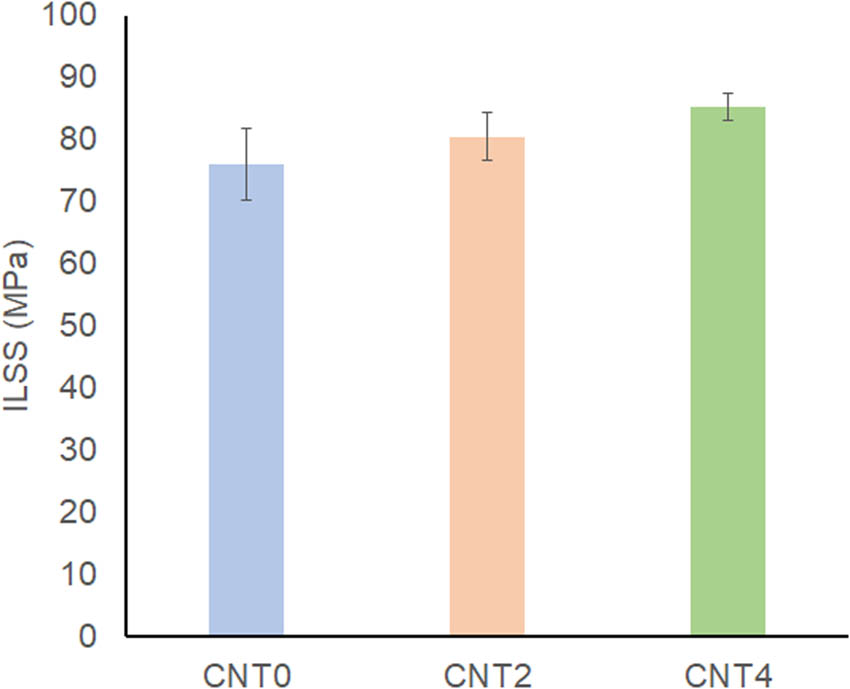
Influence of CNTs on the ILSS.
Finally, SEM was used to study the side surface of the impacted specimens to identify the type of damage and their locations on the sample. Figure 8(a) and (b) show a cross-section of a CNT0 sample, while Figure 9(a)–(c) present a cross-section of a CNT2 sample. The presence of delamination between the different plies is evident in the SEM image. The delamination lengths are significant and spread throughout the thickness of the composite.

SEM observations of a cross-section of a CNT0 sample after the SBS test in 2 mm (a) and 200 μm (b) scales.

SEM observations of a cross-section of a CNT2 sample after a SBS test in 2 mm (a), 1 mm (b), and 200 µm (c) scales.
In contrast, the delamination lengths at the end of the test are much reduced for the composite with CNTF interleaves. Even for the 2 CNTF composite, it can be seen that the addition of the CNT layer strengthens the interface. We can observe that the damage mode is different, and the presence of the robust interface at the CNT layer means that the damage is deflected to intralaminar damage.
3.2 Flexure properties of CFRP with and without CNTF
The flexural load–displacement curve (average measured three-point bending results from samples tested three times for each) of CNT0, CNT2, and CNT4 are given in Figure 10(a) and (b) for 0° and 90° specimens, respectively. A comparison of the slope within the elastic range of the flexural load–displacement curves of CNTF interleaved specimens (CNT2 and CNT4) with baseline CFRP (CNT0) specimens demonstrates that the addition of CNTF increases the longitudinal stiffness of interleaved specimens. The failure displacement of the 0° CFRP (CNT0) specimens showed that the load dropped after a displacement of 3.65 mm, while the failure displacements of the CNTs-CFRP specimens ranged no more than 3.5 mm. It indicates that the addition of CNTF has increased the stiffness but decreased the elongation of the 0° specimens. Among the three types of samples, the CNT4 specimens had the highest load-carrying capacity, while the control group CNT0 had the lowest peak loading. In the unloading process, all the specimens showed fluctuating curves, reflecting that the specimens have experienced damage initiation, load re-distribution, damage propagation, and fracture and failure. In Figure 10(b), the flexural load–displacement curve of the transverse specimen shows that CNTs-CFRP specimens have higher yield load compared to CFRP specimens, and the loading displacement of the CNT0 specimens was smaller than that of the CNT2 and CNT4 specimens. It may be because the load-bearing capacity of 90° specimens mainly depends on the epoxy matrix. The insertion of CNTF can increase the toughness of the resin matrix and delay the damage initiation and propagation.

Average flexural load – displacement curve of (a) 0° specimens and (b) 90° specimens for three types of specimens (CNT0, CNT2, and CNT4).
SEM microscopic image (Figure 11) of the fractured surface of interleaved specimens shows the adhesion of CNTF, epoxy resin, and carbon fiber. As can be seen, the CNTF has adhered to the epoxy resin, and it can provide bridging and prevent the crack development of the matrix.

SEM micrographs of the combination of CNTs with fiber and matrix in CNT-FRP.
After the flexural load–displacement curves were obtained, the flexural strength and modulus could be calculated following the calculation formula of ASTM D7264. The calculated flexural strength and modulus results are shown in Table 2 below.
Average flexural modulus, strength, and failure displacement of specimens
| Group |
|
∆ (%) |
|
∆ (%) |
|
∆ (%) |
|
|---|---|---|---|---|---|---|---|
| CNT0-0° | 1132.3 | — | 94.7 | — | 3.87 | — | 16.98 |
| CNT2-0° | 1215.4 | 7.33 | 98.3 | 3.79 | 3.83 | −1.03 | 16.89 |
| CNT4-0° | 1288.2 | 13.76 | 108.28 | 14.34 | 3.56 | −8.01 | 2.42 |
| CNT0-90° | 72.21 | — | 8.82 | — | 1.71 | — | 4.93 |
| CNT2-90° | 82.76 | 14.61 | 8.31 | −6.14 | 2.19 | 28.07 | 3.81 |
| CNT4-90° | 89.58 | 24.05 | 8.61 | −2.44 | 2.37 | 38.60 | 9.32 |
3.3 Results of low velocity impact
In order to study the mechanism of impact damage, the front and rear surfaces of samples were observed by optical microscope. Figure 12 shows the apparent morphology of the impact surface (the upper part in the red box) and the rear (the lower part in the red box) of three samples after impact, respectively. Under the 5 J impact energy, different degrees of dents appeared on the surface of the samples, and the impact damage in the samples mainly included fiber fracture, debonding, and matrix cracking.

Close-up view of front and back impact specimens. (a) CNT0-0°, (b) CNT2-0°, (c) CNT4-0°.
First, the fracture cracks along the width caused by the impact were studied using the in-plane CT scan of the specimens (Figure 13). For the fracture cracks of the CNT0 specimen propagated all through the width of the specimen (as shown in Figure 13(a)). The transverse crack length on the surface of CNT4 specimens was short, and the fiber fracture on the back was not apparent. In the internal view from the CT scan (as shown in Figure 13(c)), the transverse damage crack expansion only accounted for about 1/2 of the total width of the specimens and did not extend to the end. In contrast, the CNT2 specimens exhibited more severe cracks than the CNT4 specimens. A transverse fiber fracture crack in CNT2 specimens had extended to the one edge of the specimen, and the fiber fracture on the back was much more noticeable. Meanwhile, along the fiber direction, the specimens are split with long cracks due to the weak strength dominated by the matrix in the direction perpendicular to the fiber in the 0° specimens.

Analysis of fiber fracture extension length: the cutting position is in the middle of the specimens: (a) CNT0-0°; (b) CNT2-0°; and (c) CNT4-0°.
In order to further understand the internal damage after impact, the difference between the impacted samples with and without CNTF was analyzed using CT to scan the thickness direction of the specimens, as shown in Figure 14. For all the specimens, the cracks and delamination could be observed. The damage of CNT0-0° was mainly fiber buckling and fiber breakage close to the back side of the impacted specimen, as well as delamination between the FRP layers. For the CNTs-CFRP specimens, fiber breakage and delamination exist, but the damage is less concentrated and less severe than in CNT0 specimens. Meanwhile, the overall deformation for specimens with CNTs films was less noticeable than the CNT0 specimen, showing that the specimens with CNTFs are reinforced and less deformed than the CNT0 specimens. However, in CNTs-CFRP specimens, the delamination are located near the insertion of CNTF and have propagated for a long distance, and this becomes the primary way of impact energy dissipation for CNTs-CFRP specimens. It may be because the adhesion between CNTF and carbon fiber prepreg layers was not as perfect as that between CFRP prepreg layers.

CT scan of damage from the cross section: (a) CNT0-0°; (b) CNT2-0°; and (c) CNT4-0°.
Finally, the internal crack development of the specimens was analyzed by calculating the pore volume using VGSTUDIO MAX software. Table 3 lists the volume of the scanned specimen segment (V s), the volume of the pore part in the scanned segment (V ps), the porosity ratio of the specimens (e ps), and the increased ratio after adding CNTF (∆ CNT0). The volume of the damaged part is colored in the 3D diagram in Figure 15, with the color bar showing from blue, green to red, for the increase in damage severity. Before adding CNTF, the CFRP specimen was dominated by red, while for the CNT4 sample, the color was mainly green and blue. It indicates that the reinforced sample with CNTF could delay the crack evolution and effectively prevent excessive crack development. This is due to the fact that CNTF can absorb more energy when the reinforced specimen is subjected to load. Ultimately, the delamination failure and damage propagation are mostly concentrated near the CNTF layer rather than the CFRP fiber fracture. In comparison, the pores generated in CFRP specimens are not only caused by damage in the fiber direction, but also caused by fiber breakage. According to the comparison in Table 3, it was observed that the porosity of CNTs-CFRP specimens was less than CNT0 specimen, with a decrease of 1.26 and 20.59% for CNT2 and CNT4, respectively, indicating that the CNTF added in CFRP specimens can help to resist the damage propagation.
Comparison of pore volume and porosity of different specimens
| Specimen | V s (mm3) | ∆ CNT0 (%) | V ps (mm3) | ∆ CNT0 (%) | e ps (%) | ∆ CNT0 (%) |
|---|---|---|---|---|---|---|
| CNT0-0° | 1032.7 | — | 30.16 | — | 2.838 | — |
| CNT2-0° | 1066.2 | 3.25 | 29.78 | −1.26 | 2.718 | −4.23 |
| CNT4-0° | 1109.0 | 7.39 | 23.95 | −20.59 | 2.114 | −25.51 |

Overall 3D pore analysis view of different samples: (a) CNT0-0°; (b) CNT2-0°; and (c) CNT4-0°.
3.4 FAI properties of CFRP with and without CNTF
Figure 16 shows the load–displacement curves of the three types of specimens during 3-point bending test after impact. Generally, the FAI load–displacement curve was similar to the flexural load–displacement curve before impact. However, it can be seen that compared with Figure 10, the maximum flexural load value has decreased due to impact damage. The FAI load of the CNT4 specimens was remarkably higher than the CNT0 specimens, indicating less impact damage in the interleaved specimen. Meanwhile, it can also be seen that the deformation of the CNT0 specimen is more severe than that of the reinforced specimen with CNTF, the same as that in the flexural testing on the specimens before impact. Another observation from the curves was that the displacement value of interleaved specimens when reaching the ultimate load in FAI was smaller than CNT0 specimens.

Average FAI load–displacement curve of 0° specimens (CNT0, CNT2, and CNT4).
The bending and residual bending values of CFRP laminates before and after impact are obtained and listed in Table 4.
Flexural properties of specimens before and after impact
| Sample ID | Flexural modulus: E (GPa) | Flexural strength:
|
Failure load: F (N) | ||||||
|---|---|---|---|---|---|---|---|---|---|
| E ud | E d | −∆ (%) |
|
|
−∆ (%) | F ud | F d | −∆ (%) | |
| CNT0-0° | 94.70 | 24.59 | 74.03 | 1132.3 | 572.96 | 49.40 | 842.69 | 426.40 | 49.40 |
| CNT2-0° | 98.30 | 17.94 | 81.74 | 1215.4 | 507.20 | 58.27 | 1001.9 | 418.10 | 58.27 |
| CNT4-0° | 108.28 | 16.37 | 84.88 | 1288.2 | 526.53 | 59.13 | 1115.4 | 455.93 | 59.13 |
The flexural properties of CNT0 specimens are better after impact, and the reduction ratio was smaller than that of the reinforced specimens by CNTF. However, the overall flexural properties of the reinforced specimens were improved even though the reduction ratio was larger after impact load. The bending property of reinforced specimens decreases significantly after being subjected to impact load, but its overall bending property was improved. With the insertion of CNTF from 2 to 4 layers, the bending modulus of the reinforced sample decreased more than the bending strength, indicating that the modulus was more sensitive to impact damage.
From the CT scan shown in Figure 17, the CNT0 specimen is observed to have apparent delamination failure at the central impact position. Further observation revealed that on the impact position of the CNT0 specimen on the back side, the protrusion caused by fiber fracture is more prominent, indicating that irreversible damage has occurred in the specimen and led to decreased material stiffness. However, the CNT4-0° specimens displayed minor delamination damage in the CT scan of the through-thickness cross-section and minor fiber fracture on the back side of the impacted specimen. It was attributed to the enhancement of the interaction between the fiber and the matrix system by CNTF, promoting the whole system to absorb more energy.

The view of CT scans through thickness: CNT0-0°, CNT4-0°-S1, and CNT4-0°-S2.
The fracture surface of CFRP laminate structure was uneven after failure in the FAI, as shown in Figure 18. From the SEM images of the CFRP specimen, the fiber bundles were broken in the fracture by the external force, and fibers were pulled out, or the matrix has been destroyed, and fibers are exposed from the matrix. From the enlarged figure in Figure 18(b), the carbon fibers have a very smooth surface without matrix adhered, indicating that the bonding between fiber and matrix was relatively low.

Fracture surface of CFRP beams with different magnifications: (a) 50 μm and (b) 20 μm.
For specimens with CNTF, as shown in Figure 19, the surface of the carbon fiber bundle was also smooth due to debonding with the resin. However, the CNTF have adhered to the epoxy resin (penetrated to some extent) and the surface of carbon fibers. In contrast, the resin around the carbon fiber bundles had been separated from the bundles with noticeable gaps. Compared with CNT0 specimens, the CNTF can bring binding effects into the CFRP laminates and improve the material properties. The binding effects can be summarized in the following aspects:
Penetration and bridging between CNTs and matrix.
Adhesion between CNTF and carbon fiber surface.
The pull-out of CNTs from a matrix or debonding from the matrix and carbon fiber increases the energy absorption.

Microscopy image of fracture of CNTF-CFRP beams: (a) 10 μm and (b) 2 μm.
It could be observed from Figure 19(a) that the upper CNTF had partially smooth bonding surfaces, which suggests that the bonding effect of the preparation process could be improved.
4 Conclusion
This work experimentally studied the effect of CNTF introduced in carbon fiber composites as interleaves on the flexural response. Three composites were studied; baseline carbon epoxy composite without any CNTF, composite with 2 CNTFs, and composite with 4 CNTFs. The flexural response of the composites was studied using SBS, three-point bending, and FAI conditions. The key outcomes of the study are as follows:
The CNTF positively affects the ILSS found from the SBS test. The improvement in ILSS was of the order of 10%, which is similar to that published in the literature on composites modified by CNT [49].
For 0° unidirectional (UD) specimens, the maximum bending strength and bending modulus of CNTs-CFRP specimens have increased by 14.34 and 13.76% after the insertion of 4 layers of CNTF. However, the displacement of failure of 0° UD specimens has decreased. The bending modulus and failure displacement of 90° UD specimens has increased by 24.05 and 38.60%, while the bending strength of CNTs-CFRP specimens decreased.
The CT scanning results reveal that the impact damage evolution in the UD 0° CNTs-CFRP specimens was less than that of CFRP specimens. The internal failure of the CNTs-CFRP specimens was mainly delamination, while that of CFRP specimens was mainly fiber breakage. Furthermore, the porosity analysis of the specimens confirmed that the CNTs-CFRP specimens have lower porosity than the CFRP specimen, for instance, the average pore volume of CNT4 specimens decreased by 20.59%.
The bending property of CNTs-CFRP specimens was better than CFRP specimens before impact. However, the flexural property of CNT-CFRP specimens after impact was lower than that of the CFRP specimens. Compared to the flexural strength, the flexural modulus of CNTs-CFRP specimens decreased more after impact, indicating that the flexural modulus was more sensitive to impact damage.
The microscopic, SEM, and CT scanning analysis showed that the CNTF adhered firmly to both the matrix and the carbon fiber of the CFRP laminates. CNTF can enhance the strength and modulus of the CFRP and plays a significant role in dissipating load energy. Therefore, CNTF can be applied to the surface of the composite material, forming a protective layer that absorbs energy from impacts.
Overall, using CNTF in composites shows promise to improve the impact damage resistance of CFRP laminates and to increase the potential applications of CNTF in various industries. However, further research is still needed to fully understand the effects of CNTs on composite materials and optimize their use.
-
Funding information: The research has been supported by the Natural Science Foundation of Guangdong Province, China (Grant No. 2022A1515011433), 111 Project (Grant No. D21021), Municipal Science and Technology Planning Project of Guangzhou (Grant No. 20212200004), and Key Discipline of Materials Science and Engineering, Bureau of Education of Guangzhou (Grant No. 202255464).
-
Author contributions: All authors have accepted responsibility for the entire content of this manuscript and approved its submission.
-
Conflict of interest: David Hui, who is the co-author of this article, is a current Editorial Board member of Nanotechnology Reviews. This fact did not affect the peer-review process. The authors declare no other conflict of interest.
-
Data availability statement: The raw/processed data required to reproduce these findings can be shared upon request.
References
[1] Nebe M, Schmack T, Schaefer T, Walther F. Experimental and numerical investigation on the impact response of CFRP under 3-point-bending. Compos Part C: Open Access. 2021;4:100079.10.1016/j.jcomc.2020.100079Search in Google Scholar
[2] Lin Y, Min J, Teng H, Lin J, Hu J, Xu N. Flexural performance of steel-FRP composites for automotive applications. Automot Innov. 2020;3(3):280–95.10.1007/s42154-020-00109-xSearch in Google Scholar
[3] Wu W, Liu Q, Zong Z, Sun G, Li Q. Experimental investigation into transverse crashworthiness of CFRP adhesively bonded joints in vehicle structure. Compos Struct. 2013;106:581–9.10.1016/j.compstruct.2013.07.009Search in Google Scholar
[4] Shrivastava R, Singh KK. Interlaminar Fracture Toughness Characterization of Laminated Composites: A Review. Polym Rev. 2020;60(3):542–93.10.1080/15583724.2019.1677708Search in Google Scholar
[5] Domun N, Kaboglu C, Paton KR, Dear JP, Liu J, Blackman BRK, et al. Ballistic impact behaviour of glass fibre reinforced polymer composite with 1D/2D nanomodified epoxy matrices. Compos Part B: Eng. 2019;167:497–506.10.1016/j.compositesb.2019.03.024Search in Google Scholar
[6] Tong L, Mouritz A, Bannister MK. 3D fibre reinforced polymer composites. Oxford, UK: Elsevier; 2002.10.1016/B978-008043938-9/50017-XSearch in Google Scholar
[7] Mouritz AP. Review of z-pinned composite laminates. Compos Part A: Appl Sci Manuf. 2007;38(12):2383–97.10.1016/j.compositesa.2007.08.016Search in Google Scholar
[8] Ahmadi-Moghadam B, Sharafimasooleh M, Shadlou S, Taheri F. Effect of functionalization of graphene nanoplatelets on the mechanical response of graphene/epoxy composites. Mater Des (1980–2015). 2015;66:142–9.10.1016/j.matdes.2014.10.047Search in Google Scholar
[9] Carolan D, Ivankovic A, Kinloch AJ, Sprenger S, Taylor AC. Toughened carbon fibre-reinforced polymer composites with nanoparticle-modified epoxy matrices. J Mater Sci. 2017;52(3):1767–88.10.1007/s10853-016-0468-5Search in Google Scholar
[10] Shin YC, Lee WI, Kim HS. Mode II interlaminar fracture toughness of carbon nanotubes/epoxy film-interleaved carbon fiber composites. Compos Struct. 2020;236:111808.10.1016/j.compstruct.2019.111808Search in Google Scholar
[11] Bilisik K, Erdogan G, Sapanci E, Gungor S. Mode-II toughness of nanostitched carbon/epoxy multiwall carbon nanotubes prepreg composites: Experimental investigation by using end notched flexure. J Compos Mater. 2019;53(28–30):4249–71.10.1177/0021998319857462Search in Google Scholar
[12] Srivastava AK, Gupta V, Yerramalli CS, Singh A. Flexural strength enhancement in carbon-fiber epoxy composites through graphene nano-platelets coating on fibers. Compos Part B: Eng. 2019;179:107539.10.1016/j.compositesb.2019.107539Search in Google Scholar
[13] Ning H, Li J, Hu N, Yan C, Liu Y, Wu L, et al. Interlaminar mechanical properties of carbon fiber reinforced plastic laminates modified with graphene oxide interleaf. Carbon. 2015;91:224–33.10.1016/j.carbon.2015.04.054Search in Google Scholar
[14] Qu S, Jiang X, Li Q, Gao L, Zhou G, Zhang D, et al. Developing strong and tough carbon nanotube films by a proper dispersing strategy and enhanced interfacial interactions. Carbon. 2019;149:117–24.10.1016/j.carbon.2019.04.033Search in Google Scholar
[15] Yu Y, Shi Y, Kurita H, Jia Y, Wang Z, Narita F. Carbon fiber-reinforced piezoelectric nanocomposites: Design, fabrication and evaluation for damage detection and energy harvesting. Compos Part A: Appl Sci Manuf. 2023;172:107587.10.1016/j.compositesa.2023.107587Search in Google Scholar
[16] Fakhreddini-Najafabadi S, Torabi M, Taheri-Behrooz F. An experimental investigation on the low-velocity impact performance of the CFRP filled with nanoclay. Aerosp Sci Technol. 2021;116:106858.10.1016/j.ast.2021.106858Search in Google Scholar
[17] Xin W, Sarasini F, Tirillò J, Bavasso I, Sbardella F, Lampani L, et al. Impact and post-impact properties of multiscale carbon fiber composites interleaved with carbon nanotube sheets. Compos Part B: Eng. 2020;183:107711.10.1016/j.compositesb.2019.107711Search in Google Scholar
[18] Gilbert EN, Hayes BS, Seferis JC. Interlayer toughened unidirectional carbon prepreg systems: effect of preformed particle morphology. Compos Part A: Appl Sci Manuf. 2003;34(3):245–52.10.1016/S1359-835X(02)00141-0Search in Google Scholar
[19] Teng X, Xu Y, Zhang W, Liu W. The use of pre-hole Z-pinning (PHZ) method to improve the impact resistance and post-impact flexural performance of composite skin/stringer joints. Thin-Walled Struct. 2022;180:109909.10.1016/j.tws.2022.109909Search in Google Scholar
[20] Fan Y, Li M, Gu Y, Wang S, Wang Y. Effects of Z-pin on moisture absorption property and damage mode under flexural load for carbon fiber composite. Sci Eng Compos Mater. 2022;29(1):206–14.10.1515/secm-2022-0020Search in Google Scholar
[21] İnal O, Katnam KB, Potluri P, Soutis C. Progress in interlaminar toughening of aerospace polymer composites using particles and non-woven veils. Aeronaut J. 2022;126(1295):222–48.10.1017/aer.2021.95Search in Google Scholar
[22] Ou Y, González C, Vilatela JJ. Interlaminar toughening in structural carbon fiber/epoxy composites interleaved with carbon nanotube veils. Compos Part A Appl Sci Manuf. 2019;124:105477.10.1016/j.compositesa.2019.105477Search in Google Scholar
[23] Sathishkumar S, Jawahar P, Chakraborti P. Influence of carbonaceous reinforcements on mechanical and tribological properties of PEEK composites - a review. Polym Technol Mater. 2022;61(12):1367–84.10.1080/25740881.2022.2061995Search in Google Scholar
[24] Mittal G, Rhee KY, Mišković-Stanković V, Hui D. Reinforcements in multi-scale polymer composites: Processing, properties, and applications. Compos Part B Eng. 2018;138:122–39.10.1016/j.compositesb.2017.11.028Search in Google Scholar
[25] Al-Maharma AY, Sendur P. Review of the main factors controlling the fracture toughness and impact strength properties of natural composites. Mater Res Express. 2019;6(2):022001.10.1088/2053-1591/aaec28Search in Google Scholar
[26] Pandey JK, Ahn SH, Lee CS, Mohanty AK, Misra M. Recent advances in the application of natural fiber based composites. Macromol Mater Eng. 2010;295(11):975–89.10.1002/mame.201000095Search in Google Scholar
[27] Bilisik K, Syduzzaman M. Carbon nanotubes in carbon/epoxy multiscale textile preform composites: A review. Polym Compos. 2021;42(4):1670–97.10.1002/pc.25955Search in Google Scholar
[28] Wang M, Li N, Wang GD, Lu SW, Zhao QD, Liu XL. High-sensitive flexural sensors for health monitoring of composite materials using embedded carbon nanotube (CNT) buckypaper. Compos Struct. 2021;261:113280.10.1016/j.compstruct.2020.113280Search in Google Scholar
[29] Li J, Zhang Z, Fu J, Liang Z, Ramakrishnan KR. Mechanical properties and structural health monitoring performance of carbon nanotube-modified FRP composites: A review. Nanotechnol Rev. 2021;10(1):1438–68.10.1515/ntrev-2021-0104Search in Google Scholar
[30] Zhang C, Zhang G, Shi X, Wang X. Effects of carbon nanotubes on the interlaminar shear strength and fracture toughness of carbon fiber composite laminates: A review. J Mater Sci. 2022;57(4):2388–410.10.1007/s10853-021-06734-zSearch in Google Scholar
[31] Al-Maharma AY, Sendur P, Al-Huniti N. Critical review of the factors dominating the fracture toughness of CNT reinforced polymer composites. Mater Res Express. 2019;6(1):012003.10.1088/2053-1591/aae867Search in Google Scholar
[32] Rawat P, Singh KK. An impact behavior analysis of CNT-based fiber reinforced composites validated by LS-DYNA: A review. Polym Compos. 2017;38(1):175–84.10.1002/pc.23573Search in Google Scholar
[33] Zakaria MR, Akil HM, Omar MF, Abdullah MMAB, Rahman AAA, Othman MBH. Improving flexural and dielectric properties of carbon fiber epoxy composite laminates reinforced with carbon nanotubes interlayer using electrospray deposition. Nanotechnol Rev. 2020;9(1):1170–82.10.1515/ntrev-2020-0090Search in Google Scholar
[34] Jen YM, Ni WL. Effect of dispersing multiwalled carbon nanotubes and graphene nanoplatelets hybrids in the matrix on the flexural fatigue properties of carbon/epoxy composites. Polymers. 2022;14(5):918.10.3390/polym14050918Search in Google Scholar PubMed PubMed Central
[35] Yang G, Cheng F, Zuo S, Zhang J, Xu Y, Hu Y, et al. Growing carbon nanotubes in situ surrounding carbon fiber surface via chemical vapor deposition to reinforce flexural strength of carbon fiber composites. Polymers. 2023;15(10):2309.10.3390/polym15102309Search in Google Scholar PubMed PubMed Central
[36] Taş H, Soykok IF. Effects of carbon nanotube inclusion into the carbon fiber reinforced laminated composites on flexural stiffness: A numerical and theoretical study. Compos Part B Eng. 2019;159:44–52.10.1016/j.compositesb.2018.09.055Search in Google Scholar
[37] Zhouyi Li, Zhenbiao Hu, Haokang Wang, Tao Suo. Mechanical properties of CFRP composites with CNT film interlayer under different strain rates. Chin J High Press Phys. 2019;33(2):125–33.10.1007/JHEP06(2019)125Search in Google Scholar
[38] Sánchez M, Campo M, Jiménez-Suárez A, Ureña A. Effect of the carbon nanotube functionalization on flexural properties of multiscale carbon fiber/epoxy composites manufactured by VARIM. Compos Part B Eng. 2013;45(1):1613–9.10.1016/j.compositesb.2012.09.063Search in Google Scholar
[39] Shin Y, Kim S. Enhancement of the interlaminar fracture toughness of a carbon-fiber-reinforced polymer using interleaved carbon nanotube buckypaper. Appl Sci. 2021;11(15):6821.10.3390/app11156821Search in Google Scholar
[40] Cheng X, Liu L, Feng X, Shen L, Wu Z. Low temperature-based flexural properties of carbon fiber/epoxy composite laminates incorporated with carbon nanotube sheets. Macromol Mater Eng. 2019;304(10):1900247.10.1002/mame.201900247Search in Google Scholar
[41] Ou Y, González C, Vilatela JJ. Understanding interlaminar toughening of unidirectional CFRP laminates with carbon nanotube veils. Compos Part B Eng. 2020;201:108372.10.1016/j.compositesb.2020.108372Search in Google Scholar
[42] Koirala P, van de Werken N, Lu H, Baughman RH, Ovalle-Robles R, Tehrani M. Using ultra-thin interlaminar carbon nanotube sheets to enhance the mechanical and electrical properties of carbon fiber reinforced polymer composites. Compos Part B Eng. 2021;216:108842.10.1016/j.compositesb.2021.108842Search in Google Scholar
[43] Hart KR, Chia PXL, Sheridan LE, Wetzel ED, Sottos NR, White SR. Comparison of compression-after-impact and flexure-after-impact protocols for 2D and 3D woven fiber-reinforced composites. Compos Part A Appl Sci Manuf. 2017;101:471–9.10.1016/j.compositesa.2017.07.005Search in Google Scholar
[44] Yuan B, Ye M, Hu Y, Cheng F, Hu X. Flexure and flexure-after-impact properties of carbon fibre composites interleaved with ultra-thin non-woven aramid fibre veils. Compos Part A Appl Sci Manuf. 2020;131:105813.10.1016/j.compositesa.2020.105813Search in Google Scholar
[45] Xu X, Zhou Z, Hei Y, Zhang B, Bao J, Chen X. Improving compression-after-impact performance of carbon–fiber composites by CNTs/thermoplastic hybrid film interlayer. Compos Sci Technol. 2014;95:75–81.10.1016/j.compscitech.2014.01.023Search in Google Scholar
[46] Yuan B, Tan B, Hu Y, Shaw J, Hu X. Improving impact resistance and residual compressive strength of carbon fibre composites using un-bonded non-woven short aramid fibre veil. Compos Part A: Appl Sci Manuf. 2019;121:439–48.10.1016/j.compositesa.2019.04.006Search in Google Scholar
[47] Pascoe J, Pimenta S, Pinho ST. Interlocking thin-ply reinforcement concept for improved fracture toughness and damage tolerance. Compos Sci Technol. 2019;181:107681.10.1016/j.compscitech.2019.107681Search in Google Scholar
[48] Greene JP. Physical and mechanical properties. In: Greene JP, editor. Automotive plastics and composites. Norwich, NY: William Andrew Publishing; 2021. p. 39–55.10.1016/B978-0-12-818008-2.00012-XSearch in Google Scholar
[49] Bilisik K, Karaduman N, Sapanci E. Short-beam shear of nanoprepreg/nanostitched three-dimensional carbon/epoxy multiwall carbon nanotube composites. J Compos Mater. 2019;54(3):311–29.10.1177/0021998319863472Search in Google Scholar
[50] De Cicco D, Asaee Z, Taheri F. Use of nanoparticles for enhancing the interlaminar properties of fiber-reinforced composites and adhesively bonded joints—A review. Nanomaterials. 2017;7(11):360.10.3390/nano7110360Search in Google Scholar PubMed PubMed Central
© 2023 the author(s), published by De Gruyter
This work is licensed under the Creative Commons Attribution 4.0 International License.
Articles in the same Issue
- Research Articles
- Preparation of CdS–Ag2S nanocomposites by ultrasound-assisted UV photolysis treatment and its visible light photocatalysis activity
- Significance of nanoparticle radius and inter-particle spacing toward the radiative water-based alumina nanofluid flow over a rotating disk
- Aptamer-based detection of serotonin based on the rapid in situ synthesis of colorimetric gold nanoparticles
- Investigation of the nucleation and growth behavior of Ti2AlC and Ti3AlC nano-precipitates in TiAl alloys
- Dynamic recrystallization behavior and nucleation mechanism of dual-scale SiCp/A356 composites processed by P/M method
- High mechanical performance of 3-aminopropyl triethoxy silane/epoxy cured in a sandwich construction of 3D carbon felts foam and woven basalt fibers
- Applying solution of spray polyurea elastomer in asphalt binder: Feasibility analysis and DSR study based on the MSCR and LAS tests
- Study on the chronic toxicity and carcinogenicity of iron-based bioabsorbable stents
- Influence of microalloying with B on the microstructure and properties of brazed joints with Ag–Cu–Zn–Sn filler metal
- Thermohydraulic performance of thermal system integrated with twisted turbulator inserts using ternary hybrid nanofluids
- Study of mechanical properties of epoxy/graphene and epoxy/halloysite nanocomposites
- Effects of CaO addition on the CuW composite containing micro- and nano-sized tungsten particles synthesized via aluminothermic coupling with silicothermic reduction
- Cu and Al2O3-based hybrid nanofluid flow through a porous cavity
- Design of functional vancomycin-embedded bio-derived extracellular matrix hydrogels for repairing infectious bone defects
- Study on nanocrystalline coating prepared by electro-spraying 316L metal wire and its corrosion performance
- Axial compression performance of CFST columns reinforced by ultra-high-performance nano-concrete under long-term loading
- Tungsten trioxide nanocomposite for conventional soliton and noise-like pulse generation in anomalous dispersion laser cavity
- Microstructure and electrical contact behavior of the nano-yttria-modified Cu-Al2O3/30Mo/3SiC composite
- Melting rheology in thermally stratified graphene-mineral oil reservoir (third-grade nanofluid) with slip condition
- Re-examination of nonlinear vibration and nonlinear bending of porous sandwich cylindrical panels reinforced by graphene platelets
- Parametric simulation of hybrid nanofluid flow consisting of cobalt ferrite nanoparticles with second-order slip and variable viscosity over an extending surface
- Chitosan-capped silver nanoparticles with potent and selective intrinsic activity against the breast cancer cells
- Multi-core/shell SiO2@Al2O3 nanostructures deposited on Ti3AlC2 to enhance high-temperature stability and microwave absorption properties
- Solution-processed Bi2S3/BiVO4/TiO2 ternary heterojunction photoanode with enhanced photoelectrochemical performance
- Electroporation effect of ZnO nanoarrays under low voltage for water disinfection
- NIR-II window absorbing graphene oxide-coated gold nanorods and graphene quantum dot-coupled gold nanorods for photothermal cancer therapy
- Nonlinear three-dimensional stability characteristics of geometrically imperfect nanoshells under axial compression and surface residual stress
- Investigation of different nanoparticles properties on the thermal conductivity and viscosity of nanofluids by molecular dynamics simulation
- Optimized Cu2O-{100} facet for generation of different reactive oxidative species via peroxymonosulfate activation at specific pH values to efficient acetaminophen removal
- Brownian and thermal diffusivity impact due to the Maxwell nanofluid (graphene/engine oil) flow with motile microorganisms and Joule heating
- Appraising the dielectric properties and the effectiveness of electromagnetic shielding of graphene reinforced silicone rubber nanocomposite
- Synthesis of Ag and Cu nanoparticles by plasma discharge in inorganic salt solutions
- Low-cost and large-scale preparation of ultrafine TiO2@C hybrids for high-performance degradation of methyl orange and formaldehyde under visible light
- Utilization of waste glass with natural pozzolan in the production of self-glazed glass-ceramic materials
- Mechanical performance of date palm fiber-reinforced concrete modified with nano-activated carbon
- Melting point of dried gold nanoparticles prepared with ultrasonic spray pyrolysis and lyophilisation
- Graphene nanofibers: A modern approach towards tailored gypsum composites
- Role of localized magnetic field in vortex generation in tri-hybrid nanofluid flow: A numerical approach
- Intelligent computing for the double-diffusive peristaltic rheology of magneto couple stress nanomaterials
- Bioconvection transport of upper convected Maxwell nanoliquid with gyrotactic microorganism, nonlinear thermal radiation, and chemical reaction
- 3D printing of porous Ti6Al4V bone tissue engineering scaffold and surface anodization preparation of nanotubes to enhance its biological property
- Bioinspired ferromagnetic CoFe2O4 nanoparticles: Potential pharmaceutical and medical applications
- Significance of gyrotactic microorganisms on the MHD tangent hyperbolic nanofluid flow across an elastic slender surface: Numerical analysis
- Performance of polycarboxylate superplasticisers in seawater-blended cement: Effect from chemical structure and nano modification
- Entropy minimization of GO–Ag/KO cross-hybrid nanofluid over a convectively heated surface
- Oxygen plasma assisted room temperature bonding for manufacturing SU-8 polymer micro/nanoscale nozzle
- Performance and mechanism of CO2 reduction by DBD-coupled mesoporous SiO2
- Polyarylene ether nitrile dielectric films modified by HNTs@PDA hybrids for high-temperature resistant organic electronics field
- Exploration of generalized two-phase free convection magnetohydrodynamic flow of dusty tetra-hybrid Casson nanofluid between parallel microplates
- Hygrothermal bending analysis of sandwich nanoplates with FG porous core and piezomagnetic faces via nonlocal strain gradient theory
- Design and optimization of a TiO2/RGO-supported epoxy multilayer microwave absorber by the modified local best particle swarm optimization algorithm
- Mechanical properties and frost resistance of recycled brick aggregate concrete modified by nano-SiO2
- Self-template synthesis of hollow flower-like NiCo2O4 nanoparticles as an efficient bifunctional catalyst for oxygen reduction and oxygen evolution in alkaline media
- High-performance wearable flexible strain sensors based on an AgNWs/rGO/TPU electrospun nanofiber film for monitoring human activities
- High-performance lithium–selenium batteries enabled by nitrogen-doped porous carbon from peanut meal
- Investigating effects of Lorentz forces and convective heating on ternary hybrid nanofluid flow over a curved surface using homotopy analysis method
- Exploring the potential of biogenic magnesium oxide nanoparticles for cytotoxicity: In vitro and in silico studies on HCT116 and HT29 cells and DPPH radical scavenging
- Enhanced visible-light-driven photocatalytic degradation of azo dyes by heteroatom-doped nickel tungstate nanoparticles
- A facile method to synthesize nZVI-doped polypyrrole-based carbon nanotube for Ag(i) removal
- Improved osseointegration of dental titanium implants by TiO2 nanotube arrays with self-assembled recombinant IGF-1 in type 2 diabetes mellitus rat model
- Functionalized SWCNTs@Ag–TiO2 nanocomposites induce ROS-mediated apoptosis and autophagy in liver cancer cells
- Triboelectric nanogenerator based on a water droplet spring with a concave spherical surface for harvesting wave energy and detecting pressure
- A mathematical approach for modeling the blood flow containing nanoparticles by employing the Buongiorno’s model
- Molecular dynamics study on dynamic interlayer friction of graphene and its strain effect
- Induction of apoptosis and autophagy via regulation of AKT and JNK mitogen-activated protein kinase pathways in breast cancer cell lines exposed to gold nanoparticles loaded with TNF-α and combined with doxorubicin
- Effect of PVA fibers on durability of nano-SiO2-reinforced cement-based composites subjected to wet-thermal and chloride salt-coupled environment
- Effect of polyvinyl alcohol fibers on mechanical properties of nano-SiO2-reinforced geopolymer composites under a complex environment
- In vitro studies of titanium dioxide nanoparticles modified with glutathione as a potential drug delivery system
- Comparative investigations of Ag/H2O nanofluid and Ag-CuO/H2O hybrid nanofluid with Darcy-Forchheimer flow over a curved surface
- Study on deformation characteristics of multi-pass continuous drawing of micro copper wire based on crystal plasticity finite element method
- Properties of ultra-high-performance self-compacting fiber-reinforced concrete modified with nanomaterials
- Prediction of lap shear strength of GNP and TiO2/epoxy nanocomposite adhesives
- A novel exploration of how localized magnetic field affects vortex generation of trihybrid nanofluids
- Fabrication and physicochemical characterization of copper oxide–pyrrhotite nanocomposites for the cytotoxic effects on HepG2 cells and the mechanism
- Thermal radiative flow of cross nanofluid due to a stretched cylinder containing microorganisms
- In vitro study of the biphasic calcium phosphate/chitosan hybrid biomaterial scaffold fabricated via solvent casting and evaporation technique for bone regeneration
- Insights into the thermal characteristics and dynamics of stagnant blood conveying titanium oxide, alumina, and silver nanoparticles subject to Lorentz force and internal heating over a curved surface
- Effects of nano-SiO2 additives on carbon fiber-reinforced fly ash–slag geopolymer composites performance: Workability, mechanical properties, and microstructure
- Energy bandgap and thermal characteristics of non-Darcian MHD rotating hybridity nanofluid thin film flow: Nanotechnology application
- Green synthesis and characterization of ginger-extract-based oxali-palladium nanoparticles for colorectal cancer: Downregulation of REG4 and apoptosis induction
- Abnormal evolution of resistivity and microstructure of annealed Ag nanoparticles/Ag–Mo films
- Preparation of water-based dextran-coated Fe3O4 magnetic fluid for magnetic hyperthermia
- Statistical investigations and morphological aspects of cross-rheological material suspended in transportation of alumina, silica, titanium, and ethylene glycol via the Galerkin algorithm
- Effect of CNT film interleaves on the flexural properties and strength after impact of CFRP composites
- Self-assembled nanoscale entities: Preparative process optimization, payload release, and enhanced bioavailability of thymoquinone natural product
- Structure–mechanical property relationships of 3D-printed porous polydimethylsiloxane films
- Nonlinear thermal radiation and the slip effect on a 3D bioconvection flow of the Casson nanofluid in a rotating frame via a homotopy analysis mechanism
- Residual mechanical properties of concrete incorporated with nano supplementary cementitious materials exposed to elevated temperature
- Time-independent three-dimensional flow of a water-based hybrid nanofluid past a Riga plate with slips and convective conditions: A homotopic solution
- Lightweight and high-strength polyarylene ether nitrile-based composites for efficient electromagnetic interference shielding
- Review Articles
- Recycling waste sources into nanocomposites of graphene materials: Overview from an energy-focused perspective
- Hybrid nanofiller reinforcement in thermoset and biothermoset applications: A review
- Current state-of-the-art review of nanotechnology-based therapeutics for viral pandemics: Special attention to COVID-19
- Solid lipid nanoparticles for targeted natural and synthetic drugs delivery in high-incidence cancers, and other diseases: Roles of preparation methods, lipid composition, transitional stability, and release profiles in nanocarriers’ development
- Critical review on experimental and theoretical studies of elastic properties of wurtzite-structured ZnO nanowires
- Polyurea micro-/nano-capsule applications in construction industry: A review
- A comprehensive review and clinical guide to molecular and serological diagnostic tests and future development: In vitro diagnostic testing for COVID-19
- Recent advances in electrocatalytic oxidation of 5-hydroxymethylfurfural to 2,5-furandicarboxylic acid: Mechanism, catalyst, coupling system
- Research progress and prospect of silica-based polymer nanofluids in enhanced oil recovery
- Review of the pharmacokinetics of nanodrugs
- Engineered nanoflowers, nanotrees, nanostars, nanodendrites, and nanoleaves for biomedical applications
- Research progress of biopolymers combined with stem cells in the repair of intrauterine adhesions
- Progress in FEM modeling on mechanical and electromechanical properties of carbon nanotube cement-based composites
- Antifouling induced by surface wettability of poly(dimethyl siloxane) and its nanocomposites
- TiO2 aerogel composite high-efficiency photocatalysts for environmental treatment and hydrogen energy production
- Structural properties of alumina surfaces and their roles in the synthesis of environmentally persistent free radicals (EPFRs)
- Nanoparticles for the potential treatment of Alzheimer’s disease: A physiopathological approach
- Current status of synthesis and consolidation strategies for thermo-resistant nanoalloys and their general applications
- Recent research progress on the stimuli-responsive smart membrane: A review
- Dispersion of carbon nanotubes in aqueous cementitious materials: A review
- Applications of DNA tetrahedron nanostructure in cancer diagnosis and anticancer drugs delivery
- Magnetic nanoparticles in 3D-printed scaffolds for biomedical applications
- An overview of the synthesis of silicon carbide–boron carbide composite powders
- Organolead halide perovskites: Synthetic routes, structural features, and their potential in the development of photovoltaic
- Recent advancements in nanotechnology application on wood and bamboo materials: A review
- Application of aptamer-functionalized nanomaterials in molecular imaging of tumors
- Recent progress on corrosion mechanisms of graphene-reinforced metal matrix composites
- Research progress on preparation, modification, and application of phenolic aerogel
- Application of nanomaterials in early diagnosis of cancer
- Plant mediated-green synthesis of zinc oxide nanoparticles: An insight into biomedical applications
- Recent developments in terahertz quantum cascade lasers for practical applications
- Recent progress in dielectric/metal/dielectric electrodes for foldable light-emitting devices
- Nanocoatings for ballistic applications: A review
- A mini-review on MoS2 membrane for water desalination: Recent development and challenges
- Recent updates in nanotechnological advances for wound healing: A narrative review
- Recent advances in DNA nanomaterials for cancer diagnosis and treatment
- Electrochemical micro- and nanobiosensors for in vivo reactive oxygen/nitrogen species measurement in the brain
- Advances in organic–inorganic nanocomposites for cancer imaging and therapy
- Advancements in aluminum matrix composites reinforced with carbides and graphene: A comprehensive review
- Modification effects of nanosilica on asphalt binders: A review
- Decellularized extracellular matrix as a promising biomaterial for musculoskeletal tissue regeneration
- Review of the sol–gel method in preparing nano TiO2 for advanced oxidation process
- Micro/nano manufacturing aircraft surface with anti-icing and deicing performances: An overview
- Cell type-targeting nanoparticles in treating central nervous system diseases: Challenges and hopes
- An overview of hydrogen production from Al-based materials
- A review of application, modification, and prospect of melamine foam
- A review of the performance of fibre-reinforced composite laminates with carbon nanotubes
- Research on AFM tip-related nanofabrication of two-dimensional materials
- Advances in phase change building materials: An overview
- Development of graphene and graphene quantum dots toward biomedical engineering applications: A review
- Nanoremediation approaches for the mitigation of heavy metal contamination in vegetables: An overview
- Photodynamic therapy empowered by nanotechnology for oral and dental science: Progress and perspectives
- Biosynthesis of metal nanoparticles: Bioreduction and biomineralization
- Current diagnostic and therapeutic approaches for severe acute respiratory syndrome coronavirus-2 (SARS-COV-2) and the role of nanomaterial-based theragnosis in combating the pandemic
- Application of two-dimensional black phosphorus material in wound healing
- Special Issue on Advanced Nanomaterials and Composites for Energy Conversion and Storage - Part I
- Helical fluorinated carbon nanotubes/iron(iii) fluoride hybrid with multilevel transportation channels and rich active sites for lithium/fluorinated carbon primary battery
- The progress of cathode materials in aqueous zinc-ion batteries
- Special Issue on Advanced Nanomaterials for Carbon Capture, Environment and Utilization for Energy Sustainability - Part I
- Effect of polypropylene fiber and nano-silica on the compressive strength and frost resistance of recycled brick aggregate concrete
- Mechanochemical design of nanomaterials for catalytic applications with a benign-by-design focus