Enhanced electrical conductivity and electromagnetic shielding properties of multi-component polymer/graphite nanocomposites prepared by solid-state shear milling
-
Jiliang Xie
 ,
Li Chen
,
Li Chen

Abstract
This study investigates a novel multi-component polymer composite method for preparing graphite/polymer composites with excellent electrical conductivity and electromagnetic shielding properties, aiming to address the challenges in achieving a balance between conductivity, mechanical stability, and thermal properties in applications like electronics, automotive, and aerospace. Expanded graphite (EG) was used as a conductive filler, and solid-state shear milling was employed to achieve uniform dispersion of graphite in a polymer matrix consisting of polyvinyl chloride (PVC), chlorinated polyethylene (CPE), and polyurethane elastomer (TPU), improving mechanical and thermal stability. X-ray diffraction, Raman spectroscopy, scanning electron microscopy, transmission electron microscopy, and conductivity tests revealed significant differences in graphite dispersion across substrates. In the EG/PVC-CPE system, graphite sheets are stripped into multiple layers, while in the EG/PVC-TPU system, they form thinner or even single layers, leading to enhanced conductivity and shielding efficiency. The results show that the EG/PVC-CPE and EG/PVC-TPU composites offer improved electrical and mechanical properties, demonstrating the potential of multi-component matrices and solid-state shear milling in developing high-performance composites for conductivity and electromagnetic interference shielding applications.
1 Introduction
Graphene has recently garnered significant attention due to its exceptional electrical, mechanical, thermal, and chemical properties, making it a focal point in the research of polymer matrix composites [1,2]. Its nanoscale thickness and unique two-dimensional layered structure offer immense potential for applications in electronics, energy storage, and sensors [3,4]. However, the strong van der Waals interactions between graphene sheets lead to poor dispersion in polymer matrices, hindering the full utilization of its outstanding physical properties [5,6]. Addressing this challenge has become a critical focus in the field of polymer composites.
Traditional methods, such as liquid-phase exfoliation and chemical vapor deposition, can produce few-layer graphene. However, these methods are often plagued by issues such as poor dispersion effects, low efficiency, and environmental concerns, which limit their practicality in large-scale production [7,8]. Recently, solid-state shear milling (S3M) has emerged as a promising technique for preparing graphene/polymer composites. This method effectively exfoliates graphite and achieves uniform dispersion under solvent-free and environmentally friendly conditions [9,10]. S3M utilizes a high-shear-force field to exfoliate graphite flakes within a polymer matrix, significantly enhancing the mechanical properties, electrical conductivity, and electromagnetic shielding performance of the composites [11,12].
In this study, S3M technology was employed to regulate the exfoliation and dispersion behavior of expanded graphite (EG) within polymer matrices such as polyvinyl chloride (PVC), chlorinated polyethylene (CPE), and polyurethane elastomer (TPU). The process utilized high-efficiency mixing equipment and a disk-type mechanochemical reactor to produce graphenized EG/polymer composite materials [13,14]. Characterization techniques, including X-ray diffraction (XRD), scanning electron microscopy (SEM), transmission electron microscopy (TEM), and Raman spectroscopy, were applied to analyze the microstructure and exfoliation behavior of the graphite sheets comprehensively. The primary objective was to maximize the exfoliation and dispersion of EG within the polymer matrix while simultaneously improving the mechanical and electrical properties of the composites.
Despite the advancements offered by S3M technology, achieving complete exfoliation and uniform dispersion with a single polymer matrix, such as PVC, remains challenging. Enhancements in the degree of exfoliation and dispersion can be achieved by incorporating viscosity modifiers or elastomers like CPE and TPU. This approach not only facilitates better dispersion of graphite sheets but also further improves the composite material’s electrical conductivity and electromagnetic shielding performance.
2 Experimental part
2.1 Reagents and instruments
PVC: SG-5, particle size 0.1–0.3 mm, Shaanxi Jintai Chlor-Alkali Chemical Co., Ltd. CPE: HG/T2704-2002 135A, Weifang Xingyuan Plastic Co., Ltd. TPU: Bayer385, Bayer Corporation. EG: KP250, Qingdao Nanshu Ruiying Graphite Co., Ltd [15]. Ethylenediamine bismaleimide complex lanthanum (III) heat stabilizer: homemade. Dioctyl phthalate (DOP): Analytically pure, Chengdu McCaxi Chemical Co., Ltd. Mill type force chemical reactor: MF-400 variable frequency type, Chengdu Pumeiyi Technology Co., Ltd.
2.2 Preparation process
The preparation route of the composite material is shown in Figure 1.
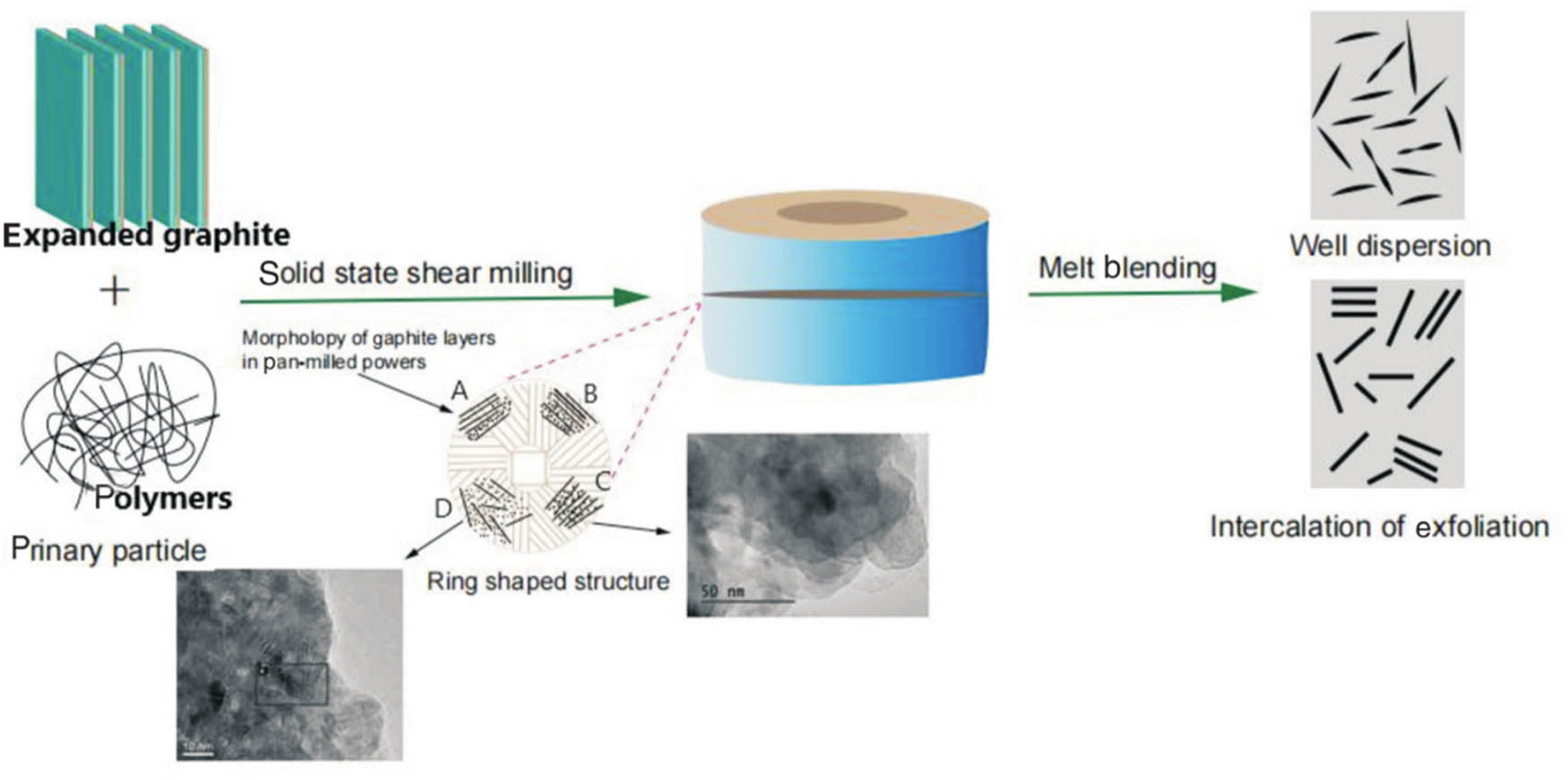
Dispersion and spalling of graphite in polymer matrix based on S3M.
Disc crusher stages A, B, C, and D show grinding, sliding, peeling, and dispersion. The disc crusher s ring structure is its primary component for generating strong shear forces. When the EG/PVC-TPE composite powder prepared by S3M is diluted by melting and mixing with PVC-TPE, graphene/PVC-TPE nanocomposites with good graphene dispersion can be prepared in PVC-TPE matrix [16].
2.2.1 Preparation of EG
The 2.0 g EG was evenly spread in 1,000 mL beaker, then put into a microwave reactor, and removed by 560 W irradiated expansion for 20 s to obtain EG.
2.2.2 Preparation of EG/PVC, EG/PVC/CPE, and EG/PVC/TPU composite powders
PVC and EG were combined at a specified mass ratio, with the addition of a 4% ethylenediamine bismaleimide-lanthanum (III) complex as a heat stabilizer. The mixture was initially blended in a high-speed mixer. Subsequently, it was introduced into a grinding disk-type mechanochemical reactor, where grinding was performed at room temperature. During the grinding process, circulating water was used for cooling, while the pressure was regulated using a spiral pressure device. The grinding speed was controlled by an adjustable motor and transmission system [17]. In this experiment, the grinding disk was operated at a speed of 30 rpm, producing EG/PVC composite powder.
Similarly, PVC, CPE, and EG were mixed in a specific ratio, and the resulting blend was processed to obtain EG/PVC-CPE composite powder following the same preparation method used for EG/PVC powder. Additionally, PVC, TPU, and EG were mixed in a defined proportion, and the EG/PVC-TPU composite powder was prepared using the same procedure as that for EG/PVC powder.
2.2.3 Preparation of EG/PVC, EG/PVC-CPE, and EG/PVC-TPU composites
The EG-PVC composite powder was mixed with a certain amount of PVC, 15% DOP and ethylenediamine bismaleimide combined lanthanum (III) complex heat stabilizer in a blender, and the resulting mixed powder was plasticized in a 90°C oven for 3 h. The plasticized powder was directly hot-pressed, and the forming condition was 12.5 MPa, 180°C, 10 min, to obtain EG/PVC composite material. EG/PVC-CPE and EG/PVC-TPU composites were prepared by EG/PVC-CPE and EG/PVC-TPU composite powders using the same process as above.
2.3 Examination and description
2.3.1 XRD analysis
The change in graphite layer spacing was determined by X‘PERT X-ray diffractometer of Philips Analytical Company with
Bragg equation is used to calculate the spacing between crystal faces
The Scherrer formula is used to calculate lattice parameters or microcrystal sizes
where
2.3.2 SEM analysis
The F-type SEM manufactured by the American FEI Company was utilized to observe the liquid nitrogen-fractured surfaces of composite materials or composite powders after gold sputtering treatment. This technique was used to analyze the morphology of the fractured sections or powders and to capture high-resolution images [18]. The observations were conducted under an acceleration voltage of 10 kV, ensuring optimal imaging quality.
Through SEM imaging, the morphological characteristics of the composite powders and cross-sections were analyzed in detail. The dispersion state of graphite within the polymer matrix was inferred based on the distribution and orientation of graphite sheets observed in the images. This analysis provided critical insights into the effectiveness of the S3M process in achieving uniform dispersion and exfoliation of graphite.
Moreover, SEM characterization enabled the identification of potential agglomeration or clustering of graphite sheets, which could impact the material’s electrical and mechanical properties. By correlating the morphological features with other experimental results, such as electrical conductivity and mechanical testing, a comprehensive understanding of the material’s structure–property relationship was established. This method is instrumental in optimizing the preparation process to enhance the performance of the composite materials.
2.3.3 TEM analysis
Ultrathin slices of EG/PVC and EG/PVC/CPE composites were made with Leica EMFC6 microslicing machine, and sheets of about 70 nm thick were made, or EG-PVC and EG-PVC CPE composite powders were directly attached to copper mesh, and examined using an H-600 TEM, taking pictures. It has a 75 kV acceleration voltage. The dispersion and peeling state of graphite in the composite system and the nanocomposite structure of the composite were characterized.
2.3.4 Atomic force microscope (AFM) analysis
The analysis was carried out with Innova AFM produced by Veeco, USA. The resolution was <0.2 µm and the standard 10× objective lens was observed (50× objective lens < µm). Sample preparation: The composite powder was dispersed in N-methylpyrrolidone (NMP) (0.1 g composite powder/100 mL NMP), and the ultrasonic power was 600 W for 10 min. The composite powder was coated on the silicon wafer for observation and analysis.
2.3.5 Laser Raman analysis
InVia laser Raman spectrometer, with
2.3.6 Laser particle size analysis
With a beam length of 2.50 mm and a pump speed of 2,400 rpm, the Mastersizer laser particle size analyzer manufactured by Malvern Instruments Co., Ltd was used to investigate the particle size distribution of EG-PVC composite powder.
2.3.7 Conductivity test
At room temperature, the sample resistivity was measured with ZC46A high resistance meter produced by Shanghai Precision Scientific Instrument Co., Ltd. The measuring voltage was 50 V and the measuring range was 106–1,014 Ω. The resistance of the composite material is less than 106 Ω. Use a multimeter to detect the composite material (the sample length × width × thickness is 10 cm × 1 cm × 0.1 cm).
2.3.8 Electromagnetic shielding performance analysis
The PNA-N5244A vector network analyzer from Agilent Technologies was employed to measure the S-scattering parameters of the composite materials, which were subsequently used to calculate the electromagnetic interference (EMI) shielding effectiveness (EMI SE). The testing was conducted using a coaxial approach to ensure precision and reliability in the measurements.
The test frequency range spanned from 2 to 18 GHz, covering a wide spectrum of electromagnetic waves relevant to practical applications. Samples were prepared in the form of coaxial rings with precise dimensions: an outer diameter of 7 mm, an inner diameter of 3 mm, and a thickness of 1 mm. These dimensions were chosen to fit the standard testing setup, ensuring consistency and comparability with other studies.
The coaxial measurement method allowed for accurate evaluation of the shielding performance by minimizing edge effects and ensuring uniform electromagnetic wave propagation through the samples. The obtained S-parameters (S11 and S21) provided detailed insights into the reflection, absorption, and transmission characteristics of the composite materials, enabling a comprehensive analysis of their electromagnetic shielding properties.
Additionally, the results from the vector network analyzer were used to validate the dispersion and exfoliation of graphite in the polymer matrix, as improved dispersion is directly correlated with enhanced electromagnetic shielding efficiency. This approach highlights the composite’s potential for applications in electronics, telecommunications, and aerospace, where effective EMI shielding is critical.
2.3.9 Mechanical properties test
Instron5507 universal material testing machine was used to test the tensile properties of the samples according to GB/T 1040, and the tensile speed was 10 mm/min.
3 Findings and discussion
3.1 Preparation of EG
Figure 2 shows the SEM photo of EG prepared by microwave irradiation expansion. It shows that EG is composed of many bonded and superimposed graphite scales. Under the action of expansion, the specific surface area of EG increases, there are many honeycomb microvoids between the lamella, the lamellar structure remains, the interlamellar distance increases, and the lamella becomes thinner.
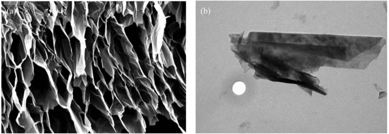
SEM images of EG prepared by (a) high-temperature expansion and (b) microwave-irradiation expansion.
Table 1 shows that EG prepared by microwave irradiation KP250 has the characteristics of high specific surface area, high volume expansion rate, and small pore volume, and average pore size, which proves that microwave irradiation is a better way to prepare EG.
Properties of EG prepared by microwave irradiation
| Expanding process | Expansion volume/(mL g−1) | Specific area/(m2 g−1) | Pore volume/(cm3 g−1) | Mean pore size/(nm) |
|---|---|---|---|---|
| Microwave irradiation in 560 W for 20 s | 288 | 61.747 | 0.16 | 83.5 |
3.2 Solid phase shear graphenization of EG
In the solid-phase co-milling of EG-PVC, the lamellar stripping of graphite and the formation of nanocomposites with PVC were achieved using a grinding disk-type mechanochemical reactor, which creates a strong shear force field. However, XRD, TEM, and Raman spectroscopy demonstrated that after 100 milling cycles, the graphite sheets in the EG-PVC system were still above five layers thick, indicating that complete graphenization of the EG was not achieved. This was primarily due to the insufficient viscosity of the polymer matrix [19].
To improve the viscosity of the polymer and facilitate better dispersion of graphite, CPE elastomer was added to the EG-PVC system. XRD, TEM, and Raman analysis of the CPE-EG-PVC system, after 40 milling cycles, revealed that the thickness of the graphite sheets was reduced to 3–4 nm. Considering the measured single-layer graphene thickness of 0.4–0.7 nm, the graphite sheets were approximately five layers thick, indicating that the material had reached a graphene-like structure. To further enhance the dispersion and exfoliation, CPE was substituted with the commercially available Bayer 385 TPU. When TPU-EG-PVC was milled for 40 rounds, the thickness of the graphite sheets was reduced to 1–4 nm, with the graphene sheets being approximately 1–5 layers thick.
Figure 3 shows the XRD patterns of EG-PVC (mass ratio 10/90), CPE-EG-PVC, and TPU-EG-PVC (mass ratio 10/10/80) composite powders after 40 milling cycles, while Table 2 presents the changes in key XRD parameters. From EG-PVC to CPE-EG-PVC to TPU-EG-PVC, the diffraction angle of the graphite phase increases, and the interlayer spacing (d-spacing) decreases. The XRD analysis also shows that the composite system with CPE exhibits the highest diffraction intensity and the largest half-peak width, indicating the most extensive exfoliation and peeling of the graphite sheets. In contrast, the TPU-EG-PVC system exhibits the lowest diffraction intensity, suggesting a further reduction in the thickness of the graphene lamellae.
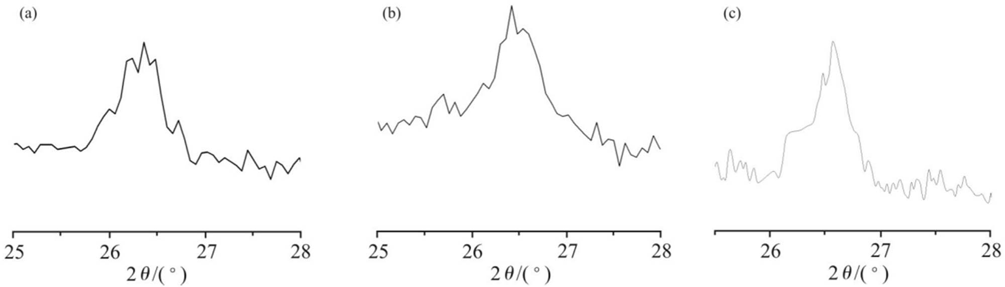
XRD patterns of different composite powders. (a) EG-PVC; (b) CPE-EG-PVC; (c) TPU-EG-PVC.
XRD parameters of cobalt powder
| Composite system |
|
D (002)/(nm) | Peak height | Peak full width at half maximum |
|---|---|---|---|---|
| EG-PVC | 26.35 | 0.339 | 200 | 0.65 |
| CPE-EG-PVC | 26.44 | 0.338 | 181 | 1.19 |
| TPU-EG-PVC | 26.55 | 0.333 | 125 | 0.66 |
These results demonstrate that the addition of CPE and TPU significantly improves the exfoliation and dispersion of EG in the polymer matrix. The reduction in the stacking thickness of the graphite sheets enhances the material’s potential for high electrical conductivity and electromagnetic shielding properties, making the modified composites more suitable for advanced applications.
Figure 4 shows the Raman spectra of
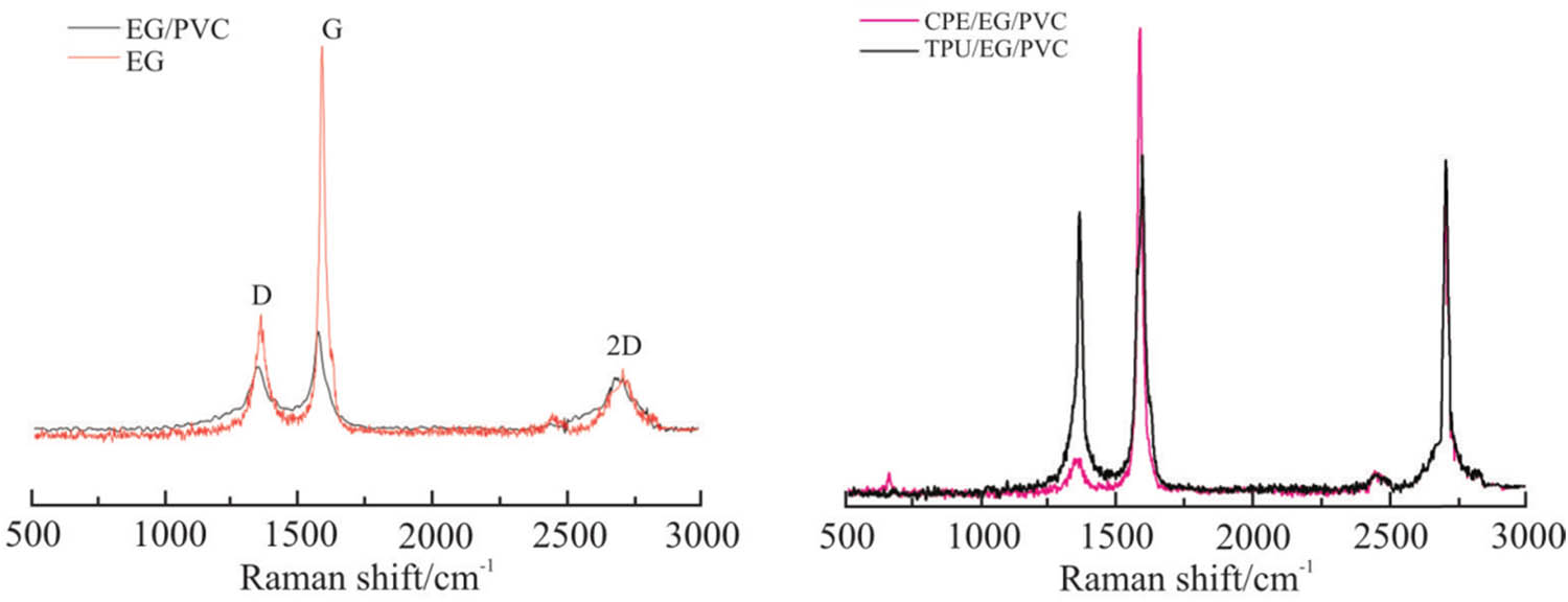
Raman spectra of EG and EG-PVC, CPE/EG/PVC, and TPU-EG-PVC.
Figure 5 presents the TEM images of the EG-PVC composite powder obtained after 40 milling cycles, with the black areas representing the graphite sheets. Figure 5(a) shows a view perpendicular to the graphene benzene ring structure, where the disordered striped morphology and the intercalation of PVC and graphite are clearly visible. Figure 5(b) displays a local magnification of image (a), offering a closer look at the graphite lamellae. It is evident that the graphite sheets are thinner and interlaced, with a thickness of approximately 10 nm, which aligns with the XRD analysis results. Figure 5(c) illustrates a parallel plane view of the graphene benzene rings, where large thin graphite sheets are stacked on top of each other, indicating that the graphite has undergone partial exfoliation. However, some regions still contain thicker lamellae, likely because not all EG was subjected to the same number of grinding cycles. This uneven milling could be due to variations in the grinding process, where some composite powder may have received less milling due to machine-related factors.
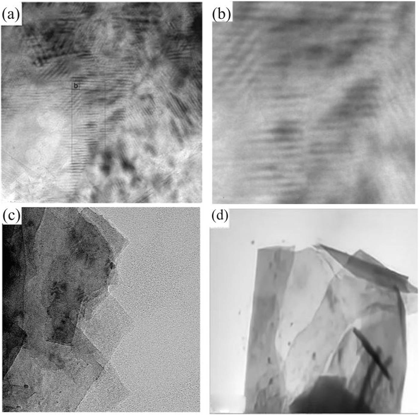
TEM photograph of GP40. (a) Longitudinal surface; (b) a partial enlarged view; (c) horizontal plane; (d) GP40 was ultrasonically dispersed in non-negative matrix factorization (NMF) and then dripped onto copper mesh for observation.
Figure 5(d) presents the TEM image of the composite powder after ultrasonic dispersion in a solvent. In this image, the graphite sheets’ large surface area and curled edges are clearly visible, further confirming the exfoliation and dispersion of the graphite in the polymer matrix. The dispersion method enhances the uniformity of the graphite sheets in the composite, contributing to improved properties such as electrical conductivity and mechanical strength.
These TEM observations provide valuable insight into the structural characteristics of the EG-PVC composites, highlighting the effects of grinding and ultrasonic dispersion on the exfoliation and dispersion of graphite within the polymer matrix. The reduced thickness of the graphite sheets and the successful exfoliation are key factors in enhancing the material’s performance in various applications.
Figure 6 is the TEM photo of the EG-PVC-CPE composite powder obtained by grinding 40 times, in which the black part is the graphite layer. Figure 6(c) shows the vertical graphene benzene torus field of view, in which the disordered striped structure and the mutual embedding of PVC and graphite can be seen. Figure 6(d) shows the local amplification of (c), which more intuitively shows the graphite lamellar thinning and interlacing with each other. The lamellar thickness is about 1 nm, that is, the thickness of two layers of graphene. In the vertical graphene-benzene torus observed in Figure 6(a), EG has been stripped, as seen by the huge, thin layers of graphene sheets that are visible. The composite powder’s TEM image following dissolving by ultrasonic is shown in Figure 6(b). The illustration shows the size of the graphite sheet and the curled edge.
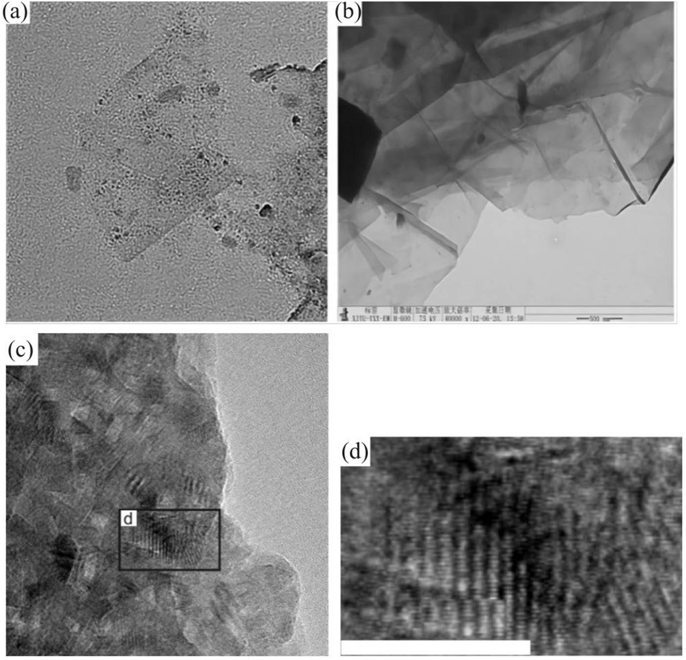
TEM image of graphene composite powder with 40% content (composite) powder. (a) Horizontal plane; (b) GCP40 was ultrasonically dispersed in NMF and then dropped onto copper mesh for observation; (c) longitudinal surfaces; (d) a partial enlarged view of (c).
In summary, through EG/PVC co-milling, and then the co-milling of EG/PVC-CPE, the graphene of EG is realized, and the thickness of the sheet is about five layers, reaching the level of graphene-like; Furthermore, EG/PVC-TPU co-milling achieves the graphenization of EG in polymer matrix and the nanocomposite with polymer (as shown in Figure 7). It is evident that TPE is essential for EG’s graphenization. Through the weak interlayer contact between the viscoelasticity of the polymer and EG, TPE modifies the viscoelasticity of the polymer and depends on the strong three-dimensional shear force field supplied by the mill-type mechanochemical reactor. In the co-milling of EG-TPE-PVC, the process of interface friction, tensile deformation dislocation, extrusion Mosaic, tensile slip, shear stripping and grinding, mixing, and dispersion (as shown in Figure 8), the continuous stripping of EG and graphene were realized, providing a new way for the preparation of graphene/polymer nanocomposites.
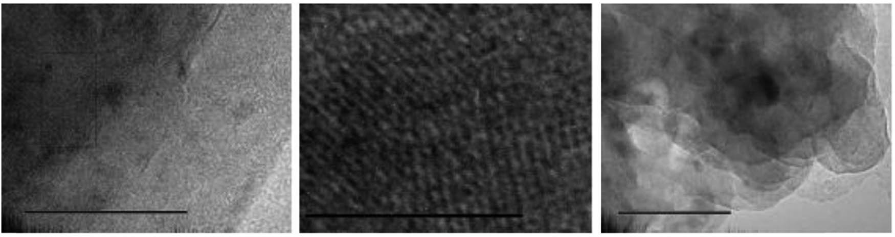
TEM image of EG-TPU-PVC composite powder.
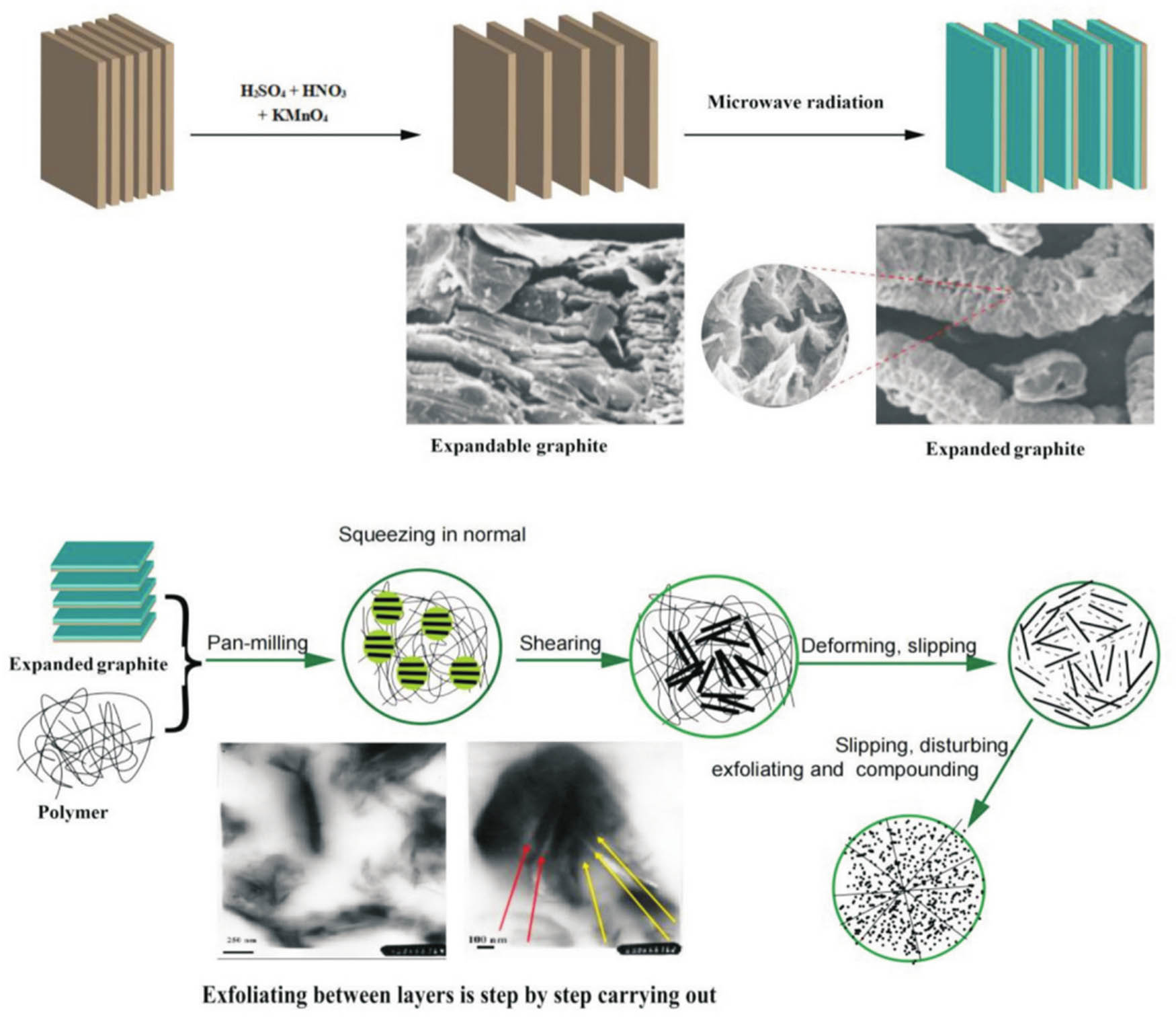
Graphitization process of graphite.
3.3 Structure and properties of graphene/elastomeric PVC nanocomposites
3.3.1 Structural morphology of graphene/elastomeric PVC nanocomposites
Figure 9 shows the SEM and TEM images of GE/CPE-PVC composites with 5% EG mass fraction. The SEM images show that the composite material maintains the morphology of the graphene fold lamellae at the macro level, and the graphene sheets are dispersed and embedded in the CPE-PVC matrix. TEM images of ultrathin slices of composite material show that the graphene sheets are evenly dispersed in the CPE PVC matrix, and the graphene sheets are bonded to each other to form conductive paths.
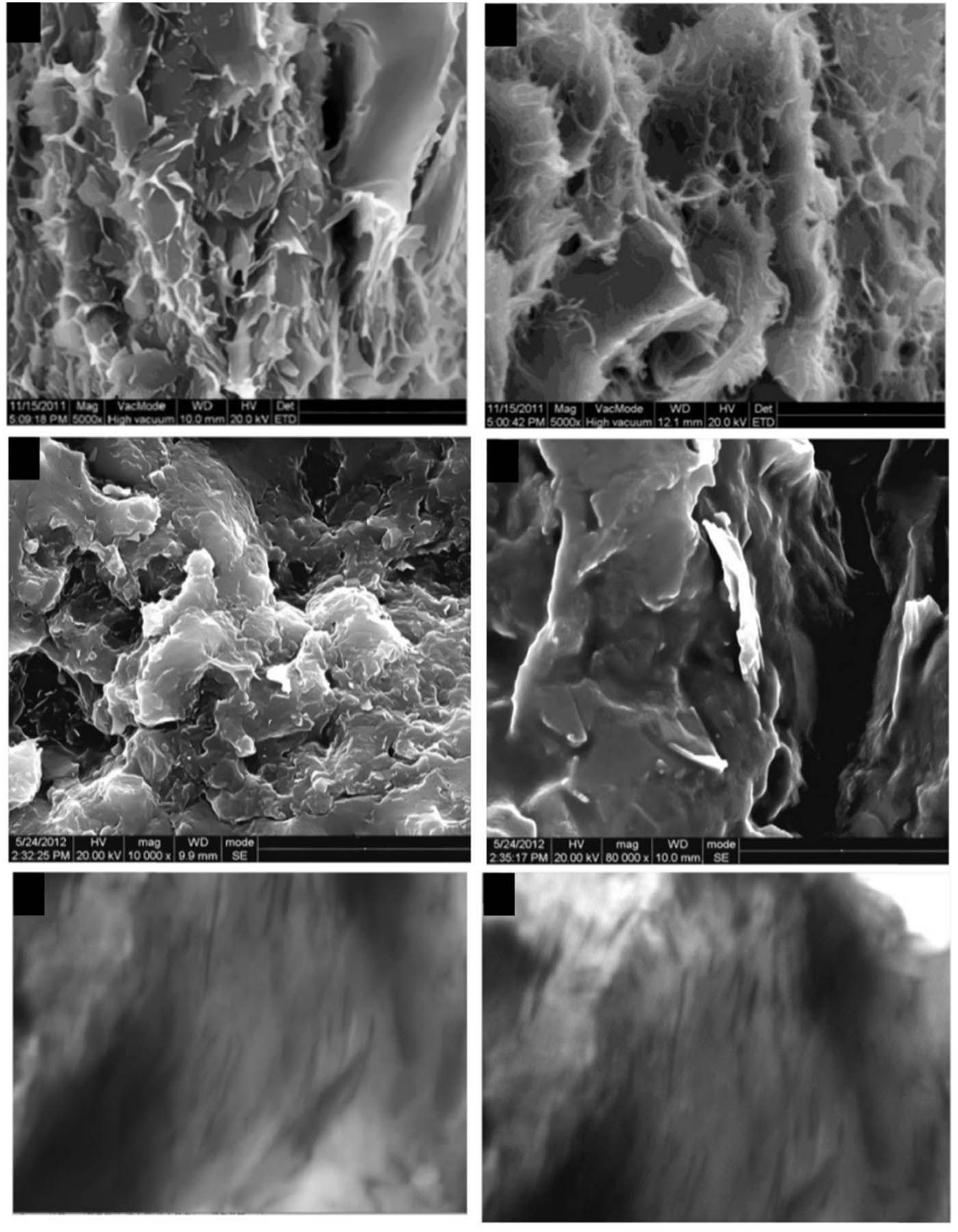
SEM and TEM images of graphene/PVC/CPE composites.
3.3.2 Electrical conductivity of graphene/elastomeric PVC nanocomposites
Here is the revised content with a more logical narrative sequence.
Figure 10 illustrates the relationship between the EG mass fraction and the volume conductivity of composite materials. Generally, the conductivity of the composite material increases with the EG content, demonstrating the formation of conductive networks as EG is incorporated. At a 3% EG mass fraction, the conductivity rises sharply by eight orders of magnitude, indicating the onset of conductive percolation where graphene sheets connect to form initial conductive pathways.
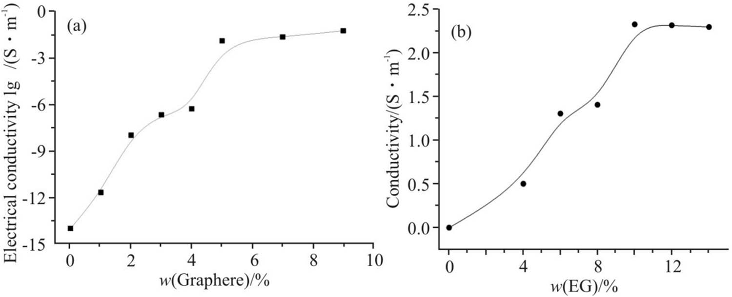
The effect of EG mass percentage on the graphene/elastomer PVC composites’ conductivity. (a) Graphene/CPE-PVC composites; (b) graphene/TPU-PVC composites.
Between 3 and 4% EG mass fraction, the conductivity shows minimal variation, likely due to the stabilization of the network structure. However, when the EG mass fraction exceeds 4%, a second percolation phenomenon occurs, leading to another sharp increase in conductivity. At a 5% EG mass fraction, the composite exhibits good antistatic performance and achieves a conductivity of 0.22 S/m.
Comparing different systems, the electrical conductivity of graphene/CPE-PVC composites is significantly enhanced compared to graphite/PVC nanocomposites. Furthermore, for the EG/TPU-PVC composite at a 5% EG mass fraction, the conductivity reaches 0.56 S/m. This improvement can be attributed to thinner graphite sheets, a higher degree of graphenization, and the formation of a more comprehensive conductive network as graphene sheets bond more effectively in the EG/PVC, EG/CPE-PVC, and EG/TPU-PVC systems, respectively.
3.3.3 Other properties of graphene/elastomeric PVC nanocomposites
Table 3 lists the electrical conductivity, thermal conductivity, electromagnetic shielding efficiency, and tensile strength of the graphene/elastomeric PVC composite.
Properties of graphene/elastomeric PVC composites
| Composite system (mass fraction, heat stabilizer 4%) | Electrical conductivity/(S m−1) | Thermal conductivity/(W m−1 K−1) |
|
Tensile strength/(MPa) | |
|---|---|---|---|---|---|
| PVC |
|
0.180 ± 0.006 | 3.00 ± 0.11 | 7.16 ± 0.23 | 20.34 ± 1.04 |
| EG/PVC (5/91) | (4.2 ± 0.14) × 10−2 | 0.366 ± 0.013 | 23.73 ± 0.70 | 41.73 ± 1.26 | 27.94 ± 1.42 |
| EG/CPE-PVC (5/10/81) | 0.20 ± 0.02 | 0.464 ± 0.012 | 26.41 ± 0.77 | 44.88 ± 1.33 | 22.32 ± 1.10 |
| EG/TPU-PVC (5/10/81) | 0.57 ± 0.03 | 1.200 ± 0.034 | 28.00 ± 0.82 | 47.00 ± 1.43 | 25.30 ± 1.25 |
Upon achieving a mass fraction of 5% in EG, the electrical conductivity, thermal conductivity and electromagnetic shielding efficiency of the nanocomposites from EG/PVC, EG/CPE-PVC to EG/TPU-PVC system increase successively. The results indicated that the graphene/elastomeric PVC nanocomposites were successfully prepared by the gradual graphenization of graphite in the grinding disk co-milling.
4 Conclusion
In this study, a novel multi-component polymer/graphite composite material was successfully prepared, with graphite effectively exfoliated and uniformly dispersed using the S3M method. By adjusting the combinations of PVC, CPE, and TPU, the distribution of graphite within the matrix was optimized, resulting in significantly improved conductivity and electromagnetic shielding efficiency. The results indicate that the electrical properties of the EG/PVC-CPE and EG/PVC-TPU systems are influenced by variations in the degree of graphite exfoliation and uniformity, which directly impact the electrical conductivity and electromagnetic shielding properties of the composites. In the EG/PVC-TPU system, the presence of single or even multiple layers of exfoliated graphite leads to higher electrical conductivity and excellent electromagnetic shielding performance. Additionally, the composite exhibits good mechanical strength and thermal stability, suggesting that this composite system holds great potential for practical applications, particularly in the development of EMI protection for electronic devices and high-conductivity materials.
The findings of this study offer new insights into the design and application of high-performance polymer/graphite composites. They further confirm the effectiveness of multi-component systems and the solid-state shear grinding method in optimizing composite properties, particularly in terms of electromagnetic shielding and electrical conductivity. Future research could explore additional filler and matrix combinations to further enhance the overall properties of composite materials and provide more reliable material solutions for advanced applications.
-
Funding information: Authors state no funding involved.
-
Author contributions: Conceptualization: Jiliang Xie and Li Chen; methodology: Yanxia Zeng; software: Jiliang Xie; validation: Jiliang Xie, Yanxia Zeng, and Xin Xiao; formal analysis: Xin Xiao; investigation: Xia Sun; resources: Li Chen; data curation: Xin Xiao; writing – original draft preparation: Jiliang Xie; writing – review and editing: Yanxia Zeng; visualization: Yanxia Zeng; supervision: Xin Xiao; project administration: Xia Sun; funding acquisition: Xia Sun. All authors have accepted responsibility for the entire content of this manuscript and approved its submission.
-
Conflict of interest: Authors state no conflict of interest.
-
Data availability statement: All data generated or analyzed during this study are included in this published article.
References
[1] Cheng H, Zhang G, Liu X, Lin Y, Ma S, Lin G, et al. Achieving acceptable electromagnetic interference shielding in UHMWPE/ground tire rubber composites by building a segregated network of hybrid conductive carbon black. Nanocomposites. 2023;9(1):100–15.10.1080/20550324.2023.2251202Suche in Google Scholar
[2] Zhang Y, Xu J, Zhang Z, Zhao L, Li M, Li M, et al. Mechanochemical synthesis of nanostructured and composite oxide ceramics: From mechanisms to tailored properties. Int J Appl Ceram Technol. 2024;21(2):616–54.10.1111/ijac.14598Suche in Google Scholar
[3] Liao Y, Tan Q, Yang S, Chen Y, Chen G, Bai S. High value recycle of waste cross-linking polyethylene with the contribution of phosphogypsum to prepare composites. Waste Biomass Valoriz. 2023;14(11):3909–21.10.1007/s12649-023-02065-zSuche in Google Scholar
[4] Zeng Y. A review of the research progress of composite bipolar plates for proton exchange membrane fuel cells with different substrate materials. Adv Eng Technol Res. 2023;8(1):517.10.56028/aetr.8.1.517.2023Suche in Google Scholar
[5] Patti A, Acierno D. Structure‐property relationships of waterborne polyurethane (WPU) in aqueous formulations. J Vinyl Addit Technol. 2023;29(4):589–606.10.1002/vnl.21981Suche in Google Scholar
[6] Wang P, Liao Q, Zhang H. Polysaccharide-based double-network hydrogels: Polysaccharide effect, strengthening mechanisms, and applications. Biomacromolecules. 2023;24(12):5479–510.10.1021/acs.biomac.3c00765Suche in Google Scholar PubMed
[7] Elmi C. Physical-chemical properties of nano-sized phyllosilicates: recent environmental and industrial advancements. Encyclopedia. 2023;3(4):1439–60.10.3390/encyclopedia3040103Suche in Google Scholar
[8] Zhang Y, Wu H, Zhang W, Yang F. Polymer nanocomposites based on nano magnesium hydroxide. Chem Phys Polym Nanocompos: Process Morphol Struct Thermodyn Rheol. 2024;2:423–69.10.1002/9783527837021.ch14Suche in Google Scholar
[9] Yanga Y, Hua C, Liub Q, Lia J. Research progress and prospects of colored zirconia ceramics: A review. J Adv Ceram. 2024;13(10):1505–22.10.26599/JAC.2024.9220941Suche in Google Scholar
[10] Boldyreva E. Spiers memorial lecture: Mechanochemistry, tribochemistry, mechanical alloying–retrospect, achievements and challenges. Faraday Discuss. 2023;241:9–62.10.1039/D2FD00149GSuche in Google Scholar
[11] Chen Y, Li J, Li T, Zhang L, Meng F. Recent advances in graphene-based films for electromagnetic interference shielding: Review and future prospects. Carbon. 2021;180:163–84.10.1016/j.carbon.2021.04.091Suche in Google Scholar
[12] Verma S, Dhangar M, Mili M, Bajpai H, Dwivedi U, Kumari N, et al. Review on engineering designing of electromagnetic interference shielding materials using additive manufacturing. Polym Compos. 2022;43(7):4081–99.10.1002/pc.26684Suche in Google Scholar
[13] Liang X, Xu Y, Lin YE, Zhang C. Federated split learning via dynamic aggregation and homomorphic encryption on non-IID data. J Supercomput. 2025;81(1):63.10.1007/s11227-024-06612-wSuche in Google Scholar
[14] Zahid M, Siddique S, Anum R, Shakir MF, Nawab Y, Rehan ZA. M-type barium hexaferrite-based nanocomposites for EMI shielding application: A review. J Supercond Nov Magn. 2022;34:1019–45.10.1007/s10948-021-05859-1Suche in Google Scholar
[15] Gezahegn S, Garcia C, Lai R, Zhou X, Tjong J, Thomas SC, et al. Benign species-tuned biomass carbonization to nano-layered graphite for EMI filtering and greener energy storage functions. Renew Energy. 2021;164:1039–51.10.1016/j.renene.2020.10.010Suche in Google Scholar
[16] Sanghvi MR, Tambare OH, More AP. Performance of various fillers in adhesives applications: A review. Polym Bull. 2021;79(12):10491–553.10.1007/s00289-021-04022-zSuche in Google Scholar
[17] Duan Y, Gao M, Pang H, Wang T. FeCoNiMnAl high-entropy alloy: Improving electromagnetic wave absorption properties. J Mater Res. 2022;36(10):2107–17.10.1557/s43578-021-00242-1Suche in Google Scholar
[18] Jagadeeshanayaka N, Awasthi S, Jambagi SC, Srivastava C. Bioactive surface modifications through thermally sprayed hydroxyapatite composite coatings: A review of selective reinforcements. Biomater Sci. 2022;10(10):2484–523.10.1039/D2BM00039CSuche in Google Scholar PubMed
[19] Valencia L, Handa R, Monti S, Jasso-Salcedo AB, Georgouvelas D, Magaña I, et al. On the mineralization of nanocellulose to produce functional hybrid materials. J Mater Chem A. 2022;10(17):9248–76.10.1039/D2TA00457GSuche in Google Scholar
© 2025 the author(s), published by De Gruyter
This work is licensed under the Creative Commons Attribution 4.0 International License.
Artikel in diesem Heft
- Research Articles
- Generalized (ψ,φ)-contraction to investigate Volterra integral inclusions and fractal fractional PDEs in super-metric space with numerical experiments
- Solitons in ultrasound imaging: Exploring applications and enhancements via the Westervelt equation
- Stochastic improved Simpson for solving nonlinear fractional-order systems using product integration rules
- Exploring dynamical features like bifurcation assessment, sensitivity visualization, and solitary wave solutions of the integrable Akbota equation
- Research on surface defect detection method and optimization of paper-plastic composite bag based on improved combined segmentation algorithm
- Impact the sulphur content in Iraqi crude oil on the mechanical properties and corrosion behaviour of carbon steel in various types of API 5L pipelines and ASTM 106 grade B
- Unravelling quiescent optical solitons: An exploration of the complex Ginzburg–Landau equation with nonlinear chromatic dispersion and self-phase modulation
- Perturbation-iteration approach for fractional-order logistic differential equations
- Variational formulations for the Euler and Navier–Stokes systems in fluid mechanics and related models
- Rotor response to unbalanced load and system performance considering variable bearing profile
- DeepFowl: Disease prediction from chicken excreta images using deep learning
- Channel flow of Ellis fluid due to cilia motion
- A case study of fractional-order varicella virus model to nonlinear dynamics strategy for control and prevalence
- Multi-point estimation weldment recognition and estimation of pose with data-driven robotics design
- Analysis of Hall current and nonuniform heating effects on magneto-convection between vertically aligned plates under the influence of electric and magnetic fields
- A comparative study on residual power series method and differential transform method through the time-fractional telegraph equation
- Insights from the nonlinear Schrödinger–Hirota equation with chromatic dispersion: Dynamics in fiber–optic communication
- Mathematical analysis of Jeffrey ferrofluid on stretching surface with the Darcy–Forchheimer model
- Exploring the interaction between lump, stripe and double-stripe, and periodic wave solutions of the Konopelchenko–Dubrovsky–Kaup–Kupershmidt system
- Computational investigation of tuberculosis and HIV/AIDS co-infection in fuzzy environment
- Signature verification by geometry and image processing
- Theoretical and numerical approach for quantifying sensitivity to system parameters of nonlinear systems
- Chaotic behaviors, stability, and solitary wave propagations of M-fractional LWE equation in magneto-electro-elastic circular rod
- Dynamic analysis and optimization of syphilis spread: Simulations, integrating treatment and public health interventions
- Visco-thermoelastic rectangular plate under uniform loading: A study of deflection
- Threshold dynamics and optimal control of an epidemiological smoking model
- Numerical computational model for an unsteady hybrid nanofluid flow in a porous medium past an MHD rotating sheet
- Regression prediction model of fabric brightness based on light and shadow reconstruction of layered images
- Dynamics and prevention of gemini virus infection in red chili crops studied with generalized fractional operator: Analysis and modeling
- Qualitative analysis on existence and stability of nonlinear fractional dynamic equations on time scales
- Fractional-order super-twisting sliding mode active disturbance rejection control for electro-hydraulic position servo systems
- Analytical exploration and parametric insights into optical solitons in magneto-optic waveguides: Advances in nonlinear dynamics for applied sciences
- Bifurcation dynamics and optical soliton structures in the nonlinear Schrödinger–Bopp–Podolsky system
- User profiling in university libraries by combining multi-perspective clustering algorithm and reader behavior analysis
- Review Article
- Haar wavelet collocation method for existence and numerical solutions of fourth-order integro-differential equations with bounded coefficients
- Special Issue: Nonlinear Analysis and Design of Communication Networks for IoT Applications - Part II
- Silicon-based all-optical wavelength converter for on-chip optical interconnection
- Research on a path-tracking control system of unmanned rollers based on an optimization algorithm and real-time feedback
- Analysis of the sports action recognition model based on the LSTM recurrent neural network
- Industrial robot trajectory error compensation based on enhanced transfer convolutional neural networks
- Research on IoT network performance prediction model of power grid warehouse based on nonlinear GA-BP neural network
- Interactive recommendation of social network communication between cities based on GNN and user preferences
- Application of improved P-BEM in time varying channel prediction in 5G high-speed mobile communication system
- Construction of a BIM smart building collaborative design model combining the Internet of Things
- Optimizing malicious website prediction: An advanced XGBoost-based machine learning model
- Economic operation analysis of the power grid combining communication network and distributed optimization algorithm
- Sports video temporal action detection technology based on an improved MSST algorithm
- Internet of things data security and privacy protection based on improved federated learning
- Enterprise power emission reduction technology based on the LSTM–SVM model
- Construction of multi-style face models based on artistic image generation algorithms
- Research and application of interactive digital twin monitoring system for photovoltaic power station based on global perception
- Special Issue: Decision and Control in Nonlinear Systems - Part II
- Animation video frame prediction based on ConvGRU fine-grained synthesis flow
- Application of GGNN inference propagation model for martial art intensity evaluation
- Benefit evaluation of building energy-saving renovation projects based on BWM weighting method
- Deep neural network application in real-time economic dispatch and frequency control of microgrids
- Real-time force/position control of soft growing robots: A data-driven model predictive approach
- Mechanical product design and manufacturing system based on CNN and server optimization algorithm
- Application of finite element analysis in the formal analysis of ancient architectural plaque section
- Research on territorial spatial planning based on data mining and geographic information visualization
- Fault diagnosis of agricultural sprinkler irrigation machinery equipment based on machine vision
- Closure technology of large span steel truss arch bridge with temporarily fixed edge supports
- Intelligent accounting question-answering robot based on a large language model and knowledge graph
- Analysis of manufacturing and retailer blockchain decision based on resource recyclability
- Flexible manufacturing workshop mechanical processing and product scheduling algorithm based on MES
- Exploration of indoor environment perception and design model based on virtual reality technology
- Tennis automatic ball-picking robot based on image object detection and positioning technology
- A new CNN deep learning model for computer-intelligent color matching
- Design of AR-based general computer technology experiment demonstration platform
- Indoor environment monitoring method based on the fusion of audio recognition and video patrol features
- Health condition prediction method of the computer numerical control machine tool parts by ensembling digital twins and improved LSTM networks
- Establishment of a green degree evaluation model for wall materials based on lifecycle
- Quantitative evaluation of college music teaching pronunciation based on nonlinear feature extraction
- Multi-index nonlinear robust virtual synchronous generator control method for microgrid inverters
- Manufacturing engineering production line scheduling management technology integrating availability constraints and heuristic rules
- Analysis of digital intelligent financial audit system based on improved BiLSTM neural network
- Attention community discovery model applied to complex network information analysis
- A neural collaborative filtering recommendation algorithm based on attention mechanism and contrastive learning
- Rehabilitation training method for motor dysfunction based on video stream matching
- Research on façade design for cold-region buildings based on artificial neural networks and parametric modeling techniques
- Intelligent implementation of muscle strain identification algorithm in Mi health exercise induced waist muscle strain
- Optimization design of urban rainwater and flood drainage system based on SWMM
- Improved GA for construction progress and cost management in construction projects
- Evaluation and prediction of SVM parameters in engineering cost based on random forest hybrid optimization
- Museum intelligent warning system based on wireless data module
- Optimization design and research of mechatronics based on torque motor control algorithm
- Special Issue: Nonlinear Engineering’s significance in Materials Science
- Experimental research on the degradation of chemical industrial wastewater by combined hydrodynamic cavitation based on nonlinear dynamic model
- Study on low-cycle fatigue life of nickel-based superalloy GH4586 at various temperatures
- Some results of solutions to neutral stochastic functional operator-differential equations
- Ultrasonic cavitation did not occur in high-pressure CO2 liquid
- Research on the performance of a novel type of cemented filler material for coal mine opening and filling
- Testing of recycled fine aggregate concrete’s mechanical properties using recycled fine aggregate concrete and research on technology for highway construction
- A modified fuzzy TOPSIS approach for the condition assessment of existing bridges
- Nonlinear structural and vibration analysis of straddle monorail pantograph under random excitations
- Achieving high efficiency and stability in blue OLEDs: Role of wide-gap hosts and emitter interactions
- Construction of teaching quality evaluation model of online dance teaching course based on improved PSO-BPNN
- Enhanced electrical conductivity and electromagnetic shielding properties of multi-component polymer/graphite nanocomposites prepared by solid-state shear milling
- Optimization of thermal characteristics of buried composite phase-change energy storage walls based on nonlinear engineering methods
- A higher-performance big data-based movie recommendation system
- Nonlinear impact of minimum wage on labor employment in China
- Nonlinear comprehensive evaluation method based on information entropy and discrimination optimization
- Application of numerical calculation methods in stability analysis of pile foundation under complex foundation conditions
- Research on the contribution of shale gas development and utilization in Sichuan Province to carbon peak based on the PSA process
- Characteristics of tight oil reservoirs and their impact on seepage flow from a nonlinear engineering perspective
- Nonlinear deformation decomposition and mode identification of plane structures via orthogonal theory
- Numerical simulation of damage mechanism in rock with cracks impacted by self-excited pulsed jet based on SPH-FEM coupling method: The perspective of nonlinear engineering and materials science
- Cross-scale modeling and collaborative optimization of ethanol-catalyzed coupling to produce C4 olefins: Nonlinear modeling and collaborative optimization strategies
- Unequal width T-node stress concentration factor analysis of stiffened rectangular steel pipe concrete
- Special Issue: Advances in Nonlinear Dynamics and Control
- Development of a cognitive blood glucose–insulin control strategy design for a nonlinear diabetic patient model
- Big data-based optimized model of building design in the context of rural revitalization
- Multi-UAV assisted air-to-ground data collection for ground sensors with unknown positions
- Design of urban and rural elderly care public areas integrating person-environment fit theory
- Application of lossless signal transmission technology in piano timbre recognition
- Application of improved GA in optimizing rural tourism routes
- Architectural animation generation system based on AL-GAN algorithm
- Advanced sentiment analysis in online shopping: Implementing LSTM models analyzing E-commerce user sentiments
- Intelligent recommendation algorithm for piano tracks based on the CNN model
- Visualization of large-scale user association feature data based on a nonlinear dimensionality reduction method
- Low-carbon economic optimization of microgrid clusters based on an energy interaction operation strategy
- Optimization effect of video data extraction and search based on Faster-RCNN hybrid model on intelligent information systems
- Construction of image segmentation system combining TC and swarm intelligence algorithm
- Particle swarm optimization and fuzzy C-means clustering algorithm for the adhesive layer defect detection
- Optimization of student learning status by instructional intervention decision-making techniques incorporating reinforcement learning
- Fuzzy model-based stabilization control and state estimation of nonlinear systems
- Optimization of distribution network scheduling based on BA and photovoltaic uncertainty
- Tai Chi movement segmentation and recognition on the grounds of multi-sensor data fusion and the DBSCAN algorithm
- Special Issue: Dynamic Engineering and Control Methods for the Nonlinear Systems - Part III
- Generalized numerical RKM method for solving sixth-order fractional partial differential equations