Abstract
With the quick advancement of technology, tennis ball-picking robots have been maturely applied. However, currently, automatic tennis ball-picking robots often have low accuracy in positioning. To improve the accuracy of tennis automatic robot positioning, a weighted factor and virtual reference label improved indoor positioning algorithm is proposed, combined with radio frequency identification (RFID) technology. This method is applied to the automatic tennis ball-picking robot and constructs a tennis automatic ball-picking robot model based on improved indoor positioning algorithm and RFID technology. Comparing the effectiveness of the proposed improved algorithm, it was found that the precision and average accuracy of the algorithm were 0.983 and 94.6%, respectively, which were better than the comparison algorithms. In addition, an effectiveness comparison analysis was conducted on the tennis automatic robot model based on this algorithm, and it was found that the positioning effectiveness of the model was significantly better than the comparison model. Moreover, a positioning comparison experiment was conducted on the model, and the results showed that the positioning accuracy of the model was better than that of the comparison model. The above outcomes illustrate that the improved algorithm proposed in the study and the tennis automatic ball-picking robot model based on this algorithm have good practical value, which is conducive to improving the accuracy of the robot’s image target positioning.
1 Introduction
With the rapid improvement of social quality of life, tennis has become one of the important ways to improve physical fitness [1]. The method of using artificial intelligence robots to automatically collect balls has been widely used in tennis [2]. However, automatic ball-picking robots are easily affected by external factors when identifying and locating spheres, often facing issues of precise recognition and positioning [3]. At present, although there have been many studies on automatic tennis ball-picking robots, they are still not satisfactory [4]. Su et al. proposed a vision-based robot time delay compensation control method to solve the time delay problem in robot command transmission and image processing, but the improvement effect of this method is too poor [5]. In addition, Wang designed a real-time intelligent image recognition tennis robot to effectively integrate deep learning and the Internet of Things with tennis robot research. The improvement in accuracy of this method was too small [6]. In addition, Kobayashi et al. used a 4/3 muscle wrapping method to create a bending module for robots in a more diverse environment, but the picking effect was too poor [7]. Of course, effective research has been conducted, such as the difficulty in accurately controlling the position, straight line, and speed of the ball shot into the motion of table tennis robots. Yang et al. proposed a hitting method based on deep reinforcement learning. Experimental verification showed that this method had superior performance, with an average landing error of about 80 mm [8]. In addition, to address the issue of low recyclability of garbage disposal robots, Koskinopoulou et al. proposed a low-cost computer vision system based on deep learning technology. Empirical research denoted that the system has successfully evaluated recyclability classification under difficult and harsh industrial conditions [9]. Motroni et al. proposed a position estimation algorithm based on a particle swarm optimization algorithm to improve the positioning accuracy of UHF robots in the inventory warehouse. The feasibility experiment showed that the algorithm could effectively improve the positioning accuracy of robots [10]. For example, to solve the problem of low positioning accuracy of warehouse management robots, the Motroni team proposed a new open-source radio frequency simulator and combined the simulator with the robot framework. Through simulation experiments, the results showed that the simulator could effectively improve the positioning accuracy of robots but the improvement effect was low [11].
Improving the accuracy of tennis robot ball-picking positioning can help save robot ball-picking time and improve robot ball-picking efficiency. Therefore, finding a method to improve the positioning accuracy of tennis robots is significant for improving their ball collection efficiency. Radio frequency identification (RFID) is an automatic recognition technology that applies image processing technology to write tennis ball information into RFID electronic tags to achieve image target detection and positioning of the ball, thereby identifying the ball and achieving the ball-picking effect [12]. However, due to its susceptibility to obstacles and other factors, it often encounters problems such as inaccurate recognition and long recognition time. Location Identification Based on Dynamic Active RFID Calibration (LANDMARC) is a positioning algorithm that uses computer vision and machine learning techniques to create a visual map of indoor landmarks and determine the position of objects based on the map. It has the advantages of adaptive environmental changes and real-time acquisition of received signal strength indicators (RSSIs), and is one of the commonly utilized RFID methods. Compared with other commonly used algorithms, it is more suitable for the positioning and picking of tennis ball robots [13]. However, the LANDMARC algorithm often suffers from positioning errors due to the large layout environment and excessive reference label (RL) settings [14]. The weighting factor optimizes the weights in the calculation and assigns weight coefficients that are relatively important to adjacent RLs, thereby correcting the weights of the Euclidean distance between the undetermined label and the RL, thereby improving the localization accuracy of the LANDMARC algorithm [15]. By introducing virtual RLs, unnecessary coordinate information of virtual labels is removed without increasing the computational complexity of the algorithm, and a method of arranging virtual RLs in small grids is added to raise the positioning accuracy of the LANDMARC algorithm [16]. Many scholars have conducted relevant research, such as Peng et al., who designed a passive RFID label localization method based on deep convolutional neural networks to improve the accuracy of RFID localization. Through comparative experimental analysis with other methods, the results showed that this method has high localization accuracy and stability in complex environments [17].
Therefore, this study combines weighted factors and virtual RLs to improve the LANDMARC algorithm and combines the improved LANDMARC algorithm with RFID technology to construct an improved tennis automatic ball-picking robot model based on the LANDMARC algorithm and RFID technology. It is expected to raise the accuracy of the tennis ball-picking robot’s human positioning. The innovation of this study is the combination of weighted factors and virtual RLs to raise the LANDMARC algorithm and RFID technology. It is expected that this method can contribute to enriching the theory of improving the positioning accuracy of ball-picking robots.
2 Methods and materials
2.1 Construction of an automatic tennis ball-picking robot model based on RFID technology
In the last few years, with the quick advancement of science and technology, robots have been widely used in various fields of social life [18]. Among them, intelligent ball-collecting robots are applied in indoor table tennis and tennis courts. They detect the ball based on images, locate the position of the ball, and achieve the goal of collecting the ball [19]. However, traditional image detection and positioning technologies often suffer from low accuracy, so research plans to use RFID systems to optimize the positioning accuracy of ball-picking robots. In the optimization process, it is necessary to establish a model, as denoted in Figure 1, for the tennis automatic ball-picking robot model.
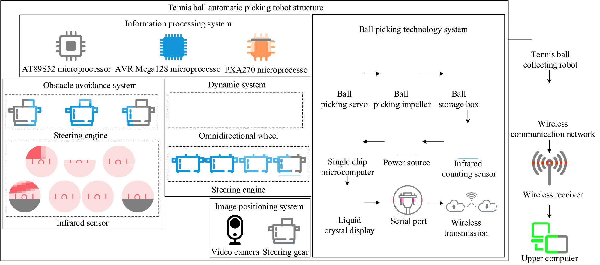
Tennis automatic ball-picking robot model.
As shown in Figure 1, the model consists of four parts: an automatic tennis ball-picking robot, a wireless communication network, a wireless network receiver, and an upper computer. Among them, the tennis automatic ball-picking robot consists of an information processing system, an image target detection and positioning system, an obstacle avoidance system, a power system, and a ball-picking technology system. The image object detection and positioning system includes a camera and a servo. The servo controls the camera to locate the sphere that needs to be collected at various angles. When the target sphere meets the image detection conditions, the robot adjusts its position to collect the sphere after calculating the position information and distance. The obstacle avoidance system consists of servo and infrared sensors, and four infrared sensors are selected to be arranged at the corners of the tennis ball-picking robot in each of the four directions. Three servos and three infrared sensors are selected and combined into a sensor with an angle and the ability to swing freely. When the sensor detects an obstacle, the robot automatically avoids it. The power system consists of four servos and four omnidirectional wheels. The servos are responsible for controlling the omnidirectional wheels and forming an angle with the front of the robot. The ball collection technology system includes a servo and wireless communication transmitter. The servo controls the impeller to collect the ball into the ball storage box while triggering a counting infrared sensor. The infrared counting sensor sends the recorded quantity to the microcontroller, which then displays the number of balls received through the LCD screen. The LCD screen sends data to the wireless communication transmitter through a serial port, and then the wireless communication receiver receives the data and sends it to the upper computer. The upper computer displays the acquired data to the operator, thereby achieving real-time monitoring and monitoring purposes. The information processing system consists of three microprocessors, which are responsible for controlling the counting and action operations during the robot’s ball collection process.
The process of an automatic tennis ball-picking robot is as follows. First, the infrared sensor and camera are used to locate the tennis ball to be collected at three different angles of 0°, 45°, and 90° in front of the robot. Second, the external features of the tennis ball, such as images and shapes, are collected and processed. Then, based on the processing results of the collected features, it determines whether it is the tennis ball that needs to be collected. If so, proceed with the collection. If not, proceed to the next step. After completing this series of actions, the robot switches its angle and moves forward 2 m, repeating the previous action in a loop until the end of one cycle. However, the positioning and picking cycle of the tennis ball-picking robot is within a range of 6 m², which poses a problem of long search time. Finding a method to improve the search efficiency of robots is of great significance. RFID technology has advantages such as fast recognition speed, high stability, and strong adaptability, and is widely used in fields such as intelligent robots and integrated circuits [20]. The structure of RFID technology is shown in Figure 2 [21].

The RFID system structure diagram.
As shown in Figure 2, RFID mainly consists of antennas, card readers, electronic tags, terminals, and middleware. The RFID operation process consists of three steps. First, the antenna transmits electronic tag position information and other data to the card reader. Second, the received information is transmitted to the middleware through the card reader, and the positioning algorithm in the middleware is used to calculate this information, thereby locating the radio frequency tag with this information and obtaining its position information. Finally, the middleware will transmit the obtained radio frequency tag position to the terminal, and the terminal will display the positioning result of this tag on the display. In addition, the terminal is also responsible for storing the historical data information of each label. Due to the indoor environment and numerous obstacles in tennis, the calculation of RFID signal path loss adopts an attenuation factor propagation model, and the basic formula is shown in Eq. (1):
In Eq. (1),
In Eq. (2)
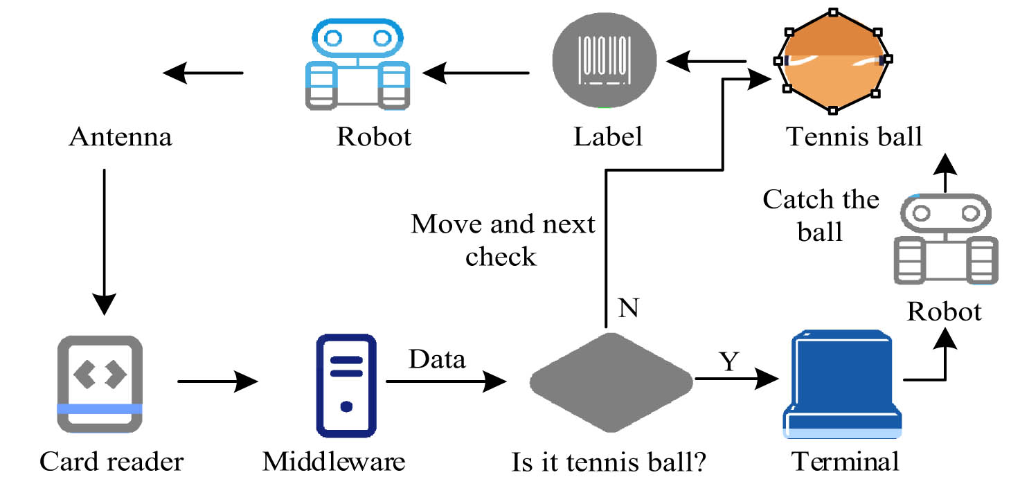
RFID-based tennis ball-picking robot model.
As shown in Figure 3, the specific operation process of the model is as follows. First, the robot obtains tennis ball images and other information through sensors and cameras and then transmits them to the card reader through antennas. Then, the card reader sends the information to the middleware, which processes the image information through algorithms and makes judgments on the processed image information. If the image information matches the set tennis ball information, the information will be transmitted to the terminal, and the ball-picking situation will be counted and stored. The terminal will issue a ball-picking command to the robot, and the robot will receive the ball. After picking it, the robot will continue with the next ball-picking operation. Otherwise, the robot will move forward to the next picking range to receive the ball until the end.
2.2 Design of a tennis automatic ball-picking robot model incorporating an improved LANDMARC algorithm
Due to the complex indoor environment, it is difficult for RFID systems to accurately locate the position of the sphere, resulting in a decrease in the accuracy of robot positioning when picking the ball. Therefore, finding an effective indoor positioning algorithm is of great significance for robots to accurately locate the position of the sphere. The LANDMARC algorithm is a positioning algorithm that uses computer vision and machine learning techniques to establish a visual map of indoor landmarks and determine the position of objects based on the map. It has the advantages of adaptive environmental changes and real-time acquisition of RSSIs and is widely utilized in the field of indoor positioning. The LANDMARC algorithm process is shown in Figure 1.
As shown in Figure 4, the process of the LANDMARC algorithm consists of three steps. First, the position of the RL and the strength of the received signal are obtained, and then the strength of the received signal of the tag to be located is obtained. Second, it calculates the Euclidean distance between the target label (TL) and the RL. Then, it obtains
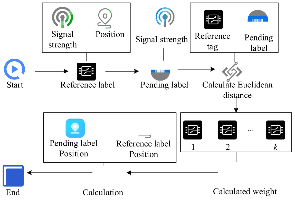
Flowchart of the LANDMARC algorithm.
In Eq. (3),
In Eq. (4),
In Eq. (5),
The calculation formula for the final system error estimation of
In Eq. (7),
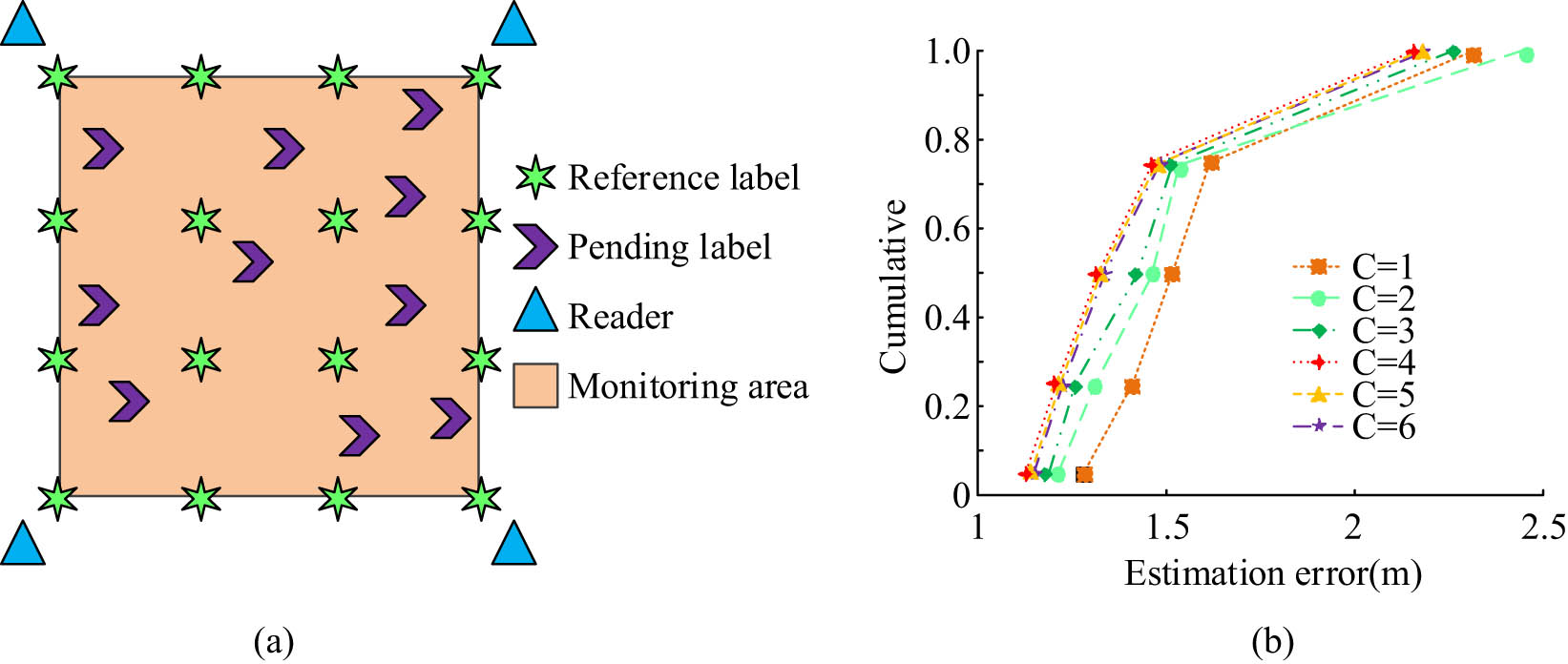
Error variation of LANDMARC algorithm under different numbers of adjacent RLs. (a) 6 × 6 Positioning system block diagram. (b) Different numbers of RL errors in the environment.
Figure 5(a) shows the specific layout structure of the LANDMARC positioning system is uniformly distributed by RLs in a 6 × 6 manner, with four readers distributed in four corners and positioning labels irregularly arranged in the monitoring area. Figure 5(b) shows that the error value of the LANDMARC algorithm increases with the increase of neighboring labels
In Eq. (9),
In Eq. (10),
In Eq. (11),
In Eq. (12),
In Eq. (13),
In Eq. (14),
In Eqs. (14) and (15),

The flow chart of the improved LANDMARC algorithm.
As shown in Figure 6, the calculation process of this algorithm first treats both the RL and virtual RL as virtual RLs, and obtains their RSSI values and coordinate positions. Second, it obtains the RSSI value of the label to be located and calculates the Euclidean distance between the label to be located and the virtual RL. Then, a weighted factor is taken to assign weight correction coefficients to each virtual RL, and neighboring labels are obtained by calculating the weight of the virtual RL. Finally, the position of the label to be located is calculated based on the position of the virtual RL. Finally, this study introduces the improved LANDMARC algorithm into the RFID system and applies the system to the tennis automatic ball-picking robot model. A tennis automatic ball-picking robot model based on the improved LANDMARC algorithm and RFID technology is constructed, and its structure is denoted in Figure 7.
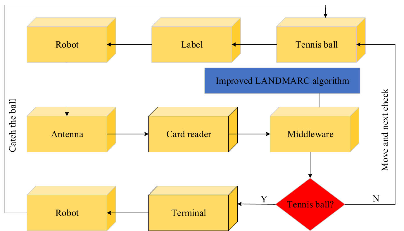
A tennis ball-picking robot model based on improved LANDMARC algorithm and RFID technology.
From Figure 7, the specific process of the model is as follows. First, the robot performs image detection on the labeled tennis balls and transmits the detection information to the card reader through an antenna. Then, it writes the improved LANDMARC algorithm middleware for calculation, determines whether the image is a tennis ball after calculation, and if so, it will send the information to the terminal for counting while the robot collects the ball. If it is not a tennis ball, the robot will move to the next range to continue the first step. In this study, to improve RFID, the coefficient is first introduced by the factor-weighted method, and the weight allocation of the LANDMARC algorithm is improved. Second, virtual RLs are introduced into the LANDMARC algorithm to reduce the number of real labels and improve positioning accuracy and efficiency. Then, the LANDMARC algorithm, which has been improved twice, is introduced into RFID middleware. Finally, when RFID uses tags for positioning, the positioning is improved through middleware calculation and processing. The effective frequency and interface of the RFID tag reader are 308 MHz and 802.11b interfaces, respectively, and have eight measurable power energy levels. The electronic tag is an active electronic tag with an average transmission interval of 7.5 s and a 7-bit ID. The maximum read and write distance of the label is about 45.71 m, and the reading range of the card reader can be expanded to 304.7 m by the antenna. In an indoor environment with an area of 6 m × 6 m, the layout density unit positioning grid is divided into four RLs, and the virtual RLs are evenly arranged in a 4 × 4 network structure.
3 Results
3.1 Performance comparison testing of the improved LANDMARC algorithm
To prove the superiority of the improved LANDMARC algorithm (Algorithm 1) proposed in the study, it was experimentally compared with the improved PSO (Algorithm 2), BP-LANDMARC (Algorithm 3), and Harris-SIFT algorithm (Algorithm 4) in Matlab simulation software. The improved PSO algorithm overcomes the defects of premature convergence and improves the computational efficiency and convergence speed of the algorithm, but it still has the disadvantages of high computational cost and cannot guarantee optimal conditions in all cases. The advantage of the BP-LANDMARC algorithm is to realize the region adaptive positioning function of pending labels, reduce the introduction of interference RLs, and improve the accuracy of pending labels. Its disadvantages are low training efficiency and slow convergence speed. Although the Harris-SIFT algorithm has the advantages of simple computation and insensitive viewpoint transformation, it still has some shortcomings, such as the slow computation speed. The experimental environment was set as the number of adjacent virtual RLs was 4, the number of unpositioned labels was 10, the number of robots was 4, and the experimental area was a monitoring area of 6 m × 6 m. The experimental indicators included error value, accuracy, and running time. The specific experimental environment for this study is shown in Table 1.
Experimental environment configuration
| Parameter names | Parameter |
|---|---|
| Processor | Intel Core i9-13900K |
| Main frequency | 5.8 Hz |
| Internal memory | 32 GB |
| Hard disk capacity | 500 GB |
| Operating system | Windows 10 64 |
| Matlab version | Matlab 2023b |
| Data analysis software | Matlab 2023b |
In the above environment, first, comparative experiments were conducted on the error values and accuracy of the four algorithms under different neighboring label densities. The error values and accuracy results of each algorithm are shown in Figure 8.
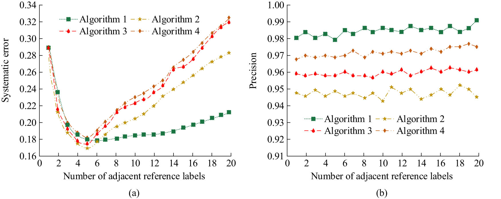
Comparison results of error values and precision of each algorithm under different neighboring tag densities. (a) The error value of each algorithm with a different number of neighboring RLs. (b) The precision of each algorithm with a different number of neighboring RLs.
As shown in Figure 8(a), the error value curve of Algorithm 1 was at its lowest point when the number of adjacent RLs was 8 and was in the range of 0.18–0.21. When the number of adjacent RLs was 20, the error value was 0.21. The error value curve of Algorithm 2 had the lowest number of adjacent RLs in the range of 0–5 and then rapidly increased higher than Algorithm 2. Moreover, when the number of adjacent RLs was 20, the error value was 0.21. Algorithm 3 had an error value of 0.31 when the number of adjacent RLs was 20. Algorithm 4 had an error value of 0.32 when the number of adjacent RLs was 20. From Figure 8(b), the average precision of Algorithm 1 was 0.983, which was significantly higher than the other algorithms. The average precision of Algorithm 2 was 0.947, Algorithm 3 was 0.958, and Algorithm 4 was 0.959. The above results indicate that from the dimensions of precision and error value, Algorithm 1 proposed in the study performs better than the comparison algorithm. The comparison results of the running time and accuracy of each algorithm are shown in Figure 9.
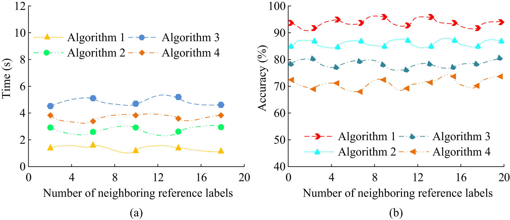
Comparison results of the running time and accuracy of each algorithm. (a) Each algorithm detects the running time. (b) Comparison result of prediction accuracy of each algorithm.
From Figure 9(a), the average running time of Algorithm 1 was 1.36 s, which was lower than 2.97 s of Algorithm 2, 4.74 s of Algorithm 3, and 3.89 s of Algorithm 4. In Figure 9(b), the average accuracy of Algorithm 1 was 94.6%, which was higher than 86.7% of Algorithm 2, 79.6% of Algorithm 3, and 72.8% of Algorithm 4. The above results indicated that from the dimensions of runtime and accuracy, the proposed Algorithm 1 performs better than other algorithms. The comparison results of the mean square error (MSE) and root mean square error (RMSE) of each algorithm are shown in Figure 10.

Comparison results of MSE and RMSE of each algorithm. (a) Positioning error of each algorithm. (b) Each algorithm locates the error root.
From Figure 10(a), the MSE of Algorithm 1 was 0.083, Algorithm 2 was 0.142, Algorithm 3 was 0.226, and Algorithm 4 was 0.309. Among them, Algorithm 1 had the lowest MSE. From Figure 10(b), the RMSE values of Algorithms 1, 2, 3, and 4 were 0.798, 0.136, 0.216, and 0.306, respectively. Among them, Algorithm 1 had the lowest RMSE. In addition, to further verify the superiority of the proposed algorithms, a comparison experiment on response time, computational complexity, and energy consumption was also carried out for each algorithm. The index was the comparison results of response time, time complexity, and CUP usage, and the specific results are shown in Table 2.
Comparison of the response time, time complexity, and CUP usage of each algorithm
| Algorithm | Response time (s) | Average time complexity | CPU usage (%) |
|---|---|---|---|
| Algorithm 1 | 0.14 s | O(1) | 7.26 |
| Algorithm 2 | 0.18 s | O(n) | 16.24 |
| Algorithm 3 | 0.21 s | O(log 2n) | 10.28 |
| Algorithm 4 | 0.24 s | O(n) | 18.73 |
| P < 0.05 | P < 0.05 | P < 0.05 |
From Table 2, the response time, time complexity, and CUP usage of Algorithm 1 proposed in this study were 0.14 s, O(1), and 7.26%, respectively, which were superior to those of the comparison algorithms. The above results showed that the performance of the proposed algorithm was significantly better than that of the comparison algorithms in terms of response time, time complexity, and CUP usage. The above results indicated that from the dimensions of MSE and RMSE, the proposed Algorithm 1 had significantly better positioning accuracy than comparison algorithms. In summary, from the dimensions of MSE, RMSE, running time, accuracy, and precision, the algorithm proposed in the study performs better than the comparative algorithms, indicating its effectiveness.
3.2 Analysis of the application effect of the tennis automatic ball-picking robot model
To verify the performance superiority of the proposed tennis automatic ball-picking robot model (Model 1), comparative experiments were conducted with the improved PSO-based tennis automatic ball-picking robot model (Model 2), the BP-LANDMARC-based tennis automatic ball-picking robot model (Model 3), and the Harris-SIFT-based tennis automatic ball-picking robot model (Model 4). The robot collected the ball by targeting the nearest sphere detected within its field of view. To verify its stability and detection accuracy, a study was conducted by placing four tennis balls in different positions, allowing four model robots to collect the ball from the starting point, and conducting a comparative experiment on the trajectory of the ball collection action. The comparison results of the picking trajectory of each model robot are shown in Figure 11.
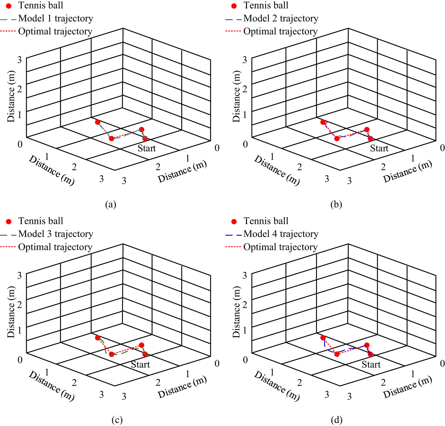
Comparison results of ball collecting action trajectories of each model robot: (a) Model 1, (b) Model 2, (c) Model 3, and (d) Model 4.
From Figure 11(a), the Model 1 robot’s ball-picking action trajectory and optimal trajectory fitted best; the walking path was close to the optimal path, the straight-line curvature was the lowest, and the target detection and positioning were the most stable. From Figure 11(b), the motion trajectory of Model 2 fitted well with the optimal trajectory, but there was a slight curvature in the latter half, and there was a deviation in the positioning of the last ball, resulting in poor motion stability. From Figure 11(c), the action trajectory of Model 3 fitted well with the optimal trajectory in the first segment, with some deviation in the second and third segments and a deviation in the positioning of the second ball, resulting in poor stability of its action. From Figure 11(d), Model 4 had the worst action trajectory in the second and third segments, and there was a significant deviation in the positioning of the third ball. The above results indicate that during the process of the robot detecting and locating the sphere, moving forward, and finally picking the sphere, the signal reception strength is interfered with, resulting in positioning deviation during the journey. Model 1 robot performed better than the comparison model robot, and it had good performance in object detection and positioning. At the same time and in the same environment, the comparison results of the tennis recognition rate and ball-picking speed of each model robot are shown in Figure 12.
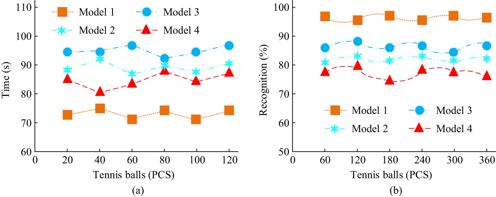
Comparison of accuracy rate and picking speed of each model robot. (a) Ball receiving speed of each model robot. (b) Each model robot recognizes tennis ball accuracy.
As shown in Figure 12(a), Model 1 received the most balls at the same time, with an average picking speed of 3.72 s per ball, Model 2 had an average picking speed of 4.62 s per ball, Model 3 had an average picking speed of 4.71 s per ball, and Model 4 had an average picking speed of 4.03 s per ball. As shown in Figure 12(b), the average recognition rate of tennis balls in Model 1 was 99.7%, the average recognition rate of robot tennis balls in Model 2 was 89.9%, the average recognition rate of tennis balls in Model 3 was 81.7%, and the average recognition rate of tennis balls in Model 4 was 78.9%. Among them, the average recognition rate of tennis balls in Model 1 was the highest. The above results indicate that, from the dimensions of ball-picking speed and tennis recognition rate, the performance of Model 1 proposed in the study is significantly better than that of the comparative model. A monitoring area of 6 m × 6 m was selected, RLs were arranged in a 5 × 5 grid shape and it randomly distributed ten labels to be located. At the same time, the positioning accuracy of four model robots was analyzed, with four adjacent RLs. The positioning results of each model are shown in Figure 13.
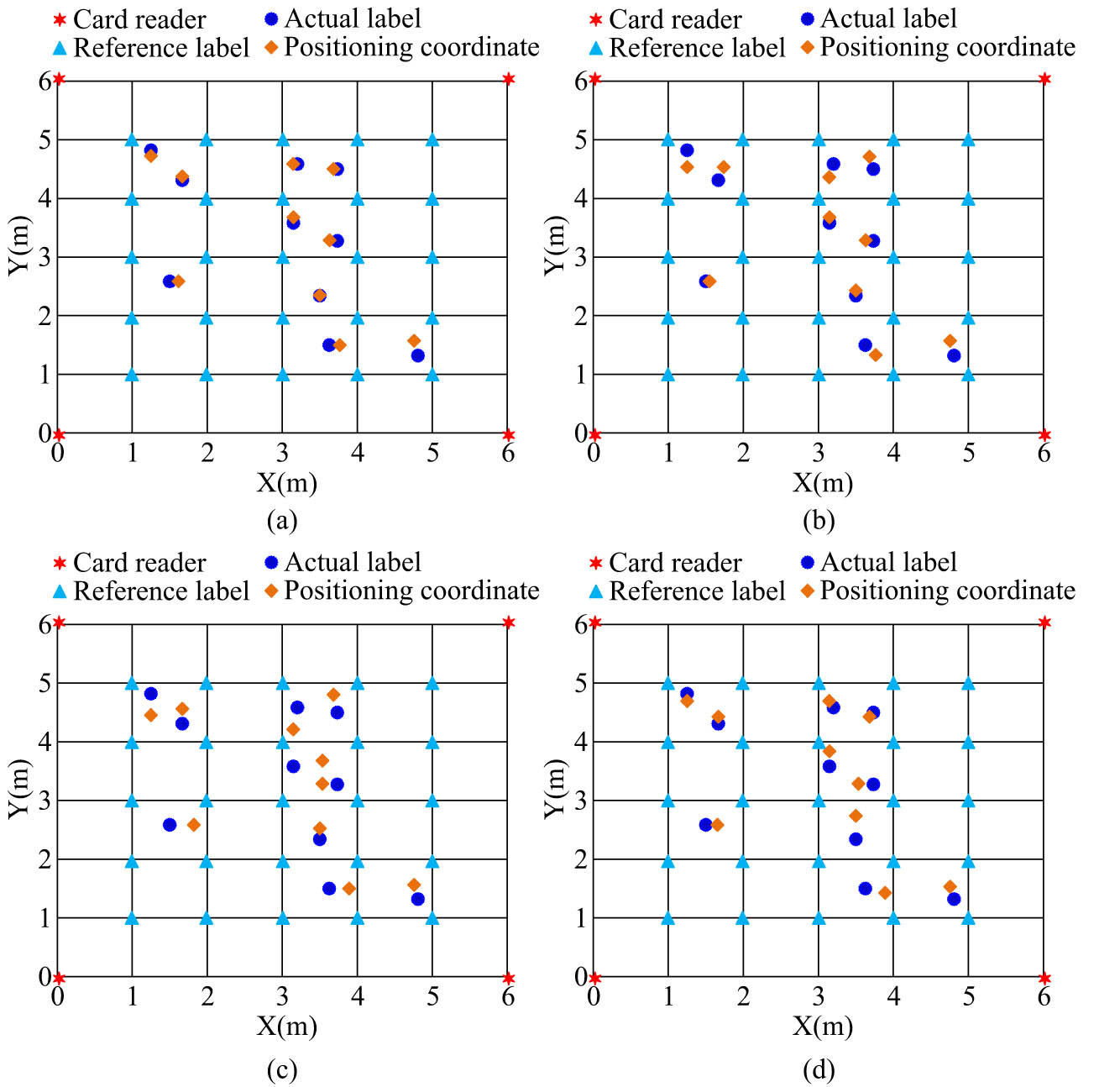
Positioning results of each model: (a) Model 1, (b) Model 2, (c) Model 3, and (d) Model 4.
As shown in Figure 13(a), the positioning coordinates of Model 1 were mostly close to the actual coordinates, with the smallest position error and the most accurate positioning. The positioning coordinates of Model 2 had three significant errors compared to the actual coordinates, but overall, the positioning was more accurate. The overall error between the positioning coordinates of Model 3 and the actual coordinates was the largest, and the positioning effect was the worst. There were four significant errors between the positioning coordinates of Model 4 and the actual coordinates, and its positioning accuracy was average. The above results indicate that under the same number of RLs and adjacent labels, the proposed Model 1 has the most accurate localization and practicality. There are many obstacles in indoor tennis, and the automatic ball-picking robot will inevitably encounter obstacles during the ball-picking process. It was compared with other models for obstacle avoidance experiments. The comparative experimental results of obstacle avoidance for each model are shown in Figure 14.
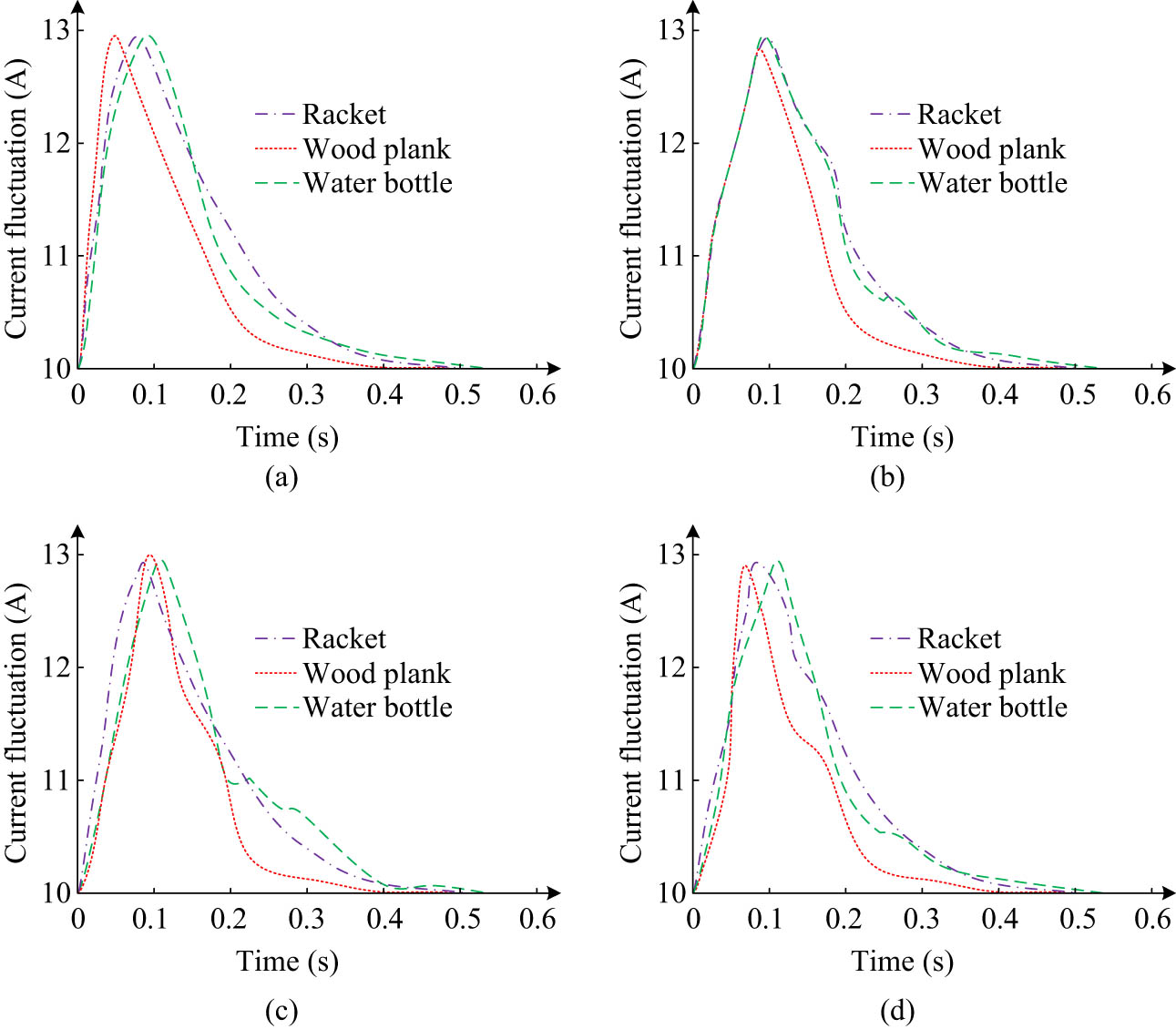
Experimental results of obstacle avoidance comparison among different models: (a) Model 1, (b) Model 2, (c) Model 3, and (d) Model 4.
As shown in Figure 14(a), Model 1 took 0.33, 0.28, and 0.19 s to avoid the racket, wooden board, and water bottle, respectively, and quickly resumed normal walking. As shown in Figure 14(b), Model 2 took 0.41, 0.35, and 0.23 s to avoid the racket, wooden board, and water bottle, respectively, and resumed normal walking speed slightly slower. As shown in Figure 14(c), Model 3 took 0.51, 0.36, and 0.29 s, respectively, to avoid the racket, wooden board, and water bottle, and the recovery of normal walking speed was relatively slow. The above results indicate that from the perspective of obstacle avoidance, Model 1 proposed in the study performs better than the comparative model. In summary, from the dimensions of obstacle avoidance, ball collection trajectory, coordinate positioning, etc., the performance of Model 1 proposed in the study is superior to the comparative model, indicating that the model is effective and practical. The comparison results of ball collection and real-time rate of each model are shown in Figure 15.
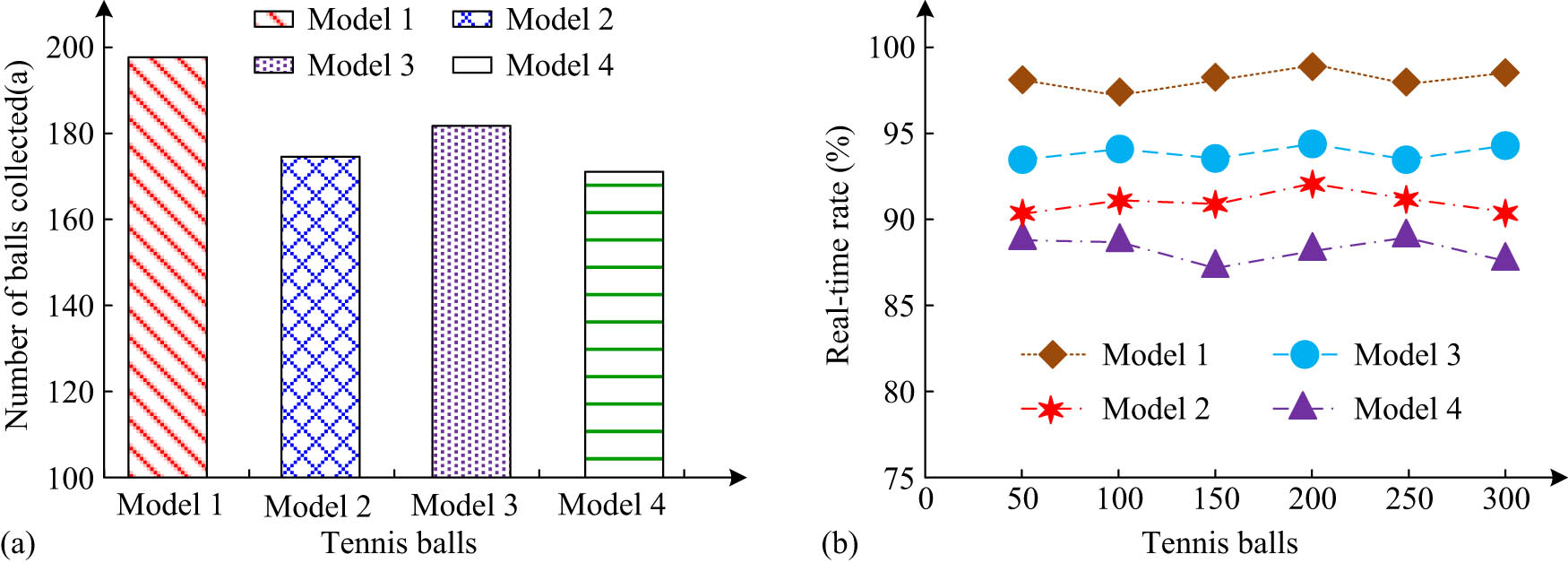
Comparison results of balls collected and real-time rates for each model. (a) Comparison of the number of balls collected by each model. (b) Real-time rate comparison results of each model.
As shown in Figure 15(a), among the 200 balls, Model 1 had the highest number of balls (198), Model 2 had 176, Model 3 had 183, and Model 4 had 175. As shown in Figure 15(b), the real-time ball collection rates of Model l, Model 2, Model 3, and Model 4 were 96.9, 90.4, 94.8, and 89.9%, respectively, among which Model 1 proposed in the study had the highest real-time ball collection rate. From the above results, the performance of the proposed Model 1 was superior to the comparison model in terms of the number of successful ball collections and real-time ball collection rate. In addition, to ensure the effectiveness and credibility of the experiment, statistical analysis was made on each algorithm according to each experimental index. The significance of the performance difference among the comparison algorithms was represented by the P-value. When the P-value was less than 0.05, the performance difference between the algorithms was significant, as shown in Table 3.
Partial results of statistical analysis among algorithms and models
| Algorithms | Average precision | Average accuracy | MSE | Model | Average receiving speed | Tennis ball average recognition rate |
|---|---|---|---|---|---|---|
| Algorithm 1 | 0.983 | 94.6% | 0.083 | Model 1 | 3.72 s/a | 99.7% |
| Algorithm 2 | 0.947 | 86.7% | 0.142 | Model 2 | 4.62 s/a | 48.90% |
| Algorithm 3 | 0.958 | 79.6% | 0.226 | Model 3 | 4.71 s/a | 89.9% |
| Algorithm 4 | 0.959 | 72.8% | 0.309 | Model 4 | 4.03 s/a | 78.9% |
| P < 0.05 | P < 0.05 | P < 0.05 | P < 0.05 | P < 0.05 |
From Table 3, there were significant differences in statistical analysis among algorithms during comparison experiments, indicating that the experiment of this study is credible.
4 Discussion
This study conducted a comparative experimental analysis on the performance of the improved LANDMARC algorithm and compared the application effect of the tennis automatic ball-picking robot model based on the improved LANDMARC algorithm and RFID technology. The experiment findings indicated that the improved LANDMARC algorithm had significant advantages in terms of accuracy, precision, and error value. In the precision comparison experiment, the average precision of the improved LANDMARC, improved PSO, BP-LANDMARC, and Harris-SIFT algorithms were 0.983, 0.947, 0.958, and 0.959, respectively. Among them, the improved LANDMARC algorithm proposed in the study had the highest precision, indicating that the introduction of weighting factors improved the precision of the algorithm and optimized its performance. This result is consistent with the improved LANDMARC algorithm proposed by Kang et al. [23]. This result indicated that the improved LANDMARC algorithm had high effectiveness in image target localization in real-world applications. In the accuracy comparison experiment, the average accuracy and the average running time of the improved LANDMARC, improved PSO, BP-LANDMARC, and Harris-SIFT algorithms were 94.6, 86.7, 79.6, and 72.8%; the average running time was 1.36, 2.97, 4.74, and 3.89 s. Among them, the improved LANDMARC algorithm proposed in the research had the highest accuracy, indicating that the introduction of virtual reference tags improved the image target detection and positioning accuracy of the algorithm, and the algorithm was optimized again on the basis of the introduction of weighted factors. This result is the same as that of the improved LANDMARC algorithm proposed by Zhao et al. [24]. The improved LANDMARC algorithm proposed in this study had the lowest running time and the highest operational efficiency. This showed that the introduction of the weighting factor and virtual RL improved the efficiency of the algorithm in detecting and locating target images. This result coincides with the improved LANDMARC algorithm proposed by Sanchez et al. [25]. In addition, in the MSE and RMSE comparison experiment, the MSE and RMSE results of the improved LANDMARC algorithm were 0.083 and 0.798, respectively, and its performance was significantly superior to other algorithms, which indicated that the algorithm reduced systematic error. This result is similar to that of the improved LANDMARC algorithm proposed by Wu et al. in 2023 [26]. Second, in the comparative analysis of the application effects of the tennis automatic ball-picking robot model, it was found that the tennis automatic ball-picking robot based on the improved LANDMARC algorithm RFID showed good application effects in the ball-picking action trajectory, tennis recognition rate, ball-picking speed, and obstacle avoidance. In the comparative experiment of ball collection action trajectory, the proposed tennis automatic ball-picking robot’s action path was fitted with the optimal path, and its detection and positioning performance for tennis was better than that of the comparative robot. The introduction of RFID technology has improved the positioning performance of robots. This result is similar to the conclusion drawn by Figat and Zieliński in 2023 [27]. In the comparative experiment of tennis recognition rate and ball-picking speed, the recognition rate and ball-picking speed of the proposed tennis automatic ball-picking robot were 99.7% and 3.72 s/piece, respectively. The results showed that combining the improved LANDMARC algorithm with RFID technology improved the recognition rate of the tennis ball-picking robot for target detection and optimized the ball-picking speed. This result is similar to the conclusion drawn by Alshammari et al. [28]. In the obstacle avoidance comparative experiment, the tennis automatic ball-picking robot proposed in the study showed good performance and quickly resumed normal operation in 0.33, 0.28, and 0.19 s after avoiding the racket, wooden board, and water bottle, respectively. This result is very different from the conclusion drawn by Zeng et al. [29]. This result indicated that the tennis automatic ball collection robot based on the improved LANDMARC algorithm and RFID technology had good performance and practicality. In the real environment, a variety of challenges will be faced, such as facing an indoor environment with strong signal interference. Because there is signal interference between reference tags, positioning is usually not allowed through a large number of deployments. The higher the deployment density, the stronger the interference between each other. Thus, the improved LANDMARC algorithm is proposed to use virtual reference tags to reduce signal interference. The reason is that the virtual RL and the real RL have the same characteristics, but its field strength multichannel stiffness loss model is calculated; there is no real signal interference, so as to reduce the real RL to reduce signal interference. In addition, the proposed system can be applied to indoor ball-collecting robots such as table tennis and badminton. For example, the RFID system is used to locate the table tennis. The way is to use the infrared counter, wireless communication network, wireless network receiver, and host computer of the system to cooperate. By using the automatic ball collecting robot of a tennis ball, the information processing system, image target detection and positioning system, obstacle avoidance system, dynamic system, and ball picking technology system are used to detect and locate the target of a table tennis ball. The RFID system based on the improved LANDMARC algorithm is used for table tennis positioning and search. Electronic tags are placed in the table tennis, the information obtained is received by the antenna, and the position is located by the middleware. The robot takes the ball-collecting action to collect the ball.
5 Conclusions
Aiming at the problem of inaccurate target detection and positioning of automatic tennis ball-picking robots at present, this study proposed a method that combines image target detection and RFID technology and introduced the LANDMARC algorithm to increase the accuracy of RFID technology positioning. The LANDMARC algorithm was also improved by introducing weighted factors and virtual RLs. In addition, to achieve accurate positioning and ball-picking of the automatic tennis robot, this method was applied to the tennis automatic ball-picking robot, and a tennis automatic ball-picking robot model based on improved LANDMARC algorithm and RFID technology was constructed. Through comparative analysis of algorithms, it was found that the improved LANDMARC algorithm proposed in the study had significantly better performance than the comparison algorithms in terms of runtime, accuracy, and other dimensions. Among them, in the accuracy comparison test, the average accuracy of the improved LANDMARC, improved PSO, BP-LANDMARC, and Harris-SIFT algorithms were 94.6, 86.7, 79.6 and 72.8%, respectively, among which the improved LANDMARC algorithm proposed in the study had the highest accuracy. It is shown that the introduction of virtual reference tags improves the accuracy of image target detection and positioning, and the algorithm is optimized again based on the introduction of weighted factors. Subsequently, through comparative experiments on the application effects of the tennis automatic ball-picking robot model, it was found that from the dimensions of obstacle avoidance, ball-picking path, and ball-picking speed, the tennis automatic ball-picking robot model based on the improved LANDMARC algorithm and RFID technology proposed in the study had high practicality and performance, which helps to improve the development of image detection and positioning of ball automatic ball-picking robots. The shortcomings of this study lie in the fact that the actual outdoor environment has a more complex impact on robot image target detection and localization, and considering a more complex real environment is a further direction of research.
-
Funding information: Authors state no funding involved.
-
Author contributions: Yaqiao Huang: study design, data collection, statistical analysis, visualization, writing, and revision of the original draft. Yu Xiang: revision of the manuscript and supervision. The final draft was verified by all authors before submission. All authors have accepted responsibility for the entire content of this manuscript and approved its submission.
-
Conflict of interest: Authors state no conflict of interest.
-
Data availability statement: The datasets generated during and/or analyzed during the current study are available from the corresponding author on reasonable request.
References
[1] Ye C, Zhu R, Ma J, Huang H, Li X, Wen J. Comprehensive tennis serve training system based on local attention-based CNN model. IEEE Sens J. 2024;24(7):11917–26. 10.1109/JSEN.2024.3366781.Search in Google Scholar
[2] Groumpos PP. A critical historic overview of artificial intelligence: issues, challenges, opportunities, and threats. AIA. 2023;1(4):197–213. 10.47852/bonviewAIA3202689.Search in Google Scholar
[3] Büchler D, Guist S, Calandra R, Berenz V, Schölkopf B, Peters J. Learning to play table tennis from scratch using muscular robots. IEEE Trans Robot. 2022;38(6):3850–60. 10.1109/TRO.2022.3176207.Search in Google Scholar
[4] Jin L, Zhang G, Wang Y, Li S. RNN-based quadratic programming scheme for tennis-training robots with flexible capabilities. IEEE Trans Syst Man Cybern Syst. 2023;53(2):838–47. 10.1109/TSMC.2022.3188700.Search in Google Scholar
[5] Su J, Wang L, Liu C, Qiao H. Robotic inserting a moving object using visual-based control with time-delay compensator. IEEE Trans Ind Inf. 2024;20(2):1842–52. 10.1109/TII.2023.3282320.Search in Google Scholar
[6] Wang X. Tennis robot design via internet of things and deep learning. IEEE Access. 2021;9:127460–70. 10.1109/ACCESS.2021.3111706.Search in Google Scholar
[7] Kobayashi R, Nabae H, Suzumori K. Active-bending six-bar tensegrity modular robot driven by thin artificial muscles. IEEE Robot Autom Lett. 2023;8(11):7400–7. 10.1109/LRA.2023.3315537.Search in Google Scholar
[8] Yang L, Zhang H, Zhu X, Sheng X. Ball motion control in the table tennis robot system using time-series deep reinforcement learning. IEEE Access. 2021;9:99816–27. 10.1109/ACCESS.2021.3093340.Search in Google Scholar
[9] Koskinopoulou M, Raptopoulos F, Papadopoulos G, Mavrakis N, Maniadakis M. Robotic waste sorting technology: toward a vision-based categorization system for the industrial robotic separation of recyclable waste. IEEE Robot Autom Mag. 2021;28(2):50–60. 10.1109/MRA.2021.3066040.Search in Google Scholar
[10] Motroni A, Bernardini F, Buffi A, Nepa P, Tellini B. A UHF-RFID multi-antenna sensor fusion enables item and robot localization. IEEE J Radio Freq Ident. 2022;6(3):456–66. 10.1109/JRFID.2022.3166354.Search in Google Scholar
[11] Gunatilake A, Kodagoda S, Thiyagarajan K. Battery-free UHF-RFID sensors-based SLAM for in-pipe robot perception. IEEE Sens J. 2022;22(20):20019–26. 10.1109/JSEN.2022.3204682.Search in Google Scholar
[12] Haibi A, Oufaska K, Yassini KE, Boulmalf M, Bouya M. Systematic mapping study on RFID technology. IEEE Access. 2022;10:6363–80. 10.1109/ACCESS.2022.3140475.Search in Google Scholar
[13] Cheng MM, Zhang J, Wang DG, Tan W, Yang J. A localization algorithm based on improved water flow optimizer and max-similarity path for 3-D heterogeneous wireless sensor networks. IEEE Sens J. 2023;23(12):13774–88. 10.1109/JSEN.2023.3271820.Search in Google Scholar
[14] Yao C, Sun Z, Xu S, Zhang H, Ren G, Ma G. ANN optimization of weighting factors using genetic algorithm for model predictive control of PMSM drives. IEEE Trans Ind Appl. 2022;58(6):7346–62. 10.1109/TIA.2022.3190812.Search in Google Scholar
[15] Zhao S, Liu B, Chi Z, Li T, Li S. Characteristics based fire detection system under the effect of electric fields with improved YOLO-v4 and ViBe. IEEE Access. 2022;10:81899–909. 10.1109/ACCESS.2022.3190867.Search in Google Scholar
[16] Peng C, Jiang H, Qu L. Deep convolutional neural network for passive RFID tag localization via joint RSSI and PDOA fingerprint features. IEEE Access. 2021;9:15441–51. 10.1109/ACCESS.2021.3052567.Search in Google Scholar
[17] Della Santina C, Duriez C, Rus D. Model-based control of soft robots: a survey of the state of the art and open challenges. IEEE Control Syst Mag. 2023;43(3):30–65. 10.1109/MCS.2023.3253419.Search in Google Scholar
[18] Gunatilake A, Kodagoda S, Thiyagarajan K. A novel UHF-RFID dual antenna signals combined with Gaussian process and particle filter for in-pipe robot localization. IEEE Robot Autom Lett. 2022;7(3):6005–11. 10.1109/LRA.2022.3163769.Search in Google Scholar
[19] Mostaccio A, Bianco GM, Marrocco G, Occhiuzzi C. RFID technology for food industry 4.0: a review of solutions and applications. IEEE J Radio Freq Ident. 2023;7(2):145–57. 10.1109/JRFID.2023.3278722.Search in Google Scholar
[20] Duan X, Kang L, Zhou H, Liu Q. Multivector model predictive power control with low computational burden for grid-tied quasi-Z-source inverter without weighting factors. IEEE Trans Power Electron. 2022;37(10):11739–48. 10.1109/TPEL.2022.3174303.Search in Google Scholar
[21] Tian C, Ma Y, Wang B. Cooperative localization for passive RFID backscatter networks and theoretical analysis of performance limit. IEEE Trans Wirel Commun. 2023;22(2):1388–402. 10.1109/TWC.2022.3204679.Search in Google Scholar
[22] Liu Y, Chen R, Zhou Y, Liu M, Hui Y, Cheng N. RFID-based vehicle localization using virtual wideband multi-frequency continuous wave. IEEE J Radio Freq Ident. 2023;7:222–32. 10.1109/JRFID.2023.3287327.Search in Google Scholar
[23] Kang S, Lee M, Kim M, Shim H. HybridMatch: semi-supervised facial landmark detection via hybrid heatmap representations. IEEE Access. 2023;11:26125–35. 10.1109/ACCESS.2023.3257180.Search in Google Scholar
[24] Zhao Y, Liu X, Chen L, Li Q, Han P. Salaft: an RFID-based item-level localization algorithm with fluctuation textures. IEEE Sens J. 2024;24(6):8870–84. 10.1109/JSEN.2024.3355245.Search in Google Scholar
[25] Sanchez SA, van Overschelde P, Vandemeulebroucke J. Segmentation-guided coordinate regression for robust landmark detection on X-rays: application to automated assessment of lower limb alignment. IEEE Access. 2024;12:61484–97. 10.1109/ACCESS.2024.3394895.Search in Google Scholar
[26] Wu C, Gong Z, Tao B, Tan K, Gu Z, Yin ZP. RF-SLAM: UHF-RFID based simultaneous tags mapping and robot localization algorithm for smart warehouse position service. IEEE Trans Ind Inf. 2023;19(12):11765–75. 10.1109/TII.2023.3252405.Search in Google Scholar
[27] Figat M, Zieliński C. Synthesis of robotic system controllers using robotic system specification language. IEEE Robot Autom Lett. 2023;8(2):688–95. 10.1109/LRA.2022.3229231.Search in Google Scholar
[28] Alshammari RFN, Arshad H, Rahman AHA, Albahri OS. Robotics utilization in automatic vision-based assessment systems from artificial intelligence perspective: a systematic review. IEEE Access. 2022;10:77537–70. 10.1109/ACCESS.2022.3188264.Search in Google Scholar
[29] Zeng C, Li Y, Guo J, Huang Z, Wang N, Yang C. A unified parametric representation for robotic compliant skills with adaptation of impedance and force. IEEE-ASME Trans Mechatron. 2022;27(2):623–33. 10.1109/TMECH.2021.3109160.Search in Google Scholar
© 2025 the author(s), published by De Gruyter
This work is licensed under the Creative Commons Attribution 4.0 International License.
Articles in the same Issue
- Research Articles
- Generalized (ψ,φ)-contraction to investigate Volterra integral inclusions and fractal fractional PDEs in super-metric space with numerical experiments
- Solitons in ultrasound imaging: Exploring applications and enhancements via the Westervelt equation
- Stochastic improved Simpson for solving nonlinear fractional-order systems using product integration rules
- Exploring dynamical features like bifurcation assessment, sensitivity visualization, and solitary wave solutions of the integrable Akbota equation
- Research on surface defect detection method and optimization of paper-plastic composite bag based on improved combined segmentation algorithm
- Impact the sulphur content in Iraqi crude oil on the mechanical properties and corrosion behaviour of carbon steel in various types of API 5L pipelines and ASTM 106 grade B
- Unravelling quiescent optical solitons: An exploration of the complex Ginzburg–Landau equation with nonlinear chromatic dispersion and self-phase modulation
- Perturbation-iteration approach for fractional-order logistic differential equations
- Variational formulations for the Euler and Navier–Stokes systems in fluid mechanics and related models
- Rotor response to unbalanced load and system performance considering variable bearing profile
- DeepFowl: Disease prediction from chicken excreta images using deep learning
- Channel flow of Ellis fluid due to cilia motion
- A case study of fractional-order varicella virus model to nonlinear dynamics strategy for control and prevalence
- Multi-point estimation weldment recognition and estimation of pose with data-driven robotics design
- Analysis of Hall current and nonuniform heating effects on magneto-convection between vertically aligned plates under the influence of electric and magnetic fields
- A comparative study on residual power series method and differential transform method through the time-fractional telegraph equation
- Insights from the nonlinear Schrödinger–Hirota equation with chromatic dispersion: Dynamics in fiber–optic communication
- Mathematical analysis of Jeffrey ferrofluid on stretching surface with the Darcy–Forchheimer model
- Exploring the interaction between lump, stripe and double-stripe, and periodic wave solutions of the Konopelchenko–Dubrovsky–Kaup–Kupershmidt system
- Computational investigation of tuberculosis and HIV/AIDS co-infection in fuzzy environment
- Signature verification by geometry and image processing
- Theoretical and numerical approach for quantifying sensitivity to system parameters of nonlinear systems
- Chaotic behaviors, stability, and solitary wave propagations of M-fractional LWE equation in magneto-electro-elastic circular rod
- Dynamic analysis and optimization of syphilis spread: Simulations, integrating treatment and public health interventions
- Visco-thermoelastic rectangular plate under uniform loading: A study of deflection
- Threshold dynamics and optimal control of an epidemiological smoking model
- Numerical computational model for an unsteady hybrid nanofluid flow in a porous medium past an MHD rotating sheet
- Regression prediction model of fabric brightness based on light and shadow reconstruction of layered images
- Dynamics and prevention of gemini virus infection in red chili crops studied with generalized fractional operator: Analysis and modeling
- Qualitative analysis on existence and stability of nonlinear fractional dynamic equations on time scales
- Fractional-order super-twisting sliding mode active disturbance rejection control for electro-hydraulic position servo systems
- Analytical exploration and parametric insights into optical solitons in magneto-optic waveguides: Advances in nonlinear dynamics for applied sciences
- Bifurcation dynamics and optical soliton structures in the nonlinear Schrödinger–Bopp–Podolsky system
- User profiling in university libraries by combining multi-perspective clustering algorithm and reader behavior analysis
- Review Article
- Haar wavelet collocation method for existence and numerical solutions of fourth-order integro-differential equations with bounded coefficients
- Special Issue: Nonlinear Analysis and Design of Communication Networks for IoT Applications - Part II
- Silicon-based all-optical wavelength converter for on-chip optical interconnection
- Research on a path-tracking control system of unmanned rollers based on an optimization algorithm and real-time feedback
- Analysis of the sports action recognition model based on the LSTM recurrent neural network
- Industrial robot trajectory error compensation based on enhanced transfer convolutional neural networks
- Research on IoT network performance prediction model of power grid warehouse based on nonlinear GA-BP neural network
- Interactive recommendation of social network communication between cities based on GNN and user preferences
- Application of improved P-BEM in time varying channel prediction in 5G high-speed mobile communication system
- Construction of a BIM smart building collaborative design model combining the Internet of Things
- Optimizing malicious website prediction: An advanced XGBoost-based machine learning model
- Economic operation analysis of the power grid combining communication network and distributed optimization algorithm
- Sports video temporal action detection technology based on an improved MSST algorithm
- Internet of things data security and privacy protection based on improved federated learning
- Enterprise power emission reduction technology based on the LSTM–SVM model
- Construction of multi-style face models based on artistic image generation algorithms
- Research and application of interactive digital twin monitoring system for photovoltaic power station based on global perception
- Special Issue: Decision and Control in Nonlinear Systems - Part II
- Animation video frame prediction based on ConvGRU fine-grained synthesis flow
- Application of GGNN inference propagation model for martial art intensity evaluation
- Benefit evaluation of building energy-saving renovation projects based on BWM weighting method
- Deep neural network application in real-time economic dispatch and frequency control of microgrids
- Real-time force/position control of soft growing robots: A data-driven model predictive approach
- Mechanical product design and manufacturing system based on CNN and server optimization algorithm
- Application of finite element analysis in the formal analysis of ancient architectural plaque section
- Research on territorial spatial planning based on data mining and geographic information visualization
- Fault diagnosis of agricultural sprinkler irrigation machinery equipment based on machine vision
- Closure technology of large span steel truss arch bridge with temporarily fixed edge supports
- Intelligent accounting question-answering robot based on a large language model and knowledge graph
- Analysis of manufacturing and retailer blockchain decision based on resource recyclability
- Flexible manufacturing workshop mechanical processing and product scheduling algorithm based on MES
- Exploration of indoor environment perception and design model based on virtual reality technology
- Tennis automatic ball-picking robot based on image object detection and positioning technology
- A new CNN deep learning model for computer-intelligent color matching
- Design of AR-based general computer technology experiment demonstration platform
- Indoor environment monitoring method based on the fusion of audio recognition and video patrol features
- Health condition prediction method of the computer numerical control machine tool parts by ensembling digital twins and improved LSTM networks
- Establishment of a green degree evaluation model for wall materials based on lifecycle
- Quantitative evaluation of college music teaching pronunciation based on nonlinear feature extraction
- Multi-index nonlinear robust virtual synchronous generator control method for microgrid inverters
- Manufacturing engineering production line scheduling management technology integrating availability constraints and heuristic rules
- Analysis of digital intelligent financial audit system based on improved BiLSTM neural network
- Attention community discovery model applied to complex network information analysis
- A neural collaborative filtering recommendation algorithm based on attention mechanism and contrastive learning
- Rehabilitation training method for motor dysfunction based on video stream matching
- Research on façade design for cold-region buildings based on artificial neural networks and parametric modeling techniques
- Intelligent implementation of muscle strain identification algorithm in Mi health exercise induced waist muscle strain
- Optimization design of urban rainwater and flood drainage system based on SWMM
- Improved GA for construction progress and cost management in construction projects
- Evaluation and prediction of SVM parameters in engineering cost based on random forest hybrid optimization
- Museum intelligent warning system based on wireless data module
- Optimization design and research of mechatronics based on torque motor control algorithm
- Special Issue: Nonlinear Engineering’s significance in Materials Science
- Experimental research on the degradation of chemical industrial wastewater by combined hydrodynamic cavitation based on nonlinear dynamic model
- Study on low-cycle fatigue life of nickel-based superalloy GH4586 at various temperatures
- Some results of solutions to neutral stochastic functional operator-differential equations
- Ultrasonic cavitation did not occur in high-pressure CO2 liquid
- Research on the performance of a novel type of cemented filler material for coal mine opening and filling
- Testing of recycled fine aggregate concrete’s mechanical properties using recycled fine aggregate concrete and research on technology for highway construction
- A modified fuzzy TOPSIS approach for the condition assessment of existing bridges
- Nonlinear structural and vibration analysis of straddle monorail pantograph under random excitations
- Achieving high efficiency and stability in blue OLEDs: Role of wide-gap hosts and emitter interactions
- Construction of teaching quality evaluation model of online dance teaching course based on improved PSO-BPNN
- Enhanced electrical conductivity and electromagnetic shielding properties of multi-component polymer/graphite nanocomposites prepared by solid-state shear milling
- Optimization of thermal characteristics of buried composite phase-change energy storage walls based on nonlinear engineering methods
- A higher-performance big data-based movie recommendation system
- Nonlinear impact of minimum wage on labor employment in China
- Nonlinear comprehensive evaluation method based on information entropy and discrimination optimization
- Application of numerical calculation methods in stability analysis of pile foundation under complex foundation conditions
- Research on the contribution of shale gas development and utilization in Sichuan Province to carbon peak based on the PSA process
- Characteristics of tight oil reservoirs and their impact on seepage flow from a nonlinear engineering perspective
- Nonlinear deformation decomposition and mode identification of plane structures via orthogonal theory
- Numerical simulation of damage mechanism in rock with cracks impacted by self-excited pulsed jet based on SPH-FEM coupling method: The perspective of nonlinear engineering and materials science
- Cross-scale modeling and collaborative optimization of ethanol-catalyzed coupling to produce C4 olefins: Nonlinear modeling and collaborative optimization strategies
- Unequal width T-node stress concentration factor analysis of stiffened rectangular steel pipe concrete
- Special Issue: Advances in Nonlinear Dynamics and Control
- Development of a cognitive blood glucose–insulin control strategy design for a nonlinear diabetic patient model
- Big data-based optimized model of building design in the context of rural revitalization
- Multi-UAV assisted air-to-ground data collection for ground sensors with unknown positions
- Design of urban and rural elderly care public areas integrating person-environment fit theory
- Application of lossless signal transmission technology in piano timbre recognition
- Application of improved GA in optimizing rural tourism routes
- Architectural animation generation system based on AL-GAN algorithm
- Advanced sentiment analysis in online shopping: Implementing LSTM models analyzing E-commerce user sentiments
- Intelligent recommendation algorithm for piano tracks based on the CNN model
- Visualization of large-scale user association feature data based on a nonlinear dimensionality reduction method
- Low-carbon economic optimization of microgrid clusters based on an energy interaction operation strategy
- Optimization effect of video data extraction and search based on Faster-RCNN hybrid model on intelligent information systems
- Construction of image segmentation system combining TC and swarm intelligence algorithm
- Particle swarm optimization and fuzzy C-means clustering algorithm for the adhesive layer defect detection
- Optimization of student learning status by instructional intervention decision-making techniques incorporating reinforcement learning
- Fuzzy model-based stabilization control and state estimation of nonlinear systems
- Optimization of distribution network scheduling based on BA and photovoltaic uncertainty
- Tai Chi movement segmentation and recognition on the grounds of multi-sensor data fusion and the DBSCAN algorithm
- Special Issue: Dynamic Engineering and Control Methods for the Nonlinear Systems - Part III
- Generalized numerical RKM method for solving sixth-order fractional partial differential equations

