Equations and methodologies of inlet drainage system discharge coefficients: A review
-
Ali Zaiter
 ,
Nuridah Sabtu
,
Nuridah Sabtu
 and
Doaa F. Almaliki
and
Doaa F. Almaliki

Abstract
Accurate determination of grate inlet discharge coefficients is crucial in reducing modeling uncertainties and mitigating urban flooding hazards. This review critically examines the methods, equations, and recommendations for determining the weir/orifice discharge coefficients, based on the inlet parameters and flow conditions. Reviewing previous studies for inlets showed that the discharge coefficient of rectangular inlets under subcritical flow ranges from 0.53 to 0.6 for weirs and from 0.4 to 0.46 for orifices, while in grated circular inlets, it falls between 0.115 and 0.372 for weirs and between 0.349 and 2.038 for orifices. For circular non-grated inlets under subcritical flow, the weir and orifice coefficients are in the range of 0.493–0.587 and 0.159–0.174, respectively. However, the orifice discharge coefficients of grated and non-grated inlets with unknown Froude number range between 0.14–0.39 and 0.677–0.82, respectively. For supercritical flow, the weir and orifice discharge coefficients of grated and non-grated rectangular inlets are 0.03–0.47 and 1.67–2.68, respectively. Previous studies showed that it is recommended to correlate the discharge coefficients with the approaching flow and Froude number under subcritical and supercritical flows, respectively. Yet, additional studies are recommended for a better understanding of the limits and parameters governing the flow transitional stage between weir and orifice and between subcritical and supercritical conditions. Moreover, further research is required to determine the weir and orifice discharge coefficients of circular inlets under supercritical flow as well as the orifice discharge coefficient range of rectangular non-grated inlets under subcritical flow. Finally, it is recommended to increase the road surface roughness to reduce Froude number, and thereby, increase discharge coefficients of street inlets. The aim of this review is to help inlet designers and authorities promote sustainable cities with resilient urban drainage systems and reduce the environmental, economic, health, and social impacts of urban drainage failure.
1 Introduction
Poor planning, rapid urban development, and climate change are among the major drives behind urban flooding [1,2,3,4]. Urban drainage systems play a crucial role in managing storm water runoff in urban areas. They are designed to transport the excess surface water during the events of rain from urban areas and reduce floods to acceptable levels of service [5]. In recent years, the occurrence of urban flooding has been more frequent due to climate changes and rapid urbanization which resulted in intense rainfall events with longer durations and significant increases in the impervious layers especially in large cities [6,7,8,9]. The urban drainage system is composed of two subsystems called minor and major subsystems [10,11]. The major subsystem is composed of the roads and gutters that transport the surface runoff to the minor subsystem formed of the subsurface drainage network designed to carry the intercepted flow into designated areas (such as water treatment plants, rivers, lakes, or oceans) [12]. The minor and major subsystems are connected by inlets (manhole, gully) that work as linking elements. The major and minor subsystems with the linking element constitute the dual-drainage system. The discharge capacity of the linking elements can be determined experimentally or through weir/orifice discharge equations.
The hydraulic efficiency (E) of the drain inlet is defined as the ratio of the inlet intercepted flow (Q i) to the upstream approaching flow (Q a). In the last century, several studies have been conducted on inlets to investigate the storm water runoff and discharge coefficients as well as the major factors that influence the inlet’s hydraulic capacities [13,14,15,16,17,18,19,20,21,22,23,24,25] and to develop reliable urban flooding models [26]. The developed hydraulic efficiency and discharge coefficient equations have been evolving significantly in the last two decades to cope with the frequent urban flooding affected by urbanization and climate changes [27,28,29,30,31,32]. There are two main approaches for determining the inlet discharge capacity through the weir/orifice discharge coefficients. The first approach adopts constant weir/orifice discharge coefficients regardless of the inlet geometry or flow condition pattern while the second approach determines the inlet discharge coefficients experimentally. The first approach is mainly used in standards and manuals as well as numerical models. Many studies claimed that the weir/orifice discharge coefficients are not fixed and their values vary depending on many influential parameters such as the Froude number, water depth, and flow velocity [33,34]. Bazin et al. [35] tested the rectangular grate inlets under subcritical flow and reported weir discharge coefficients to be in the range of 0.53–0.67, whereas Martins et al.’s [36] experimental study on rectangular gully with no grating under supercritical flow showed a larger range of weir discharge coefficient of 0.22–1. However, the weir discharge coefficient range was distinct in the study of Rubinato et al. [37] on circular manholes with no lid under subcritical flow and it ranged between 0.493 and 0.587. This study distinguished three types of discharge coefficients, namely, weir, submerged, and orifice discharge coefficients. For circular grate inlets under subcritical flow, the reported weir discharge coefficient was quite lower than the latter study of non-grated circular inlets and it ranged between 0.115 and 0.372 [38]. This is attributed to the absence of the grate which can hinder the inlet interception and increase the water splash-over phenomenon over the grate resulting in lower efficiency and interception capacity for grated inlets. Studies on the orifice discharge coefficients of drain inlets revealed inconsistent margins for each study case. The orifice discharge coefficients reported by Rubinato et al. [37] for one circular manhole with no lid ranged between 0.159 and 0.174 which is quite lower than its counter values which ranged between 0.349 and 2.038 in the study by Rubinato et al. [38] for ten circular manholes with lids. The difference in the grate geometry and orientation in the latter study resulted in a larger range of discharge coefficients. This highlights the importance of considering grating geometry and its orientation for determining inlet discharge capacity. A similar trend of non-consistent orifice discharge coefficients was observed for rectangular inlets too. Even though orifice discharge coefficient margin of rectangular grated inlets was relatively similar to 0.13–0.41, 0.03–0.47, and 0.07–0.39 in the studies by Gómez et al. [39], Cosco et al. [34], and Zambrano et al. [40], respectively, some studies showed a smaller range such as that in the study by Sabtu [41] on two rectangular gullies under intermediate and terminal flow conditions where the orifice discharge coefficients ranged between 0.4 and 0.5. On the other hand, the rectangular inlet with no grate tested by Martins et al. [36] under supercritical flow possessed a quite large orifice discharge coefficient in the range of 1.67–2.68. This is attributed to the absence of the grate and this can increase the orifice effective area, reduce the hydraulic jump of the supercritical flow and increase the inlet discharge capacity and orifice discharge coefficients.
The large differences in the range of weir and orifice discharge coefficients reported above reveal that using a fixed weir/orifice discharge coefficient value would underestimate or overestimate the hydraulic performance of the urban drainage system and consequently, lead to sensible errors that can result in drastic urban drainage failure and urban flooding [34,42]. Due to the severe economic, health, urban, human, and social consequences of urban drainage failure, determining the accurate weir/orifice discharge coefficients is vital for assessing accurate flood hazard maps and ensuring sustainable urban drainage systems. From previous research, there is no uniform pattern or trend to determine the discharge coefficient of each inlet as it may vary significantly with the change in Froude number, inlet geometry, grate geometry, grate orientation, flow velocity, and water depth. Therefore, weir and orifice discharge coefficients have to be calibrated and adjusted experimentally taking into consideration the crucial factors that affect the inlet discharge capacity [43]. Previous research calibrated the experimental values of discharge coefficients and established new equations as a function of the main flow parameters such as water depth [36], the inlet effective perimeter and area [38], Froude number [34], and the approaching flow [40]. Even though the small uncertainty in the weir/orifice discharge coefficient might have a small effect on the interception capacity of a single inlet, this small uncertainty can lead to sensible errors when it is applied on a large scale such as large basin catchments in cities and urban areas which may contain thousands of hydraulic inlets. Underestimating the inlet hydraulic capacities can result in wasting national resources and economic losses, whereas overestimating its hydraulic capacities may lead to failure of the urban drainage system specifically under rainfall events of high intensities or longer durations and consequently, it may cause urban flooding with massive destruction and losses (heritage, social, economic, human, agricultural, and environmental). The severe consequences of urban drainage failure raise concerns among hydraulic engineers on the methods and techniques to design resilient sustainable drainage systems with minimal uncertainties. As a response to this serious problem, the aim of this study is to investigate, assess, and analyze the previous studies and establish correlations between the weir/orifice discharge coefficients and the main hydraulic parameters of drain inlets to provide designers and planners with reliable discharge coefficients to mitigate urban flooding and its severe consequences. Moreover, the outcomes of this study enable stakeholders and authorities to model flood events accurately, reduce the hydraulic efficiency uncertainty, enhance their planning and preparedness, and provide better guidelines/design specifications to aid in the design and fabrication of future street inlets as well toward sustainable drainage systems with minimal disruption to society, economy, and environment.
The necessity for this type of study comes from the fact that to the best knowledge of the author, there are no studies that compared, analyzed, and assessed the weir/orifice discharge coefficients of the recent hydraulic studies on drain inlets to propose the reliable weir/orifice discharge coefficient values that can be adopted based on the inlet parameters and hydraulic conditions to minimize the hydraulic uncertainties and mitigate urban flooding. This study provides a critical review of the most advanced techniques and equations for determining the hydraulic capacities of drain inlets and discusses the strengths, deficiencies, governing boundaries and applications of each method. Moreover, it provides the recommended ranges of weir and orifice discharge coefficients that can be used based on the hydraulic inlet and flow characteristics as well as it provides perspectives for future studies.
Figure 1 shows the flow chart of the steps for conducting this study. Initially, this review provides comprehensive literature on the experimental tests on grate inlets and their hydraulic capacities under different hydraulic conditions. Next it investigates the developed relationships between weir/orifice discharge coefficients and the approaching flow in previous studies and compares their established equations. After that, it compares and analyzes the relationships reported in previous studies on the correlations between the weir/orifice discharge coefficients and the Froude number for rectangular/circular inlets under different hydraulic conditions. Based on that, it provides an advanced range of weir/orifice discharge coefficients based on the inlet and hydraulic conditions of the drainage system (rectangular, circular, grated, non-grated, subcritical, supercritical, terminal flow, intermediate flow). Finally, it sums up the findings of this study and provides researchers with perspectives for future studies on aspects that have not been studied well.

Flow chart of the steps for conducting the study.
2 Discharge coefficients of hydraulic street inlets
The interaction of the linking element such as a manhole, inlet, or gully installed between the surface and subsurface drainage systems can be represented numerically through weir/orifice discharge equations. During rain flow events, the inlet initially intercepts the water as free discharge at low flow rates, and consequently, the flow is considered a weir flow. This weir flow transforms into an orifice flow at higher flow rates when the inlet gets submerged in water. The weir and orifice intercepted flows expressed in equations (1) and (2), respectively, are used in numerical computational fluid dynamics (CFD) models to represent the 1D and 2D flow behavior of the drainage systems [44]. Both discharge equations depend on the upstream water depth revealing the high influence of the inflow depth on the inlet interception efficiency as well as the flow type classification (weir/orifice). While the weir equation considers the inlet effective perimeter (P e), the orifice equation considers the inlet effective area (A e). The weir’s effective perimeter depends primarily on the flow pattern around the inlet. Several studies considered the effective weir perimeter as the sum of the inlet width and length since they are responsible for the frontal and side flow interceptions, respectively, specifically under supercritical flow [34,45,46]. In this case, the intercepted discharge contribution is determined from the upstream inlet width and the inlet side length, while the downstream inlet width does not contribute due to the relatively high flow velocity under supercritical flow conditions. However, Guo et al. [47] considered the effective weir length as the sum of the inlet length and twice its width under subcritical flow. Similarly, some studies considered the effective weir perimeter to be the sum of the inlet length and twice its width, especially under low flow velocity such as the case of subcritical flow where the inlet can intercept water at its upstream width, side length, and downstream width [44].
where Q w is the weir intercepted flow (m3/s), P e is the effective weir perimeter (m), g is the gravitational acceleration (m/s2), h s is the surface water head (m), Q o is the orifice intercepted flow (m3/s), A e is the effective orifice area (m2), and h p is the inlet water head (m).
The research studies on weir and orifice discharge coefficients of hydraulic inlets are summarized in Table 1, which includes the findings and developed formulae of each case. For instance, Mustaffa et al. [48] tested a reduced-scale manhole cover with four orifices (13 mm diameter) under subcritical and supercritical flow conditions (0.3 < Fr < 2.2) with a water depth of 6–18 cm high. The findings indicated that there is negligible disruption caused by nearby orifices and the orifice discharge coefficient (C o) decreases with the increase in Froude number. The value of C o = 0.616 is reported as an orifice discharge coefficient which is comparable to the 0.6 value adopted in several standards and numerical models. In a separate investigation, Guo et al. [47] examined different types of scaled grate inlets (rectangular bar, vane grate, curb opening, and combination). Initially, the flow started as a weir flow. As the water depth increased, it transformed into a transitional flow and then into an orifice flow. The weir discharge coefficient was C w = 0.3 for bar and vane grates and C w = 0.44–0.45 for curb inlets. On the other hand, the rectangular bar, vane, curb, and combination inlets showed a constant orifice discharge coefficient (C o) of 0.67. However, the transitional flow discharge coefficient was C t = 0.93 for different inlets, and the interception capacity (Q p) at this stage was determined as the minimal between the inlet weir discharge (Q w), transitional discharge (Q t), and orifice discharge (Q o) flow. Lee et al. [49] studied two-scaled rectangular grate inlets and classified the flow into weir/orifice flow based on the ratio of the total frontal head (H t) to the short orifice dimension (b o). The experimental results showed that for H t/b o less than or equal to 0.5, the intercepted flow can be determined from the weir equation. Contrarily, the flow is considered as orifice flow when H t/b o is greater than 0.5. According to this study, the weir and orifice discharge coefficients are 0.378 and 0.51, respectively. Therefore, using a constant value of C o = 0.6 overestimates the inlet discharge capacity of this study. The interaction between the surface and subsurface drainage systems was investigated experimentally and numerically in the study of Djordjević et al. [50] on a full-scale circular gully (375 mm diameter) widely used in the UK. The gully was tested under terminal and intermediate flow conditions. Similar to the previous findings reported by Guo et al. [47], this study states that as the water head and flow rate increase, the flow changes from weir to orifice through an intermediate transitional stage of partial weir and orifice condition. The gully interception and discharge coefficient increased with the flow rate and water depth while having higher discharge coefficients under terminal flow conditions. At terminal inlets, flow is intercepted by the inlet with no by-passing flow, and therefore, terminal inlets are associated with larger water depth, inlet discharge coefficients, and flow discharge compared to intermediate inlets (with by-passing flow) [47,50,51,52].
Research studies on the weir/orifice discharge coefficients of hydraulic inlets
| Reference | Type of inlets | No. of inlets | Model conditions | Formula | Equations |
|---|---|---|---|---|---|
| Mustaffa et al. [48] | Rectangular and circular grate inlets | 4 | Scale: 1:5 | Curves of: | Orifice intercepted flow: |
| L × W: 9.78 m × 0.4 m | C o vs Fr |
|
|||
| S L: 0–1% and S T: 0% | Q i vs Q a | C o = 0.616 | |||
| Flow: 0–37 l/s | E vs Q a | ||||
| Subcritical and supercritical flow: 0.3 < Fr < 2.2 | |||||
| Guo et al. [47] | Rectangular bar grate, vane grate, curb opening, and combination inlets | 6 | Scale: 1:3 | Curves of: | Bar and vane grate inlets: C w = 0.3 |
| L × W: 3.5 m × 20 m | h vs Q in | Curb inlet: C w = 0.44 – 0.45 | |||
| S L: 1% and S T: 1% | Bar grate, vane grate, and curb inlets: | ||||
| Flow: – | C o = 0.67 | ||||
|
|
|||||
| Interception capacity: Q p = min (Q w, Q t, Q o) | |||||
| Lee et al. [49] | Rectangular grate inlets | 2 | Scale: 1:10 | Curves of: | Non-submerged case (H t/b o ≤ 0.5): |
| L × W: 6 m × 0.5 m | Q i vs E o/b o |
|
|||
| S L: 0% and S T: 0% | Submerged case (H t/b o > 0.5): | ||||
| Flow: 0.8–5 l/s |
|
||||
| Djordjević et al. [50] | Circular grated gully | 1 | Scale: 1:1 | Curves of: | — |
| L × W: 4.27 m × 1.83 m | C d vs Q i | ||||
| S L: 2% and S T: 0–5% | terminal and intermediate systems | ||||
| Flow: 0–60 l/s | |||||
| Bazin et al. [35] | Rectangular grate inlets | 20 | Scale: – | Weir and orifice discharge coefficients | 0.53 < C w < 0.67 |
| L × W: 10 m × 0.5 m | 0.39 < C o < 0.46 | ||||
| S L: 0% and ST: 0% | |||||
| Subcritical flow: 0.2 < Fr < 0.4 | |||||
| Flow: 0.2–2 l/s | |||||
| Martins et al. [36] | Rectangular gully with no grating | 1 | Scale: 1:1 | Curves of: | Weir/orifice discharge coefficient:
|
| L × W: 8 m × 0.5 m | C w vs y | Experimental:
|
|||
| S L: 1% and S T: 0% | C o vs y | 0.22 < C w < 1 | |||
| Flow: 5–60 l/s | 1.67 < C o < 2.68 | ||||
| Supercritical flow: 1.4 < Fr < 1.6 | Numerical:
|
||||
| 0.16 < C w < 0.93 | |||||
| 1.36 < C o < 2.5 | |||||
| Sabtu [41] | Rectangular gully under intermediate and terminal flow conditions | 2 | Scale: 1:1 | Curves of: | Weir and orifice discharge coefficients: |
| L × W: 4.27 m × 1.83 m | E vs Q a | 0.4 < C w < 0.6 | |||
| S L: 1–3.3% and ST: 0% | C d vs Q i | 0.4 < C o < 0.5 | |||
| Flow: 0–50 l/s | C d vs Q a | Equations of: | |||
| Subcritical flow: 0.15 < Fr < 0.55 | C d vs v | C d vs v | |||
| C d vs Fr | C d vs Fr | ||||
| Guo et al. [52] | Rectangular (depressed and leveled inclined grate) | 4 | Scale: 1:3 | Curves of: | — |
| L × W: 6.5 m × 2.4 m | C d vs θ | ||||
| S L: 1.35% and S T: 10% | |||||
| Flow: 536–227 l/s | |||||
| Rubinato et al. [37] | Circular manhole with no lid | 1 | Scale: 1:6 | — | 0.493 < C w < 0.587 |
| L × W: 8 m × 4 m | 0.054 < C Sub < 0.057 | ||||
| S L: 0.1% and S T: 0% | 0.159 < C o < 0.174 | ||||
| Flow ≤ 11 l/s | |||||
| Subcritical flow: 0.151 < Fr < 0.691 | |||||
| Beg et al. [53] | Rectangular gully (with no grate) under surcharge | 1 | Scale: 1:1 | Curves of: | Orifice discharge coefficient: |
| L × W: 3.2 m × 0.48 m | y vs Q i | 0.677 < C o < 0.82 | |||
| S L: 0.1% and S T: 0 | |||||
| Flow: 12–145 l/s | |||||
| Rubinato et al. [38] | Circular grate inlets | 10 | Scale: 1:6 | Weir and orifice discharge coefficients | Weir and orifice discharge coefficients: |
| L × W: 8.2 m × 4 m |
|
||||
| S L: 0.1% and S T: 0% |
|
||||
| Flow: 4–10 l/s | 0.115 < C w < 0.372 | ||||
| Subcritical flow: 0.495 < Fr < 0.612 | 0.349 < C o < 2.038 | ||||
| Gómez et al. [39] | Rectangular grate inlets | 1 | Scale: 1:1 | Curves of: | 0.13 < C o < 0.41 |
| L × W: 5.5 m × 3 m | C o vs S L | ||||
| S L: 0–10% and S T: 2% | |||||
| Flow: 10–50 l/s | |||||
| Cosco et al. [34] | Rectangular grate inlets | 3 | Scale: 1:1 | Curves of: | Weir flow: 0.004 < C w < 0.66 |
| L × W: 5 m × 3 m | C w vs Fr |
|
|||
| S L: 0–10% and S T: 0–4% | C o vs Fr | Orifice flow: 0.03 < C o < 0.47 | |||
| Flow 25–200 l/s |
|
||||
| Supercritical flow: 1 < Fr < 14 | where a, b, c, and d are coefficients for each inlet | ||||
| Hao et al. [54] | Rectangular grate inlets under clogging | 4 | Scale: 1:3 | Curves of: | Clean inlet: |
| L × W: 9.6 m × 2.4 m | Q in vs y | C w = 0.051 and C o = 1.262 | |||
| S L: 1.5% and S T: 0% | Q in vs Q ap | ||||
| Flow: 0–20 l/s | |||||
| Tellez-Alvarez et al. [42] | Rectangular grate inlets under surcharging condition | 2 experimental and 3 numerical | Scale: 1:1 | Curves of: | Orifice discharge coefficient (C o): |
| L × W: 5.5 m × 3 m | C d vs Q | Experimental 0.14 < C o < 0.41 | |||
| S L: 0–10% and S T: 2% | k vs Q | Numerical 0.15 < C o < 0.46 | |||
| Flow: 10–50 l/s | |||||
| Zambrano et al. [40] | Rectangular grate inlets | 7 | Scale: 1:1 | Curves of: |
|
| L × W: 4 m × 2.75 m | C o vs Q i | 0.07 < C o < 0.39 | |||
| S L: 1–2% and S T: 1% | |||||
| Flow: 24–300 l/s | |||||
| Xia et al. [43] | Rectangular grate inlet | 1 | Scale: 1:1.5 | E = f(u, Fr) | h < 0.045 m, C w = 0.44 |
| L × W: 20 m × 3 m | h > 0.064 m, C o = 0.54 | ||||
| Flow: 31–52 l/s | |||||
| Subcritical flow: 0.05 < Fr < 0.89 | |||||
| Cárdenas-Quintero and Carvajal-Serna [46] | Rectangular grate inlet | 3 | Scale: 1:1 | E = f(Q/y) | C w = a Fr−b |
| L × W: 7 m × 2.33 m | C w = f(Fr) | Where a and b are coefficients for each inlet | |||
| S L: 2–8% and S T: 0.7–3% | |||||
| Flow: 10–81 l/s | |||||
| Supercritical flow | |||||
| Zhuk et al. [55] | Square grate inlet | 2 | Flow: 10.86 l/s | E = f(Q/y) | C w = a Fr b |
| Subcritical flow | C w = f(Fr) | Where a and b are coefficients for each inlet |
Q i: intercepted flow; C o: orifice discharge coefficient; A o: orifice effective area; g: gravitational acceleration; h: water depth; C w: weir discharge coefficient; Q t: transitional flow discharge; C t: transitional discharge coefficient; Q w: weir flow discharge; Q o: orifice flow discharge; H t: frontal total head; b o: short orifice dimension; E: inlet efficiency; Q a: approaching flow; C d: discharge coefficient; L: inlet length; b: flow width; w: inlet width; v: flow velocity; Fr: Froude number; θ: inlet inclination angle; C Sub: submerged discharge coefficient; P w: weir effective perimeter; E o: upstream water energy (depth and velocity head) and φ: void ratio.
Bazin et al. [35] tested 20 rectangular inlets (50 × 50 mm2) with 10 inlets on each side of the platform under subcritical flow and pressurized subsurface pipe. The weir and orifice discharge coefficients varied between 0.53–0.67 and 0.39–0.46, respectively. These reported orifice values are at least 23% lower than the 0.6 orifice coefficient adopted in manuals and standards [56,57,58,59], and therefore, using a 0.6 orifice discharge coefficient for these inlets overestimates their discharge capacity. In a more specific study, Martins et al. [36] studied real scale rectangular grate inlet (600 × 300 mm2) under supercritical flow (1.4 < Fr < 1.6) and correlated the weir/orifice discharge coefficients with the upstream water depth in the form of a power function. The range of experimental weir and orifice discharge coefficients were 0.22–1 and 1.67–2.68, respectively. The numerical values determined using OpenFOAM simulation were quite similar to 0.16–0.93 and 1.36–2.5 for weir and orifice discharge coefficients, respectively.
The terminal and intermediate inlets under subcritical flow conditions were investigated again in the study by Sabtu [41] on two full-scale rectangular grated gullies widely used in the UK. The experimental results showed that the gullies exhibited higher discharge coefficients under terminal conditions (sag location); therefore, the interception capacity of terminal gullies was higher than intermediate gullies. In addition, regression equations were developed to determine the correlation between the discharge coefficients and hydraulic parameters. Guo et al. [52] studied the depressed and leveled scaled inclined inlets (highway median inlets) with varied inclination angles between θ = 0° (horizontal grate) and θ = 90° (vertical/side grate). When the height of water was lower than the height of the inclined grate above the grade, the flow was classified as low weir/orifice flow, while the flow was considered as high weir/orifice flow when the water height was higher than the grate height. The corresponding weir/orifice formulae were derived for each flow condition and their discharge coefficients (C d) were determined accordingly. The reported graphs showed that for θ = 0°, the discharge coefficient reach its maximum in the range of 0.6–0.84 and 0.74–0.96 for depressed and leveled grates, respectively. The discharge coefficient decreased to its minimal for 10° ≤ θ ≤ 15° before it started to increase again for inclination angle θ > 15°. Leveled grates showed higher discharge coefficients and therefore, higher interception capacity than depressed grates. This agrees with the experimental results reported by Wakif and Sabtu [60] where the efficiency and discharge coefficient were reduced by 6–10% when the rectangular grate inlet (1,100 × 500 mm2) had 20 mm vertical depression. The depressed grate experienced lower discharge coefficients and consequently lower efficiency due to the hydraulic jump and water splash over the depressed grate inlet.
Rubinato et al. [37] studied the sewer-to-surface and surface-to-sewer flow of scaled circular manholes with 240 mm diameter and no lid under steady and unsteady flows. Four different flow scenarios were considered which are weir inlet, submerged inlet, orifice with surface flow, and orifice with dry surface (no surface flow). The reported discharge coefficients ranged between 0.493 and 0.587, 0.054 and 0.057, and 0.159 and 0.174 for weir, submerged, and orifice flows, respectively. The numerical model showed a good agreement with the experimental results for steady flow, whereas it overestimated the surcharge flow rate due to the accompanied turbulence of unsteady flow which resulted in larger head losses during sewer-to-surface outflow. Similarly, Beg et al. [53] tested a surcharged real-scale rectangular gully (600 × 240 mm2) connected to a manhole and classified the surcharge conditions into three different categories low, intermediate, and high surcharges based on the surcharge level. A CFD model developed using OpenFOAM was validated with the previous experimental results and it showed that at low surcharge conditions with a plunging jet flow, the orifice discharge coefficient was 0.677, whereas it increased to 0.755 at intermediate surcharge when the gully discharge was submerged jet. Finally, the orifice discharge coefficient reached 0.82 for high surcharge when the gully started to reverse the flow. Overall, the orifice discharge coefficient varied in the range of 0.677–0.82. This reveals that the orifice discharge coefficient can be higher than the classical values of 0.6/0.67 used in manuals and standards that can underestimate the overflow. On the other hand, the orifice discharge coefficients in the experimental investigation of Rubinato et al. [38] on 10 circular scaled grate inlets (240 mm diameter) were quite higher than 0.82 (Figure 2). The weir discharge coefficient was in the range of 0.115–0.372 and the orifice coefficient margin was quite large as it ranged between 0.349 and 2.038. The observed ranges of the discharge coefficients are primarily influenced by the void area ratio, inlet effective perimeter, and inlet orientation. For instance, inlets F and G of the same grate inlet type (same geometry, effective perimeter, and effective area) and different orientations experienced different inlet exchange flows. The exchange flow at inlet G was slightly higher than inlet F for both weir and orifice flow. This is due to the inlet orientation where the openings of inlet G are more parallel to the flow direction than the openings of inlet F which reduces the water splash over the grate bars of inlet G and enhances its interception capacity. Similar results are reported in previous research on the efficiency superiority of inlets with grates parallel to the flow direction compared to inlets with grates perpendicular to the flow direction [8]. Even though grates perpendicular to the flow direction can increase the lateral flow interception, they hinder the frontal flow interception which can account for 60 to 80% of the inlet total interception as reported by Gómez et al. [61]. This highlights the need for additional studies to develop equations that can account for all the effective geometrical and hydraulic parameters to reduce the uncertainties of the current equations and to avoid using constant discharge coefficients that can result in underestimated or overestimated inlet hydraulic behavior. Rubinato et al. [38] formulated power equations for determining the weir and orifice discharge coefficients as a function of the effective weir perimeter (P w) and the effective orifice void area (A o), respectively. Moreover, this study showed the validity of the weir/orifice linking equations to mimic the surface-to-sewer drainage behavior.
![Figure 2
Ten grate inlets with the black arrow indicating the flow direction [38].](/document/doi/10.1515/eng-2022-0598/asset/graphic/j_eng-2022-0598_fig_002.jpg)
Ten grate inlets with the black arrow indicating the flow direction [38].
Gómez et al. [39] tested experimentally one rectangular full-scale inlet under a longitudinal slope of 0–10% and surcharge flow condition. Results showed that the influence of the longitudinal slope on the orifice discharge capacity was minimal and the orifice discharge coefficient was between 0.13 and 0.41. Therefore, using a 0.6 orifice coefficient determined from tank emptying will overestimate the overflow of this dual drainage system by 46–360%. These results are limited to the case of no surface flow and additional studies are recommended to investigate the influence of the upstream flow on the inlet overflow under surcharging conditions. In a recent study, Cosco et al. [34] conducted a full-scale experimental and numerical study to consider the supercritical flow hydrodynamic conditions specifically the flow depth and flow velocity while determining the inlet discharge coefficient. Three rectangular grate inlets Barcelona1, E-25, and Meridiana were tested under supercritical flow with Froude number between 1 and 14 and a wide range of flow of 25–200 l/s. The reported weir and orifice discharge coefficients were in the range of 0.004–0.66 and 0.03–0.47, respectively which are quite lower than the commonly used values in literature. Recently, Cárdenas-Quintero and Carvajal-Serna [46] reported a similar power relationship between the weir discharge coefficient and the Froude number for three rectangular grate inlets under supercritical flow. Similarly, Zhuk et al. [55] developed a power relationship between the weir discharge coefficients and the Froude number of two square grate inlets under subcritical flow. The developed correlations are discussed in detail in Sections 2.1 and 2.2.
In a recent study on inlet clogging, Hao et al. [54] tested clean and clogged scaled rectangular inlets (250 × 150 mm2) under different clogging conditions and positions (half and quarter clogging conditions of parallel and perpendicular positions). Intuitively, the clogged inlets experienced lower discharge coefficients than clean inlets. The weir discharge coefficient of clogged inlets was 3.9–11.76% lower than the clean inlets of 0.051. This difference was more distinct in the case of orifice flow where the orifice clogged coefficient was 27–45% lower than the clean orifice coefficient of 1.262. Even though the influence of the clogging condition dominated the clogging pattern influence, both showed significant influence on the clogged discharge coefficients specifically under the overflow condition.
Tellez-Alvarez et al. [42] used experimental and numerical approaches (Flow 3D) to determine the orifice discharge coefficients for three full-scale rectangular grate inlets under surcharging conditions. The experimental findings showed high agreement with the numerical results. The range of the experimental and numerical orifice discharge coefficients was 0.14–0.41 and 0.15–0.46, respectively. The reported orifice discharge coefficients were quite far from the 0.6 recommended by practitioners. The orifice discharge coefficient changed depending on the inlet type and surcharge rate. For instance, the orifice discharge coefficient increased when the surcharge rate increased whereas, the effect of the longitudinal slope on the orifice coefficient was negligible. Similarly, Zambrano et al. [40] used the Flow 3D CFD model to study the discharge coefficients of seven rectangular full-scale inlets widely used in Tunja, Colombia. Results showed that the orifice discharge coefficients were in the range of 0.07–0.39 which is quite similar to the reported values of Tellez-Alvarez et al. [42]. Xia et al. [43] studied a scaled rectangular inlet (16S518) under subcritical flow and proposed a novel approach to determine the inlet discharge capacity as a function of the Froude number and the upstream flow velocity. However, the flow was categorized into weir/orifice flow based on the water depth. Hence, the flow was considered as a weir flow for flow height (h) below 45 mm with a weir discharge coefficient of 0.44. On the other side, the flow was classified as an orifice flow with an orifice discharge coefficient of 0.54 when the water depth exceeded 64 mm. The flow regime between 45and 64 mm water depth exhibited a complex transitional phase involving weir and orifice flow, which requires further investigation to accurately determine the inlet discharge capacity during this stage.
2.1 Relationship between discharge coefficients and approaching flow
In the experimental and numerical investigation of Martins et al. [36], a full-scale rectangular gully (0.6 × 0.3 m2) with no grating was tested under a supercritical flow rate of 5–60 l/s (1.4 < Fr < 1.6). A power function was developed for determining the weir and orifice discharge coefficients from the upstream flow depth (h in) as shown in Table 1. The findings showed high agreement between the experimental and numerical (OpenFOAM) results, and therefore, proved the validity of the developed numerical model to simulate the hydraulic behavior of urban drainage systems under similar hydraulic conditions. Similarly, Tellez-Alvarez et al. [42] investigated the orifice discharge coefficients of full-scale rectangular inlets under surcharging conditions (two inlets were tested experimentally and three inlets were modeled numerically). The experimentally tested inlets Barcelona-1 (diagonal grate) and Barcelona-2 (fishbone grate) had the same dimensions of 0.745 × 0.26 m2 and similar effective void areas of 0.0852 and 0.0857 m2, respectively (Figure 3).
![Figure 3
Inlets Barcelona-1 to the left and Barcelona-2 to the right [62].](/document/doi/10.1515/eng-2022-0598/asset/graphic/j_eng-2022-0598_fig_003.jpg)
Inlets Barcelona-1 to the left and Barcelona-2 to the right [62].
The weir and orifice discharge coefficients in the study conducted by Martins et al. [36] on non-grated gully, as well as the orifice discharge coefficients obtained under surcharge conditions by Tellez-Alvarez et al. [42], are plotted as a function of the approaching flow as shown in Figure 4. The weir and orifice discharge coefficients of the first study are denoted by the letters “W” and “O,” respectively. Notably, the numerical labels “1” and “2” of the latter study correspond to the distinct inlet configurations referred to as Barcelona-1 and Barcelona-2, respectively. Table 2 enlists the regression equations that describe the functional relationship between the weir (C w) and orifice (C o) discharge coefficients as a function of the upstream approaching flow (Q a). These regression equations can be used for predicting discharge coefficients and optimizing design parameters in practical applications, thereby facilitating efficient and effective engineering solutions. Graphically, the non-grated gully of Martins et al. [36] experienced a smooth descending weir discharge coefficient curve from 0.99 at 10 l/s to 0.22 at 60 l/s (Figure 4). This is reflected in Table 2 by the high adequacy of the second degree polynomial to represent C w as a function of Q a with R 2 = 0.97. On the other hand, the orifice discharge coefficient increased sharply from 1.67 at Q a = 5 l/s to 2.68 at Q a = 10 l/s. Thereafter, it declined smoothly to its minimum of 1.81 at Q a = 60 l/s. The second degree polynomial showed a weak correlation between C o and Q a with R 2 = 0.25 between 5 and 60 l/s, whereas it showed a high correlation of R 2 = 0.99 between 10 and 60 l/s. The weir and orifice discharge coefficients can have a positive correlation with the approaching flow until the inlet attains its maximum discharge capacity where discharge coefficients drop afterwards. Therefore, the discontinuity of the orifice discharge coefficient curve between 5 and 10 l/s is due to the inlet reaching its maximum surcharge efficiency at a flow rate of 10 l/s and consequently, attaining its maximum orifice discharge coefficient of 2.68. Several studies reported similar findings where the inlet efficiency increases with the inflow depth until a certain threshold and drops thereafter [36,63]. Additional research is required on this transitional stage between the ascending and descending patterns of the discharge coefficient curves. Overall, these studies show that to establish a good correlation for the weir/orifice discharge coefficients with their approaching flow, their curve equation have to be divided into two equations (pre-maximum and post-maximum discharge coefficient equations).

Weir/orifice discharge coefficients (C w/C o) vs approaching flow (Q a).
Relationship between discharge coefficients and the approaching flow (Q a)
| Reference | Equation | Weir/orifice equation | R 2 |
|---|---|---|---|
| Martins et al. [36] | Gully (0.6 × 0.3 m2) |
|
0.97 |
|
|
0.25 | ||
| Tellez-Alvarez et al. [42] | Barcelona-1 (0.745 × 0.26 m2) |
|
0.99 |
| Barcelona-2 (0.745 × 0.26 m2) |
|
0.99 |
The effective void area of the non-grated gully studied by Martins et al. [36] is 0.18 m2 which is 2.1 times higher than inlets Barcelona-1 and Barcelona-2 and its unit flow of 10–120 l/s is 3–7.2 times higher than its counterpart of inlets Barcelona-1 and Bracelona-2 of 3.3–16.6 l/s. Therefore, the orifice discharge coefficient graph of the non-grated gully increased with the approaching flow to its maximum and started its descending pattern afterwards, whereas the orifice discharge coefficients of inlets Baercelona-1 and 2 increased gradually as the approaching flow increased and did not reach their peak. They may reach their peak and start to drop if the upstream flow is increased over 16.6 l/s unit flow rate. The orifice discharge coefficients of inlet Barcelona-2 are 6.9–28.6% higher than inlet Barceona-1, and therefore, resulted in higher interception capacity and efficiency. This difference is attributed to the fact that inlets with fishbone grates (case of Barcelona-1) acquire higher efficiency than inlets with diagonal grates (case of Barcelona-2) [64]. The orifice discharge coefficients of inlets Barcelona-1 and 2 are expected to reach the peak at higher flow rates and start dropping beyond that threshold.
Cosco et al. [34] investigated experimentally the weir/orifice discharge coefficients of grate inlet Barcelona-1 (0.745 × 0.26 m2) under different longitudinal (S L: 0–10%) and transversal (S T: 0–4%) slopes (Figure 5). The reported results of the weir/orifice discharge coefficient vs the approaching flow are plotted in Figure 6. The weir and orifice discharge coefficients ranged between 0.022–0.481 and 0.071–0.428, respectively. At the same inflow of 100 l/s, C o varied between 0.087 (S L = 8% and S T = 2%) and 0.428 (S L = 1% and S T = 4%). This difference in the orifice discharge coefficient (C o) is attributed to the larger interception efficiency associated with higher transversal slopes (larger water flow conveyed to the gutter and inlet) and lower longitudinal slopes (lower flow velocity and consequently, lower splash-over grate bars phenomenon) [65–69]. The longitudinal slope effect on the inlet discharge coefficients is minimal [39] and consequently, the large range of the orifice discharge coefficients (C o) at Q a = 100 l/s is mainly influenced by the transversal slope. It is noticeable that the range of the orifice discharge coefficient values in Figure 6 is quite far from the 0.6 value recommended in manuals such as Australia [59], WVDOH [57], QUDM [58], and Neenah [56] or the 0.67 value suggested by other manuals such as by Brown et al. [70], Dakota [71], DID [72], USDCM [73], and Texas [74]. These fixed orifice discharge coefficients (0.6 or 0.67) are determined from the case of tank emptying where the flow has no velocity [34]. The case of tank emptying differs from the case of surface runoff drainage where the flow velocity parameter has to be considered while determining the efficiency or discharge coefficients of hydraulic inlets specifically under supercritical flow. The values of the weir/orifice discharge coefficients are influenced by the inlet geometry (shape and dimensions of the inlet and its grate) and the approaching flow characteristics (flow depth and Froude number). Several studies in the last two decades correlated the equations of the efficiency and discharge coefficients to significant flow parameters such as the flow depth, Froude number, and the flow velocity to increase the accuracy of determining the hydraulic characteristics of urban drainage systems. For instance, under supercritical flow conditions dominated by the Froude number (water depth and flow velocity), Martins et al. [36] and Cosco et al. [34] formulated power functions to express the weir/orifice discharge coefficients as a function of water depth and Froude number, respectively.
![Figure 5
Grate inlet Barcelona-1 [34].](/document/doi/10.1515/eng-2022-0598/asset/graphic/j_eng-2022-0598_fig_005.jpg)
Grate inlet Barcelona-1 [34].
![Figure 6
Weir and orifice discharge coefficients of inlet Barcelona-1 studied by Cosco et al. [34].](/document/doi/10.1515/eng-2022-0598/asset/graphic/j_eng-2022-0598_fig_006.jpg)
Weir and orifice discharge coefficients of inlet Barcelona-1 studied by Cosco et al. [34].
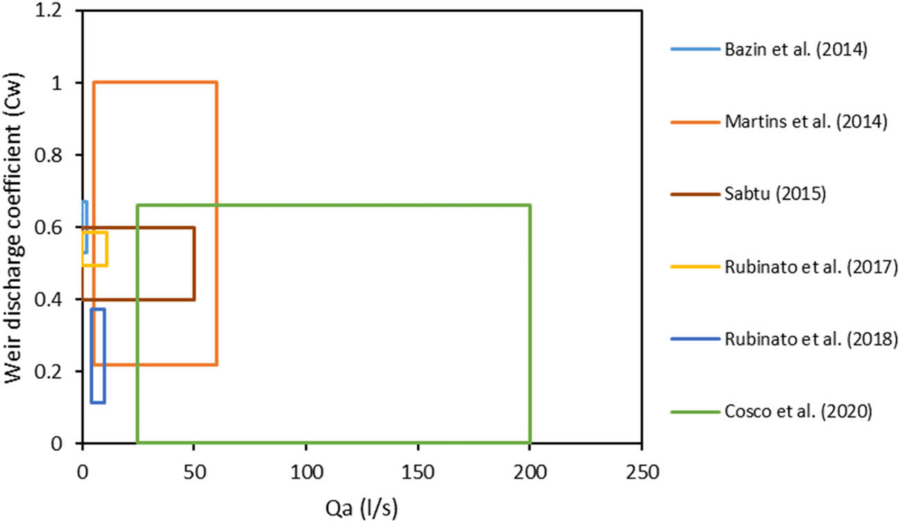
The range of weir (C w) and orifice (C o) discharge coefficients with the approaching flow (Q a) reported in previous studies are plotted in Figures 7 and 8, respectively. The weir discharge coefficient under supercritical flow was investigated in the study of Martins et al. [36] and Cosco et al. [34] for rectangular inlets without and with grates, respectively. Figure 7 shows that the weir discharge coefficient was in the range of 0.22–1 and 0.004–0.66 for inlets without and with grates, respectively. Therefore, the range of 0.22 < C w < 0.66 can be considered for grated and non-grated rectangular inlets under supercritical flow. On the other hand, the range of weir discharge coefficients under subcritical flow was in the range of 0.53 < C w < 0.67 for non-grated rectangular inlets and in the range of 0.4–0.6 for grated rectangular inlets as reported by Bazin et al. [35] and Sabtu [41], respectively. Based on that, a weir discharge coefficient in the range of 0.53 < C w < 0.6 can be adopted for the cases of grated and non-grated rectangular inlets under subcritical flow. The larger margin of the weir coefficient (0.4 < C w < 0.6) under supercritical flow compared to subcritical flow (0.53 < C w < 0.67) with low flow velocity is attributed to the larger influence of flow velocity on the hydraulic behavior of drainage systems under supercritical flow which can alter the inlet efficiency and discharge rates significantly. On the other hand, the flow interception shows a more stable behavior under subcritical flow characterized by higher water depths and lower flow velocities.
Relationship of the suggested range of weir discharge coefficients vs approaching flow.

Relationship of the suggested range of orifice discharge coefficients vs approaching flow.
Based on the study of Martins et al. [36] and Cosco et al. [34], it is recommended to use an orifice discharge coefficient of 1.67–2.68 for rectangular non-grated inlets and 0.03–0.47 for rectangular grated inlets under supercritical flow condition. Therefore, the orifice discharge coefficient of the non-grated rectangular inlet is found to be over 3.5 folds higher than that of the grated rectangular inlet. The orifice discharge coefficient superiority for inlets with no grate is due to the hydraulic jump in the case of surcharge grated inlets when the water splashes on the grated bars and consequently, larger energy loss and lower inlet surcharge rate. This hydraulic jump head loss is more pronounced in the case of supercritical flow characterized by larger flow velocity. For rectangular grated inlets under subcritical flow, Bazin et al. [35] reported that the orifice discharge coefficient (C o) is in the range of 0.39–0.46, whereas Sabtu [41] reported that the C o varies between 0.4 and 0.5 (Figure 8). Consequently, an orifice discharge coefficient in the range of 0.4–0.46 is recommended for rectangular grated inlets under subcritical flow. In the full-scale studies conducted by Gómez et al. [39], Tellez-Alvarez et al. [42], and Zambrano et al. [40], rectangular grate inlets were tested under surcharge conditions without mentioning the flow type (whether subcritical or supercritical). Beg et al. [53] carried out a similar full-scale study on rectangular inlets but with no lid cover. The orifice discharge coefficients of the studies of Beg et al. [53], Gómez et al. [39], Tellez-Alvarez et al. [42], and Zambrano et al. [40] were in the range of 0.677–0.82, 0.13–0.41, 0.14–0.41, and 0.07–0.39, respectively. Therefore, when the Froude number is unknown, the suggested orifice discharge coefficient is in the range of 0.14–0.39 and 0.677–0.82 for rectangular inlets with and without grates, respectively.
Finally, Rubinato et al. [37] tested a non-grated circular inlet under subcritical flow with a Froude number of 0.151–0.691. Similarly, Rubinato et al. [38] tested ten circular grated inlets under subcritical flow with a Froude number of 0.495–0.612. Figure 7 shows that under similar hydraulic conditions, it is recommended to use a weir discharge coefficient (C w) in the range of 0.493–0.587 and 0.115–0.372 for circular inlets without and with grate, respectively. Similarly, an orifice discharge coefficient (C o) in the range of 0.159–0.174 and 0.349–2.038 can be adopted for circular inlets without and with grate, respectively as shown in Figure 8.
2.2 Relationship between discharge coefficients and Froude number
Cosco et al. [34] tested three rectangular grated inlets (Barcelona-1, E-25, and Meridiana) under supercritical flow and formulated power functions to correlate the weir/orifice discharge coefficients (C w/C o) with the Froude number (Fr) as shown in Table 3. The graphs of the experimental weir and orifice discharge coefficients vs the Froude number (Fr) are plotted using the formulae reported by Martins et al. [36], Cosco et al. [34], Cárdenas-Quintero and Carvajal-Serna [46], and Zhuk et al. [55] as shown in Figure 9. The experimental and numerical orifice discharge coefficients of Martins et al. [36] exhibited high agreement showing the validity of numerical software (OpenFOAM) in simulating the hydraulic behavior of dual drainage systems accurately. Therefore, only the experimental results of the latter study are plotted in Figure 9. Graphically, the weir and orifice discharge coefficients of the three inlets investigated by Cosco et al. [34] showed a negative correlation with the Froude number (Fr). This agrees with the reported results of studies which show that weir and orifice discharge coefficients decrease at higher Froude number [48,75]. For instance, Figure 9 shows that at high flow velocity with Froude number Fr = 14, the weir and orifice discharge coefficients of inlet Barcelona-1 were as low as 0.004 and 0.03, respectively. As the Froude number increases, the flow is characterized by higher flow velocity, and therefore, the flow overpasses the inlet and splashes over its grate bars, and consequently, larger head loss, lower inlet discharge, lower efficiency, and lower discharge coefficients were reported. Moreover, the water films developed on the inlet surface are more intense under larger flow velocities, and therefore, lower discharge capacity. The water film over the inlet is reported to reduce the inlet efficiency significantly especially for inlets with short lengths where the water film may cover over 50% of the inlet length reducing its frontal and lateral interceptions as reported by Kim et al. [65]. In the study by Cosco et al. [34], the weir and orifice discharge coefficients showed a significant decline between Fr = 1 and Fr = 2, and thereafter, they decreased gradually with the Froude number increase. Similarly, the weir discharge coefficient of the non-grated inlet (0.6 × 0.3 m2) tested by Martins et al. [36] dropped significantly from C w = 0.99 at Fr = 1.42 to C w = 0.22 at Fr = 1.57. On the other hand, its orifice discharge coefficient increased sharply from 1.67 to 2.68 when the Froude number increased from 1.42 to 1.46 and dropped significantly beyond Fr = 1.46. This behavior can be due to the efficiency increasing to reach its optimum at Fr = 1.46 before it starts to drop with the Froude number increase.
Power correlation between the discharge coefficients and Froude number
| Reference | Grate | L × W (m2) | C w | C o |
|---|---|---|---|---|
| Cosco et al. [34] | Barcelona-1 | 0.745 × 0.26 |
|
|
| E-25 | 0.64 × 0.3 |
|
|
|
| Meridiana | 0.8 × 0.3 |
|
|
|
| Cárdenas-Quintero and Carvajal-Serna [46] | Dalian 4 | 0.549 × 0.338 |
|
NA |
| Dalian 5 | 0.461 × 0.21 |
|
NA | |
| Dalian 6 | 0.435 × 0.238 |
|
NA | |
| Zhuk et al. [55] | Inlet 1 | 0.245 × 0.245 |
|
|
| Inlet 2 | 0.325 × 0.325 |
|

Discharge coefficient vs Froude number for (a) weir flow and (b) orifice flow.
The grate inlet E-25 studied by Cosco et al. [34] and the non-grated gully of Martins et al. [36] have similar inlet dimensions of 0.64 × 0.3 m2 and 0.6 × 0.3 m2, respectively. However, the void area of the non-grated gully is 0.18 m2 which is 2.2 times higher than the effective void area of E-25 (0.0808 m2). Initially, the weir discharge coefficient of the non-grated gully was quite higher than E-25 until Fr = 1.55 where it dropped below the E-25 curve as shown in Figure 9(a). This behavior change may be attributed to the larger perimeter involved in the flow interception at higher Froude numbers and consequently, higher weir discharge coefficient. For instance, under weir flow, the inlet perimeter dominates and the effective perimeter of inlet E-25 is slightly higher than the non-grated gully of Martins et al. [36]. The larger effective perimeter can enhance the weir interception capacity of E-25 at higher Froude number flow with larger velocity where a larger portion of the grate surface/perimeter increases the frontal/lateral flow interception. Additionally, larger flow speed and Froude number are attributed to larger water film formed on the inlet and consequently, inlets with larger lengths surpass the performance of inlets with shorter lengths. On the other hand, the orifice effective area dominates under orifice discharge. Therefore, the orifice discharge coefficient of the non-grated gully of Martins et al. [36] was higher than its counterpart in inlet E-25 as shown in Figure 9(b). The inlet effective perimeter dominates for weir flow of free discharge inlets, whereas the inlet effective area governs the orifice flow of submerged inlets.
In the study by Sabtu [41], two full-scale gully inlets (gully A: 0.325 × 0.437 m2 and gully B: 0.4 × 0.432 m2) were tested experimentally under intermediate and terminal flow conditions. For the intermediate inlet, a part of the approaching flow (Q a) is captured/intercepted by the inlet (Q in) and the other part continues to the next inlet (Q b). Therefore, the approaching flow is equal to the sum of the intercepted flow, bypassed flow, and system loss (Q a = Q i + Q b + Q system loss). On the other hand, all the approaching flow is captured by the inlet and will not continue to the next inlet (sag inlets as an example) under terminal inlet conditions. The approaching flow is equal to the sum of the intercepted flow (Q i) and the system loss flow (Q ap = Q i + Q system loss). The findings of this study show that the discharge coefficients of the intermediate gully were lower than the terminal gully. This difference is due to the larger flow velocity and splash-over phenomenon on the grate bars that are more pronounced in the case of intermediate gully. This study formulated equations to correlate the discharge coefficient with the gully length, gully width, flow velocity, water depth, and Froude number. A second degree polynomial was used to represent the correlation between the discharge coefficient (C d) and the Froude number (Fr) for each gully under different flow conditions as shown in Table 4.
Equations of discharge coefficient (C d) vs Fr for gullies A and B [41]
| Flow condition | Gully | Equation |
|---|---|---|
| Terminal | A (0.325 × 0.437 m2) | Gully A: C d = −1.7282 Fr2 + 2.1827 Fr + 0.0149 |
| B (0.4 × 0.432 m2) | Gully B: C d = −0.5252 Fr2 + 1.4319 Fr + 0.1997 | |
| Intermediate | A (0.325 × 0.437 m2) | Gully A: C d = −11.087 Fr2 + 6.1246 Fr – 0.4554 |
| B (0.4 × 0.432 m2) | Gully B: C d = 3.616 Fr2 + 0.1917 Fr + 0.1413 |
2.3 Discussion and notes of inlet weir and orifice discharge coefficients
Previous research shows that as the water depth increases, the inlet intercepted flow changes from weir free discharge into orifice flow discharge [47,49,50]. During this transformation, the flow passes through a transitional stage with a transitional discharge coefficient of C t = 0.93 [47]. The inlet interception capacity at this critical stage is the minimum of the weir, transitional, and orifice discharge flow. Yet, studies on the discharge coefficients and the hydraulic characteristics of the transitional stage are still rare. This transitional stage is referred to as the partial weir and orifice stage in the research of Djordjević et al. [50]. The latter study tested terminal and intermediate circular reduced-scale gully from the UK. Several studies reported that as the water depth and flow rate increase under terminal conditions, flow transits from weir to orifice flow, and its discharge coefficients increase [41,50]. This is attributed to the positive correlation between the weir/orifice discharge equations and the water depth as well as the terminal inlet condition where all the flow will be intercepted at the inlet with no by-pass flow. Similarly, the discharge coefficients of level grate inlets are higher when compared to inclined or depressed inlets that encounter hydraulic jump and flow splash-over and consequently, experience more energy loss and lower intercepted discharge [52,60]. Overall, the graphical relation of the discharge coefficients with the approaching flow and with the Froude number shows a bell-shaped pattern. For instance, the discharge coefficient increases with the approaching flow to reach the inlet’s maximum efficiency and maximum discharge coefficients and starts to drop thereafter. From a hydraulic point of view, this graphical pattern represents the transformation of the flow from weir free flow at lower water depths to partially-weir-partially-orifice flow when the inlet is partially submerged at higher approaching flow, and finally, into orifice flow under larger approaching flow and water depth where the inlet is submerged in water. Similarly, as the Froude number increases, the flow changes from subcritical to supercritical flow characterized by shallow rapid flow which is more prone to the effect of flow splash-over the inlet which will reduce its interception capacity and discharge coefficients.
Previous studies show that the transversal slope has a positive correlation with the discharge coefficient as it increases the water transported from the road to the inlet, whereas the longitudinal slope shows a negative correlation as it increases the flow velocity, and therefore, the flow splash-over phenomenon resulting in reduced efficiency and discharge coefficients. Yet, the effect of the transversal slope on the discharge coefficients is more dominant. Even though previous studies reported that the frontal interception (inlet width) is the main mechanism of inlet flow interception compared to the side interception (inlet length), increasing the inlet width is not recommended on paved roads for safety reasons. Therefore, South Korea recently started using grated inlets of 150 cm length to cope with the climate changes that are expected to increase the rainfall intensities and durations in the future [65]. Moreover, the latter study showed that when the water splashes over the inlet, a water film is formed where it can cover up to 50% of the inlet in the case of inlets of short lengths. Even though previous studies showed that the effective perimeter governs the inlet weir flow and the effective area regulates the inlet orifice flow, it is important to note that the inlet effective perimeter has a more pronounced impact on the discharge equations than the inlet void area, particularly in cases where the perimeter is relatively large. Consequently, inlets with larger lengths are recommended for reducing the effect of the flow splash-over and the formed water film on the inlet efficiency and discharge capacity and to cope with climate change challenges on urban drainage systems.
The weir and orifice discharge coefficients showed a high correlation with the inlet effective perimeter and inlet effective area, respectively, under subcritical flow whereas, the weir and orifice discharge coefficients expressed a high correlation with the Froude number under supercritical flow. Under subcritical flow conditions characterized by slow deep flow, the inlet perimeter and effective area control the flow interception. On the other hand, the inlet perimeter and area become partially inefficient when they get covered by the water film produced from water splash-over when the water flow velocity reaches the critical flow and flow transits from subcritical to supercritical flow. Therefore, the inlet efficiency is controlled by the approaching flow, inlet perimeter, and inlet area under subcritical flow whereas, it is controlled by the Froude number under supercritical flow.
The discharge coefficients governing the flow of water through weirs and orifices are not static and they are influenced by the inlet type (circular, rectangular, grated, or non-grated), flow type (weir, transitional, or orifice), level of surcharge (low, intermediate, and high), and flow conditions (subcritical or supercritical flow) [35,53]. For instance, Tellez-Alvarez et al. [42] found that under surcharge conditions, there is an increase in the orifice discharge coefficient as the surcharge rate increases. The equations of the inlet discharge capacity depend on the flow condition (weir, transitional, or orifice). In urban drainage designs, it is crucial to determine the limits of each stage where the flow transforms from weir into transitional and then into orifice flow. In a previous study, findings showed that the flow is considered a weir flow when the ratio of the water depth to the short orifice dimension is below 0.5 and as an orifice flow when this ratio is higher than 0.5 [49]. Recently, Xia et al. [43] classified the subcritical flow of a rectangular inlet as a weir when the flow depth is below 45 mm high and as an orifice flow for water depth over 64 mm high. Yet, additional studies are required to determine the limits between weir and orifice flow and understand the hydraulic behavior at the transitional stage.
Several standards and manuals assume constant weir and orifice discharge coefficients. For example, the weir discharge coefficient is considered as C w = 3 in the manual by Brown et al. [70], DID [72], QUDM [58], and Texas [74]. Likewise, a constant orifice discharge coefficient of 0.6 [57–59] or 0.67 [70–74] is used in some references and numerical models. These orifice values obtained from tank emptying with no flow velocity, differ from those observed in surface flow runoff on streets [34]. Therefore, it is essential to consider the differences between these scenarios when evaluating the performance of orifices in the context of street drainage systems. Previous studies showed that assuming a constant weir or orifice discharge coefficient may significantly underestimate or overestimate the inlet’s actual discharge capacity and the hydraulic behavior of the urban drainage system. For instance, the orifice discharge coefficient of the rectangular grated inlets studied by Martins et al. [36] ranged between 1.67 and 2.68 which is 2.5–4 folds greater than adopting a constant orifice discharge coefficient of 0.67. Furthermore, the patterns and degrees of clogging significantly affect the discharge coefficients of drain inlets, with the clogging condition more dominant than the clogging pattern [54]. Thus, when selecting discharge coefficients for unclean drain inlets, it is essential to account for the potential clogging of the inlet specifically under overflow conditions.
The inlet discharge coefficients are influenced by the grate orientation where the fishbone curves experience higher orifice discharge coefficients than inlets with diagonal grates [36,64]. The weir and orifice discharge equations have been correlated using the power function with the inlet and flow parameters. Rubinato et al. [38] formulated the weir and orifice discharge coefficients of circular inlets under subcritical flow using power equations as a function of the inlet effective perimeter and the inlet effective area, respectively. Whereas, Martins et al. [36] and Cosco et al. [34] developed the power equations of the weir/orifice discharge coefficients for rectangular inlets under supercritical flow as a function of the flow depth and Froude number, respectively. On the other hand, Sabtu [41] used a second degree polynomial for correlating the discharge coefficients of grated rectangular gullies to the Froude number and reported that intermediate gullies showed lower discharge coefficients than the terminal gullies due to their vulnerability to flow splash-over under critical velocities. As the Froude number increases, the water velocity increases and the water film over the inlet is more intense with a more pronounced flow splash-over phenomenon. Consequently, under supercritical flow, it is recommended to increase road roughness to reduce the Froude number, and thereby, increase the inlet discharge coefficients and interception capacity.
The graphical analysis of the experimental data and equations reported in previous studies showed that the weir discharge coefficient of rectangular inlets under subcritical flow is in the range of 0.53–0.6 for grated and non-grated rectangular inlets and the orifice discharge coefficient is in the range of 0.4–0.46 for grated inlets. Moreover, the weir discharge coefficient is between 0.22 and 0.66 for grated and non-grated rectangular inlets under supercritical flow. On the other hand, the orifice discharge coefficient under supercritical flow is in the range of 0.03–0.47 and 1.67–2.68 for grated and non-grated rectangular inlets, respectively. For rectangular inlets with unknown Froude number, the orifice discharge coefficient of grated and non-grated inlets is in the range of 0.14–0.39 and 0.677–0.82, respectively. Finally, circular grated inlets under subcritical flow have weir and orifice discharge coefficients of 0.115–0.372 and 0.349–2.038, respectively. However, circular non-grated inlets under subcritical flow have weir and orifice discharge coefficients in the range of 0.493–0.587 and 0.159–0.174, respectively.
3 Conclusion and perspectives
This review sums up the main methodologies and equations of determining the inlet weir and orifice discharge coefficients and analyzes the values and correlations reported in recent studies to reduce the weir/orifice discharge uncertainty and find the accurate weir/orifice discharge coefficients that can be selected based on the inlet parameters and flow conditions. The result analysis and comparison led to the following conclusions:
The curve of discharge coefficient vs approaching flow vs Froude number shows a bell-shaped trend where the discharge coefficients increase with the approaching flow/Froude number increase to reach a maximum and decline afterwards. As the approaching flow increases, the flow passes from weir flow free discharge to partial-weir-partial-orifice (transitional stage) when the inlet is partially submerged and into orifice flow when it is fully submerged in water. Similarly, as the Froude number increases, the flow changes from a subcritical flow (slow flow) into a supercritical flow (rapid shallow flow) when the flow velocity and depth exceed the critical values of the transitional stage where the flow reaches its splash-over velocity threshold and the inlet becomes more prone to the influence of the formed water film on its grate, and therefore, its efficiency and discharge coefficients drop afterwards.
The effect of the approaching flow on the inlet hydraulic characteristics is more influential under subcritical flow, whereas the Froude number effect is more pronounced under supercritical flow. Therefore, the discharge coefficient correlation with the approaching flow is suggested under subcritical flow. On the other hand, the discharge coefficient correlation with the Froude number is recommended under supercritical flow characterized by larger flow velocity with a more pronounced flow splash-over phenomenon and reduced inlet interception capacity.
For rectangular inlets under subcritical flow, the weirs and orifices discharge coefficients are between 0.53 and 0.6 (for grated and non-grated inlets), and between 0.4 and 0.46 (for grated inlets), respectively. For rectangular inlets under supercritical flow, the weir discharge coefficient of grated and non-grated inlets is in the range of 0.22–0.66. For rectangular inlets under supercritical flow, the orifice discharge coefficient of grated and non-grated inlets is in the range of 0.03–0.47 and 1.67–2.68, respectively.
For flow with an unknown Froude number, the orifice discharge coefficient of grated and non-grated inlets is in the range of 0.14–0.39 and 0.677–0.82, respectively.
For circular grated inlets under subcritical flow, the weir and orifice discharge coefficients are in the range of 0.115–0.372 and 0.349–2.038, respectively. Whereas, the weir and orifice discharge coefficients of non-grated circular inlets under subcritical flow are in the range of 0.493–0.587 and 0.159–0.174, respectively.
Additional studies on the hydraulic limits and parameters governing the transitional stage from weir to orifice flow and from subcritical to supercritical flow are essential for understanding the hydraulic interaction between the surface and subsurface drainage systems to improve inlet design guidelines and mitigate urban flooding hazards.
Additional research is recommended on the partially-weir-partially-orifice transitional stage and its characteristics (critical depth/critical flow velocity) to determine the equations of the ascending and descending curves of the discharge coefficient vs approaching flow and Froude number.
There is a need for studies on orifice discharge coefficient equations and values for non-grated inlets under subcritical flow. Similarly, further research is needed on the weir and orifice discharge coefficients of circular grated and non-grated inlets under supercritical flow conditions.
Additional research is required on the hydraulic interaction of rectangular and circular inlets and the effect of the inlet geometrical shape on its hydraulic behavior as well as the influence of the topographic location of the drain inlet (centered, curb side) on its hydraulic characteristics.
-
Funding information: The authors wish to express gratitude to the Ministry of Higher Education Malaysia for the financial support under Fundamental Research Grant Scheme with Project Code: FRGS/1/2021/WAB02/USM/03/2 for this study.
-
Conflict of interest: Authors declare no conflict of interest with anyone related to the subject of the manuscript or any competing interest.
-
Data availability statement: Most datasets generated and analyzed in this study are comprised in this submitted manuscript. The other datasets are available on a reasonable request from the corresponding author with the attached information.
References
[1] Miller JD, Hutchins M. The impacts of urbanisation and climate change on urban flooding and urban water quality: A review of the evidence concerning the United Kingdom. J Hydrol: Regional Stud. 2017;12:345–62. 10.1016/j.ejrh.2017.06.006.Search in Google Scholar
[2] Hammond MJ, Chen AS, Djordjević S, Butler D, Mark O. Urban flood impact assessment: A state-of-the-art review. Urban Water J. 2015;12(1):14–29. 10.1080/1573062X.2013.857421.Search in Google Scholar
[3] Kareem HH, Alkatib AA. Future short-term estimation of flowrate of the Euphrates river catchment located in Al-Najaf Governorate, Iraq through using weather data and statistical downscaling model. Open Eng. 2022;12(1):129–41. 10.1515/eng-2022-0027.Search in Google Scholar
[4] Dai S, Hou J, Jin S, Zhang K, Hou J, Liu G. Discharge coefficients formulae of grate inlets of complicated conditions for urban floods simulation and urban drainage systems design. J Hydrol. 2023;625:1–12. 10.1016/j.jhydrol.2023.130089.Search in Google Scholar
[5] Zhou Q, Leng G, Su J, Ren Y. Comparison of urbanization and climate change impacts on urban flood volumes: Importance of urban planning and drainage adaptation. Sci Total Environ. 2019;658:24–33. 10.1016/j.scitotenv.2018.12.184.Search in Google Scholar PubMed
[6] Wakif S, Sabtu N. The effect of depression for a terminal gully inlet. Int J Civ Eng Technol. 2018;9(7):1920–6.Search in Google Scholar
[7] Singh D, Kumar M. Effect of the inlet-to-outlet key width ratio of Piano Key Weir on its hydraulic behaviour. Flow Meas Instrum. 2023;91:1–9. 10.1016/j.flowmeasinst.2023.102342.Search in Google Scholar
[8] Dai S, Jin S, Qian C, Yang N, Ma Y, Liang C. Interception efficiency of grate inlets for sustainable urban drainage systems design under different road slopes and approaching discharges. Urban Water J. 2021;18(8):650–61. 10.1080/1573062X.2021.1925702.Search in Google Scholar
[9] Osman YZ. Monitoring the future behaviour of urban drainage system under climate change: a case study from north-western England. Open Eng. 2014;5(1):1–5. 10.1515/eng-2015-0003.Search in Google Scholar
[10] Gómez M, Russo B, (editor). Methodology to estimate hydraulic efficiency of drain inlets. Proceedings of the institution of civil engineers-water management. London: Thomas Telford Ltd.; 2011.10.1680/wama.900070Search in Google Scholar
[11] Smith MB. Comment on ‘Analysis and modeling of flooding in urban drainage systems’. J Hydrol. 2006;3(317):355–663.10.1016/j.jhydrol.2005.05.027Search in Google Scholar
[12] Palla A, Colli M, Candela A, Aronica G, Lanza L. Pluvial flooding in urban areas: The role of surface drainage efficiency. J Flood Risk Manag. 2018;11:663–76. 10.1111/jfr3.12246.Search in Google Scholar
[13] Conner NW. Design and capacity of gutter inlets. USA: North Carolina State College; 1945.Search in Google Scholar
[14] Bauer WJ, Woo D-C. Hydraulic design of depressed curb opening inlets. Highw Res Rec. 1964;58:61–80.Search in Google Scholar
[15] Forbes H. Capacity of lateral stormwater inlets. Civ Eng-Siviele Ingenieurswese. 1976;9:195–205.Search in Google Scholar
[16] Holley ER, Woodward C, Brigneti A, Ott C. Hydraulic characteristics of recessed curb inlets and bridge drains. Austin, Texas, USA: Center of Transportation Research - The University of Texas; 1992.Search in Google Scholar
[17] Hammons MA, Holley ER. Hydraulic characteristics of flush depressed curb inlets and bridge deck drains. Austin, Texas, USA: Center of Transportation Research - The University of Texas; 1995.Search in Google Scholar
[18] Davis AC, Jacob R, Ellett B, (editor). Factors influencing the efficiency of road drainage gratings. Proceedings of the Institution of Civil Engineers-Municipal Engineer. Thomas Telford-ICE Virtual Library; 1998.10.1680/imuen.1998.30443Search in Google Scholar
[19] McEnroe BM, Wade RP, Smith AK. Hydraulic performance of curb and gutter inlets. Lawrence, Kansas, USA: University of Kansas School of Engineering; 1999.Search in Google Scholar
[20] Lee JH, Bang KW. Characterization of urban stormwater runoff. Water Res. 2000;34(6):1773–80.10.1016/S0043-1354(99)00325-5Search in Google Scholar
[21] Wakif S, Sabtu N, editor. Comparison of Different Methodologies for Determining the Efficiency of Gully Inlets. AWAM International Conference on Civil Engineering. Penang, Malaysia: Springer Nature Switzerland; 2019.10.1007/978-3-030-32816-0_99Search in Google Scholar
[22] Chibane T, Paquier A, Benmamar S. Experimental study of the flow patterns in a street during drainage or overflow to or from drains. Urban Water J. 2021;18(7):544–57. 10.1080/1573062X.2021.1913612.Search in Google Scholar
[23] Al-Bedyry NK, Kadim MA, Hussein SH, Al-Khafaji ZS, Al-Husseinawi FN. Experimental establishing of moving hydraulic jump in a trapezoidal channel. Civ Eng J. 2023;9(4):873–81. 10.28991/CEJ-2023-09-04-08.Search in Google Scholar
[24] Aminoroayaie Yamini O, Mousavi SH, Kavianpour M, Safari Ghaleh R. Hydrodynamic performance and cavitation analysis in bottom outlets of dam using CFD modelling. Adv Civ Eng. 2021;2021:1–14. 10.1155/2021/5529792.Search in Google Scholar
[25] Zaiter A, Sabtu N, editor. Methodologies for estimating the hydraulic efficiency of non-surcharged clean grate inlets, clogged grate inlets and continuous transversal grate inlets. AWAM International Conference on Civil Engineering. Penang, Malaysia: Springer Nature Singapore; 2022.Search in Google Scholar
[26] Li X, Li Y, Zheng S, Chen G, Zhao P, Wang C. High efficiency integrated urban flood inundation simulation based on the urban hydrologic unit. J Hydrol. 2024;630:1–12. 10.1016/j.jhydrol.2024.130724.Search in Google Scholar
[27] Rubinato M, Martins R, Shucksmith J. Quantification of energy losses at a surcharging manhole. Urban Water J. 2018;15(3):234–41. 10.1080/1573062X.2018.1424217.Search in Google Scholar
[28] Zheng Z, Gao J, Ma Z, Wang Z, Yang X, Luo X, et al. Urban flooding in China: main causes and policy recommendations. Hydrol Process. 2016;30(7):1149–52. 10.1002/hyp.10717.Search in Google Scholar
[29] Jo JB, Kim JS, Yoon SE. Experimental estimation of the head loss coefficient at surcharged four-way junction manholes. Urban Water J. 2018;15(8):780–9. 10.1080/1573062X.2018.1547408.Search in Google Scholar
[30] Padulano R, Del Giudice G. Vertical drain and overflow pipes: literature review and new experimental data. J Irrig Drain Eng. 2018;144(6):1–12. 10.1061/(ASCE)IR.1943-4774.0001311.Search in Google Scholar
[31] Jang J-H, Chang T-H, Chen W-B. Effect of inlet modelling on surface drainage in coupled urban flood simulation. J Hydrol. 2018;562:168–80. 10.1016/j.jhydrol.2018.05.010.Search in Google Scholar
[32] Pour SH, Abd Wahab AK, Shahid S, Asaduzzaman M, Dewan A. Low impact development techniques to mitigate the impacts of climate-change-induced urban floods: Current trends, issues and challenges. Sustain Cities Soc. 2020;62:1–14. 10.1016/j.scs.2020.102373.Search in Google Scholar
[33] Cárdenas-Quintero M, Carvajal-Serna LF, Marbello-Pérez R. Two-dimensional hydro. Dyn Anal Surf Drain an urban road Dyna. 2019;86(211):102–11. 10.15446/dyna.v86n211.79524.Search in Google Scholar
[34] Cosco C, Gómez M, Russo B, Tellez-Alvarez J, Macchione F, Costabile P, et al. Discharge coefficients for specific grated inlets. Influence of the Froude number. Urban Water J. 2020;17(7):656–68. 10.1080/1573062X.2020.1811881.Search in Google Scholar
[35] Bazin P-H, Nakagawa H, Kawaike K, Paquier A, Mignot E. Modeling flow exchanges between a street and an underground drainage pipe during urban floods. J Hydraul Eng. 2014;140(10):1–10. 0.1061/(ASCE)HY.1943-7900.0000917.Search in Google Scholar
[36] Martins R, Leandro J, de Carvalho RF. Characterization of the hydraulic performance of a gully under drainage conditions. Water Sci Technol. 2014;69(12):2423–30. 10.2166/wst.2014.168.Search in Google Scholar PubMed
[37] Rubinato M, Martins R, Kesserwani G, Leandro J, Djordjević S, Shucksmith J. Experimental calibration and validation of sewer/surface flow exchange equations in steady and unsteady flow conditions. J Hydrol. 2017;552:421–32. 10.1016/j.jhydrol.2017.06.024.Search in Google Scholar
[38] Rubinato M, Lee S, Martins R, Shucksmith JD. Surface to sewer flow exchange through circular inlets during urban flood conditions. J Hydroinformatics. 2018;20(3):564–76. 10.2166/hydro.2018.127.Search in Google Scholar
[39] Gómez M, Russo B, Tellez-Alvarez J. Experimental investigation to estimate the discharge coefficient of a grate inlet under surcharge conditions. Urban Water J. 2019;16(2):85–91. 10.1080/1573062X.2019.1634107.Search in Google Scholar
[40] Zambrano MC, González HEM, Tequia WEA. Three-dimensional Numerical Evaluation of Hydraulic Efficiency and Discharge Coefficient in Grate Inlets. Environ Res, Eng Manag. 2022;78(4):121–36. 10.5755/j01.erem.78.4.31243.Search in Google Scholar
[41] Sabtu N. Hydraulic interaction between the above and below ground drainage systems via gully inlets [Doctoral dissertation]. University of Sheffield; 2015.Search in Google Scholar
[42] Tellez-Alvarez J, Gómez M, Russo B, Amezaga-Kutija M. Numerical and experimental approaches to estimate discharge coefficients and energy loss coefficients in pressurized grated inlets. Hydrology. 2021;8(4):1–16. 10.3390/hydrology8040162.Search in Google Scholar
[43] Xia J, Dong B, Zhou M, Ahmadian R, Falconer RA, Li Q, et al. A unified formula for discharge capacity of street inlets for urban flood management. J Hydrol. 2022;609:1–7. 10.1016/j.jhydrol.2022.127667.Search in Google Scholar
[44] Cárdenas-Quintero M, Carvajal-Serna F. Review of the hydraulic capacity of urban grate inlet: a global and Latin American perspective. Water Sci Technol. 2021;83(11):2575–96.10.2166/wst.2021.151Search in Google Scholar PubMed
[45] Russo B, Valentín MG, Tellez-Álvarez J. The relevance of grated inlets within surface drainage systems in the field of urban flood resilience. A review of several experimental and numerical simulation approaches. Sustainability. 2021;13(13):1–13. 10.3390/su13137189.Search in Google Scholar
[46] Cárdenas-Quintero M, Carvajal-Serna F. Hydraulic capacity of a grate inlet in supercritical flow: weir equation. Urban Water J. 2023;20(6):763–8. 10.1080/1573062X.2023.2209066.Search in Google Scholar
[47] Guo JC, MacKenzie KA, Mommandi A. Design of street sump inlet. J Hydraul Eng. 2009;135(11):1000–4. 10.1061/(ASCE)HY.1943-7900.0000094.Search in Google Scholar
[48] Mustaffa Z, Rajaratnam N, Zhu DZ. An experimental study of flow into orifices and grating inlets on streets. Can J Civ Eng. 2006;33(7):837–45. 10.1139/L06-031.Search in Google Scholar
[49] Lee S, Nakagawa H, Kawaike K, Zhang H. Study on inlet discharge coefficient through the different shapes of storm drains for urban inundation analysis. J Japan Soc Civil EngSer B1 (Hydraul Eng). 2012;68(4):31–6.10.2208/jscejhe.68.I_31Search in Google Scholar
[50] Djordjević S, Saul AJ, Tabor GR, Blanksby J, Galambos I, Sabtu N, et al. Experimental and numerical investigation of interactions between above and below ground drainage systems. Water Sci Technol. 2013;67(3):535–42. 10.2166/wst.2012.570.Search in Google Scholar PubMed
[51] Sezenöz B Numerical modelling of continuous transverse grates for hydraulic efficiency: Middle East Technical University; 2014.Search in Google Scholar
[52] Guo JC, MacKenzie KA, Mommandi A. Flow interception capacity of inclined grate. J Irrig Drain Eng. 2016;142(4):1–5. 10.1061/(ASCE)IR.1943-4774.0000999.Search in Google Scholar
[53] Beg MNA, Carvalho RF, Leandro J. Effect of surcharge on gully-manhole flow. J Hydro-Environ Res. 2018;19:224–36. 10.1016/j.jher.2017.08.003.Search in Google Scholar
[54] Hao X, Mu J, Shi H. Experimental study on the inlet discharge capacity under different clogging conditions. Water. 2021;13(6):1–12. 10.3390/w13060826.Search in Google Scholar
[55] Zhuk V, Matlai I, Zavoiko B, Popadiuk I, Pavlyshyn V, Mysak I, et al. Experimental hydraulic parameters of drainage grate inlets with a horizontal outflow in the broad-crested weir mode. Water Sci & Technol. 2023;88(3):738–50. 10.2166/wst.2023.234.Search in Google Scholar PubMed
[56] Neenah. Manual of Engineering Tools & Calculations. United States of America. Retrieved from: https://www.nfco.com/engineeringtools-calculators/. 2018.Search in Google Scholar
[57] WVDOH. West Virginia Department of Transportation Division of Highway, Drainage Manual with Addendum 1 and 2. 3rd edn. 2007.Search in Google Scholar
[58] QUDM. Queensland Urban Drainage Manual. 4th edn. Institute of Public Works Engineering Australasia; 2017.Search in Google Scholar
[59] Australia. Stormwater management manual for Western Australia. Department of Water, Government of Western Australia; 2004.Search in Google Scholar
[60] Wakif S, Sabtu N. Hydraulic performance of vertically depressed and non-depressed grate. Urban Water J. 2019;16(8):554–63. 10.1080/1573062X.2019.1694693.Search in Google Scholar
[61] Gómez M, Recasens J, Russo B, Martínez-Gomariz E. Assessment of inlet efficiency through a 3D simulation: numerical and experimental comparison. Water Sci Technol. 2016;74(8):1926–35. 10.2166/wst.2016.326.Search in Google Scholar PubMed
[62] Tellez-Alvarez J, Gómez M, Russo B. Quantification of energy loss in two grated inlets under pressure. Water. 2020;12(6):1601–15. 10.3390/w12061601.Search in Google Scholar
[63] Rubinato M, Lee S, Kesserwani G, Shucksmith J, (editors). Experimental and numerical investigation of water depths around a manhole under drainage conditions. Proceeding of 12th International Conference on Hydroinformatics-Smart water for the future. Sheffield; 2016.Search in Google Scholar
[64] Fathy I, Abdel-Aal GM, Fahmy MR, Fathy A, Zeleňáková M, Abd-Elhamid HF, et al. Effect of changing the shape and size of inlet area of grates on the hydraulic efficiency of urban rainstorm drainage systems. Water. 2022;14(16):1–14. 10.3390/w14162541.Search in Google Scholar
[65] Kim JS, Kwak CJ, Jo JB. Enhanced method for estimation of flow intercepted by drainage grate inlets on roads. J Environ Manag. 2021;279:1–9. 10.1016/j.jenvman.2020.111546.Search in Google Scholar PubMed
[66] Veerappan R, Le J, editors. Hydraulic efficiency of road drainage inlets for storm drainage system under clogging effect. 5th International Conference on Flood Risk Management and Response. San Servolo, Italy: WIT Press; 2016.10.2495/UW160241Search in Google Scholar
[67] Russo B, Gómez M, Tellez J. Methodology to estimate the hydraulic efficiency of nontested continuous transverse grates. J Irrig Drain Eng. 2013;139(10):864–71. 10.1061/(ASCE)IR.1943-4774.0000625.Search in Google Scholar
[68] Despotovic J, Plavsic J, Stefanovic N, Pavlovic D. Inefficiency of storm water inlets as a source of urban floods. Water Sci Technol. 2005;51(2):139–45.10.2166/wst.2005.0041Search in Google Scholar
[69] Ekmekcioğlu Ö, Başakın EE, Özger M. Developing meta-heuristic optimization based ensemble machine learning algorithms for hydraulic efficiency assessment of storm water grate inlets. Urban Water J. 2022;19(10):1093–108. 10.1080/1573062X.2022.2134806.Search in Google Scholar
[70] Brown S, Schall J, Morris J, Doherty C, Stein S, Warner J. Urban drainage design manual. Hydraul Eng Circ. 2009;22:1–478.Search in Google Scholar
[71] Dakota. South Dakota Drainage Manual. Chapter 12 Storm Drainage Systems. Dakota, USA: South Dakota Department of Transportation; 2011.Search in Google Scholar
[72] DID. Urban stormwater management manual for Malaysia (MSMA). Government of Malaysia Department of Irrigation and Drainage. 2nd edn. Kuala Lumpur, Malaysia: Department of Irrigation and Drainage; 2012.Search in Google Scholar
[73] USDCM. Urban storm drainage criteria manual: management, hydrology, and hydraulics. Urban Drain Flood Control District. vol. 1, 2016.Search in Google Scholar
[74] Texas. Hydraulic Design Manual, Texas Department of Transportation. 2019.Search in Google Scholar
[75] Wu C, Yu JT, Wong AS, Li CW. Hydraulic interception efficiency of gully gratings on steep roads. HKIE Trans. 2015;22(3):192–8. 10.1080/1023697X.2015.1061704.Search in Google Scholar
© 2024 the author(s), published by De Gruyter
This work is licensed under the Creative Commons Attribution 4.0 International License.
Articles in the same Issue
- Regular Articles
- Methodology of automated quality management
- Influence of vibratory conveyor design parameters on the trough motion and the self-synchronization of inertial vibrators
- Application of finite element method in industrial design, example of an electric motorcycle design project
- Correlative evaluation of the corrosion resilience and passivation properties of zinc and aluminum alloys in neutral chloride and acid-chloride solutions
- Will COVID “encourage” B2B and data exchange engineering in logistic firms?
- Influence of unsupported sleepers on flange climb derailment of two freight wagons
- A hybrid detection algorithm for 5G OTFS waveform for 64 and 256 QAM with Rayleigh and Rician channels
- Effect of short heat treatment on mechanical properties and shape memory properties of Cu–Al–Ni shape memory alloy
- Exploring the potential of ammonia and hydrogen as alternative fuels for transportation
- Impact of insulation on energy consumption and CO2 emissions in high-rise commercial buildings at various climate zones
- Advanced autopilot design with extremum-seeking control for aircraft control
- Adaptive multidimensional trust-based recommendation model for peer to peer applications
- Effects of CFRP sheets on the flexural behavior of high-strength concrete beam
- Enhancing urban sustainability through industrial synergy: A multidisciplinary framework for integrating sustainable industrial practices within urban settings – The case of Hamadan industrial city
- Advanced vibrant controller results of an energetic framework structure
- Application of the Taguchi method and RSM for process parameter optimization in AWSJ machining of CFRP composite-based orthopedic implants
- Improved correlation of soil modulus with SPT N values
- Technologies for high-temperature batch annealing of grain-oriented electrical steel: An overview
- Assessing the need for the adoption of digitalization in Indian small and medium enterprises
- A non-ideal hybridization issue for vertical TFET-based dielectric-modulated biosensor
- Optimizing data retrieval for enhanced data integrity verification in cloud environments
- Performance analysis of nonlinear crosstalk of WDM systems using modulation schemes criteria
- Nonlinear finite-element analysis of RC beams with various opening near supports
- Thermal analysis of Fe3O4–Cu/water over a cone: a fractional Maxwell model
- Radial–axial runner blade design using the coordinate slice technique
- Theoretical and experimental comparison between straight and curved continuous box girders
- Effect of the reinforcement ratio on the mechanical behaviour of textile-reinforced concrete composite: Experiment and numerical modeling
- Experimental and numerical investigation on composite beam–column joint connection behavior using different types of connection schemes
- Enhanced performance and robustness in anti-lock brake systems using barrier function-based integral sliding mode control
- Evaluation of the creep strength of samples produced by fused deposition modeling
- A combined feedforward-feedback controller design for nonlinear systems
- Effect of adjacent structures on footing settlement for different multi-building arrangements
- Analyzing the impact of curved tracks on wheel flange thickness reduction in railway systems
- Review Articles
- Mechanical and smart properties of cement nanocomposites containing nanomaterials: A brief review
- Applications of nanotechnology and nanoproduction techniques
- Relationship between indoor environmental quality and guests’ comfort and satisfaction at green hotels: A comprehensive review
- Communication
- Techniques to mitigate the admission of radon inside buildings
- Erratum
- Erratum to “Effect of short heat treatment on mechanical properties and shape memory properties of Cu–Al–Ni shape memory alloy”
- Special Issue: AESMT-3 - Part II
- Integrated fuzzy logic and multicriteria decision model methods for selecting suitable sites for wastewater treatment plant: A case study in the center of Basrah, Iraq
- Physical and mechanical response of porous metals composites with nano-natural additives
- Special Issue: AESMT-4 - Part II
- New recycling method of lubricant oil and the effect on the viscosity and viscous shear as an environmentally friendly
- Identify the effect of Fe2O3 nanoparticles on mechanical and microstructural characteristics of aluminum matrix composite produced by powder metallurgy technique
- Static behavior of piled raft foundation in clay
- Ultra-low-power CMOS ring oscillator with minimum power consumption of 2.9 pW using low-voltage biasing technique
- Using ANN for well type identifying and increasing production from Sa’di formation of Halfaya oil field – Iraq
- Optimizing the performance of concrete tiles using nano-papyrus and carbon fibers
- Special Issue: AESMT-5 - Part II
- Comparative the effect of distribution transformer coil shape on electromagnetic forces and their distribution using the FEM
- The complex of Weyl module in free characteristic in the event of a partition (7,5,3)
- Restrained captive domination number
- Experimental study of improving hot mix asphalt reinforced with carbon fibers
- Asphalt binder modified with recycled tyre rubber
- Thermal performance of radiant floor cooling with phase change material for energy-efficient buildings
- Surveying the prediction of risks in cryptocurrency investments using recurrent neural networks
- A deep reinforcement learning framework to modify LQR for an active vibration control applied to 2D building models
- Evaluation of mechanically stabilized earth retaining walls for different soil–structure interaction methods: A review
- Assessment of heat transfer in a triangular duct with different configurations of ribs using computational fluid dynamics
- Sulfate removal from wastewater by using waste material as an adsorbent
- Experimental investigation on strengthening lap joints subjected to bending in glulam timber beams using CFRP sheets
- A study of the vibrations of a rotor bearing suspended by a hybrid spring system of shape memory alloys
- Stability analysis of Hub dam under rapid drawdown
- Developing ANFIS-FMEA model for assessment and prioritization of potential trouble factors in Iraqi building projects
- Numerical and experimental comparison study of piled raft foundation
- Effect of asphalt modified with waste engine oil on the durability properties of hot asphalt mixtures with reclaimed asphalt pavement
- Hydraulic model for flood inundation in Diyala River Basin using HEC-RAS, PMP, and neural network
- Numerical study on discharge capacity of piano key side weir with various ratios of the crest length to the width
- The optimal allocation of thyristor-controlled series compensators for enhancement HVAC transmission lines Iraqi super grid by using seeker optimization algorithm
- Numerical and experimental study of the impact on aerodynamic characteristics of the NACA0012 airfoil
- Effect of nano-TiO2 on physical and rheological properties of asphalt cement
- Performance evolution of novel palm leaf powder used for enhancing hot mix asphalt
- Performance analysis, evaluation, and improvement of selected unsignalized intersection using SIDRA software – Case study
- Flexural behavior of RC beams externally reinforced with CFRP composites using various strategies
- Influence of fiber types on the properties of the artificial cold-bonded lightweight aggregates
- Experimental investigation of RC beams strengthened with externally bonded BFRP composites
- Generalized RKM methods for solving fifth-order quasi-linear fractional partial differential equation
- An experimental and numerical study investigating sediment transport position in the bed of sewer pipes in Karbala
- Role of individual component failure in the performance of a 1-out-of-3 cold standby system: A Markov model approach
- Implementation for the cases (5, 4) and (5, 4)/(2, 0)
- Center group actions and related concepts
- Experimental investigation of the effect of horizontal construction joints on the behavior of deep beams
- Deletion of a vertex in even sum domination
- Deep learning techniques in concrete powder mix designing
- Effect of loading type in concrete deep beam with strut reinforcement
- Studying the effect of using CFRP warping on strength of husk rice concrete columns
- Parametric analysis of the influence of climatic factors on the formation of traditional buildings in the city of Al Najaf
- Suitability location for landfill using a fuzzy-GIS model: A case study in Hillah, Iraq
- Hybrid approach for cost estimation of sustainable building projects using artificial neural networks
- Assessment of indirect tensile stress and tensile–strength ratio and creep compliance in HMA mixes with micro-silica and PMB
- Density functional theory to study stopping power of proton in water, lung, bladder, and intestine
- A review of single flow, flow boiling, and coating microchannel studies
- Effect of GFRP bar length on the flexural behavior of hybrid concrete beams strengthened with NSM bars
- Exploring the impact of parameters on flow boiling heat transfer in microchannels and coated microtubes: A comprehensive review
- Crumb rubber modification for enhanced rutting resistance in asphalt mixtures
- Special Issue: AESMT-6
- Design of a new sorting colors system based on PLC, TIA portal, and factory I/O programs
- Forecasting empirical formula for suspended sediment load prediction at upstream of Al-Kufa barrage, Kufa City, Iraq
- Optimization and characterization of sustainable geopolymer mortars based on palygorskite clay, water glass, and sodium hydroxide
- Sediment transport modelling upstream of Al Kufa Barrage
- Study of energy loss, range, and stopping time for proton in germanium and copper materials
- Effect of internal and external recycle ratios on the nutrient removal efficiency of anaerobic/anoxic/oxic (VIP) wastewater treatment plant
- Enhancing structural behaviour of polypropylene fibre concrete columns longitudinally reinforced with fibreglass bars
- Sustainable road paving: Enhancing concrete paver blocks with zeolite-enhanced cement
- Evaluation of the operational performance of Karbala waste water treatment plant under variable flow using GPS-X model
- Design and simulation of photonic crystal fiber for highly sensitive chemical sensing applications
- Optimization and design of a new column sequencing for crude oil distillation at Basrah refinery
- Inductive 3D numerical modelling of the tibia bone using MRI to examine von Mises stress and overall deformation
- An image encryption method based on modified elliptic curve Diffie-Hellman key exchange protocol and Hill Cipher
- Experimental investigation of generating superheated steam using a parabolic dish with a cylindrical cavity receiver: A case study
- Effect of surface roughness on the interface behavior of clayey soils
- Investigated of the optical properties for SiO2 by using Lorentz model
- Measurements of induced vibrations due to steel pipe pile driving in Al-Fao soil: Effect of partial end closure
- Experimental and numerical studies of ballistic resistance of hybrid sandwich composite body armor
- Evaluation of clay layer presence on shallow foundation settlement in dry sand under an earthquake
- Optimal design of mechanical performances of asphalt mixtures comprising nano-clay additives
- Advancing seismic performance: Isolators, TMDs, and multi-level strategies in reinforced concrete buildings
- Predicted evaporation in Basrah using artificial neural networks
- Energy management system for a small town to enhance quality of life
- Numerical study on entropy minimization in pipes with helical airfoil and CuO nanoparticle integration
- Equations and methodologies of inlet drainage system discharge coefficients: A review
- Thermal buckling analysis for hybrid and composite laminated plate by using new displacement function
- Investigation into the mechanical and thermal properties of lightweight mortar using commercial beads or recycled expanded polystyrene
- Experimental and theoretical analysis of single-jet column and concrete column using double-jet grouting technique applied at Al-Rashdia site
- The impact of incorporating waste materials on the mechanical and physical characteristics of tile adhesive materials
- Seismic resilience: Innovations in structural engineering for earthquake-prone areas
- Automatic human identification using fingerprint images based on Gabor filter and SIFT features fusion
- Performance of GRKM-method for solving classes of ordinary and partial differential equations of sixth-orders
- Visible light-boosted photodegradation activity of Ag–AgVO3/Zn0.5Mn0.5Fe2O4 supported heterojunctions for effective degradation of organic contaminates
- Production of sustainable concrete with treated cement kiln dust and iron slag waste aggregate
- Key effects on the structural behavior of fiber-reinforced lightweight concrete-ribbed slabs: A review
- A comparative analysis of the energy dissipation efficiency of various piano key weir types
- Special Issue: Transport 2022 - Part II
- Variability in road surface temperature in urban road network – A case study making use of mobile measurements
- Special Issue: BCEE5-2023
- Evaluation of reclaimed asphalt mixtures rejuvenated with waste engine oil to resist rutting deformation
- Assessment of potential resistance to moisture damage and fatigue cracks of asphalt mixture modified with ground granulated blast furnace slag
- Investigating seismic response in adjacent structures: A study on the impact of buildings’ orientation and distance considering soil–structure interaction
- Improvement of porosity of mortar using polyethylene glycol pre-polymer-impregnated mortar
- Three-dimensional analysis of steel beam-column bolted connections
- Assessment of agricultural drought in Iraq employing Landsat and MODIS imagery
- Performance evaluation of grouted porous asphalt concrete
- Optimization of local modified metakaolin-based geopolymer concrete by Taguchi method
- Effect of waste tire products on some characteristics of roller-compacted concrete
- Studying the lateral displacement of retaining wall supporting sandy soil under dynamic loads
- Seismic performance evaluation of concrete buttress dram (Dynamic linear analysis)
- Behavior of soil reinforced with micropiles
- Possibility of production high strength lightweight concrete containing organic waste aggregate and recycled steel fibers
- An investigation of self-sensing and mechanical properties of smart engineered cementitious composites reinforced with functional materials
- Forecasting changes in precipitation and temperatures of a regional watershed in Northern Iraq using LARS-WG model
- Experimental investigation of dynamic soil properties for modeling energy-absorbing layers
- Numerical investigation of the effect of longitudinal steel reinforcement ratio on the ductility of concrete beams
- An experimental study on the tensile properties of reinforced asphalt pavement
- Self-sensing behavior of hot asphalt mixture with steel fiber-based additive
- Behavior of ultra-high-performance concrete deep beams reinforced by basalt fibers
- Optimizing asphalt binder performance with various PET types
- Investigation of the hydraulic characteristics and homogeneity of the microstructure of the air voids in the sustainable rigid pavement
- Enhanced biogas production from municipal solid waste via digestion with cow manure: A case study
- Special Issue: AESMT-7 - Part I
- Preparation and investigation of cobalt nanoparticles by laser ablation: Structure, linear, and nonlinear optical properties
- Seismic analysis of RC building with plan irregularity in Baghdad/Iraq to obtain the optimal behavior
- The effect of urban environment on large-scale path loss model’s main parameters for mmWave 5G mobile network in Iraq
- Formatting a questionnaire for the quality control of river bank roads
- Vibration suppression of smart composite beam using model predictive controller
- Machine learning-based compressive strength estimation in nanomaterial-modified lightweight concrete
- In-depth analysis of critical factors affecting Iraqi construction projects performance
- Behavior of container berth structure under the influence of environmental and operational loads
- Energy absorption and impact response of ballistic resistance laminate
- Effect of water-absorbent polymer balls in internal curing on punching shear behavior of bubble slabs
- Effect of surface roughness on interface shear strength parameters of sandy soils
- Evaluating the interaction for embedded H-steel section in normal concrete under monotonic and repeated loads
- Estimation of the settlement of pile head using ANN and multivariate linear regression based on the results of load transfer method
- Enhancing communication: Deep learning for Arabic sign language translation
- A review of recent studies of both heat pipe and evaporative cooling in passive heat recovery
- Effect of nano-silica on the mechanical properties of LWC
- An experimental study of some mechanical properties and absorption for polymer-modified cement mortar modified with superplasticizer
- Digital beamforming enhancement with LSTM-based deep learning for millimeter wave transmission
- Developing an efficient planning process for heritage buildings maintenance in Iraq
- Design and optimization of two-stage controller for three-phase multi-converter/multi-machine electric vehicle
- Evaluation of microstructure and mechanical properties of Al1050/Al2O3/Gr composite processed by forming operation ECAP
- Calculations of mass stopping power and range of protons in organic compounds (CH3OH, CH2O, and CO2) at energy range of 0.01–1,000 MeV
- Investigation of in vitro behavior of composite coating hydroxyapatite-nano silver on 316L stainless steel substrate by electrophoretic technic for biomedical tools
- A review: Enhancing tribological properties of journal bearings composite materials
- Improvements in the randomness and security of digital currency using the photon sponge hash function through Maiorana–McFarland S-box replacement
- Design a new scheme for image security using a deep learning technique of hierarchical parameters
- Special Issue: ICES 2023
- Comparative geotechnical analysis for ultimate bearing capacity of precast concrete piles using cone resistance measurements
- Visualizing sustainable rainwater harvesting: A case study of Karbala Province
- Geogrid reinforcement for improving bearing capacity and stability of square foundations
- Evaluation of the effluent concentrations of Karbala wastewater treatment plant using reliability analysis
- Adsorbent made with inexpensive, local resources
- Effect of drain pipes on seepage and slope stability through a zoned earth dam
- Sediment accumulation in an 8 inch sewer pipe for a sample of various particles obtained from the streets of Karbala city, Iraq
- Special Issue: IETAS 2024 - Part I
- Analyzing the impact of transfer learning on explanation accuracy in deep learning-based ECG recognition systems
- Effect of scale factor on the dynamic response of frame foundations
- Improving multi-object detection and tracking with deep learning, DeepSORT, and frame cancellation techniques
- The impact of using prestressed CFRP bars on the development of flexural strength
- Assessment of surface hardness and impact strength of denture base resins reinforced with silver–titanium dioxide and silver–zirconium dioxide nanoparticles: In vitro study
- A data augmentation approach to enhance breast cancer detection using generative adversarial and artificial neural networks
- Modification of the 5D Lorenz chaotic map with fuzzy numbers for video encryption in cloud computing
- Special Issue: 51st KKBN - Part I
- Evaluation of static bending caused damage of glass-fiber composite structure using terahertz inspection