Effect of the reinforcement ratio on the mechanical behaviour of textile-reinforced concrete composite: Experiment and numerical modeling
-
Xuan Bang Nguyen
 ,
Xuan Hong Vu
,
Xuan Hong Vu

Abstract
Over the past decade, the textile-reinforced concrete (TRC) composite was gradually used to replace the fibre-reinforced polymer in the strengthening or repairing of existing reinforced-concrete structures, thanks to many criteria of sustainable development. The reinforcement ratio of textiles within TRC composites emerges as a crucial factor significantly impacting their reinforcement effectiveness, altering the material’s mechanical behaviour and properties. This study presents both experimental and numerical findings concerning the tensile behaviour of carbon TRC composites, exploring reinforcement ratios ranging from 0.5 to 1.5%. As experimental results, the carbon TRC specimens exhibited a strain-hardening behaviour with the cracking phase. The ultimate strength improved by 95 and 146% compared to that of non-reinforced specimens, respectively, with the reinforcement ratio of 0.92 and 1.32%. As numerical results, the model reached the strain-hardening curve with three distinct phases when the reinforcement ratio was higher than a critical value (0.7%). The effect of reinforcement ratio ranging from 0.5 to 1.5% on the mechanical behaviour and properties of carbon TRC was also highlighted and analysed.
1 Introduction
Over the past decade, with the development of reinforcement methods, there has been a growing demand for strengthening or repairing existing reinforced-concrete (RC) structures that decreased their mechanical performance or cracked on their service life. This method ensures sustainability in the field of construction engineering [1,2]. Thanks to the development of material composite for construction, it could satisfy the high-quality requirement in mechanical properties. Among them, textile-reinforced concrete (TRC) and fibre-reinforced polymer (FRP) composites were commonly used for strengthening or repairing works [3,4]. The main difference between both composites is the nature of the matrix used, in which the polymer-based matrix is used for FRP, and the cement-based matrix is used for TRC. Then, the TRC satisfies several requirements of sustainable development than the FRP composite. Therefore, the TRC composite was gradually used to replace the FRP in the strengthening and/or repairing of RC members [5,6].
Literature showed several experimental and numerical studies on TRC composite at both material and structural scales. At the material scale, previous studies aimed to characterize the tensile or flexural behaviour and the mechanical properties of the TRC specimen. Nearly all findings demonstrate strain-hardening behaviour in TRC, marked by a cracking phase distinguished by stress drops. TRC’s behaviour could be divided into different phases depending on several factors belonging to the constitutive materials, interface bonding strength, and environmental conditions [7,8,9,10]. At structural scales, previous authors have performed structural tests on RC member strengthening with TRC composite withstands various loading cases. These studies aim to identify the reinforcement efficiency of TRC composite on the RC member compared with FRP. As a result, the TRC composite offered remarkable advantages for strengthening works in several special loading conditions such as earthquakes, elevated temperature, repetitive loading, etc. [11,12,13,14].
An important factor that could greatly influence the reinforcement efficiency of TRC composites on RC members is the number of textile layers used for strengthening. This factor involves the reinforcement ratio of textiles in the TRC composite leading to the change in the TRC’s mechanical behaviour and properties. Previous studies showed the enhancement of shear and flexural performances of RC member strengthening with TRC composite depending on the number of textile layers [15,16]. However, this evolution trend was not linear because it was still affected by the thickness of the cementitious matrix on TRC properties.
The effect of the number of textile layers and the cementitious matrix thickness on TRC’s mechanical behaviour and tensile properties has been investigated in previous studies [17,18,19]. Rambo et al. [20] have performed the tensile tests on basalt TRC specimens in which the number of basalt textile layers varied from 0, 1, 3, and 5 for a cementitious matrix plate with dimensions of 400 mm × 60 mm × 13 mm in length × width × thickness. The results showed that TRC’s mechanical behaviour was strongly influenced by the reinforcement ratio as well as, in comparison with the un-reinforced cementitious matrix, the TRC’s ultimate strength improved 1.01, 1.2, and 2.6 times, respectively, for 1, 3, and 5 reinforcement layers. The explanation for this effect could be understood by the effective thickness of the cementitious matrix for one reinforcement layer. It means that each layer of the cementitious matrix with an effective thickness together works with the reinforcement textile inside. This mechanism is essentially based on two main factors: the bonding strength of the textile/matrix interface and the shear stiffness of the cementitious matrix to transfer the internal force [21]. TRC composite has optimization characteristics if the matrix thickness per one textile layer is designed based on the effective thickness.
According to ACI Committee 549 [22] and ACI Committee 434 [23], the principle mechanical properties of TRC (or FRCM [fabric reinforced cementitious matrix]) used for flexural strengthening design are ultimate tensile strength (f fu) and strain (ε fu). Both values are highly influenced by the reinforcement ratio identified by the ratio of volume or cross-section between the reinforcement textile and the cementitious matrix. To identify ultimate values for all cases, it needs more experimental studies that have more cost and time. So, the numerical approach could be an alternative solution to solve this problem.
This article aims to elucidate the ultimate properties of TRC composite for strengthening design purposes. It presents both experimental and numerical findings regarding the mechanical behaviour of carbon TRC composite, spanning reinforcement ratios from 0.5 to 1.5%. In experimental work, the carbon TRC specimens with different numbers (0, 1, and 2 layers) of carbon textile layers were tested to identify the mechanical behaviour and tensile properties. For the numerical approach, a numerical model would be developed to predict the tensile behaviour of carbon TRC with different reinforcement ratios. From that, the effect of the reinforcement ratio on the carbon TRC’s mechanical behaviour and properties could be found and analysed.
2 Experimental works
2.1 Material used
2.1.1 Cementitious matrix
The cementitious matrix was formulated based on findings from previous studies [24,25] and subsequently tailored to suit laboratory conditions for fabricating TRC composite specimens. This matrix comprised synthetic silico-aluminous-calcium aggregate and calcium aluminate cement, designed for specialized applications. To ensure a low application thickness, superplasticizer and viscosity modifier were incorporated into the matrix composition. The mechanical properties of the matrix in its hardened state were evaluated through laboratory tests, including three-point bending and compressive strength assessments (Figure 1). Table 1 provides details of the mixture composition as well as the physical and mechanical properties of the cementitious matrix in this experimental investigation.
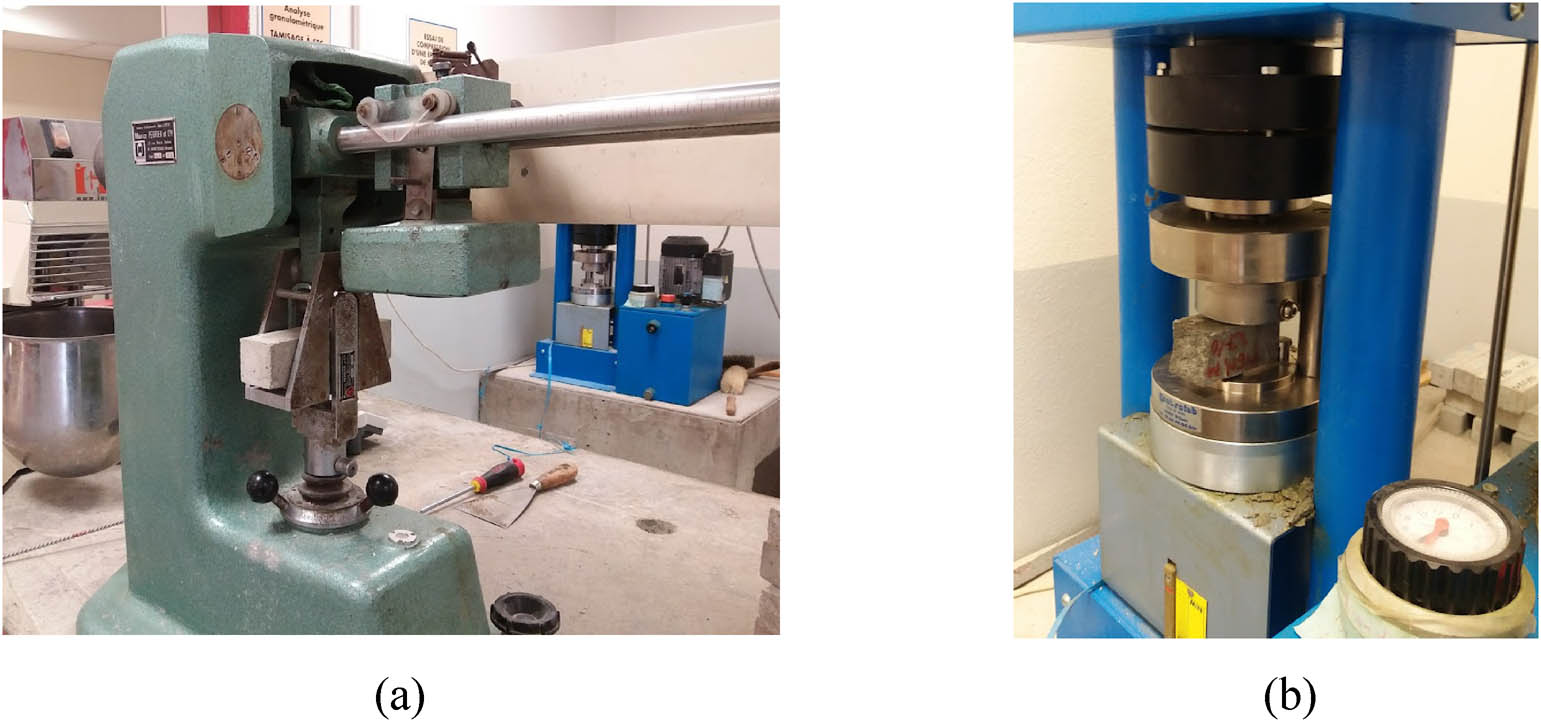
Images of tests for mechanical properties of the cementitious matrix. (a) Three-point bending test. (b) Compressive test.
Scientist information on the cementitious matrix
| Composition | Density (g/cm3) | Compressive strength after 28 days (MPa) | Flexural tensile strength after 28 days (MPa) | |
|---|---|---|---|---|
| Aggregate (kg/m3) | 1,676 | 2.53 | 58.1 | 12.5 |
| Cement (kg/m3) | 669 | |||
| Superplasticizer (kg/m3) | 4.34 | |||
| Viscosity modifier agent (VMA) (kg/m3) | 0.51 | |||
| Water (kg/m3) | 234.2 | |||
| Water/cement ratio | 0.35 | |||
2.1.2 Carbon textile
The carbon textile, depicted in Figure 2, comprises a bidirectional carbon grid with longitudinal and transverse dimensions of 17 mm × 17 mm. It boasts several advantages, including remarkable high tensile capacity (with an ultimate strength of 1,312 MPa and Young’s modulus of 144 GPa), high heat and corrosion resistance, low surface mass (density of 1.79 g/cm3), and a simple and flexible application for structural reinforcements, even with low thickness (such as underneath slabs). To enhance bonding strength with the cementitious matrix, the carbon fibre underwent treatment with amorphous silica. Each cross-section of the textile yarn (both weft and warp) measures 1.795 mm2. They consist of approximately 3,200 monofilaments, with 2 × 1,600 tex/strand for the weft and 1 × 3,200 tex/strand for the warp.

Carbon textile for the experiment. (a) Roll of carbon textile (1.95 m × 50 m). (b) Geometry of carbon textile.
2.2 Specimen preparation
2.2.1 Non-reinforced cementitious matrix specimens
The non-reinforced cementitious matrix specimens were manufactured in laboratory conditions for direct tensile tests. The rectangular specimens with dimensions of 600 mm × 51 mm × 20 mm in length × width × thickness were moulded by hand lay-up moulding technique. They were embraced in 28 days for curing. As a result, the direct tensile strength of non-reinforced cementitious matrix specimens was 5.29 MPa on average, while Young’s modulus was 8.41 GPa. These results would be used to compare and identify the reinforcement efficiency of carbon textiles.
2.2.2 Carbon TRC specimens
The carbon TRC composite, consisting of the cementitious matrix and carbon textile reinforcement (referred to as C-TRC), was fabricated under laboratory conditions using a hand lay-up technique, as illustrated in Figure 3. First, a rectangular concrete mould was prepared for C-TRC specimens. Next, a layer of the cementitious matrix was applied to the mould, ensuring its thickness matched the calculated layer thickness. A layer of carbon textile was then placed and secured at both ends using specialized clamping devices. This was followed by another layer of the matrix, matching the thickness of the initial layer. The process continues or halts based on the design specifications for the number of textile layers and matrix layers required for the sample.

Procedure for preparing the C-TRC composite specimens. (a) Hand lay-up moulding technique. (b) Cutting to C-TRC specimens. (c) Making hole in the C-TRC specimens. (d) Bonding two ends with aluminum plates.
To investigate the effect of the reinforcement ratio on the mechanical behaviour of the TRC composite, one layer and two layers of carbon textile were used as reinforcement. The dimensions of the one-layer C-TRC specimen measured 740 mm × 51 mm × 11.5 mm (length × width × thickness), while those of the two-layer C-TRC specimens were 740 mm × 51 mm × 16 mm. The reinforcement ratio corresponding with one and two carbon textile layers, calculated by the fraction of cross-section between the carbon textile and the TRC composite (S f/S total), was 0.92 and 1.32%, respectively. Aluminium plates were bonded to both ends of the C-TRC specimens to ensure proper transmission of tensile force. The specimen cross-section was determined by averaging three measurements (width and thickness) taken at three different cross-sections along each specimen.
2.3 Test setup
As in the authors’ previous research [26,27], the equipment used for the experimental works was the universal traction machine (mechanical capacity of 20 kN), which was additionally equipped with a laser sensor placed outside the machine to measure specimen deformation. This measured equipment is based on the non-contact measurement method that provided reasonable and precise measurement results in previous studies [28,29]. Figure 4 shows the test setup with the equipment used for the non-reinforced cementitious matrix and C-TRC specimens. The experimental techniques and methods for verifying the results were detailed in the authors’ previous publications [26,27,28,29].

Test setup in the experimental works. (a) For carbon TRC specimens. (b) For non-reinforced cementitious matrix specimens.
3 Experimental results
3.1 Mechanical behaviour of carbon TRC
Figure 5 shows the stress–strain curves depicting the tensile mechanical behaviour of carbon TRC with the reinforcement of one and two carbon textile layers. As a result, C-TRC specimens exhibited a strain-hardening behaviour characterized by three distinct phases: linear phase, cracking phase, and hardening phase. During the initial linear phase, the C-TRC specimen provided a quasi-linear behaviour from the onset of the curve to the beginning of cracking. Subsequently, in the cracking phase, cracks occurred progressively on the surface of the cementitious matrix, leading to a drop in stress on the stress–strain curves. In the final phase, after being already cracked, the cementitious matrix had no contribution to the tensile performance of the C-TRC specimen, the carbon textile almost supported all applied tensile force. So, C-TRC specimens exhibited a quasi-linear behaviour in their failure.

Mechanical behaviour of carbon TRC composites. (a) For one-layer C-TRC specimens. (b) For two-layer C-TRC specimens.
3.2 Mechanical properties of carbon TRC specimens
An idealized representation of the strain-hardening curves was employed to characterize the mechanical properties of the C-TRC composite. Three points corresponding with the beginning of cracking (point I), the end of cracking (point II), and ultimate stress (UTS point) are characterized and divided into three phases of the mechanical behaviour of the C-TRC composite. The stress and strain at these points, along with the tangent of the three phases, were utilized to determine the mechanical properties of C-TRC. As a result, for C-TRC with one textile layer, the cracking stress (σ I) was 6.38 MPa, corresponding with the first phase deformation (ε I) of 0.083% (average value), while the stiffness in the first phase was 11.33 GPa (value average). The mechanical capacity of the one-layer C-TRC specimen was identified by the ultimate strength (σ UTS) of 10.3 MPa and the ultimate strain (ε UTS) of 0.813. Concerning the mechanical properties of the two-layer C-TRC specimen, they were similar to the value for the one-layer C-TRC specimen at the linear and cracking phases. However, this composite reached the ultimate strength of 12.99 MPa and the ultimate strain of 0.927 for ultimate mechanical properties. Table 2 presents all the mechanical properties of C-TRC specimens with one and two layers of carbon textile.
Experimental results of tensile tests performed on C-TRC specimens
| Specimen | First crack values | Post crack values | |||||||
|---|---|---|---|---|---|---|---|---|---|
| σ I (MPa) | ε I (%) | E I (GPa) | σ II (MPa) | ε II (%) | E II (GPa) | σ UTS (MPa) | ε UTS (%) | E III (GPa) | |
| C-TRC-a | 5.96 | 0.083 | 11.27 | 7.00 | 0.614 | 0.36 | 10.11 | 0.750 | 2.94 |
| C-TRC-b | 6.19 | 0.079 | 11.99 | 7.89 | 0.644 | 0.45 | 10.78 | 0.801 | 2.48 |
| C-TRC-c | 6.99 | 0.087 | 10.74 | 7.64 | 0.754 | 0.18 | 10.02 | 0.889 | 2.08 |
| Average | 6.38 | 0.083 | 11.33 | 7.51 | 0.671 | 0.33 | 10.30 | 0.813 | 2.50 |
| 2-Layer C-TRC-a | 4.86 | 0.094 | 9.00 | 6.55 | 0.450 | 0.23 | 13.11 | 0.963 | 1.53 |
| 2-Layer C-TRC-b | 4.83 | 0.075 | 7.98 | 7.02 | 0.385 | 0.49 | 12.64 | 0.764 | 1.52 |
| 2-Layer C-TRC-c | 5.10 | 0.095 | 7.93 | 6.76 | 0.456 | 0.66 | 13.22 | 1.053 | 1.43 |
| Average | 4.93 | 0.084 | 8.30 | 6.78 | 0.430 | 0.46 | 12.99 | 0.927 | 1.49 |
3.3 Failure mode
The C-TRC specimens after being damaged were observed to analyse their failure modes, as presented in Figure 6. On the surface of the cementitious matrix, there were transversal cracks that occurred during the cracking phase. The number of these cracks increased when two layers of carbon textile were used. This increase was due to the enhanced transfer of shear stress from the textiles to the cementitious matrix, which occurred more rapidly and intensely after each crack. As a result, the matrix reached its critical state for subsequent cracks sooner, leading to a reduction in the distance between successive cracks. However, both C-TRC specimens presented a fragile failure mode in the end, which was remarkable by a significant drop in stress on the stress–strain curves. Furthermore, the failure mode was also observed by the opening of main cracks that showed the damage of carbon textile or the pull-out slip of the carbon textile/cementitious matrix interface.

Failure mode of the C-TRC specimens. (a) For one-layer C-TRC specimens. (b) For two-layer C-TRC specimens.
4 Numerical modelling
To investigate the effect of the reinforcement ratio on the mechanical behaviour and properties of the C-TRC composite, numerical modelling was performed on Ansys Mechanical. In this study, the reinforcement ratio ranged from 0.5 to 1.5% by changing the thickness of the cementitious matrix layer in the model. This section comprehensively outlines all numerical procedures, encompassing the construction of the numerical model, integration of experimental data, and analysis of the results.
4.1 Finite-element (FE) model
The FE model was meticulously constructed in Ansys mechanical corresponding to half of the C-TRC specimen as in the experiment. Two types of elements were employed for the constituent materials: LINK180 (3D spar or truss) for carbon textile yarns and SOLID65 (3D reinforced concrete solid) for the cementitious matrix, as depicted in Figure 7a. The properties of both used elements have been presented in the author’s previous studies [30,31]. Boundary conditions and loads were applied in accordance with the experimental setup: Fixed supports were assigned to all nodes in the end zone, while imposed displacement was applied to all nodes at the right end, as illustrated in Figure 7c. This configuration ensured consistency between the numerical model and experimental conditions.
![Figure 7
Configuration of meshing, boundary conditions, and loads for the C-TRC specimen model. (a) Elements for textile warps and cementitious matrix. (b) Material model for concrete model (CONCR – Nonlinear Behavior – Concrete) [32]. (c) Boundary conditions and loads.](/document/doi/10.1515/eng-2024-0086/asset/graphic/j_eng-2024-0086_fig_007.jpg)
Configuration of meshing, boundary conditions, and loads for the C-TRC specimen model. (a) Elements for textile warps and cementitious matrix. (b) Material model for concrete model (CONCR – Nonlinear Behavior – Concrete) [32]. (c) Boundary conditions and loads.
4.2 Material model and input data
In this study, the material models utilized for the components of the C-TRC composite were selected based on their mechanical behaviour. For the carbon textile yarns, a linear elastic model was employed, with the ultimate strength and Young’s modulus serving as the principal input parameters. For the cementitious matrix, the concrete model (CONCR – nonlinear behaviour concrete) that takes into account the cracking behaviour by a material failure criterion was chosen [33]. The stress–strain relationship of this model, in the case of cracking occurring in one direction only as observed in the C-TRC specimens, is illustrated in Figure 7b, where f t is the uniaxial tensile cracking stress, T c is a multiplier for the amount of tensile stress relaxation, ε ck is the uniaxial tensile cracking strain, and R t is the slope (secant modulus), as defined in Figure 7b. Table 3 presents all the input data of the numerical model and parametric study of the effect of reinforcement ratio.
Input data for numerical model
| Materials | Carbon textile | Cementitious matrix | ||||
|---|---|---|---|---|---|---|
| E f (GPa) | σ f (MPa) | E m (GPa) | f t (MPa) | ε ck (10−4) | T c | |
| C-TRC | 144 | 1312 | 8.41 | 5.29 | 6.29 | 0.8 |
| Effect of the reinforcement ratio | ||||||
| Reinforcement ratio (%) | 0.5 | 0.70 | 0.90 | 1.10 | 1.30 | 1.50 |
| Thickness of matrix layer (mm) | 21.12 | 15.08 | 11.73 | 9.60 | 8.12 | 7.04 |
4.3 Numerical result
The numerical model provided the strain-hardening curves of the mechanical behaviour of the C-TRC specimen, as depicted in Figure 8a. However, depending on the reinforcement ratio, the C-TRC specimen exhibited different shapes of stress–strain curves. When the reinforcement ratio decreases, the cracking phase is extended at a lower stress level. For instance, with a reinforcement ratio of 0.5%, the C-TRC specimen was damaged in the cracking phase, leading to the shortening of the stress–strain curve. Similarly, at a reinforcement ratio of 0.7%, the stress–strain curve fully reached the cracking phase, but not enough for the third phase. However, with a reinforcement ratio exceeding 0.7%, the model demonstrated strain-hardening curves characterized by three distinct phases. Hence, it is reasonable to consider the reinforcement ratio of 0.7% as the critical value, as discussed in the study by Contamine [9]. This outcome is attributed to the model’s assumption of perfect bonding between the textiles and the cementitious matrix, ensuring that the results align with previous theoretical analyses.

Numerical results on C-TRC composite. (a) Stress–strain curves depending on the reinforcement ratio. (b) Evolution of ultimate strength depending on the reinforcement ratio.
Figure 8b shows a comparison between experimental results and those predicted by the numerical model. The experimental study reports the strength of C-TRC with reinforcement levels of 0.92 and 1.32%, corresponding to one and two reinforcement layers, respectively. Comparing these results with the numerical model, the experimental data (in red) closely align with the predicted values (in blue). This agreement indicates that the experimental results and the numerical model are well-matched. Consequently, the numerical model can effectively be used to assess the impact of reinforcement content on the mechanical properties of C-TRC composites.
4.4 Effect of the reinforcement ratio
In the experiment, the results obtained on the one and two-layer C-TRC specimens were compared with those of non-reinforced cementitious matrix specimens to find the effect of the reinforcement ratio. As a result, the ultimate strength (σ UTS) of C-TRC was improved by 95 and 146% compared to that of non-reinforced specimens, respectively, with the reinforcement of one and two carbon textile layers. However, the cracking stress (σ I) exhibited a different trend: it increased by approximately 21% with one layer of reinforcement but decreased slightly by 7% with two layers. This reduction in cracking stress with additional layers can be explained similarly to the case of the number of cracks observed on the specimen surface. The increased number of layers made the cementitious matrix more prone to cracking, causing the first crack to appear earlier and thereby reducing the stress intensity at cracking. This finding is consistent with the results reported by Rambo et al. [20] in their study of basalt TRC specimens.
In the numerical modelling of the C-TRC composite, the ultimate strength increased from 4.25 to 14.53 MPa with the rise of the reinforcement ratio. The effect of the reinforcement ratio on the tensile capacity of the C-TRC specimen could be divided into two intervals: a slightly negative impact when the reinforcement ratio is lower than 0.7% and a positive effect when the reinforcement ratio is higher than 0.7%. In the first interval, one carbon textile layer was not strong enough to reinforce the cementitious matrix because of the thickness of this layer. In the second, the ultimate tensile strength was improved with the non-linear curve, depending on the reinforcement ratio (Figure 8b). The curve trends towards a horizontal asymptote, indicating that at a certain critical value, further increases in reinforcement content lead to only marginal gains in TRC strength. This behaviour is attributed to the decreased efficiency of the textile layers working together at high reinforcement ratios, resulting in only modest improvements in reinforcement effectiveness. Consequently, selecting the optimal number of reinforcement layers (or reinforcement ratio) is crucial to meet technical requirements while minimizing waste.
5 Conclusion
This article presents the experimental and numerical results on the effect of reinforcement ratio on the mechanical behaviour and properties of carbon TRC composite. As a result, the following conclusions can be drawn from this work:
Experimental work showed the strain-hardening behaviour of both C-TRC specimens with reinforcement ratios of 0.92 and 1.32%. The ultimate strength of C-TRC specimens was improved by 95 and 146% compared to that of non-reinforced specimens, respectively, with a reinforcement ratio of 0.92 and 1.32%. However, the cracking stress (σ I) increased by approximately 21% with one layer of reinforcement but decreased slightly by 7% with two layers. The failure mode of C-TRC specimens showed transversal cracks along the specimen length, and the number of cracks increased with the rise of the reinforcement ratio.
The numerical model could predict the mechanical behaviour of the C-TRC composite with different shapes depending on the reinforcement ratio. The model reached the strain-hardening curve with three distinct phases when the reinforcement ratio was higher than a critical value (0.7%). The impact of the reinforcement ratio on the tensile capacity of the C-TRC specimens can be categorized into two intervals: a slightly negative effect for ratios below 0.7% and a positive effect for ratios above 0.7%. As the reinforcement ratio increased from 0.5 to 1.5%, the ultimate strength of the C-TRC composite improved significantly, rising from 4.25 to 14.53 MPa.
Acknowledgments
The authors acknowledge LMC2 laboratory for the support concerning the experimental works of this study.
-
Funding information: The authors declare that the manuscript was done with the financial support of the Hanoi University of Mining and Geology to the corresponding author through Project T23-33.
-
Author contributions: All authors have accepted responsibility for the entire content of this manuscript and consented to its submission to the journal, reviewed all the results, and approved the final version of the manuscript. XBN: Modeling and result analyses; MTT: Experimental works, writing-reviewing, and editing; XHV and EF: Supervision, methodology, and writing-editing.
-
Conflict of interest: Authors state no conflict of interest.
-
Data availability statement: Most datasets generated and analysed in this study are comprised in this submitted manuscript. The other datasets are available on reasonable request from the corresponding author with the attached information.
References
[1] Davim JP. Introduction to mechanical engineering. Materials forming, machining and tribology. Cham: Springer International Publishing; 2018. 10.1007/978-3-319-78488-5.Search in Google Scholar
[2] Davim JP. Sustainable and intelligent manufacturing: Perceptions in line with 2030 agenda of sustainable development. BioResources. 2024;19(1):4–5. 10.15376/biores.19.1.4-5.Search in Google Scholar
[3] Górski M, Krzywoń R, Dawczyński S, Szojda L, Salvado R, Lopes C, et al. Smart textiles for strengthening of structures. Open Eng. 2016;6(1):548–33.10.1515/eng-2016-0074Search in Google Scholar
[4] Lafta YJ, Malik HS, Jassim MF. Flexural behavior of RC beams externally reinforced with CFRP composites using various strategies. Open Eng. 2024;14(1):20220492.10.1515/eng-2022-0492Search in Google Scholar
[5] Brameshuber W. Report 36: Textile reinforced concrete-state-of-the-art report of RILEM TC 201-TRC. International Union of Laboratories and Experts in Construction Materials, Systems and Structures. Presented at the RILEM Publications; 2006.Search in Google Scholar
[6] RILEM Technical Committee 232-TDT. Recommendation of RILEM TC 232-TDT: test methods and design of textile reinforced concrete. International Union of Laboratories and Experts in Construction Materials, Systems and Structures; 2016.Search in Google Scholar
[7] Saidi M, Gabor A. Experimental analysis of the tensile behaviour of textile reinforced cementitious matrix composites using distributed fibre optic sensing (DFOS) technology. Constr Build Mater. 2020;230:117027.10.1016/j.conbuildmat.2019.117027Search in Google Scholar
[8] Tran MT, Vu XH, Ferrier E. Experimental and numerical investigation of carbon textile/cementitious matrix interface behaviour from pull-out tests. Constr Build Mater. 2021;282:1226–34.10.1016/j.conbuildmat.2021.122634Search in Google Scholar
[9] Contamine R. Contribution à l’étude du comportement mécanique de composites textile-mortier: application à la réparation et/ou renforcement de poutres en béton armé vis-à-vis de l’effort tranchant. PhD thesis. France: Claude Bernard - Lyon I University; 2011.Search in Google Scholar
[10] Tran MT, Do NT, Dinh TTH, Vu XH, Ferrier E. A 2-D numerical model of the mechanical behavior of the textile-reinforced concrete composite material: effect of textile reinforcement ratio. J Min Earth Sci (JMES). 2020;61(3):51–9.10.46326/JMES.2020.61(3).06Search in Google Scholar
[11] Raoof SM, Bournas DA. TRM versus FRP in flexural strengthening of RC beams: Behaviour at high temperatures. Constr Build Mater. 2017;154:424–37.10.1016/j.conbuildmat.2017.07.195Search in Google Scholar
[12] Koutas LN, Tetta Z, Bournas DA, Triantafillou TC. Strengthening of concrete structures with textile reinforced mortars: state-of-the-art review. J Compos Constr. 2019;23(1):03118001.10.1061/(ASCE)CC.1943-5614.0000882Search in Google Scholar
[13] Tetta ZC, Bournas DA. TRM vs FRP jacketing in shear strengthening of concrete members subjected to high temperatures. Compos Part B: Eng. 2016;106:190–205.10.1016/j.compositesb.2016.09.026Search in Google Scholar
[14] Nguyen KTQ, Navaratnam SN, Mendis P, Zhang K, Barnett J, Wang H. Fire safety of composites in prefabricated buildings: From fibre reinforced polymer to textile reinforced concrete. Compos Part B: Eng. 2020;187:107815.10.1016/j.compositesb.2020.107815Search in Google Scholar
[15] Raoof SM, Koutas LN, Bournas DA. Textile-reinforced mortar (TRM) versus fibre-reinforced polymers (FRP) in flexural strengthening of RC beams. Constr Build Mater. 2017;151:279–91.10.1016/j.conbuildmat.2017.05.023Search in Google Scholar
[16] Giese ACH, Giese DN, Dutra VFP, Filho RDT. Flexural behavior of reinforced concrete beams strengthened with textile reinforced mortar. J Build Eng. 2021;33:101873.10.1016/j.jobe.2020.101873Search in Google Scholar
[17] Truong BT, Bui TT, Limam A, Si Larbi A, Le Nguyen K, Michel M. Experimental investigations of reinforced concrete beams repaired/reinforced by TRC composites. Compos Struct. 2017;168:826–39.10.1016/j.compstruct.2017.02.080Search in Google Scholar
[18] Rambo DAS, Silva FA, Filho RDT, Ukrainczyk N, Koenders E. Tensile strength of a calcium-aluminate cementitious composite reinforced with basalt textile in a high-temperature environment. Cem Concr Compos. 2016;70:183–93.10.1016/j.cemconcomp.2016.04.006Search in Google Scholar
[19] Tran MT, Vu XH, Ferrier E. Numerical modeling of tensile behaviour of textile-reinforced concrete composite using a cracking model for cementitious matrix: effect of material parametersCIGOS 2021. Emerging technologies and applications for green infrastructure – Lecture notes in civil engineering. Springer; 2021. p. 783–92.10.1007/978-981-16-7160-9_79Search in Google Scholar
[20] Rambo DAS, Filho RDT, Gomes OFM. Effects of elevated temperatures on the interface properties of carbon textile-reinforced concrete. Cem Concr Compos. 2016;48:26–34.10.1016/j.cemconcomp.2014.01.007Search in Google Scholar
[21] Truong BT. Formulation, performances mécaniques, et applications, d’un matériau TRC pour le renforcement et la réparation de structures en béton/et béton armé: Approches expérimentale et numérique. Phd thesis. France: Université de Lyon; 2016.Search in Google Scholar
[22] ACI Committee 549. Guide to design and construction of externally bonded fabric reinforced cementitious matrix (FRCM) systems for repair and strengthening concrete and masonry structures. American Concrete Institute; 2013.Search in Google Scholar
[23] ACI Committee 434. Acceptance criteria for masonry and concrete strengthening using fabric-reinforced cementitious matrix (FRCM) and steel reinforced grout (SRG) composite system. American Concrete Institute; 2016.Search in Google Scholar
[24] Sedran T. Rheologie et rheometrie des betons. Application aux betons autonivelants. Phd thesis. Marne-la-vallée: ENPC; 1999.Search in Google Scholar
[25] De Larrard F. Concrete mixture proportioning: a scientific approach. Taylor & Francis; 2014.Search in Google Scholar
[26] Tran MT, Vu XH, Ferrier E. Mesoscale experimental investigation of thermomechanical behaviour of the carbon textile reinforced refractory concrete under simultaneous mechanical loading and elevated temperature. Constr Build Mater. 2019;217:156–71.10.1016/j.conbuildmat.2019.05.067Search in Google Scholar
[27] Tran MT, Vu XH, Ferrier E. Experimental and analytical analysis of the effect of fibre treatment on the thermomechanical behaviour of continuous carbon textile subjected to simultaneous elevated temperature and uniaxial tensile loading. Constr Build Mater. 2018;183:32–45.10.1016/j.conbuildmat.2018.06.114Search in Google Scholar
[28] Tran MT, Vu XH, Ferrier E. Treatment effect on failure mode of industrial carbon textile at elevated temperature. Handbook of materials failure analysis: With case studies from the electronic and textile industries. Elsevier; 2020.10.1016/B978-0-08-101937-5.00012-9Search in Google Scholar
[29] Tran MT, Do NT, Vu XH. A state of the art review of tensile behaviour of the textile reinforced concrete composite. Transp Commun Sci J. 2021;72(1):135–50.10.47869/tcsj.72.1.14Search in Google Scholar
[30] Tran MT, Vu XH, Ferrier E. Mesoscale numerical modeling and characterization of the effect of reinforcement textile on the elevated temperature and tensile behaviour of carbon textile-reinforced concrete composite. Fire Saf J. 2020;116:103186.10.1016/j.firesaf.2020.103186Search in Google Scholar
[31] Tran MT, Vu XH, Dao PL, Pham DT. A 3-D finite element modeling for the textile-reinforced concrete plates under tensile load using a non-linear behaviour for cementitious matrix. J Sci Technol Civ Eng (STCE) – NUCE. 2021;15(1):67–78.10.31814/stce.nuce2021-15(1)-06Search in Google Scholar
[32] Kohnke P. Theory reference for the mechanical APDL and mechanical applications. Report of ANSYS Software. ANSYS Inc; 2009.Search in Google Scholar
[33] ANSYS. Mechanical APDL element reference. 14. Report of ANSYS Software. ANSYS Inc; 2011.Search in Google Scholar
© 2024 the author(s), published by De Gruyter
This work is licensed under the Creative Commons Attribution 4.0 International License.
Articles in the same Issue
- Regular Articles
- Methodology of automated quality management
- Influence of vibratory conveyor design parameters on the trough motion and the self-synchronization of inertial vibrators
- Application of finite element method in industrial design, example of an electric motorcycle design project
- Correlative evaluation of the corrosion resilience and passivation properties of zinc and aluminum alloys in neutral chloride and acid-chloride solutions
- Will COVID “encourage” B2B and data exchange engineering in logistic firms?
- Influence of unsupported sleepers on flange climb derailment of two freight wagons
- A hybrid detection algorithm for 5G OTFS waveform for 64 and 256 QAM with Rayleigh and Rician channels
- Effect of short heat treatment on mechanical properties and shape memory properties of Cu–Al–Ni shape memory alloy
- Exploring the potential of ammonia and hydrogen as alternative fuels for transportation
- Impact of insulation on energy consumption and CO2 emissions in high-rise commercial buildings at various climate zones
- Advanced autopilot design with extremum-seeking control for aircraft control
- Adaptive multidimensional trust-based recommendation model for peer to peer applications
- Effects of CFRP sheets on the flexural behavior of high-strength concrete beam
- Enhancing urban sustainability through industrial synergy: A multidisciplinary framework for integrating sustainable industrial practices within urban settings – The case of Hamadan industrial city
- Advanced vibrant controller results of an energetic framework structure
- Application of the Taguchi method and RSM for process parameter optimization in AWSJ machining of CFRP composite-based orthopedic implants
- Improved correlation of soil modulus with SPT N values
- Technologies for high-temperature batch annealing of grain-oriented electrical steel: An overview
- Assessing the need for the adoption of digitalization in Indian small and medium enterprises
- A non-ideal hybridization issue for vertical TFET-based dielectric-modulated biosensor
- Optimizing data retrieval for enhanced data integrity verification in cloud environments
- Performance analysis of nonlinear crosstalk of WDM systems using modulation schemes criteria
- Nonlinear finite-element analysis of RC beams with various opening near supports
- Thermal analysis of Fe3O4–Cu/water over a cone: a fractional Maxwell model
- Radial–axial runner blade design using the coordinate slice technique
- Theoretical and experimental comparison between straight and curved continuous box girders
- Effect of the reinforcement ratio on the mechanical behaviour of textile-reinforced concrete composite: Experiment and numerical modeling
- Experimental and numerical investigation on composite beam–column joint connection behavior using different types of connection schemes
- Enhanced performance and robustness in anti-lock brake systems using barrier function-based integral sliding mode control
- Evaluation of the creep strength of samples produced by fused deposition modeling
- A combined feedforward-feedback controller design for nonlinear systems
- Effect of adjacent structures on footing settlement for different multi-building arrangements
- Analyzing the impact of curved tracks on wheel flange thickness reduction in railway systems
- Review Articles
- Mechanical and smart properties of cement nanocomposites containing nanomaterials: A brief review
- Applications of nanotechnology and nanoproduction techniques
- Relationship between indoor environmental quality and guests’ comfort and satisfaction at green hotels: A comprehensive review
- Communication
- Techniques to mitigate the admission of radon inside buildings
- Erratum
- Erratum to “Effect of short heat treatment on mechanical properties and shape memory properties of Cu–Al–Ni shape memory alloy”
- Special Issue: AESMT-3 - Part II
- Integrated fuzzy logic and multicriteria decision model methods for selecting suitable sites for wastewater treatment plant: A case study in the center of Basrah, Iraq
- Physical and mechanical response of porous metals composites with nano-natural additives
- Special Issue: AESMT-4 - Part II
- New recycling method of lubricant oil and the effect on the viscosity and viscous shear as an environmentally friendly
- Identify the effect of Fe2O3 nanoparticles on mechanical and microstructural characteristics of aluminum matrix composite produced by powder metallurgy technique
- Static behavior of piled raft foundation in clay
- Ultra-low-power CMOS ring oscillator with minimum power consumption of 2.9 pW using low-voltage biasing technique
- Using ANN for well type identifying and increasing production from Sa’di formation of Halfaya oil field – Iraq
- Optimizing the performance of concrete tiles using nano-papyrus and carbon fibers
- Special Issue: AESMT-5 - Part II
- Comparative the effect of distribution transformer coil shape on electromagnetic forces and their distribution using the FEM
- The complex of Weyl module in free characteristic in the event of a partition (7,5,3)
- Restrained captive domination number
- Experimental study of improving hot mix asphalt reinforced with carbon fibers
- Asphalt binder modified with recycled tyre rubber
- Thermal performance of radiant floor cooling with phase change material for energy-efficient buildings
- Surveying the prediction of risks in cryptocurrency investments using recurrent neural networks
- A deep reinforcement learning framework to modify LQR for an active vibration control applied to 2D building models
- Evaluation of mechanically stabilized earth retaining walls for different soil–structure interaction methods: A review
- Assessment of heat transfer in a triangular duct with different configurations of ribs using computational fluid dynamics
- Sulfate removal from wastewater by using waste material as an adsorbent
- Experimental investigation on strengthening lap joints subjected to bending in glulam timber beams using CFRP sheets
- A study of the vibrations of a rotor bearing suspended by a hybrid spring system of shape memory alloys
- Stability analysis of Hub dam under rapid drawdown
- Developing ANFIS-FMEA model for assessment and prioritization of potential trouble factors in Iraqi building projects
- Numerical and experimental comparison study of piled raft foundation
- Effect of asphalt modified with waste engine oil on the durability properties of hot asphalt mixtures with reclaimed asphalt pavement
- Hydraulic model for flood inundation in Diyala River Basin using HEC-RAS, PMP, and neural network
- Numerical study on discharge capacity of piano key side weir with various ratios of the crest length to the width
- The optimal allocation of thyristor-controlled series compensators for enhancement HVAC transmission lines Iraqi super grid by using seeker optimization algorithm
- Numerical and experimental study of the impact on aerodynamic characteristics of the NACA0012 airfoil
- Effect of nano-TiO2 on physical and rheological properties of asphalt cement
- Performance evolution of novel palm leaf powder used for enhancing hot mix asphalt
- Performance analysis, evaluation, and improvement of selected unsignalized intersection using SIDRA software – Case study
- Flexural behavior of RC beams externally reinforced with CFRP composites using various strategies
- Influence of fiber types on the properties of the artificial cold-bonded lightweight aggregates
- Experimental investigation of RC beams strengthened with externally bonded BFRP composites
- Generalized RKM methods for solving fifth-order quasi-linear fractional partial differential equation
- An experimental and numerical study investigating sediment transport position in the bed of sewer pipes in Karbala
- Role of individual component failure in the performance of a 1-out-of-3 cold standby system: A Markov model approach
- Implementation for the cases (5, 4) and (5, 4)/(2, 0)
- Center group actions and related concepts
- Experimental investigation of the effect of horizontal construction joints on the behavior of deep beams
- Deletion of a vertex in even sum domination
- Deep learning techniques in concrete powder mix designing
- Effect of loading type in concrete deep beam with strut reinforcement
- Studying the effect of using CFRP warping on strength of husk rice concrete columns
- Parametric analysis of the influence of climatic factors on the formation of traditional buildings in the city of Al Najaf
- Suitability location for landfill using a fuzzy-GIS model: A case study in Hillah, Iraq
- Hybrid approach for cost estimation of sustainable building projects using artificial neural networks
- Assessment of indirect tensile stress and tensile–strength ratio and creep compliance in HMA mixes with micro-silica and PMB
- Density functional theory to study stopping power of proton in water, lung, bladder, and intestine
- A review of single flow, flow boiling, and coating microchannel studies
- Effect of GFRP bar length on the flexural behavior of hybrid concrete beams strengthened with NSM bars
- Exploring the impact of parameters on flow boiling heat transfer in microchannels and coated microtubes: A comprehensive review
- Crumb rubber modification for enhanced rutting resistance in asphalt mixtures
- Special Issue: AESMT-6
- Design of a new sorting colors system based on PLC, TIA portal, and factory I/O programs
- Forecasting empirical formula for suspended sediment load prediction at upstream of Al-Kufa barrage, Kufa City, Iraq
- Optimization and characterization of sustainable geopolymer mortars based on palygorskite clay, water glass, and sodium hydroxide
- Sediment transport modelling upstream of Al Kufa Barrage
- Study of energy loss, range, and stopping time for proton in germanium and copper materials
- Effect of internal and external recycle ratios on the nutrient removal efficiency of anaerobic/anoxic/oxic (VIP) wastewater treatment plant
- Enhancing structural behaviour of polypropylene fibre concrete columns longitudinally reinforced with fibreglass bars
- Sustainable road paving: Enhancing concrete paver blocks with zeolite-enhanced cement
- Evaluation of the operational performance of Karbala waste water treatment plant under variable flow using GPS-X model
- Design and simulation of photonic crystal fiber for highly sensitive chemical sensing applications
- Optimization and design of a new column sequencing for crude oil distillation at Basrah refinery
- Inductive 3D numerical modelling of the tibia bone using MRI to examine von Mises stress and overall deformation
- An image encryption method based on modified elliptic curve Diffie-Hellman key exchange protocol and Hill Cipher
- Experimental investigation of generating superheated steam using a parabolic dish with a cylindrical cavity receiver: A case study
- Effect of surface roughness on the interface behavior of clayey soils
- Investigated of the optical properties for SiO2 by using Lorentz model
- Measurements of induced vibrations due to steel pipe pile driving in Al-Fao soil: Effect of partial end closure
- Experimental and numerical studies of ballistic resistance of hybrid sandwich composite body armor
- Evaluation of clay layer presence on shallow foundation settlement in dry sand under an earthquake
- Optimal design of mechanical performances of asphalt mixtures comprising nano-clay additives
- Advancing seismic performance: Isolators, TMDs, and multi-level strategies in reinforced concrete buildings
- Predicted evaporation in Basrah using artificial neural networks
- Energy management system for a small town to enhance quality of life
- Numerical study on entropy minimization in pipes with helical airfoil and CuO nanoparticle integration
- Equations and methodologies of inlet drainage system discharge coefficients: A review
- Thermal buckling analysis for hybrid and composite laminated plate by using new displacement function
- Investigation into the mechanical and thermal properties of lightweight mortar using commercial beads or recycled expanded polystyrene
- Experimental and theoretical analysis of single-jet column and concrete column using double-jet grouting technique applied at Al-Rashdia site
- The impact of incorporating waste materials on the mechanical and physical characteristics of tile adhesive materials
- Seismic resilience: Innovations in structural engineering for earthquake-prone areas
- Automatic human identification using fingerprint images based on Gabor filter and SIFT features fusion
- Performance of GRKM-method for solving classes of ordinary and partial differential equations of sixth-orders
- Visible light-boosted photodegradation activity of Ag–AgVO3/Zn0.5Mn0.5Fe2O4 supported heterojunctions for effective degradation of organic contaminates
- Production of sustainable concrete with treated cement kiln dust and iron slag waste aggregate
- Key effects on the structural behavior of fiber-reinforced lightweight concrete-ribbed slabs: A review
- A comparative analysis of the energy dissipation efficiency of various piano key weir types
- Special Issue: Transport 2022 - Part II
- Variability in road surface temperature in urban road network – A case study making use of mobile measurements
- Special Issue: BCEE5-2023
- Evaluation of reclaimed asphalt mixtures rejuvenated with waste engine oil to resist rutting deformation
- Assessment of potential resistance to moisture damage and fatigue cracks of asphalt mixture modified with ground granulated blast furnace slag
- Investigating seismic response in adjacent structures: A study on the impact of buildings’ orientation and distance considering soil–structure interaction
- Improvement of porosity of mortar using polyethylene glycol pre-polymer-impregnated mortar
- Three-dimensional analysis of steel beam-column bolted connections
- Assessment of agricultural drought in Iraq employing Landsat and MODIS imagery
- Performance evaluation of grouted porous asphalt concrete
- Optimization of local modified metakaolin-based geopolymer concrete by Taguchi method
- Effect of waste tire products on some characteristics of roller-compacted concrete
- Studying the lateral displacement of retaining wall supporting sandy soil under dynamic loads
- Seismic performance evaluation of concrete buttress dram (Dynamic linear analysis)
- Behavior of soil reinforced with micropiles
- Possibility of production high strength lightweight concrete containing organic waste aggregate and recycled steel fibers
- An investigation of self-sensing and mechanical properties of smart engineered cementitious composites reinforced with functional materials
- Forecasting changes in precipitation and temperatures of a regional watershed in Northern Iraq using LARS-WG model
- Experimental investigation of dynamic soil properties for modeling energy-absorbing layers
- Numerical investigation of the effect of longitudinal steel reinforcement ratio on the ductility of concrete beams
- An experimental study on the tensile properties of reinforced asphalt pavement
- Self-sensing behavior of hot asphalt mixture with steel fiber-based additive
- Behavior of ultra-high-performance concrete deep beams reinforced by basalt fibers
- Optimizing asphalt binder performance with various PET types
- Investigation of the hydraulic characteristics and homogeneity of the microstructure of the air voids in the sustainable rigid pavement
- Enhanced biogas production from municipal solid waste via digestion with cow manure: A case study
- Special Issue: AESMT-7 - Part I
- Preparation and investigation of cobalt nanoparticles by laser ablation: Structure, linear, and nonlinear optical properties
- Seismic analysis of RC building with plan irregularity in Baghdad/Iraq to obtain the optimal behavior
- The effect of urban environment on large-scale path loss model’s main parameters for mmWave 5G mobile network in Iraq
- Formatting a questionnaire for the quality control of river bank roads
- Vibration suppression of smart composite beam using model predictive controller
- Machine learning-based compressive strength estimation in nanomaterial-modified lightweight concrete
- In-depth analysis of critical factors affecting Iraqi construction projects performance
- Behavior of container berth structure under the influence of environmental and operational loads
- Energy absorption and impact response of ballistic resistance laminate
- Effect of water-absorbent polymer balls in internal curing on punching shear behavior of bubble slabs
- Effect of surface roughness on interface shear strength parameters of sandy soils
- Evaluating the interaction for embedded H-steel section in normal concrete under monotonic and repeated loads
- Estimation of the settlement of pile head using ANN and multivariate linear regression based on the results of load transfer method
- Enhancing communication: Deep learning for Arabic sign language translation
- A review of recent studies of both heat pipe and evaporative cooling in passive heat recovery
- Effect of nano-silica on the mechanical properties of LWC
- An experimental study of some mechanical properties and absorption for polymer-modified cement mortar modified with superplasticizer
- Digital beamforming enhancement with LSTM-based deep learning for millimeter wave transmission
- Developing an efficient planning process for heritage buildings maintenance in Iraq
- Design and optimization of two-stage controller for three-phase multi-converter/multi-machine electric vehicle
- Evaluation of microstructure and mechanical properties of Al1050/Al2O3/Gr composite processed by forming operation ECAP
- Calculations of mass stopping power and range of protons in organic compounds (CH3OH, CH2O, and CO2) at energy range of 0.01–1,000 MeV
- Investigation of in vitro behavior of composite coating hydroxyapatite-nano silver on 316L stainless steel substrate by electrophoretic technic for biomedical tools
- A review: Enhancing tribological properties of journal bearings composite materials
- Improvements in the randomness and security of digital currency using the photon sponge hash function through Maiorana–McFarland S-box replacement
- Design a new scheme for image security using a deep learning technique of hierarchical parameters
- Special Issue: ICES 2023
- Comparative geotechnical analysis for ultimate bearing capacity of precast concrete piles using cone resistance measurements
- Visualizing sustainable rainwater harvesting: A case study of Karbala Province
- Geogrid reinforcement for improving bearing capacity and stability of square foundations
- Evaluation of the effluent concentrations of Karbala wastewater treatment plant using reliability analysis
- Adsorbent made with inexpensive, local resources
- Effect of drain pipes on seepage and slope stability through a zoned earth dam
- Sediment accumulation in an 8 inch sewer pipe for a sample of various particles obtained from the streets of Karbala city, Iraq
- Special Issue: IETAS 2024 - Part I
- Analyzing the impact of transfer learning on explanation accuracy in deep learning-based ECG recognition systems
- Effect of scale factor on the dynamic response of frame foundations
- Improving multi-object detection and tracking with deep learning, DeepSORT, and frame cancellation techniques
- The impact of using prestressed CFRP bars on the development of flexural strength
- Assessment of surface hardness and impact strength of denture base resins reinforced with silver–titanium dioxide and silver–zirconium dioxide nanoparticles: In vitro study
- A data augmentation approach to enhance breast cancer detection using generative adversarial and artificial neural networks
- Modification of the 5D Lorenz chaotic map with fuzzy numbers for video encryption in cloud computing
- Special Issue: 51st KKBN - Part I
- Evaluation of static bending caused damage of glass-fiber composite structure using terahertz inspection