Application of finite element method in industrial design, example of an electric motorcycle design project
-
Marcin Graba
 and
Andrzej Grycz
and
Andrzej Grycz

Abstract
This study presents the use of finite element method (FEM) in solving the real engineering problems, e.g., an electric motorcycle design project. A simplified scheme of industrial design is presented, followed by an indication of how to use the capabilities of the selected CAD/CAM/ CAE software in the industrial design of industrial form. Using concurrent design based on the CAD system with the simultaneous use of CAE modules, the interdisciplinary of industrial design engineering was shown, which cannot exist without access to numerical methods. In the electric motorcycle project discussed in this article, the close relation between CAD and CAE modules was used, looking for the best solution in the construction of the motorcycle frame. By conducting a series of numerical simulations based on the FEM and topological optimization, the final shape of the frame and the rear control arm mounting was presented. The designed structure was optimized in terms of mass and effective stress distributions determined from the Huber-Mises-Hencky hypothesis. The resulting model of the frame was adapted to the design project, briefly discussed in the summary of the article. This study indicates the need to use the FEM and CAD/CAM/CAE applications at almost every stage of engineering design.
1 Introduction
The current century, twenty-first century, so far, is a period of significant cultural, technological, and ideological changes. The ease of obtaining and transmitting information contributes to progress in many areas of life, including the development of methods of movement. This is manifested by the popularization of electric vehicles and the development of motorized personal transport vehicles.
Electric motorcycle designs have been around since the nineteenth century, but they were mostly vehicles designed for racing or breaking speed records. The first electric motor-powered two-wheeled vehicle available to consumers did not appear until 2006, in the form of the Vectrix VX-1 scooter. The successors of the VX-1 model were the VX-2 scooters and the VX-3 tricycle. The company ceased its operations in 2014 [1].
The first commercially available electric motorcycle was the Zero S by Zero Motorcycles, introduced in 2009. It had a top speed of 158 km/h and a range of 143 km. Zero S, after the changes carried out in 2014 and 2020, is still in production [2,3].
Until 2018–2020, the electric motorcycle market developed slowly. As a result of the popularization of other types of electric vehicles, as well as social movements aimed at eliminating internal combustion engines, the automotive industry has developed very rapidly over the last 2 years, resulting in a gradual saturation of the market and the appearance of numerous models with different specifications and types of frame construction. This prompted the authors of this study to present their own concept of a new vehicle powered by electricity [4].
The idea of the project [4], implemented in 2020–2021 at the Faculty of Mechatronics and Mechanical Engineering of the Kielce University of Technology, was the graphic and construction development of an electric motorcycle, combining the advantages of communication methods attributed to electric vehicles, along with increasing the level of user safety in relation to many electric vehicles. In addition, it was assumed that the vehicle should be the most ergonomic product, exceeding the available commercial solutions in this parameter. The basis of the concept was to design a replacement vehicle for a car for the widest possible audience, mainly residents of cities and suburban areas, while maintaining a recognizable and socially acceptable motorcycle style. The possible introduction of the vehicle to the market is intended to reduce air pollution and noise, promote the appearance and performance of ecological solutions and reduce the area required for the use, and parking of the vehicle. In the spirit of “function follows form,” the key assumption was to design a vehicle geometry that would allow its functional features to be fully exploited.
An outline of design, leading to the presentation of a new industrial form of an electric motorcycle, is presented in Section 2. The principles of designing industrial forms are briefly presented in Section 3, which have been largely supplemented with numerical calculations carried out using the finite element method (FEM), which allowed the optimization of selected components of the designed structure. This study is a proof of the interdisciplinarity of broadly understood industrial design and its close relationship with engineering design and the CAD/CAM/Computer Aided Engineering (CAE) systems used in it.
2 Brief reflections on the prepared preliminary design of the electric motorcycle
In order to simplify subsequent activities in the entire design process, a product synthesis scheme was used, describing the individual determinants of the project. This scheme was given by Eskild Tjalve in the textbook “A Short Course in Industrial Design” [5]. Figure 1 shows in a simplified way the steps taken during the design process, which change depending on the stage of the project.
![Figure 1
Scheme of product synthesis (own study based on [5]).](/document/doi/10.1515/eng-2022-0569/asset/graphic/j_eng-2022-0569_fig_001.jpg)
Scheme of product synthesis (own study based on [5]).
Having strictly defined criteria and an analysis of the design problem, it is necessary to consider the basic structure, which describes the general principle of operation of the structure, and presents components and their functions. In practice, this refers to drawing a simplified diagram of the designed industrial form. In the undertaken design problem, the design of an electric motorcycle, there are many subsystems of elements: the drive system, the braking system, the steering system, etc. Due to this, only the drive control system of the proposed electric motorcycle model will be presented, defining the general function (Figure 2).
![Figure 2
Simplified diagram of drive control: 1 – knob; 2 – control system; 3 – indicators; 4 – battery; 5 – drive unit; 6 – gear; and 7 – drive wheel (own study based on [4]).](/document/doi/10.1515/eng-2022-0569/asset/graphic/j_eng-2022-0569_fig_002.jpg)
Simplified diagram of drive control: 1 – knob; 2 – control system; 3 – indicators; 4 – battery; 5 – drive unit; 6 – gear; and 7 – drive wheel (own study based on [4]).
As can be seen in Figure 2, the user, using the knob (1), sends information about the intention to set the vehicle in motion to the control system (2), then the control system sends a request for the transport of electricity to the controller connected to the battery (3), which in the next step transmits electricity to the motor (4), which sets the gear (5) in motion. The transmission transmits the drive torque to the drive wheel (6), which, acting on the ground, sets the vehicle in motion. The control system sends information to the indicators (7), which inform the user about the speed of the vehicle, battery charge level, and other data. In Figure 2, the shaded arrows indicate the direction of information transfer, double arrows indicate the direction of electricity transmission, and empty arrows indicate the direction of movement.
Based on a series of different possible solutions, not quoted in this article, the arrangement of the most important elements of the motorcycle was proposed, as shown in Figure 3. The conventional variation of the motorcycle’s design solution shown below places the engine under the seat, changing the visual weight of the body. Finally, it was decided to combine the motor, battery, and drive unit into one subassembly, protected by a shell. The use of a drive chain slightly increases the weight and reduces the efficiency, but this is a decision related to fashion and visual issues. The structure of the shown variation, allows for the largest storage capacity, which translates into the possibility of storing a motorcycle helmet. This is a solution that significantly improves the ergonomics of the vehicle.

Conventional variation of the selected construction solution of the motorcycle with the designation of the main components using different colors (gray color – drive unit, black color – components controlling the vehicle, red color – battery, yellow color – chain transmission/drive shaft, orange color – clipboard, cable connections are marked with red lines.
Having predetermined the basic structure, in the next step, the form of the general system was defined in the design project, which in short means the final form of the entire industrial form, i.e., its appearance, dimensions, and external surface of the pattern. In the discussed electric motorcycle project, the focus was on the following:
appearance, characterized by a streamlined body, mixing soaring geometry with rounded shapes;
different color variants, mixing 2–3 separate shades;
minimalist decals applied to the varnish.
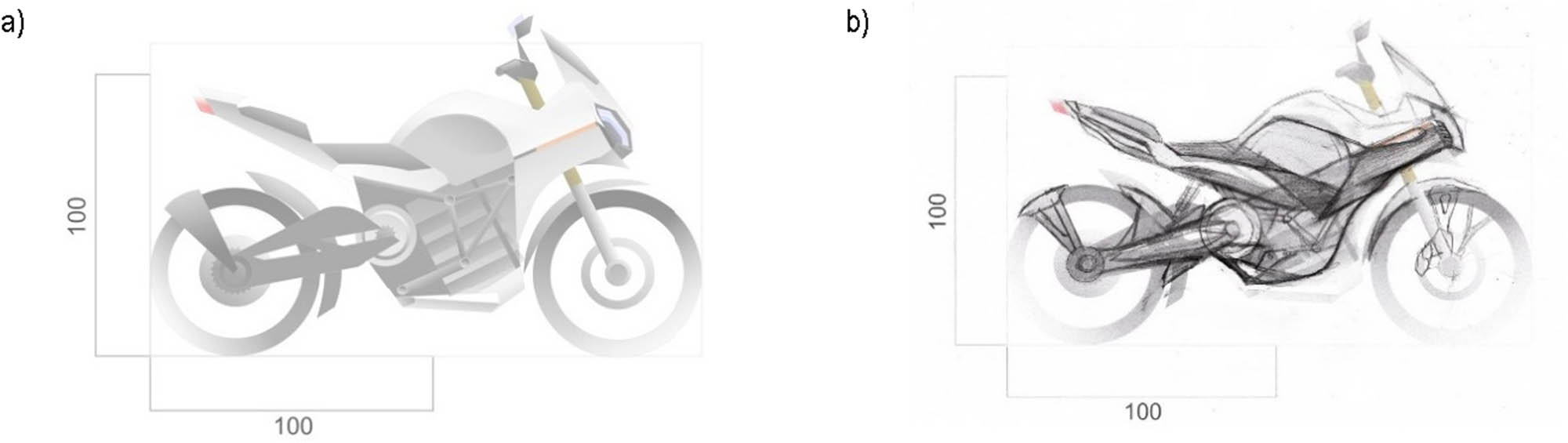
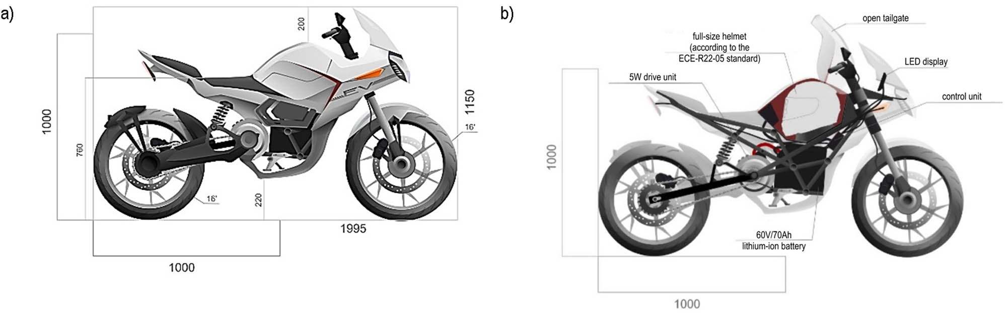
The vehicle length was assumed to be approximately 2,000 mm, the tank height measured from the ground was not exceeding 1,000 mm, and the seat height measured from the ground was less than 800 mm. The outer surface is supposed to be smooth, covered with glossy or matte varnish (Figures 4–6).
(a) Graphic design base and (b) electric motorcycle – freehand sketch of the motorcycle frame.
(a) Electric motorcycle – I variant sketch and (b) electric motorcycle – design sketch of variant I.

Electric motorcycle – sketch of variant II.
Defining the form of the most important components of the motorcycle in the next step, it was decided that the wheels would be made of a light shoulder construction, with a diameter of 16 in, and the width of the wheels would be in the range of 80–110 mm. The whole will be complemented by dark colors, slightly shiny or matte surface. The rims will be made of aluminum alloy. The bodywork, which is the appearance of a motorcycle, will be based on the scheme of the vehicle’s skull connected to the headlight. The bodywork forms an envelope around the steering wheel. Sharp geometry on the body side line is used, as well as a uniform color across the entire surface and minor color accents. The surface of the car body will be smooth, matte, or glossy, covered with varnish. The construction material of the car body can be fiberglass or properly selected plastic. The load-bearing element of the vehicle, the frame, is to be made of steel or aluminum pipes, which will reduce the weight of the vehicle. Among other elements that determine the appearance of the designed industrial form, one cannot fail to mention the seat, which should be made of leather or synthetic fabric material in dark gray. Another element is LED lighting and a color LED display located in a plastic structure (Figures 4–6).
Designing in accordance with the principles of universal design, it was assumed that an important element in the project is the renewability and low cost of production of structural elements. Therefore, it was envisaged that aluminum and magnesium alloy AlMg3Mn - 5454-H111, characterized by corrosion resistance and increased strength, would be used for the wheel rims of the designed motorcycle. The vehicle frame, which is the subject of further consideration, will be made of the AlZnMg - 7050-T7351 alloy, characterized by a high yield strength (435 MPa), in order to reduce the weight in relation to the initially planned steel pipes. The project will also use the S235JR structural steel alloy, which was selected as the material for the protective shell of the battery and as the material for the elements of the motorcycle suspension structure.
Based on the information provided above, a preliminary graphic design of the designed industrial form was developed (Figure 4a), which was verified in order to determine the shape of the frame (Figure 4b).
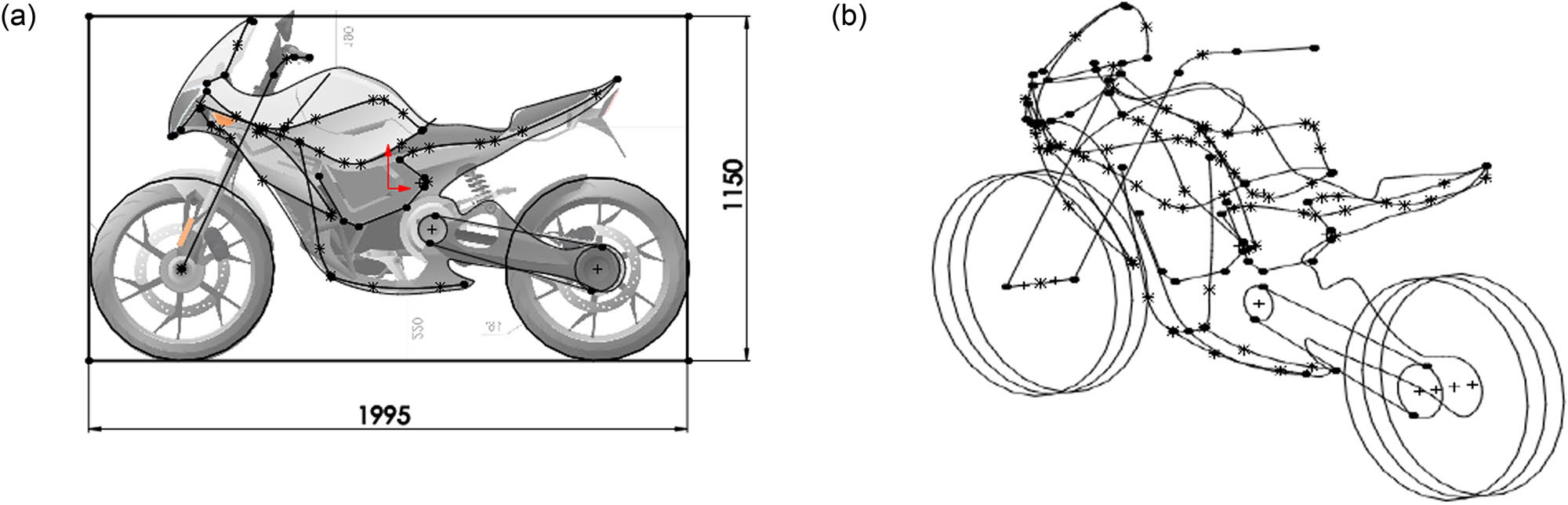
On the basis of the graphic design base and the designated lines in the freehand sketch, vector graphics were created showing the initial concept of the industrial design on a scale of 1:10 (Figure 5a). In the next step, an exemplary vehicle structure was drawn in order to better illustrate the arrangement of individual components (Figure 5b). Subsequently, changes were made to the design to achieve a smoother geometry, greater consistency of form, and an overall improvement in visual values (Figure 6).
The next stage of developing the industrial design was to create a virtual spatial model of the product. Making a spatial model is one of the most important elements of the design process, because it allows you to visualize the actual geometry of the pattern and analyze various parameters, such as dimensions, weight, area, strength, and others. The CAD software can be used for this purpose, or vector geometry programs can be used to obtain only geometry without the possibility of analysis. The following modeling process was based on the use of the SOLIDWORKS 2019 application [6], enabling a wide range of engineering activities – from graphic design to optimizing the structure using the FEM. In Section 3, the use of the FEM in industrial design will be discussed, e.g., in creating a spatial model of the vehicle frame structure, i.e., determining its geometry, checking technical parameters, and performing the FEM analysis [7], along with topographic optimization, in order to improve the strength of the support element that fastens the rear swingarm, while maintaining the relative weight of the element.
3 Designing and modeling the vehicle frame using FEM analysis
The chassis, i.e., in relation to two-wheeled vehicles more often used, the frame, is one of the most important structural elements of motorcycle construction. It is an element that connects all vehicle components, transfers the stresses resulting from the weight of the vehicle and users to the suspension elements. It is also responsible for the stiffness of the structure and its behavior under the influence of external forces. Frame parameters are often a determining factor in handling, driver and passenger positions, as well as the strength and overall behavior of a vehicle in the event of a collision.
It should be noted that in fact the process of constructing this element in each of the motorcycles takes months or even years, it also requires a specialized team of constructors, analyzing and testing the achieved results, and then changing the geometry, improving mechanical properties, and adjusting the cost and production method at the same time. It is also a process to be carried out simultaneously with the construction of other vehicle components, such as suspension, bodywork, etc. For the needs of the presented project, however, it is possible to outline the approximate shape of the structure and optimize the mass based on the assumptions made.
Some of the following assumptions were developed on the basis of the manual for the construction of motorcycle vehicles “Motorcycle Handling And Chassis Design” by Tony Foale, published in electronic form in 2002 [8].
3.1 CAD design of the frame and selected elements of the motorcycle structure
The first assumption is to match the frame structure to the shape and dimensions of the drive unit described above. Due to the nature of the work, the shape and overall dimensions of the subassembly, as well as its position in the mold, were assumed. For this purpose, in the SOLIDWORKS application [6], using the 3D Sketch tool, the general lines of the vehicle were drawn, which will serve as the basis for the construction (Figure 7).
(a) Spatial diagram of the vehicle in a flat projection and (b) spatial diagram of the vehicle in an axometric projection.
Then, a model of the drive unit was created and placed inside the body of the vehicle, adjusting the positions of individual components in the shell (Figure 8).

(a) Position of the drive unit inside the vehicle in plan views and (b) drive unit components: two batteries (1), motor (2), controller (3), radiator (4), and a shell covering the entire subassembly (5), made of 2 mm thick S235JR steel sheet.
In Figure 9, red areas mark the connection surfaces of the assembly with the vehicle frame. These are holes for M15 and M8 screw connections. Based on the shape of the frame, the position of the additional M15 connection is determined, connecting the side surface of the shell with the frame. The engine will be connected directly to the frame, using bolts, also connecting it to the shell (Figure 9).

Drive unit in axometric projection with connection surfaces for connecting to the vehicle frame (marked by red).
The task of the frame is to hold the subassembly, which is also a structural part, transmitting stresses. The load should not generate stresses in the frame exceeding the value determined on the basis of the safety factor. The mass of the assembly was estimated by estimating the masses of individual elements.
In the case of batteries, the energy to weight ratio for lithium-ion batteries is approximately 100–250 Wh/kg [9]. For simplicity, the value is averaged to 175 Wh/kg. Assuming that the battery is to have a capacity of 4 kWh, we can use the following simple equation to determine the mass:
where m battery is the weight of the battery used in the motorcycle.
The resulting mass of 23 kg was raised to 25 kg, assuming cell connections, transformer, and other components. The density of lithium-ion batteries is approximately ∼2,000 kg/m3 [10]. Using this fact, the volume of the battery solid was calculated, amounting to about 1.15 × 107 mm3, and a similar volume value was used in the construction of the battery model.
In the case of the engine, a mass of 12 kg was assumed after analyzing available commercial solutions. The same was done for the controller, assuming a mass of 2.5 kg, consisting of cables and other components. The mass of the cooler after the analysis of commercial solutions is 8 kg, which consists of the mass of pipes and coolant. For the shell, using S235JR material for the component, a weight of 4.92 kg was achieved. The final value was assumed as 5.5 kg, including fixings and other structural elements. This resulted from the shell design process and the estimation made in the SOLIDWORKS 2019 application [6]. The shell model is shown in Figure 10.

Model of the shell next to the drive system of the designed motorcycle.
Summing up the abovementioned values, it can be written that the final mass of the component is:
Multiplied by the gravitational constant of approximately g = 9.81 N/kg, the weight of the component is
From the above calculations, it follows that the load Q = 520 N, with vectors attached to the surfaces of the connection between the frame and the battery, should generate stresses lower than the yield strength of the material, divided by the adopted safety factor. It should also be noted that due to the above simplifications and assumptions, the actual force may slightly differ from the given value.
After determining the mass of the system, it is necessary to determine the weight of the users: the driver and the passenger. Assuming the total mass of passengers to be 200 kg, including additional loads such as clothes or hand luggage, the force directed along the vertical axis of the system is
In practice, this means that a static load of Q = 2,000 N fixed on the seat surface (Figure 11) should not generate stresses exceeding the permissible stresses.

The force of gravity of passengers on a spatial diagram.
In the next step, the angle of inclination of the front fork was determined. Determining the angle of inclination of the front fork will allow you to specify the position of the bearings that fix the handlebars to the vehicle frame (Figure 12). The angle between the normal to the contact surface of the wheel with the ground and the axis parallel to the axis of the fork is called the angle of attack. It is one of the variables responsible for the value of the distance referred to as the “mechanical trail,” affecting the geometry of the vehicle. The “mechanical trail” is designed to allow greater control of the motorcycle, it also affects the behavior of the vehicle when turning the steering wheel or tilting. This value also affects the behavior when braking with the front brake and the gyroscopic effect produced by the wheels, which in turn allows the vehicle to stay vertical [8] (Figure 12).
![Figure 12
Geometry of the angle of attack of the front fork (own study based on [8]).](/document/doi/10.1515/eng-2022-0569/asset/graphic/j_eng-2022-0569_fig_012.jpg)
Geometry of the angle of attack of the front fork (own study based on [8]).
Most motorcycles produced on the market have an angle of inclination with values in the range of 23°–30°, of which 27° is considered the “magic value” [8] (Figure 13). Based on this knowledge and due to the generally assumed dimensions of the vehicle, the above angle was selected for the construction of the designed motorcycle (Figure 13). Then, changes were made to the scheme and the mounting surface of the bearings was determined.

The angle of inclination and the mounting surface of the steering wheel bearings.
The rear suspension includes a fork or forks, shock absorbers, chains and various types of fastening, and stress transfer structures. There are many types of rear suspension, differing in the number of shock absorbers, wishbones, their position, shape, and mechanically interacting elements.
In the project discussed in this work, a construction based on a combination of one shock absorber and a two-arm fork made of aluminum alloy was used. A chain drive was also used. The frame structure needs to be reinforced in the area where the rear fork and shock absorber are mounted, due to the relationship between the forces acting on the wheel and the shock absorber.
This dependence applies to the forces during the “folding” of the suspension: the wheel moving along the vertical axis transfers the force to the shock absorber, as the difference between the distance covered by the wheel and the distance covered by the shock absorber attachment point increases, the force acting on this point increases. This increase is the square of the ratio of roads covered [8] (Figure 14). The load on the wheel (F) is half the load on the spring (2F), but the vertical movement on the wheel (A) will be twice that of the spring (B). In simple terms, this means that the smaller the stroke of the shock absorber compared to the stroke of the rear wheel, the greater the forces acting on it, which means an increase in the stress on the shock absorber attached to the frame. Therefore, this area of the structure must be reinforced.
![Figure 14
Typical 2:1 leverage system (own study based on [8]).](/document/doi/10.1515/eng-2022-0569/asset/graphic/j_eng-2022-0569_fig_014.jpg)
Typical 2:1 leverage system (own study based on [8]).
Bearing this dependence in mind, the mounting positions of the shock absorber and the rear fork were determined in the spatial scheme so as to obtain the most favorable arrangement of elements in terms of weight and strength (Figure 15).

Flat diagram of the shock absorber position.
Based on the above sketch, the component mounting surfaces were created as part of the frame geometry guidelines.
As the last assumption, the type of frame structure was defined. The simplest division of the types of construction of motorcycle frames in terms of production is the division into frames: welded from semi-finished products, welded from elements after plastic processing and from cast elements. For the designed vehicle, a tubular and skeletal structure was assumed, made of welded aluminum pipes made of AlZnMg - 7050-T735 material. It should be noted that at the same time it will also be a structure in which the drive unit designed above will be a structural part, partially responsible for the rigidity of the structure. In the area of engine mounting, a semi-finished product made using additive manufacturing technologies will be attached to the structure.
After determining all the assumptions for the frame construction, a spatial diagram of the structure was obtained, imposing some dimensions (Figures 16 and 17). On its basis, the construction of the frame will be made.

Spatial diagram of rear suspension mounting.

Spatial diagram of the vehicle with spatial guidelines.
Once the part is ready, the modeling process can begin. It was started with the projection of the connection surfaces and the creation of appropriate solids on their basis (Figure 18).

Solids of the mounting frame of the vehicle subassembly.
On the basis of the obtained geometry, guiding curves were created in accordance with the generally accepted design assumptions. For this purpose, the axes of the resulting cylinders were created and, using the 3D Sketch tool in the SOLIDWORKS 2019 application [6], lines and curves corresponding to the axes of aluminum tubes were determined. The dimensions of the created solids were also adjusted (Figure 19).

The 3D sketch of the frame structure.
Then, surfaces normal to the axis were created and sketches were drawn in them, reflecting the cross-section of the pipe. During the design work, defined global variables were used to determine pipe diameters and their thickness. Global variables for the designed frame were determined based on tables of normal dimensions and catalogs of standardized semi-finished products. In the next step, using the sweep operation, the body of the wrought pipe, which is part of the structure, was created (Figure 20).

Sweeping a structure element in SolidWorks application.
The operation was repeated for all the curves on one side, and then the mirror operation was used, achieving the initial geometry of the frame. The distances from the elements of the scheme were checked and the dimensions of the openings were refined. Due to the formation of undesirable geometry inside the holes and pipes, it was removed using the extruded cut and extruded cut along the path (Figure 21).

(a) Frame model after initial operations and (b) model of the frame after the initial operations inside the diagram, along with the indicated position of the drive system.
After checking the correctness of the geometry, changes were made to the structure, shock absorber mountings and angles stiffening the structure were added, and several structural changes were made (Figure 22). After these operations, the model was divided into three parts: the main part of the frame and two rear suspension arm mounts, in order to perform a topology analysis of these elements. The resulting models were connected by bonds (Figure 22). The prepared model was then simulated using the FEM.

(a) Modified frame model and (b) frame model after initial modifications inside the diagram.
As shown in Figure 22, the entire motorcycle frame consists of a welded structure of aluminum tubes marked as (1) and an additional element marked as (2). Element (2) connects the proper part of the frame, supports the engine and is the place where the rear swingarm is attached. Due to the rather complex shape, in the discussed project it was decided to make this element using additive manufacturing techniques, through 3D printing from metal powders. This will allow us to obtain a shape unattainable by other production methods
3.2 Simulation tests of the frame support element – an element produced by incremental methods
The strength of the frame connectors can be assessed in several ways. The first one is standard analytical calculations, based on commonly known formulas, tables, and strength graphs [11,12,13]. The second option is to make a prototype and subject it to strength tests. The third possibility is comprehensive simulation research, conducted on virtual models, using CAE tools. Among the simulation studies, the FEM [7], widely used in engineering, should be mentioned, which is often extended by topology research, referred to in many sources as topological optimization. Topological optimization is also very often used in the process of designing structural elements produced by incremental methods, e.g., during the metal powder printing process. This production process makes it possible to obtain shapes that are difficult to achieve by conventional manufacturing methods. Based on the results of the simulation study, which is topological optimization, a geometry with better mechanical properties is generally created.
Topological optimization [6] consists in finding a geometry that meets specific and well-defined strength requirements, based on the original shape of the element. It is generally used to reduce weight, determine the best stiffness-to-weight ratio, or minimize displacements of a structure subjected to loads. During the design process, based on topological optimization, on the basis of the solid obtained from the simulation test, the tested element is adapted to its results, working out a compromise between technological possibilities and optimal geometry [6]. Among the many publications in which attention is paid to the issues of topological optimization, one can refer to [14,15,16,17,18,20].
In the design of the described motorcycle, it was assumed that one of the parts of the frame, fixing the engine, would be manufactured using unconventional production methods – additive methods, allowing the creation of complex geometry in all axes of the coordinate system. Therefore, the only geometric assumptions during the FEM simulation study and topological optimization will be the behavior of the solids surrounding the areas of contact with other elements and the minimum thickness of the geometry.
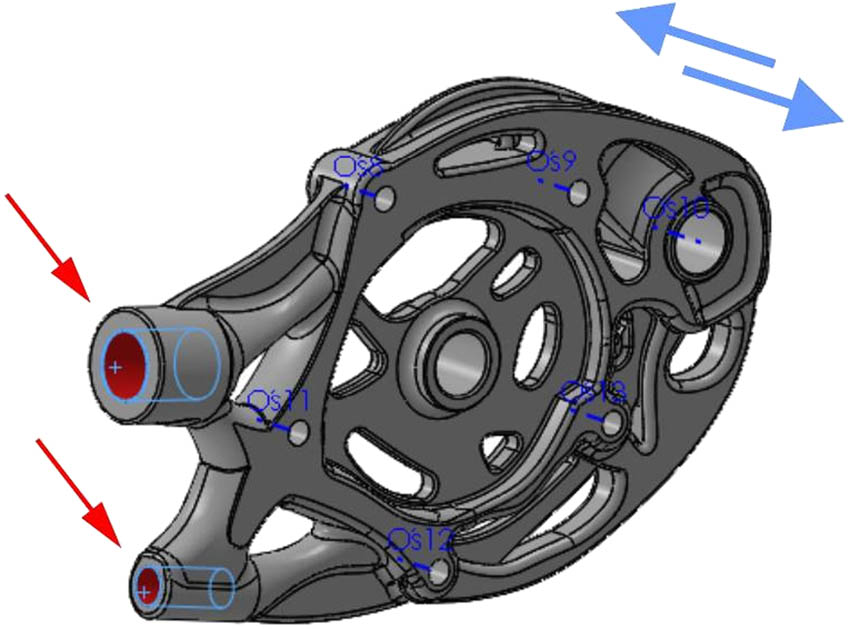
The tested element – presented in Figure 23, is a structural part of the vehicle frame, it fastens the frame skeleton to the drive unit, while being the point of attachment of the rear swingarm. The block has holes for M8 screw connections with the assembly and the motor. The part also connects two pipes that are part of the skeleton. The applied connection fixes the ends of the pipes inside the openings, enabling bolt or weld connection. In Figure 23, the connection surfaces are marked in red.

Connection surfaces of the tested element.
The initial mass of the element, estimated using the CAD module of the SOLIDWORKS 2019 application [6], is approximately 1,110 g, using the material of the 7050-T7351 aluminum alloy for the model. The 7,000 series aluminum alloy is an elastic-plastic material, one of the materials used in additive manufacturing. It should be emphasized that the purpose of the study is mainly to increase strength, taking into account the low mass of the original element.
Conducting simulation tests requires proper definition of the forces acting on the frame and its components. The forces acting on the elements will be distributed evenly on both fasteners. The distribution of static forces acting on the elements was assumed as 50% of the weight of the drive unit (denoted as m drive_unit), 60% of the weight of the frame skeleton (denoted as m skeleton_frame), and 100% of the weight of the mass associated with the users (denoted as m users), and 50% of the assumed weight of the remaining vehicle elements, amounting to about 40 kg, was added to these values (denoted as m other_items). The obtained value was divided by two in order to obtain the force acting on a single element – there are two symmetrically located tested elements in the frame. It should be noted that dynamic forces related to the movement of the vehicle or the operation of the rear suspension of the vehicle were not assumed. Therefore, the geometry adjustment process will assume a thicker solid on the axes between fixtures. The mounting surface of the swingarm was assumed to be stationary. The distribution of forces was assumed to be 90% of the value for the mounting elements with the frame and 10% of the value for the holes for screw connections.
Using the SOLIDWORKS 2019 application [6], the weight of the frame skeleton was estimated at 2.02 kg (Figure 24).

Skeletal shape of the frame, without rear swingarm mounts.
Then, the mass of the system acting on both connectors was calculated in accordance with the previous paragraph. The calculations were carried out assuming the acceleration due to gravity, g = 9.81 N/kg, and the obtained value was divided by two.
As can be seen, the load on the motor mount is equal to 1,215 N.
Simulation studies began with the analysis of the original geometry with assumed loads. In order for mass to be removed from an element, it must initially meet the strength requirements. A safety factor of k = 3 was assumed for the structure, which for the material used means reference stresses of σ ref = 145 MPa [12,13].
In the next step, a static analysis was performed in the SOLIDWORKS 2019 application [6], using the SIMULATIONS add-in. On the developed model of the element, the assumed loads were imposed, the surface of the rocker arm mounting hole was immobilized and a finite element mesh was created. To fill the mesh, tetrahedral solid elements of the SOLID type, of high quality, were adopted. This means that it is a second-degree element [6], with ten nodes – four at the vertices (corners) and six at the midpoints of the edges. The selection of the second-degree element, not the first one, which is an element of draft quality (a tetrahedron with four nodes in the corners), allows for a better representation of the curvature before and after deformation as a result of acting external loads. The high-quality finite elements with ten nodes assumed in the model represent the displacement field in the form of a parabolic function. As a consequence, the stress and strain fields are approximated in a linear way. In order to obtain reliable results, in the model under consideration, according to the suggestions of the authors of the SOLIDWORKS 2019 application [6], at least two elements were used in the thickness of the model. The finite elements adopted for filling in the model had four Gaussian points each, which means four points of numerical integration in the element. The numerical model of the considered element consisted of 11,169 finite elements (the total number of nodes was 18,031), with an average element size of 8.6 mm. Figure 25 shows the model of the tested element with applied forces (purple arrows) and fastening as stationary geometry (green arrows). Figure 26, on the other hand, shows the discretized model of the tested element, including the mounting and the applied load.

Static forces acting on the tested element.

Grid of the static analysis of the tested element.
Figure 27 presents the distribution of effective stresses calculated according to the Huber-Mises-Hencky (HMH) hypothesis [11,12,13] for the considered element. The maximum effective stresses in the block are approximately 94 MPa, which means that the element does not deform plastically. This value is about 22% of the yield point σ 0 and 65% of the reference stresses, determined from the formula (9). Then, the calculations were repeated for the model with 16 Jacobian points, which did not affect the obtained results. It should be noted that the Jacobian points are points used to check the Jacobian ratio which is a measure of mesh quality. Change from 4 to 16 points does not affect the results in terms of stress, but differently highlights the mesh quality. As can be seen, the greatest stresses radiate from the surface of the rear control arm mounting hole, which requires adjusting the tested element in order to strengthen it. The remaining area of the geometry is generally characterized by relatively low values of effective stresses (Figure 27).

The HMH stress diagram of the static analysis of the tested element.
When analyzing the obtained effective stress distributions, the reader may notice that the SOLIDWORKS application [6] displays most of the simulation results using the deformation scale [6]. The deformation scale refers to the scale factor that the program uses to scale the deformed shape of the model. The value of the scale factor depends on the largest dimension of the model and the calculated deformations. For example, a scale factor of 50 means that the largest deformation calculated in the simulation add-in of SOLIDWORKS application [6] is 50% greater than the largest dimension of the smallest bounding box surrounding the model. A larger deformation scale factor improves the visualization of deviations that are much smaller compared to the original dimensions of the model. In the distribution of effective stresses presented in Figure 27, the automatic deformation scale was 69.2843. This means that the actual displacement has been magnified that many times. This procedure is used in order to better present the way the model works [6].
After confirming the strength of the structure, the topology study was started [14,15,16,17,18]. Due to the characteristics of the process performed by the program, the geometry of the element was slightly simplified, the model was made thicker, and reinforcement was introduced by adding material in the place where the rear swingarm is attached. At this stage of the design, it turned out that the weight of the element increased significantly to 1.9731 kg (Figure 28).

New form of the tested element. Loads (purple arrows) and fastenings (green arrows) in the topology study.
In the improved fastening model, similar to the previous study, during topological optimization (which other researchers used in their works [14,15,16,17,18]), forces were fixed and the model was immobilized (Figure 28). The test objective was defined as “The best stiffness to mass ratio,” and then the mass linkage goals were selected as reducing it to 50% of the original mass and linking the maximum stresses with the previously defined value of allowable stresses (assuming that the yield strength of the material is σ 0 = 435 MPa, and allowable stresses σ ref = 143.5 MPa – i.e., 33% of the yield strength – this means that the calculations were carried out with the assumption of the safety factor x = 3 [13]).
Before the analysis, it was indicated that the minimum thickness of the member should be 6 mm in each axis. All contact surfaces are marked as areas to keep and are 4 mm thicker. The plane of symmetry and the direction of molding the solid were not defined due to the assumed production method. After defining all assumptions of the analysis, a finite element mesh was created with four Gaussian points in a high-quality finite element (tetrahedron with ten nodes, as in the study described above), total number of nodes –115,996, total number of finite elements – 78,460, and an average element size of 4.65 mm. Figure 29 shows the FEM model used in the topological optimization simulation.

Solid mesh in a topology study.
The study of topological optimization required the application processor to run 36 iterations of the solid geometry. The result of the optimization is shown in Figure 30, which shows the graph of the mass distribution that can be removed. For further analysis, a variant with an element mass of 1.0242 kg was adopted, which means a reduction of almost half the value before the test, similar to the original model, whose mass was 1.9731 kg.

Results of element topology simulation.
Figure 31a shows the tested element smoothed after the topology test, on the basis of which a new variant of the structure element was developed. Therefore, the obtained geometry (in the form of a points cloud) was exported to a file with the *.stl extension, and then, when modeling a new part, the obtained geometry was imported to it, and then its transparency was changed. Individual elements of the original part were also projected using the 3D Sketch tool in SOLIDWORKS application [6]. Based on this data, a new part was constructed as shown in Figure 31a.

(a) Smoothed element mesh and (b) the process of modeling a new solid of the tested element.
The next step was to create a new part and import the resulting geometry into it, then change its transparency. Individual elements of the original part were also uploaded in the form of 3D sketches. Based on this data, a new part was created, constructed as shown in Figure 31b.
After the initial model creation, as well as the process of gradual improvement of the geometry in terms of strength, a solid with a mass of 1 kg was obtained, as shown in Figure 32, which was subjected to another FEM simulation, carrying out a static analysis study, based on restraints and common loads with the study of the initial geometry, only changes were made to force distribution of 121.5 N, adding two additional surfaces of its impact, which are the bearings of the motor shaft. In the model, a mesh of tetrahedral ten nodal finite elements with four Gaussian points in the element – solid elements of high quality – was created. The generated mesh consisted of 38,914 finite elements (i.e., 66,109 nodes) with an average element size of 4.95 mm.

Additional load mounting surfaces.
The results of the simulation are shown in Figure 33. In the tested element, the estimated maximum effective stresses calculated according to the HMH hypothesis [11,12,13], with the assumed loads and fastenings, are approximately 32 MPa, which means a value nearly three times lower compared to the model test (i.e., 94 MPa), and at the same time more than four times lower than the accepted allowable stress (i.e., 143 MPa). As can be seen, the effective stresses are more evenly distributed in the solid, which results in a prolonged process of material degradation. It should be noted that the production method used (incremental method – 3D printing from metal powders) may reduce the mechanical properties of the material, but due to the achievement of stresses more than ten times lower than the yield strength of the selected material (435 MPa), this issue can be omitted. The numerically estimated displacements in the solid reach a maximum value of 0.15 mm (Figure 34).

The distribution of the HMH effective stress in the modified solid.

The distribution of the displacement in the modified solid.
The weight of the modified component is 1.001 kg, which means a decrease in weight of 109 g compared to the initial value (1.110 kg). The resulting mass of the element can also be reduced by using an appropriate structure instead of full filling inside the geometry, which may be the subject of other considerations or a research project in the future. Comparing the original element and the element obtained on the basis of topological optimization (Figure 35), it can be seen that the general profile of the element has been preserved, changing only its width in the places where the bolts and the rear wishbone are attached. A hoop supporting the motor shaft has also been added (Figure 35). Figure 36 shows the entire vehicle frame, including the element obtained as a result of topological optimization.

Visual comparison of the mounting bodies.

The vehicle frame after the use of modified solids.
3.3 Simulation tests of the frame support element – an element manufactured by an alternative method
On the basis of the geometry developed in the topological optimization, an alternative version of the element connecting the main frame and the rear swingarm was developed, which can be produced in the casting process (Figure 37). The demolding direction parallel to the axis of the M8 holes was determined (blue arrows in Figure 37), and then the geometry was created in accordance with the technological possibilities. The element was adapted to create a casting mold, and then to make holes impossible to be included in the form by drilling – red arrows in Figure 37. The weight of the estimated solid is about 1 kg.
Alternative solid with marked drilling surfaces and demolding direction.
The obtained geometry was subjected to static analysis, assuming loads and restraints in accordance with the previous test. A mesh of ten nodal tetrahedral finite elements was created with four Gaussian points in an element, total number of nodes of 76,406, total number of elements of 37,823, and an average element size of 6.27 mm. The numerically determined effective stresses, calculated according to the HMH hypothesis, do not exceed the value of 25 MPa, which is a value 7 MPa lower than in the study of the solid intended for production by incremental techniques (Figure 38). The estimated stress distribution is characterized by less dispersion compared to the previous variation. Displacements also slightly decreased (Figure 39). The obtained results allow to conclude that the structure meets the requirements set out at the beginning. It should be noted, however, that despite the better mechanical properties of the alternative element (manufactured by casting), it may turn out to be problematic in the technological process and may be characterized by lower stiffness under the influence of torsional forces.

The distribution of the HMH effective stresses in an alternative solid.

Distribution of the calculated displacements in an alternative solid.
3.4 Analysis of the structure of the proper frame using the FEM
The next step in the frame design process is to check its stiffness and eliminate areas of high stress by analyzing the geometry using the FEM. For this purpose, two simulation tests were carried out: a static simulation of the frame under full load and a frame test under the force acting on the frame in the process of rapid braking.
3.4.1 Full load frame test – FEM analysis
Simulation studies, as before, were performed using the SIMULATIONS add-in in the SOLIDWORKS 2019 application [6]. The imported frame had to be properly fixed and loaded. The boundary condition of the fixed geometry was assumed as the front fork and rear swingarm mounts (Figure 40). In the next steps, the structure had to be properly loaded, taking into account all components derived from the weight of the drive unit, the weight of the driver and passenger, the weight of the bodywork and other components of the motorcycle structure, and the reaction force of the suspension acting on the shock absorber mounting (Figures 41–43).

Fixed geometry in a static load study (boundary conditions are marked using green arrows).

(a) Load Q 1 in a static load test and (b) load Q 2 in a static load test.

(a) Load Q 3 in the static load test and (b) load Q 4 in the static load test.

Force F 1 in a static load test.
The load from the drive unit was divided into two different parts. It was assumed that the frame elements are affected by 75% of the weight of the drive unit on the M15 screw holes (Figure 41a) and 25% of the weight of the drive unit on the holes of the M8 screw connections inside the connector bodies (Figure 41b). The applied forces have been rounded to units.
The load of the driver and passenger with the value Q 3 = 2,000 N was imposed on the frame in the designated area of the seat attachment (Figure 42a). The load on the car body and other elements was assumed as Q 4 = 300 N. The model was divided and the force was fixed on an exemplary surface transferring the load (Figure 42b). The suspension reaction force acting on the shock absorber mounting was assumed as F 1 = 500 N. The force vector was drawn along the assumed shock absorber axis (Figure 43).
After mounting the entire frame and imposing forces on the system, the model was discretized. A mesh of tetrahedral ten nodal finite elements with four Gaussian points in the element was created. The total number of elements in the model was 101,840, and the number of nodes was 198,953. The model used grid control for selected areas, changing the size of the finite element in the range of 6.21–30.61 mm. The material of the elements has not been changed. Figure 44 shows the discretized model of the frame with the rocker arm connector intended for production by 3D printing, along with the assumed boundary conditions – fixed mounting (green arrows) and applied load (purple arrows).

Mesh of the whole frame of the electric motorcycle, used in a static load test.
The performed simulation shows that for the given boundary conditions and load, the effective stresses calculated according to the HMH hypothesis are lower than the assumed yield point, but relatively high – in some places they exceed 350 MPa – so they are more than 2.5 times higher than the allowable stresses determined by the formula (9) – σ ref = 143 MPa. Figure 45 shows the places where the stresses are greatest. Estimated results indicate the need to strengthen the structure. The occurrence of maximum effective stresses in the shown place results from the fact that the structure does not contain pillars supporting the frame in the resting place of the driver and passenger, which results from the adopted style of the vehicle body to make it visually attractive, in accordance with the design principles.

The distribution of the HMH effective stress, calculated in a static load test.
In order to eliminate the value of effective stresses in the frame structure, it was strengthened by using additional elements produced by plastic working methods and by casting. Angles under the seat were abandoned and angles were added in areas of high stress, and the pipes connecting the seat were thickened. A comparison of both frame models is shown in Figure 46. Changes introduced to the frame structure are marked in red in Figure 46b.

Structure – full frame of electric motorcycle before (a) and after (b) modifications in the static load test.
In the corrected version of the frame, fixed attachments were added as before and the abovementioned loads were applied (Figure 47). The virtual model was discretized by filling up to tetrahedral SOLID finite elements with ten nodes and four points of numerical integration. As before, in selected areas of the structure, mesh control was applied by changing the size of the finite element, in the range of 6.5–30.06 mm. The entire frame model was filled with 112,362 finite elements. The total number of nodes in the model was 207,211. The estimated effective stress in the entire model turned out to be lower than the value of allowable stress determined by the formula (9) (σ ref = 143 MPa). The maximum value of effective stresses is 76% of allowable stresses. The simulation carried out indicates an even distribution of stress in the considered structure, in relation to the applied boundary conditions and load (Figure 47).

The distribution of the HMH effective stress, estimated in the static load test after modifications.
As shown in Figure 48, the frame moves – flexes up to 6 mm. This deflection was recorded at the end of the seat mounting bracket. It may seem that this is a significant value, but it does not threaten the structure. The estimated amount of deflection is due to the large moment generated by the mass of the passenger. Taking into account the frequency of such a situation, driving with a passenger, which can happen quite rarely, the estimated result can be considered acceptable (Figure 48).

The Displacements distribution, calculated in the static load test after modifications of the frame.
Figure 49 shows the numerically estimated deformations (strains) in the frame structure. As can be seen, their highest value appears in places where the effective stresses were the highest, which is a completely natural and unquestionably acceptable phenomenon. It is worth noting that the maximum deformation value does not exceed 0.13%, which is an acceptable result.

Distribution of the deformations (strains) in the static load test after modifications of the frame.
3.4.2 Testing the frame under the braking force of the system
An important element when riding a motorcycle is the braking situation – the situation of a sudden slowdown of the vehicle. To determine the level of deformation and stress in the frame in such a situation, it was decided to run a simulation when the driver uses only the front brake. In order to carry out the numerical estimation, the initial velocity of the vehicle was assumed, v 0 = 50 km/h = 14.(8) m/s ≈ 15 m/s, final velocity of the vehicle v 1 = 0 km/h = 0 m/s, braking time t = 4 s, mass of the system (motorcycle and rider): m = 230 kg. To calculate the force F, the following work formula W [19] is transformed:
where W is the work, F is the force, and s is the distance.
The energy of the system can be determined from the kinetic energy formula [19] as follows:
Then, the required delay is evaluated by
Using the formula for the distance in uniform decelerated motion, the braking distance of the system can be calculated [19] as follows:
Therefore, the forces acting on the system during braking are
It should be noted that the calculations omitted the friction force, air resistance, spring action of the front suspension, reducing the force acting on the frame, assuming the ideal stiffness of the component. For this reason, it was assumed that the value of 143 MPa could be exceeded by 10%, which means the maximum allowable stress is 157.3 MPa. As a result of elementary calculations, a static force of F = 1987.5 N was obtained, acting on the front fork mounting in the opposite direction to the velocity vector. In order to simulate the behavior of the frame in the described situation, a designated force was applied to the mounting surface of the steering wheel bearings and the load resulting from the mass of the driver and passenger was reduced to Q 5 = 1,000 N. The force area was also reduced, assuming only the mass of the driver. The reaction force of the suspension was also reduced to 250 N. The remaining loads were left. The immobilization of the front fork mount has been removed. The frame model with applied boundary conditions (green arrows) and with applied load (purple arrows) is shown in Figure 50.

Braking force in a static braking test.
The virtual model was discretized by filling up to tetrahedral SOLID finite elements with ten nodes and four points of numerical integration. As before, in selected areas of the structure, mesh control was applied by changing the size of the finite element, in the range of 6.5–30.06 mm. The entire frame model was filled with 112,362 finite elements. The total number of nodes in the model was 207,211. As a result of the numerical calculations (Figure 51), the maximum effective stresses calculated according to the HMH hypothesis in the frame structure slightly exceed the value of 177 MPa. This is an excess of the allowable stresses determined by formula (9). In this regard, it is necessary to strengthen the structure.

The HMH effective stress distribution, calculated in a static braking test for frame of the electric motorcycle.
Due to the fact that the effective stresses were exceeded by almost 25% of the reference stresses, areas characterized by high stresses in the previous simulation were added by adding pipes supporting the seat support and the adjacent angle bars were thickened. Figure 52 shows the reinforced frame.

Areas of modification in the static braking test for frame of electric motorcycle.
The reinforced model of the frame was divided into tetrahedral ten-node finite elements with four Gaussian points in the element. As in the case of previous simulations, the control of the size of elements in the range of 6.05–30.29 mm was used. The total number of nodes that make up the model is 208,292, i.e., 113,153 SOLID finite elements. The fixation and loading of the frame were adopted from the previous simulation. Estimated effective stresses (Figure 53) at two points do not exceed 150 MPa. This value is 7 MPa higher than the permissible stresses determined by formula (9), i.e., 143 MPa; however, at the beginning of the analysis, it was indicated that the calculations omitted the friction force, air resistance, and elastic action of the front suspension, reducing the force acting on the frame, assuming an ideal component stiffness. For this reason, it was assumed that the value of 143 MPa could be exceeded by 10%, which means the maximum allowable stress is 157.3 MPa. Therefore, due to the assumed deviation of the allowable stresses, it allows the initial acceptance of the structure. The maximum displacement in the structure is slightly more than 4 mm (Figure 54). A significant part of the displacements is in the range from 0.5 to 2 mm, which is an acceptable result. Maximum deformations in the frame structure do not exceed 0.16%, which is also an expected result (Figure 55).

The HMH effective stress distribution estimated in the static braking test after modifications of the frame of the electric motorcycle.

The distribution of the displacements in the static braking test after modifications of the frame of the electric motorcycle.

Distribution of the deformations (strains) in the static braking test after modifications of the frame of the electric motorcycle (the final form of the frame adopted in the design project).
4 Summary, final conclusion, and presentation of a new industrial form
This study presents the use of the FEM in solving real engineering problems, using the example of an electric motorcycle design project. A simplified scheme of industrial design was presented, followed by an indication of how to use the capabilities of the selected CAD/CAM/CAE software in industrial design. Using concurrent design based on the CAD system with the simultaneous use of CAE modules, the interdisciplinary of industrial design engineering was shown, which cannot exist without access to numerical methods.
Summing up the results presented in the study, they may be characterized by a significant discrepancy with the actual values in favor of the structure, due to the study of the model not connected to any other elements of the vehicle. On the basis of the results, it is possible to assume the acceptable strength of the structure, which means that the structural assumptions are met. The value of the weight of the frame after modifications is 5.54711 kg. Taking into account for minimum weight of welds and the use of additional reinforcing elements, the final mass was assumed as 6 kg. When evaluating the presented estimates, a number of assumed simplifications should be taken into account. In the simulations, the effect of welds was omitted, a homogeneous isotropic material was assumed. In some of the simulation tests, the friction force, air resistance, and elastic action of the front suspension, reducing the force acting on the frame, were omitted, assuming ideal component stiffness. As it is known, during numerical calculations, sometimes a small change in boundary conditions and load can lead to rapid changes in the obtained results. In the developed model of the frame, efforts were made to reflect all possible actual frame attachment and its load.
When conducting a series of numerical calculations using the SOLIDWORKS 2019 application [6], in each of the considered cases, higher-order SOLID finite elements with ten nodes and four Gaussian points were used. The developed divisions for subsequent mesh elements, in which the size of the finite element was often controlled, guaranteed convergence with the mesh filled with higher-order finite elements with 16 points of numerical integration.
In the electric motorcycle project discussed in this article, the close relation between CAD and CAE modules was used, looking for the best solution in the construction of the motorcycle frame. By conducting a series of numerical simulations based on the FEM and topological optimization, the final shape of the frame and the rear control arm mounting was presented. The designed structure was optimized in terms of mass and effective stress distributions determined from the HMH hypothesis. The resulting frame model was adapted to the design project (Figure 56). The study indicates the need to use the FEM and CAD/CAM/CAE applications at almost every stage of engineering design.

(a) Visualization of the new form of the electric motorcycle in plane (a) and in an axometric (b) projections.
During the preparation of the presented project, and next article, the authors considered carrying out some analyzes in other computational packages using the FEM (e.g., ADINA, ABAQUS, ANSYS). In the end, they stayed with the SOLIDWORKS 2019 application [6], which offers both work with the CAD, CAM, and CAE modules. Conducting the numerical analyzes presented in the previous paragraphs, the finite element model was initially optimized by selecting for all simulations the filling of discrete models with spatial finite elements of the SOLID type of higher order, with ten nodes and four Gaussian points. Developed for subsequent mesh elements, in which the size of the finite element was often controlled, they guaranteed convergence with the mesh filled with higher-order finite elements with 16 points of numerical integration. The use of ten nodal spatial finite elements of the SOLID type with only four points of numerical integration is fully justified in the case of low-strength structures, in which the effective stresses do not exceed the yield point. The analyzes carried out showed that the designed structure meets the assumptions, and the maximum effective stresses are lower than the allowable stresses, determined as 1/3 of the yield strength of the material used to make the frame.
The model of engineering work presented in this study, industrial design, solving engineering problems, construction problems, strength problems indicates the need for interdisciplinary education of engineers and an interdisciplinary approach to the engineer’s work in solving various issues. An example of this can be the manuscripts [20,21,22,23,24], in which the authors, by publishing their results, indicate interdisciplinary preparation for the role of an engineer, scientist, or researcher. In the study by Graba and Grycz [20], the FEM and structure topology analysis were used to propose a new industrial form of a flying drone. In the study by Kostka et al. [21], the aim of the scientific contribution is to point out the possibility of applicability of cylindrical shells with a constant elliptical cross-sectional shape for stability loss analysis. The authors present both experimental and numerical research work. In the study by Assimi et al. [22], authors present a genetic programming approach for simultaneous optimization of sizing and topology of truss structures. It aims to find the optimal cross-sectional areas and connections of the joints to achieve minimum weight in the search space. Kopas et al. [23] presented the analysis of selected mechanical properties of weld joints of AlMgSi07.F25 aluminum alloy based on experimental and numerical analysis. Blatnický et al. [24] presented a partial solution to the conception of the design of a manipulator for handling goods in particular difficult and limited operation conditions. It is considered to transport materials between two destinations.
To sum up, a good engineer must be highly interdisciplinary educated and prepared for scientific and research work. This is why we have prepared this article, to show our preparation and expectations for twenty-first century engineers.
-
Conflict of interest: Authors state no conflict of interest.
-
Data availability statement: Data sharing is not applicable to this article as no datasets were generated or analysed during the current study.
References
[1] Electric motorcycles and scooters. Available online: https://tiny.pl/wnvb2 (accessed on 28 November 2020).Search in Google Scholar
[2] Zero Motorcycles. Available online: https://tiny.pl/wnvbb (accessed on 28 November 2020).Search in Google Scholar
[3] Zero S. Available online: https://tiny.pl/wnvb3 (accessed on 28 November 2020).Search in Google Scholar
[4] Grycz A. Preliminary design project for electric motorcycle. Engineering Thesis, Kielce University of Technology – Faculty of Mechatronics and Mechanical Engineering – Department of Metrology and Non-conventional Manufacturing Methods, Kielce, Poland, 17 February 2021. (Polish).Search in Google Scholar
[5] Tjalve E. Designing Industrial Forms. Arkady; Warsaw; 1985 (Polish).Search in Google Scholar
[6] Solid Works 2019 Documentation. Available online: https://tiny.pl/wnvzm, (accessed on 21 February 2023).Search in Google Scholar
[7] Zienkiewicz OC, Taylor RL, Zhu JZ. The Finite Element Method: Its Basis and Fundamentals. 6th edn., Oxford: Elsevier; 2005. https://tiny.pl/wnv3r (accessed on 22 February 2023).Search in Google Scholar
[8] Foale T. Motorcycle Handling And Chassis Design; Motochassis by Tony Foale. ISBN – 84-933286-3-4, Spain; 2002.Search in Google Scholar
[9] Lithium-ion battery. Available online: https://tiny.pl/wnbhp (accessed on 10 December 2020).Search in Google Scholar
[10] Analysis of Long-Range Interaction in Lithium-Ion Battery Electrodes. Available online https://tiny.pl/wnbh81 (accessed on 10 December 2020).Search in Google Scholar
[11] Kumar BR. Strength of materials. CRC Press. p. 300.Search in Google Scholar
[12] Bansal RK. A textbook of strength of materials: Mechanics of solids. New Delhi, India: Laxmi Publications; January 2012.Search in Google Scholar
[13] Niezgodziński ME, Niezgodziński T. Formulas, charts and strength tables. PWN Warsaw; 1977 (Polish).Search in Google Scholar
[14] Yoon GH. Topology optimization method with finite elements based on the k-ε turbulence model. Comput Methods Appl Mech Eng. 2020;361:112784. https://tiny.pl/wnbx2 (accessed on 22 February 2023).10.1016/j.cma.2019.112784Search in Google Scholar
[15] Ramesh S, Handal R, Jensen MJ, Rusovici R. Topology optimization and finite element analysis of a jet dragster engine mount. Cogent Eng. 2020;7:1723821. 10.1080/23311916.2020.1723821. https://tiny.pl/wnbmq (accessed on 22 February 2023).Search in Google Scholar
[16] From Finite Element Analysis to Topology Optimization. Design Informatics Lab | School for Engineering of Matter, Transport and Energy. Arizona State University (2023), Available online: https://tiny.pl/wnbm2 (accessed on 22 February 2023).Search in Google Scholar
[17] Lazarov BS. Topology optimization using multiscale finite element method for high-contrast media. Proceedings of International Conference on Large-Scale Scientific Computing; June 2014. p. 339–46. 10.1007/978-3-662-43880-0_3. https://tiny.pl/wnbgq (accessed on 21 February 2023).Search in Google Scholar
[18] Huda N, Mursid O. Finite element analysis and topology optimization design of anchor mooring winch support bracket. 6th International Conference on Marine Technology (SENTA 2021), IOP Conf. Series: Earth and Environmental Science. Vol. 972; 2022. p. 012078. 10.1088/1755-1315/972/1/012078. https://tiny.pl/wnbgm (accessed on 21 February 2023).Search in Google Scholar
[19] Halliday D, Resnick R, Walker J. Fundamentals of physics. 8th edn. USA: John Wiley & Sons, Inc; 2008.Search in Google Scholar
[20] Graba M, Grycz A. Assessment of the mechanical properties of selected PLA filaments used in the UAV project. Materials. 2023;16:1194. 10.3390/ma16031194.Search in Google Scholar PubMed PubMed Central
[21] Kostka J, Bocko J, Frankovský P, Delyová I, Kula T, Varga P. Stability loss analysis for thin-walled shells with elliptical cross-sectional area. Materials. 2021;14:5636. 10.3390/ma14195636.Search in Google Scholar PubMed PubMed Central
[22] Assimi H, Jamali A, Nariman-zadeh N. Sizing and topology optimization of truss structures using genetic programming. Swarm Evolut Comput. 2017;37:90–103. 10.1016/j.swevo.2017.05.009.Search in Google Scholar
[23] Kopas P, Blatnický M, Sága M, Vaško M. Identification of mechanical properties of weld joints of AlMgSi07.F25 aluminium alloy. Anal Zavoda za Povijesne Znanosti Hrvatske Akademije Znanosti i Umjetnosti u Dubrovniku. 2017;56:99–102.Search in Google Scholar
[24] Blatnický M, Dižo J, Sága M, Gerlici J, Kuba E. Design of a mechanical part of an automated platform for oblique manipulation. Appl Sci. 2020;10:8467. 10.3390/app10238467.Search in Google Scholar
© 2024 the author(s), published by De Gruyter
This work is licensed under the Creative Commons Attribution 4.0 International License.
Articles in the same Issue
- Regular Articles
- Methodology of automated quality management
- Influence of vibratory conveyor design parameters on the trough motion and the self-synchronization of inertial vibrators
- Application of finite element method in industrial design, example of an electric motorcycle design project
- Correlative evaluation of the corrosion resilience and passivation properties of zinc and aluminum alloys in neutral chloride and acid-chloride solutions
- Will COVID “encourage” B2B and data exchange engineering in logistic firms?
- Influence of unsupported sleepers on flange climb derailment of two freight wagons
- A hybrid detection algorithm for 5G OTFS waveform for 64 and 256 QAM with Rayleigh and Rician channels
- Effect of short heat treatment on mechanical properties and shape memory properties of Cu–Al–Ni shape memory alloy
- Exploring the potential of ammonia and hydrogen as alternative fuels for transportation
- Impact of insulation on energy consumption and CO2 emissions in high-rise commercial buildings at various climate zones
- Advanced autopilot design with extremum-seeking control for aircraft control
- Adaptive multidimensional trust-based recommendation model for peer to peer applications
- Effects of CFRP sheets on the flexural behavior of high-strength concrete beam
- Enhancing urban sustainability through industrial synergy: A multidisciplinary framework for integrating sustainable industrial practices within urban settings – The case of Hamadan industrial city
- Advanced vibrant controller results of an energetic framework structure
- Application of the Taguchi method and RSM for process parameter optimization in AWSJ machining of CFRP composite-based orthopedic implants
- Improved correlation of soil modulus with SPT N values
- Technologies for high-temperature batch annealing of grain-oriented electrical steel: An overview
- Assessing the need for the adoption of digitalization in Indian small and medium enterprises
- A non-ideal hybridization issue for vertical TFET-based dielectric-modulated biosensor
- Optimizing data retrieval for enhanced data integrity verification in cloud environments
- Performance analysis of nonlinear crosstalk of WDM systems using modulation schemes criteria
- Nonlinear finite-element analysis of RC beams with various opening near supports
- Thermal analysis of Fe3O4–Cu/water over a cone: a fractional Maxwell model
- Radial–axial runner blade design using the coordinate slice technique
- Theoretical and experimental comparison between straight and curved continuous box girders
- Effect of the reinforcement ratio on the mechanical behaviour of textile-reinforced concrete composite: Experiment and numerical modeling
- Experimental and numerical investigation on composite beam–column joint connection behavior using different types of connection schemes
- Enhanced performance and robustness in anti-lock brake systems using barrier function-based integral sliding mode control
- Evaluation of the creep strength of samples produced by fused deposition modeling
- A combined feedforward-feedback controller design for nonlinear systems
- Effect of adjacent structures on footing settlement for different multi-building arrangements
- Analyzing the impact of curved tracks on wheel flange thickness reduction in railway systems
- Review Articles
- Mechanical and smart properties of cement nanocomposites containing nanomaterials: A brief review
- Applications of nanotechnology and nanoproduction techniques
- Relationship between indoor environmental quality and guests’ comfort and satisfaction at green hotels: A comprehensive review
- Communication
- Techniques to mitigate the admission of radon inside buildings
- Erratum
- Erratum to “Effect of short heat treatment on mechanical properties and shape memory properties of Cu–Al–Ni shape memory alloy”
- Special Issue: AESMT-3 - Part II
- Integrated fuzzy logic and multicriteria decision model methods for selecting suitable sites for wastewater treatment plant: A case study in the center of Basrah, Iraq
- Physical and mechanical response of porous metals composites with nano-natural additives
- Special Issue: AESMT-4 - Part II
- New recycling method of lubricant oil and the effect on the viscosity and viscous shear as an environmentally friendly
- Identify the effect of Fe2O3 nanoparticles on mechanical and microstructural characteristics of aluminum matrix composite produced by powder metallurgy technique
- Static behavior of piled raft foundation in clay
- Ultra-low-power CMOS ring oscillator with minimum power consumption of 2.9 pW using low-voltage biasing technique
- Using ANN for well type identifying and increasing production from Sa’di formation of Halfaya oil field – Iraq
- Optimizing the performance of concrete tiles using nano-papyrus and carbon fibers
- Special Issue: AESMT-5 - Part II
- Comparative the effect of distribution transformer coil shape on electromagnetic forces and their distribution using the FEM
- The complex of Weyl module in free characteristic in the event of a partition (7,5,3)
- Restrained captive domination number
- Experimental study of improving hot mix asphalt reinforced with carbon fibers
- Asphalt binder modified with recycled tyre rubber
- Thermal performance of radiant floor cooling with phase change material for energy-efficient buildings
- Surveying the prediction of risks in cryptocurrency investments using recurrent neural networks
- A deep reinforcement learning framework to modify LQR for an active vibration control applied to 2D building models
- Evaluation of mechanically stabilized earth retaining walls for different soil–structure interaction methods: A review
- Assessment of heat transfer in a triangular duct with different configurations of ribs using computational fluid dynamics
- Sulfate removal from wastewater by using waste material as an adsorbent
- Experimental investigation on strengthening lap joints subjected to bending in glulam timber beams using CFRP sheets
- A study of the vibrations of a rotor bearing suspended by a hybrid spring system of shape memory alloys
- Stability analysis of Hub dam under rapid drawdown
- Developing ANFIS-FMEA model for assessment and prioritization of potential trouble factors in Iraqi building projects
- Numerical and experimental comparison study of piled raft foundation
- Effect of asphalt modified with waste engine oil on the durability properties of hot asphalt mixtures with reclaimed asphalt pavement
- Hydraulic model for flood inundation in Diyala River Basin using HEC-RAS, PMP, and neural network
- Numerical study on discharge capacity of piano key side weir with various ratios of the crest length to the width
- The optimal allocation of thyristor-controlled series compensators for enhancement HVAC transmission lines Iraqi super grid by using seeker optimization algorithm
- Numerical and experimental study of the impact on aerodynamic characteristics of the NACA0012 airfoil
- Effect of nano-TiO2 on physical and rheological properties of asphalt cement
- Performance evolution of novel palm leaf powder used for enhancing hot mix asphalt
- Performance analysis, evaluation, and improvement of selected unsignalized intersection using SIDRA software – Case study
- Flexural behavior of RC beams externally reinforced with CFRP composites using various strategies
- Influence of fiber types on the properties of the artificial cold-bonded lightweight aggregates
- Experimental investigation of RC beams strengthened with externally bonded BFRP composites
- Generalized RKM methods for solving fifth-order quasi-linear fractional partial differential equation
- An experimental and numerical study investigating sediment transport position in the bed of sewer pipes in Karbala
- Role of individual component failure in the performance of a 1-out-of-3 cold standby system: A Markov model approach
- Implementation for the cases (5, 4) and (5, 4)/(2, 0)
- Center group actions and related concepts
- Experimental investigation of the effect of horizontal construction joints on the behavior of deep beams
- Deletion of a vertex in even sum domination
- Deep learning techniques in concrete powder mix designing
- Effect of loading type in concrete deep beam with strut reinforcement
- Studying the effect of using CFRP warping on strength of husk rice concrete columns
- Parametric analysis of the influence of climatic factors on the formation of traditional buildings in the city of Al Najaf
- Suitability location for landfill using a fuzzy-GIS model: A case study in Hillah, Iraq
- Hybrid approach for cost estimation of sustainable building projects using artificial neural networks
- Assessment of indirect tensile stress and tensile–strength ratio and creep compliance in HMA mixes with micro-silica and PMB
- Density functional theory to study stopping power of proton in water, lung, bladder, and intestine
- A review of single flow, flow boiling, and coating microchannel studies
- Effect of GFRP bar length on the flexural behavior of hybrid concrete beams strengthened with NSM bars
- Exploring the impact of parameters on flow boiling heat transfer in microchannels and coated microtubes: A comprehensive review
- Crumb rubber modification for enhanced rutting resistance in asphalt mixtures
- Special Issue: AESMT-6
- Design of a new sorting colors system based on PLC, TIA portal, and factory I/O programs
- Forecasting empirical formula for suspended sediment load prediction at upstream of Al-Kufa barrage, Kufa City, Iraq
- Optimization and characterization of sustainable geopolymer mortars based on palygorskite clay, water glass, and sodium hydroxide
- Sediment transport modelling upstream of Al Kufa Barrage
- Study of energy loss, range, and stopping time for proton in germanium and copper materials
- Effect of internal and external recycle ratios on the nutrient removal efficiency of anaerobic/anoxic/oxic (VIP) wastewater treatment plant
- Enhancing structural behaviour of polypropylene fibre concrete columns longitudinally reinforced with fibreglass bars
- Sustainable road paving: Enhancing concrete paver blocks with zeolite-enhanced cement
- Evaluation of the operational performance of Karbala waste water treatment plant under variable flow using GPS-X model
- Design and simulation of photonic crystal fiber for highly sensitive chemical sensing applications
- Optimization and design of a new column sequencing for crude oil distillation at Basrah refinery
- Inductive 3D numerical modelling of the tibia bone using MRI to examine von Mises stress and overall deformation
- An image encryption method based on modified elliptic curve Diffie-Hellman key exchange protocol and Hill Cipher
- Experimental investigation of generating superheated steam using a parabolic dish with a cylindrical cavity receiver: A case study
- Effect of surface roughness on the interface behavior of clayey soils
- Investigated of the optical properties for SiO2 by using Lorentz model
- Measurements of induced vibrations due to steel pipe pile driving in Al-Fao soil: Effect of partial end closure
- Experimental and numerical studies of ballistic resistance of hybrid sandwich composite body armor
- Evaluation of clay layer presence on shallow foundation settlement in dry sand under an earthquake
- Optimal design of mechanical performances of asphalt mixtures comprising nano-clay additives
- Advancing seismic performance: Isolators, TMDs, and multi-level strategies in reinforced concrete buildings
- Predicted evaporation in Basrah using artificial neural networks
- Energy management system for a small town to enhance quality of life
- Numerical study on entropy minimization in pipes with helical airfoil and CuO nanoparticle integration
- Equations and methodologies of inlet drainage system discharge coefficients: A review
- Thermal buckling analysis for hybrid and composite laminated plate by using new displacement function
- Investigation into the mechanical and thermal properties of lightweight mortar using commercial beads or recycled expanded polystyrene
- Experimental and theoretical analysis of single-jet column and concrete column using double-jet grouting technique applied at Al-Rashdia site
- The impact of incorporating waste materials on the mechanical and physical characteristics of tile adhesive materials
- Seismic resilience: Innovations in structural engineering for earthquake-prone areas
- Automatic human identification using fingerprint images based on Gabor filter and SIFT features fusion
- Performance of GRKM-method for solving classes of ordinary and partial differential equations of sixth-orders
- Visible light-boosted photodegradation activity of Ag–AgVO3/Zn0.5Mn0.5Fe2O4 supported heterojunctions for effective degradation of organic contaminates
- Production of sustainable concrete with treated cement kiln dust and iron slag waste aggregate
- Key effects on the structural behavior of fiber-reinforced lightweight concrete-ribbed slabs: A review
- A comparative analysis of the energy dissipation efficiency of various piano key weir types
- Special Issue: Transport 2022 - Part II
- Variability in road surface temperature in urban road network – A case study making use of mobile measurements
- Special Issue: BCEE5-2023
- Evaluation of reclaimed asphalt mixtures rejuvenated with waste engine oil to resist rutting deformation
- Assessment of potential resistance to moisture damage and fatigue cracks of asphalt mixture modified with ground granulated blast furnace slag
- Investigating seismic response in adjacent structures: A study on the impact of buildings’ orientation and distance considering soil–structure interaction
- Improvement of porosity of mortar using polyethylene glycol pre-polymer-impregnated mortar
- Three-dimensional analysis of steel beam-column bolted connections
- Assessment of agricultural drought in Iraq employing Landsat and MODIS imagery
- Performance evaluation of grouted porous asphalt concrete
- Optimization of local modified metakaolin-based geopolymer concrete by Taguchi method
- Effect of waste tire products on some characteristics of roller-compacted concrete
- Studying the lateral displacement of retaining wall supporting sandy soil under dynamic loads
- Seismic performance evaluation of concrete buttress dram (Dynamic linear analysis)
- Behavior of soil reinforced with micropiles
- Possibility of production high strength lightweight concrete containing organic waste aggregate and recycled steel fibers
- An investigation of self-sensing and mechanical properties of smart engineered cementitious composites reinforced with functional materials
- Forecasting changes in precipitation and temperatures of a regional watershed in Northern Iraq using LARS-WG model
- Experimental investigation of dynamic soil properties for modeling energy-absorbing layers
- Numerical investigation of the effect of longitudinal steel reinforcement ratio on the ductility of concrete beams
- An experimental study on the tensile properties of reinforced asphalt pavement
- Self-sensing behavior of hot asphalt mixture with steel fiber-based additive
- Behavior of ultra-high-performance concrete deep beams reinforced by basalt fibers
- Optimizing asphalt binder performance with various PET types
- Investigation of the hydraulic characteristics and homogeneity of the microstructure of the air voids in the sustainable rigid pavement
- Enhanced biogas production from municipal solid waste via digestion with cow manure: A case study
- Special Issue: AESMT-7 - Part I
- Preparation and investigation of cobalt nanoparticles by laser ablation: Structure, linear, and nonlinear optical properties
- Seismic analysis of RC building with plan irregularity in Baghdad/Iraq to obtain the optimal behavior
- The effect of urban environment on large-scale path loss model’s main parameters for mmWave 5G mobile network in Iraq
- Formatting a questionnaire for the quality control of river bank roads
- Vibration suppression of smart composite beam using model predictive controller
- Machine learning-based compressive strength estimation in nanomaterial-modified lightweight concrete
- In-depth analysis of critical factors affecting Iraqi construction projects performance
- Behavior of container berth structure under the influence of environmental and operational loads
- Energy absorption and impact response of ballistic resistance laminate
- Effect of water-absorbent polymer balls in internal curing on punching shear behavior of bubble slabs
- Effect of surface roughness on interface shear strength parameters of sandy soils
- Evaluating the interaction for embedded H-steel section in normal concrete under monotonic and repeated loads
- Estimation of the settlement of pile head using ANN and multivariate linear regression based on the results of load transfer method
- Enhancing communication: Deep learning for Arabic sign language translation
- A review of recent studies of both heat pipe and evaporative cooling in passive heat recovery
- Effect of nano-silica on the mechanical properties of LWC
- An experimental study of some mechanical properties and absorption for polymer-modified cement mortar modified with superplasticizer
- Digital beamforming enhancement with LSTM-based deep learning for millimeter wave transmission
- Developing an efficient planning process for heritage buildings maintenance in Iraq
- Design and optimization of two-stage controller for three-phase multi-converter/multi-machine electric vehicle
- Evaluation of microstructure and mechanical properties of Al1050/Al2O3/Gr composite processed by forming operation ECAP
- Calculations of mass stopping power and range of protons in organic compounds (CH3OH, CH2O, and CO2) at energy range of 0.01–1,000 MeV
- Investigation of in vitro behavior of composite coating hydroxyapatite-nano silver on 316L stainless steel substrate by electrophoretic technic for biomedical tools
- A review: Enhancing tribological properties of journal bearings composite materials
- Improvements in the randomness and security of digital currency using the photon sponge hash function through Maiorana–McFarland S-box replacement
- Design a new scheme for image security using a deep learning technique of hierarchical parameters
- Special Issue: ICES 2023
- Comparative geotechnical analysis for ultimate bearing capacity of precast concrete piles using cone resistance measurements
- Visualizing sustainable rainwater harvesting: A case study of Karbala Province
- Geogrid reinforcement for improving bearing capacity and stability of square foundations
- Evaluation of the effluent concentrations of Karbala wastewater treatment plant using reliability analysis
- Adsorbent made with inexpensive, local resources
- Effect of drain pipes on seepage and slope stability through a zoned earth dam
- Sediment accumulation in an 8 inch sewer pipe for a sample of various particles obtained from the streets of Karbala city, Iraq
- Special Issue: IETAS 2024 - Part I
- Analyzing the impact of transfer learning on explanation accuracy in deep learning-based ECG recognition systems
- Effect of scale factor on the dynamic response of frame foundations
- Improving multi-object detection and tracking with deep learning, DeepSORT, and frame cancellation techniques
- The impact of using prestressed CFRP bars on the development of flexural strength
- Assessment of surface hardness and impact strength of denture base resins reinforced with silver–titanium dioxide and silver–zirconium dioxide nanoparticles: In vitro study
- A data augmentation approach to enhance breast cancer detection using generative adversarial and artificial neural networks
- Modification of the 5D Lorenz chaotic map with fuzzy numbers for video encryption in cloud computing
- Special Issue: 51st KKBN - Part I
- Evaluation of static bending caused damage of glass-fiber composite structure using terahertz inspection