Application of numerical calculation methods in stability analysis of pile foundation under complex foundation conditions
-
Huimin Wang
 ,
Kaiqing Ma
,
Kaiqing Ma

Abstract
Pile foundation has been widely applied in modern civil engineering due to its excellent performance under complex foundation conditions. However, when subjected to dynamic loads such as waves, tides, and earthquakes, the long-term stability of pile foundations becomes a significant concern. Traditional stability analysis methods are predominantly based on static loading assumptions, which neglect the nonlinear behavior of soils and the time-varying characteristics of dynamic loads. This leads to reduced prediction accuracy and limited applicability under real-world, complex working conditions. To address these challenges, this study proposes an innovative numerical calculation method based on a two-parameter model, which integrates dynamic load effects – such as wave and tidal actions – into the pile-soil interaction framework. Compared with the conventional Winkler model, the two-parameter model incorporates both the stiffness of the subgrade and the shear interaction between adjacent soil springs, thereby capturing the nonlinear and spatially correlated behavior of foundation soils more accurately. The core innovations of this study lie in two aspects. First, it introduces a more refined numerical model by incorporating key parameters such as pile water entry depth, lateral soil resistance coefficient, and pile stiffness, offering a more realistic simulation of complex marine foundation conditions. Second, it performs a comprehensive stability analysis under dynamic loading environments, systematically investigating the influence of various factors including soil properties, pile length, and pile diameter on the critical frequency and overall structural stability. The research findings show that the proposed two-parameter model significantly improves the precision of stability analysis and effectively reveals the nonlinear dynamic responses of pile foundations. This contributes to both the theoretical development of pile-soil interaction modeling and practical engineering applications in marine and offshore structures.
1 Introduction
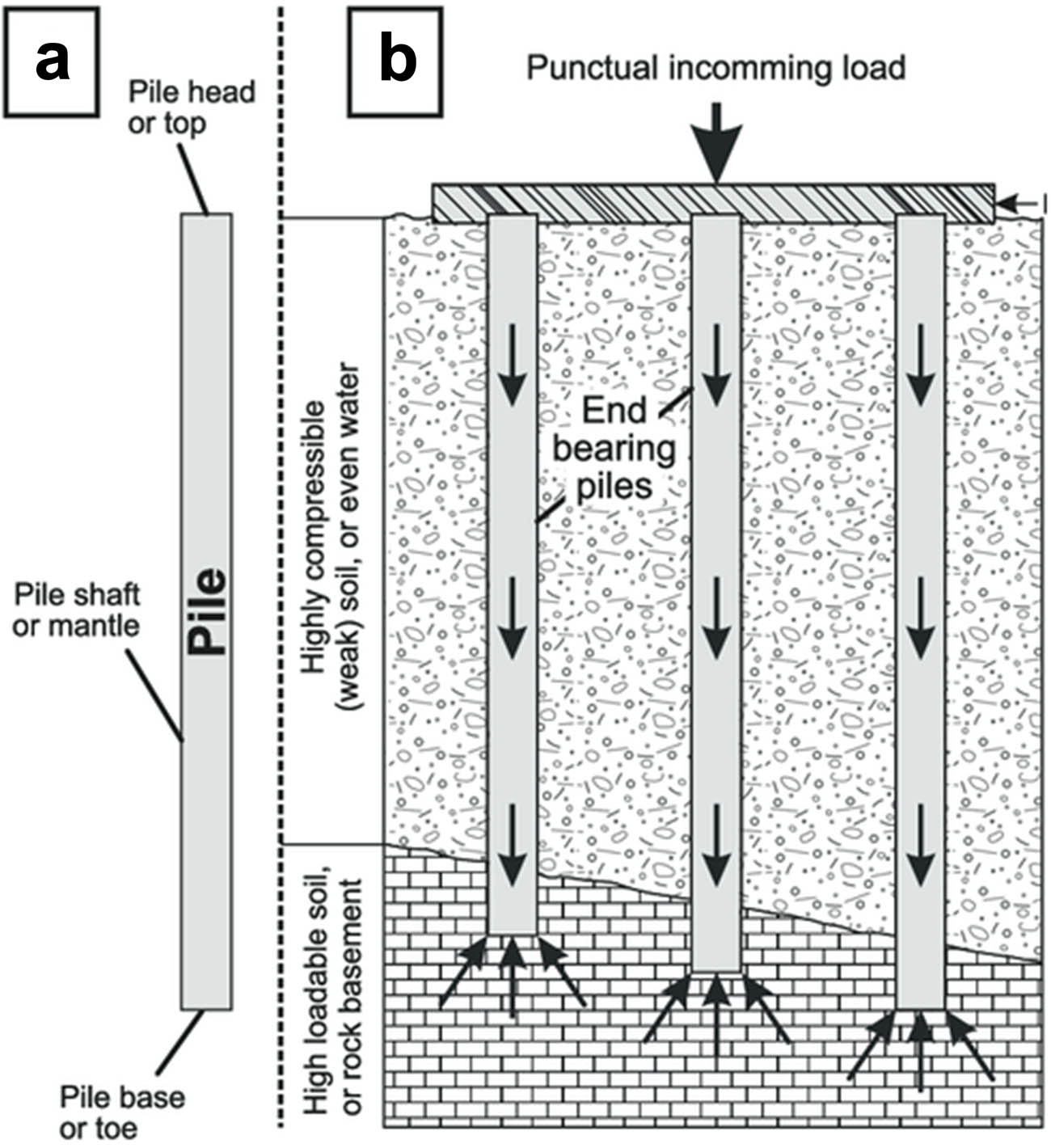
As a key form of deep foundation, pile foundation has been widely used in the engineering fields of buildings, bridges, wharves, and marine structures [1]. With the expansion of the project scale and the increasing complexity of the construction environment, the design and stability analysis of pile foundations are facing many challenges, especially in the marine and water environment, pile foundations need to withstand complex loads such as waves, tides, and earthquakes for a long period of time, so its stability has become one of the hotspots in civil engineering research [2,3].
The stability of pile foundation is mainly affected by soil–pile interaction, and this factor is crucial in the design process. The traditional static analysis method has some applicability under simple foundation conditions, but its prediction accuracy and safety are limited when facing complex geological environment and dynamic loading [4]. The non-uniformity and anisotropy of foundation soil and the dynamic interaction between pile and soil will affect the stability of pile foundation, so how to accurately assess the stability of pile foundation under complex foundation conditions has become the core issue of current research [5,6].
As computer technology and numerical calculation techniques advance, more and more studies are using numerical simulation tools to analyze the stability of pile foundations. The mechanical analysis of pile foundations has made extensive use of the finite element method (FEM), boundary element method, and discrete element method, which can simulate the pile force and take into account the pile–soil interaction to some degree [7,8]. However, when dealing with large-scale complex foundation problems, these methods still face challenges in computational accuracy and efficiency, which become the key difficulties in research.
At present, pile foundation stability analysis mostly focuses on static loading conditions, such as static analysis methods [9]. Although there are studies to explore the influence of dynamic loads such as wave load and earthquake load, most of them adopt simplified soil model, failing to fully consider the nonlinear and time-varying characteristics of the soil and the complex interactions between the pile and soil, which is difficult to comprehensively reflect the behavioral characteristics of the pile foundation under the actual working conditions, thus affecting its reliability and value of engineering applications [10].
This study addresses these limitations by proposing a numerical computation method based on a two-parameter model to thoroughly examine the effects of dynamic stresses – such as wave loads – on pile foundation stability [11]. Compared to the conventional Winkler model, the two-parameter model more effectively captures the nonlinear behavior of soil-pile interaction, thus enhancing the accuracy of the stability analysis [12]. The influence of key parameters, including pile water depth, lateral soil resistance coefficient, and pile stiffness, is systematically analyzed. An optimized analysis scheme that aligns more closely with actual engineering conditions is presented.
The main contributions of this study are twofold: first, it introduces an innovative methodology by replacing the traditional Winkler model with a two-parameter model, thereby improving the accuracy of stability prediction; second, it conducts an in-depth analysis of pile foundation stability under dynamic environmental conditions such as wave and tidal loads, offering valuable theoretical support for the design of offshore and deep-water pile foundations. The proposed method is validated through numerical and experimental comparisons, demonstrating promising application potential for enhancing the safety and reliability of pile foundation designs.
The structure of this study is organized as follows: Chapter 2 reviews relevant literature on pile foundation stability analysis. Chapter 3 introduces the theoretical background and modeling approach of the two-parameter method. Chapter 4 presents the numerical modeling and parameter sensitivity studies. Chapter 5 discusses the results and compares them with experimental data. Finally, Chapter 6 summarizes the main findings and suggests future research directions.
2 Analysis of pile skidding effect based on bending damage
Pile foundations not only bear vertical loads but also need to resist horizontal loads in complex geological environments, especially in the context of geologic hazards such as landslides and slope instability, and their anti-slip effect is crucial [13]. When subjected to horizontal loads, the pile body may undergo bending damage, and this damage mode has a direct impact on the slip resistance of the pile foundation. Therefore, it is of great significance to study the anti-slip effect of pile body based on bending damage to improve the stability and safety of pile foundation design.
2.1 Formation mechanism of pile bending damage
When the pile is subjected to horizontal loading, the soil–pile interaction leads to bending moments in the pile body and bending damage at specific parts of the pile. The damage is mainly affected by the following factors.
Different types of soil layers (e.g., soft soil, sandy soil, clay, etc.) have different lateral restraining effects on the pile body, which affects the bending pattern and damage mode of the pile body; static horizontal load, ground vibration load, wave load, etc., will induce different degrees of pile bending damage; Pile material and cross-section stiffness determine its bending resistance. Piles with lower stiffness are more likely to be bent when subjected to larger horizontal loads; the shear strength and compactness of the soil around the pile affect the deformation and bending damage of the pile.
2.2 Analysis of pile skid resistance effect
The anti-slip capacity of pile foundation mainly depends on the restraining effect of pile body in the direction of slip, and its anti-slip effect can be analyzed by the following aspects.
Stress distribution of pile body: In the process of slip resistance, the distribution of bending moment and shear force at different depths of pile body determines its slip resistance. Usually, the stress is concentrated at the top of the pile and the bending of the pile body, which is prone to plastic deformation or even damage; The soil body provides lateral support force to the pile body, which affects the slip resistance of the pile body. When the landslide force increases, the change in pile–soil interaction force determines whether the pile body can effectively prevent the landslide from occurring. In group pile structure, the interaction between adjacent piles enhances the overall skid resistance, but it may also lead to increased bending of the pile body due to the local damage of the soil between the piles; by adjusting the parameters of pile length, pile diameter, stiffness, and burial depth, the anti-slip performance of the pile body can be optimized to improve its bearing capacity and durability.
2.3 Numerical simulation and experimental validation
This study uses the FEM to create a model of the pile–soil interaction and simulate the deformation, stress distribution, and skidding resistance of the pile body under various operating conditions in order to thoroughly examine the skidding effect of the pile body under bending damage [14]. In order to examine the real skid resistance performance of the pile body and investigate the impact of various soil conditions, pile diameters, and load variations on the skid resistance effect, the numerical calculation results are simultaneously validated through physical model testing. Figure 1 displays the pile skid resistance analytical model.
Analytical model of pile skid resistance effect.
The pile sliding moment
where
The formula indicates that the slip-resisting moment of the pile body in the range of slip surface is determined by the integral of lateral earth pressure and force arm, which can be further modeled by specific earth pressure [15].
The mechanical equilibrium relationship for the skidding section of a pile subjected to horizontal net thrust (thrust minus resistance), vertical axial force, and bedding tension binding force can be expressed as follows:
where
Vertical force balance equation:
where N is the vertical axial force on the pile body (kN); W is the self-weight of pile body and additional load (kN); and
Moment balance equation (around a reference point O):
where
2.4 Pile bearing moment and ultimate net horizontal thrust
In cement fly-ash gravel (CFG) pile or concrete pile composite foundation, the pile body will produce bending moment when subjected to horizontal load, and the resulting tensile stress in the cross-section is often preceded by the compressive stress or shear strength to reach the limit, so that the bending damage is the dominant damage mode [16]. Bending damage not only affects the stability of single pile but also reduces the bearing capacity of the whole composite foundation system.
The bending damage of CFG piles is affected by several factors, including
CFG piles have a somewhat lower bending strength than conventional concrete piles and are often composed of a mixture of cement, fly ash, sand, and gravel. The pile body is vulnerable to bending damage when the tensile stress is above the limit when the bending moment is very great; piles with a smaller cross-section have a lower bending capacity and are more vulnerable to bending damage. The bending stiffness of the pile body is comparatively improved when the vertical load is large; however, if the load is too large, it may result in pile-soil contact surface slippage, which in turn affects the overall stability. This can be achieved by increasing the pile diameter or by optimizing the pile design. In the design of composite foundation, it is necessary to reasonably allocate the bearing proportion of pile and soil, in order to avoid local stress concentration leading to bending damage.
The stiffness and resistance of different soil layers affect the pile stress state. Weak soil layer may lead to insufficient pile lateral support, which increases the bending moment value and raises the risk of bending damage. In the composite foundation under embankment, the bending damage of CFG piles is mainly caused by the combined effect of the horizontal net thrust generated by the lateral slip of the foundation, the vertical axial force shared by the embankment load, and the binding force of the bedding reinforcement. Since the compressive strength of CFG piles is much larger than the tensile strength, its damage mode usually manifests itself as bending-tension damage, i.e., the bending and tensile stresses of the pile cross-section reach the limit [17].
In the force analysis, the maximum bending and tensile stresses σ
t
and the maximum bending and compressive stresses σ
c
in the pile cross-section under the joint action of the pile bearing moment
When σ t exceeds the tensile strength of the CFG pile, the pile body undergoes bending and tensile damage, a phenomenon that is particularly significant under soft ground or foundation conditions where lateral slip exists. Therefore, in the engineering design, it is necessary to optimize the cross-section size of the pile, reasonably distribute the load, and take measures to reduce the influence of the horizontal thrust on the pile in order to reduce the risk of bending damage.
When the pile slip section force is treated as a cantilever beam, the side-slip deformation of the composite foundation caused by the embankment filling causes the pile slip section to be subjected to the joint action of the horizontal net thrust of the soil between the piles, P h and the binding force of the bedding reinforcement on the top of the pile, T. In this case, the bending moment of the pile section at the potential slip surface, M s , can be expressed as
The formula shows that the horizontal thrust of soil between piles P h is mainly generated by the combination of lateral pressure of fill and lateral slip force of foundation, and its moment increases with the increase in the slip surface depth h s . The binding force of bedding reinforcement T at the top of pile produces negative bending moment on pile body.
The binding force of the top bedding reinforcement T produces a negative bending moment on the pile body, and its effect depends on the height of the action point h t and the strength of the reinforcement. The magnitude of bending moment determines whether the pile body undergoes bending damage or not. If M s is too large, it may lead to bending cracking or overall instability of the pile body near the slip surface.
When the bending moment
Since the ultimate bending moment M
i
of the pile body at the potential slip surface is generated by the net horizontal thrust
Combining the above equations gives the ultimate net horizontal thrust that the CFG pile can withstand
2.5 Pile-soil load sharing and pile bearing vertical axial force
In engineering practice, the pile body is not only subjected to horizontal thrust, but also to vertical load at the same time. Through the force analysis of the anti-slip section of the pile body, it can be seen that the compressive stress caused by the vertical load can partially offset the bending and tensile stress generated by the horizontal net thrust at the potential slip surface, thus improving the bending capacity and horizontal bearing capacity of the pile body, and enhancing the restraining effect of the pile body on the side-slip of the foundation.
Under the premise of ensuring the vertical bearing capacity of single pile, Hewlett’s method [18] is usually adopted to calculate the load
where
The load sharing ratio
In actual engineering application, the parameters should be adjusted according to specific foundation conditions and load distribution to ensure the safety and stability of the pile foundation system.
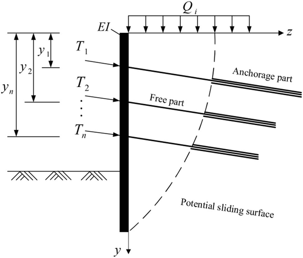
2.6 Horizontal binding force on pile top by bedding reinforcement
In a composite foundation system, bedding reinforcement (e.g., geogrids or reinforcing mesh) is able to provide additional horizontal restraining force by interacting with the fill, thereby enhancing the stability of the pile tops and limiting the lateral deformation of the foundation. The role of bedding reinforcement is mainly reflected in the following aspects.
Through its own tension action, the bedding tension bar shares the horizontal load with the embankment fill to reduce the horizontal deformation at the top of individual piles. The presence of tension bars spreads the horizontal thrust over a wider area and reduces the local stress concentration.
The bedding reinforcement is equivalent to applying a certain horizontal binding force T on the top of the pile, which is mainly affected by the tensile rigidity of the reinforcement
where T is the horizontal restraining force provided by the bedding reinforcement to the top of the pile (kN);
Distribution of bedding tendon strip tension extension.
Under the action of horizontal thrust, the binding force of the pile top reinforcement can effectively reduce the bending moment response of the pile body and improve the bending bearing capacity of the pile foundation system. When the role of the reinforcement is stronger, it can reduce the risk of bending and tension damage of the pile body and prolong the service life of the structure.
3 Stabilization factor for composite foundations
Under the action of flexible embankment fill load, the stress situation of CFG pile composite foundation is more complicated, and there is a significant asynchrony in the pile destruction process. At the outer edge of the foundation reinforcement area, the CFG piles in this area are the first to break due to ultimate bending damage because of the large lateral slip of the soil around the piles. The load of the damaged pile is then transferred to the neighboring piles, which triggers chain damage and may eventually lead to the overall instability of the whole foundation.
The circular arc strip division approach is used to do the overall stability study based on the approximate circular slip pattern of the composite foundation beneath the embankment. Because the slip surface’s undercut depth is greatest close to the circle’s center, the pile body there experiences a higher side-slide force. Damage from bending and tensile cracking will happen when the pile body’s cross-sectional bending and tensile stresses at the point tangent to the slip surface reach their maximum strength. Based on this, the pile body with the longest slip-resistant section of the composite foundation can be defined as the critical pile, i.e., the pile body with the first bending damage near the foot of the embankment slope, and accordingly, the determination criteria of two limit states can be established.
The bending and tensile stress of the key pile reaches the ultimate bending strength. The embankment as a whole is destabilized. Due to the asynchronous nature of pile failure, even if the critical piles reach the ultimate tensile strength, the piles at other locations may not be fully subjected to the ultimate bending moment.
In the foot of the slope area, the critical piles are subjected to a more special situation. Due to the small fill load in this area, the horizontal net pressure on the soil in the slip-resistant section of the pile is distributed in a triangular shape. The net horizontal pressure of the soil on the key pile at the slip surface is
The simulation analysis results show that the horizontal displacement of the composite foundation near the toe of the slope significantly increases compared to the symmetric location of the center of the roadbed and gradually increases from the center of the roadbed to the toe of the slope area. Therefore, it can be approximated to assume that the horizontal displacement of the foundation is zero at the center of the roadbed and grows along a linear trend to reach a maximum at the foot of the slope. Similarly, based on the numerical simulation analysis [19], the distribution characteristics of pile body shear force along the depth can be obtained, and the deduced horizontal net pressure
Horizontal thrust calculation model for the pile anti-slip portion.
When the CFG pile composite foundation under the embankment is in a critical state, the key pile near the foot of the slope undergoes bending and tensile damage near the potential slip surface. Based on Eq. (13), the ultimate horizontal net thrust
In order to characterize the asynchrony of the bending and pulling damage process of the pile in the composite foundation, the ratio of the pile-bearing horizontal net thrust
This coefficient is used to characterize the relative differences in the slip resistance of different piles during the stressing process, reflecting their asynchrony in the bending and tension damage process.
This coefficient is used to characterize the relative differences in the slip resistance of different piles during the stressing process, reflecting their asynchrony in the bending and tension damage process.
4 Experiments
4.1 Calculation of unsteady loads
When analyzing the unsteady load of the pile under harmonic loading, the corresponding formula can be derived by adjusting the amplitude. Therefore, in this paper, under the ideal assumption of Case 3, the unsteady load formula is converted by splitting the formula, and the weld is split based on the same constraints in the other three cases to ensure the accuracy of the corresponding unsteady load calculation.
Accurately capturing the dynamic reaction of the pile body under various weights is crucial for modifying the equations under various working situations. We can guarantee that the calculation of the unstable load has a high degree of accuracy and practicability by equitably allocating the effects and transformations of the loads. Additionally, the load fluctuations under various situations must be assessed through appropriate modeling and analysis, taking into account the material attributes and structural complexity.
In this context, the calculation of unsteady loads involves the variation in amplitude with the conversion of loads under different operating conditions. In order to simplify the expression, a sample equation is given below to show the basic framework of unstable load calculation. It is assumed that the unstable load
where
Adjustment formula for weld impact:
where
With the above equations, the amplitude variation, weld influence, and other factors can be combined for the calculation of unstable loads.
4.2 Analysis of destabilizing loads in relation to key parameters
Figure 4 shows the relationship between the instability load
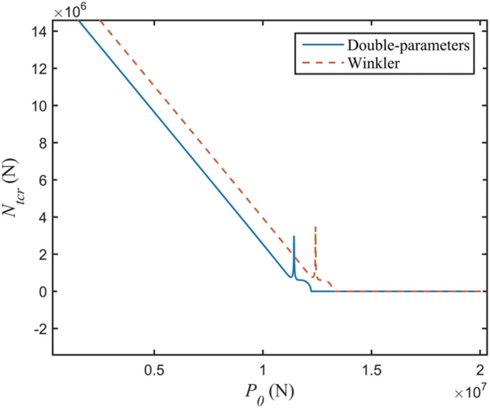
The effect of static load P 0 at the top of the pile on the destabilizing load.
Furthermore, the instability loads determined by the Winkler model and the two-parameter model are contrasted in Figure 5. The findings demonstrate that the instability load determined by the two-parameter model is comparatively lower. This suggests that the shear impact weakens the soil constraint surrounding the pile and decreases soil stiffness, which in turn affects the instability load calculation. This fact suggests that in real-world engineering applications, the two-parameter model is safer and more dependable.

Impact of pile stiffness capacity load
4.3 Connection between destabilizing load and pile depth
The impact of pile depth h on the destabilizing load is seen in Figure 6. The destabilizing load exhibits a sharp declining trend as h increases, followed by a steady slowdown and eventual stabilization of the lowering rate. Actually, the impact of wave scour on the foundation is reflected in the variation in pile depth. Continuous wave action causes the soil on the pile side to gradually disappear under conditions of constant water depth. This weakens the lateral constraint force and increases the pile body’s free length, which in turn causes the instability load to diminish. The two-parameter model’s rationality and practical relevance are further confirmed by the fact that, when comparing the two models’ findings, the instability loads it produced were lower than those of the Winkler model.
Lateral coefficient k of foundation soil on unstable situation urban load.
Figure 6 illustrates the relationship between pile depth h and the corresponding destabilizing load under dynamic conditions. As shown in the figure, the destabilizing load decreases significantly with increasing pile depth at the initial stage, indicating a high sensitivity of pile stability to wave-induced scour effects. This rapid reduction reflects the substantial weakening of lateral soil support as scour increases the effective free length of the pile.
As the depth h continues to increase, the declining trend in destabilizing load slows and eventually tends toward stabilization. This implies that beyond a certain point, further scour has a diminishing effect on the reduction in pile stability, likely because the soil-pile interaction reaches a critical lower bound where lateral resistance becomes minimal.
The comparison between the two-parameter model and the traditional Winkler model in this figure highlights a key finding: the instability loads predicted by the two-parameter model are consistently lower. This suggests that the two-parameter model more accurately captures the degradation of lateral resistance and pile–soil interaction under scour conditions, thereby offering a more conservative and realistic estimate of pile performance under dynamic marine environments.
4.4 Impact of the pile-side horizontal resistance coefficient kk on destabilizing loads
Figure 7 shows the trend of destabilizing loads with different horizontal resistance coefficients k on the pile side. When k is small,
3-D image of displacement vs
4.5 Relationship between pile displacement u and instability load
N
t
From the figure, it can be seen that the displacement curve has a sudden change in some areas, and the corresponding
The critical load frequency of the system is Ω, according to the analysis of frequency impacting factors. First, we examine how the Winkler model and the two-parameter model affect the crucial frequency computation. The graph showing how the load frequency change affects the amplitude in Case 3 is shown in Figure 8. It is evident from the graph that when the load frequency rises, the amplitude changes significantly. The parametric resonant frequency of the system is the equivalent load frequency when the amplitude reaches its maximum value.
Critical frequency comparison between two-parameter.
The damping effect causes the amplitude to fluctuate sharply in the range near the parametric resonance frequency rather than tending to infinity when the load frequency is near that frequency. The amplitude’s sharp rise and fall trend in the parametric resonance frequency range close to |δ|, the unstable zone of pile vibration, is shown in Figure 8. The critical frequency derived from the two-parameter model is less than the Winkler model’s computed value, according to a comparison of the two curves’ computation results.
In addition, Figure 9 demonstrates the characteristics of the system’s displacement with time and frequency in three dimensions, allowing for a more intuitive distribution of the unstable region. This figure further validates the difference in critical frequency under different models and provides a deeper understanding of the dynamic response characteristics of the system.
Displacement u as a function of time t and load frequency.
Figure 9 shows the displacement response of the system under different loading frequencies and times in a three-dimensional way, which visually depicts the dynamic response characteristics of the pile foundation under cyclic dynamic loading. In the figure, it is obvious that the displacement response amplitude of certain frequency regions increases significantly, forming “peak zone” or “high response zone,” which are the frequency ranges where the system may be destabilized.
4.6 Impact of shear stiffness and soil coefficient k on the pile’s side
The impact of shear stiffness G and coefficient k on the pile lateral soil and its mechanism on the critical frequency are the main topics of this section. We discovered in the previous load instability analysis that the critical frequency is significantly impacted by the pile lateral soil’s resistance coefficient, k. In order to identify its action mechanism, we further examine its influence pattern in this part.
The curve in Figure 10 illustrates that the impact of mass mm on the critical frequency is opposite to that of k. In particular, the crucial frequency progressively rises as k increases, although the increase tends to diminish. Furthermore, Figure 10 shows a curve interval close to zero. According to the research, this is because the soil constraint is weak when k is small, which causes the pile to become unstable under wave and vertical loads and causes the curve to exhibit an interval of zero close to horizontal. The soil constraint on the pile side rises as kk increases further, raising the critical frequency. It is important to note that the figure’s comparison of the two curves confirms the two-parameter method’s superiority in this particular case.
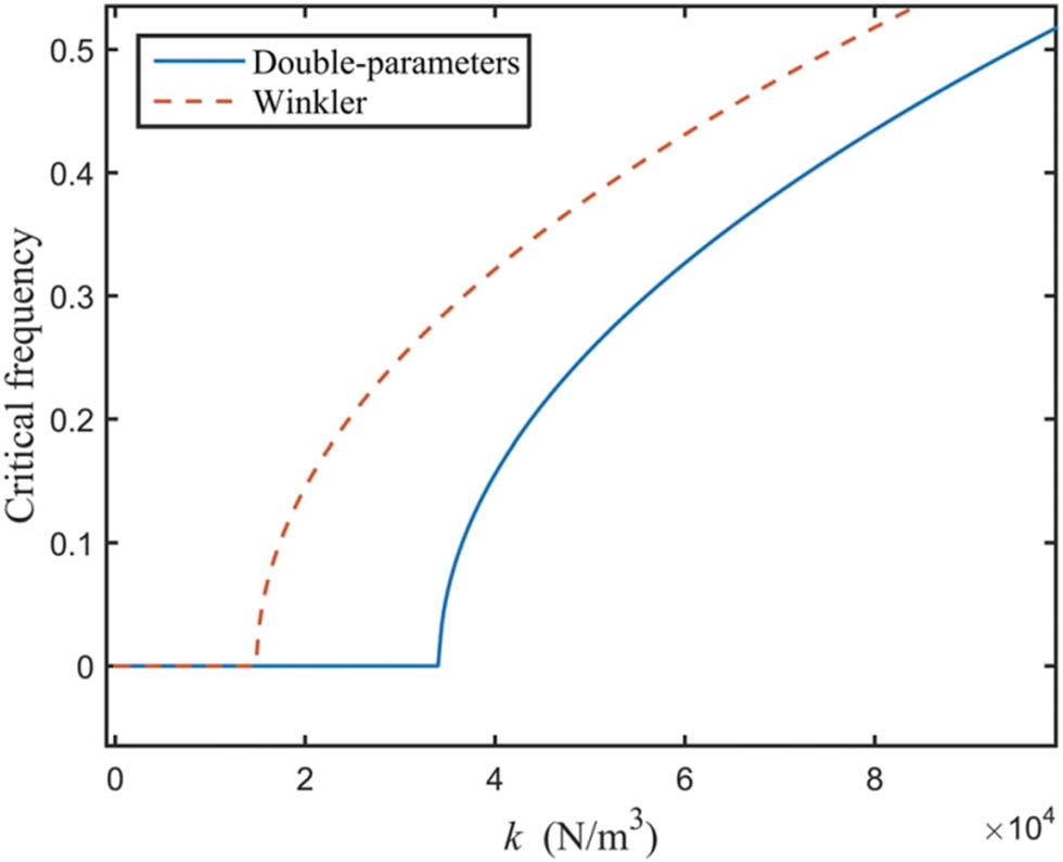
Effect of soil parameter k on the critical frequency.
Figure 11 shows how shear stiffness G affects the critical frequency. According to the chart, the crucial frequency decreases as G increases. It is clear from comparing Figures 10 and 11 that, in the same conditions, the soil resistance coefficient k has a greater effect on the critical frequency than does shear stiffness G. This suggests that dirt on the pile’s side is necessary to increase its stability since it may effectively boost the critical frequency and lessen the instability caused by the loading in addition to helping the pile’s lateral restraining ability. Practical engineering applications must consider the effect of surrounding soil on pile stability and put effective measures in place to prevent erosion and soil loosening on the pile’s side due to wave loading in order to ensure the long-term stability of the pile foundation structure.
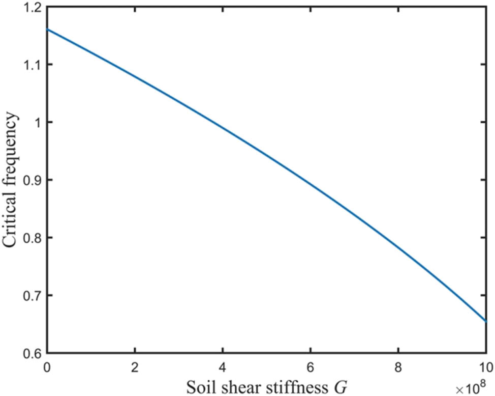
The relationship between critical frequency and soil stiffness G.
In the previous part of the study, we have demonstrated the effect of pile-side soil on pile stability. Since the pile foundation in the marine environment is subjected to wave loading for a long time, part of the soil around it is susceptible to erosion and scouring, leading to the gradual loss of soil on the pile side. With the loss of soil, the free length of the pile increases, which makes the restraining effect of the soil on the pile side weaken, thus affecting its critical frequency.
Specifically, the trend of critical frequency is shown in Figure 12. The figure shows that the critical frequency decreases nonlinearly with the increase in the h/l ratio (the ratio of the free length of the pile to the total length) and falls below 0.5 when the h/l exceeds a certain threshold. In this state, the critical frequency is close to the frequency of wave loading, which increases the possibility of parametric resonance. This resonance effect may cause fatigue damage to the pile body and even lead to structural instability, thus significantly reducing the long-term service performance of the pile foundation.
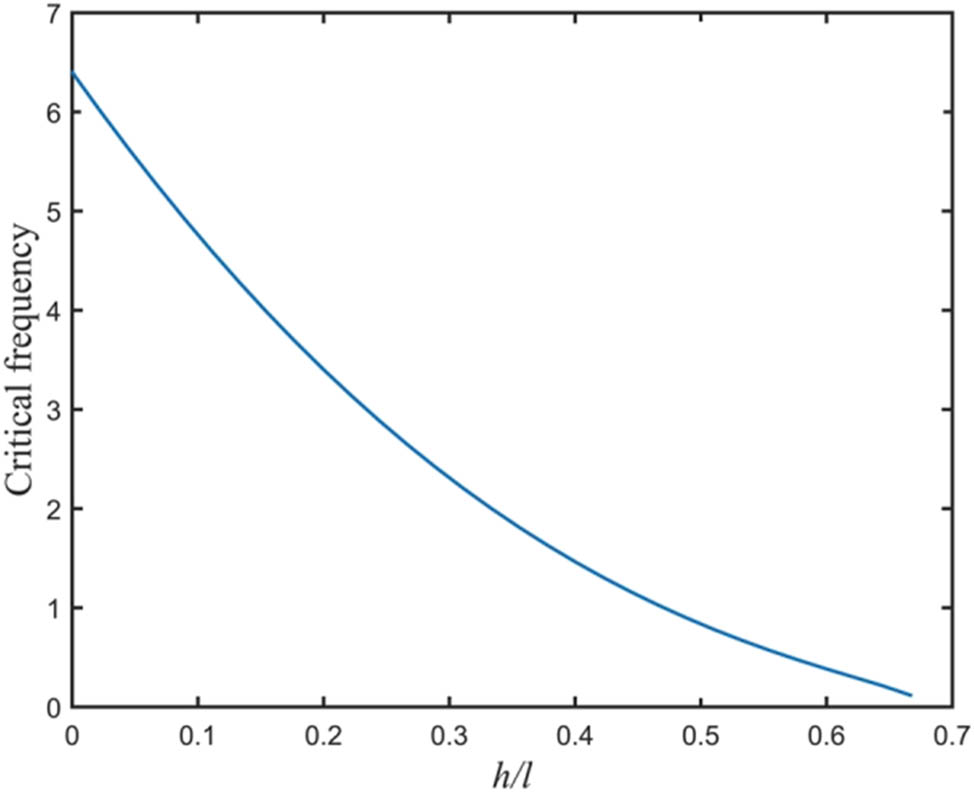
The impact of the ratio of pile length h to pile body length h in water length of critical frequency pile l.
In order to slow down soil loss and improve the restraining ability of the soil on the pile’s side, practical engineering applications must implement effective protective measures. These measures include optimizing the soil protection structure around the pile, increasing the scour prevention device, or adopting high-strength composite materials. This will improve the resonance resistance of the pile foundation structure, reduce the decrease in the critical frequency, and improve the structure’s long-term stability and safety in the marine environment.
4.7 How pile diameter (d) and length (l) affect critical frequency
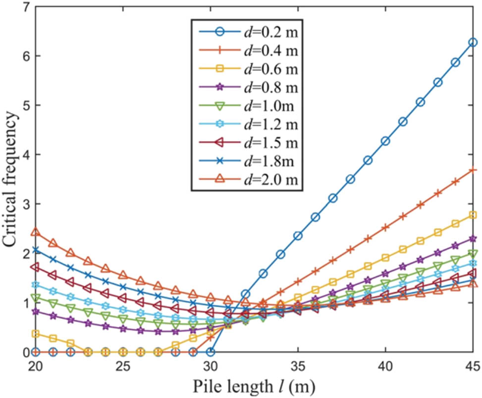
The impact of increasing pile length on critical frequency is the main topic of this section. While the free length of the pile exposed to the earth stays the same, the increase in pile length in this instance relates to the depth of the pile foundation submerged in the seabed. An intriguing phenomenon is revealed by Figure 14, which shows how pile length l affects the critical frequency. Unlike what was initially thought, the critical frequency does not decrease steadily as pile length increases; rather, it begins to increase as pile length increases beyond a certain point.
The study demonstrates that the alteration of the soil constraint effect is directly linked to the phenomenon’s cause. The crucial frequency gradually drops when the pile length is minimal because the buried soil layer is shallow and the soil’s restraining impact on the pile is weak. At this point, though, it is easier to see how increasing pile length reduces the critical frequency. The constraint of the soil on the pile side increases as the pile moves deeper into the soil layer. When the pile length reaches a certain equilibrium point, the restriction of the soil to the pile tends to stabilize and the critical frequency no longer drops significantly. The crucial frequency rises as the pile length increases because the soil’s restraining impact keeps growing.
Moreover, Figure 15 illustrates how pile dimension dd affects the critical frequency. In the first half of the curve, a larger pile diameter is linked to a higher critical frequency, whereas in the second half, a smaller pile diameter is linked to a lower critical frequency. As demonstrated by the earlier study, an increase in mass significantly reduces the critical frequency for the same pile length, which is why a greater pile diameter denotes a larger mass. Therefore, pile length and pile diameter must be carefully determined in the pile foundation design in order to control the critical frequency away from the loading frequency and avoid the instability risk caused by parametric resonance.
The critical frequency may decrease to zero as the pile length increases when the pile diameter d is small, indicating that the pile has entered the unstable state. This phenomenon suggests that if the pile’s length to diameter ratio is too high, the pile may become unstable from its own weight. In order to guarantee structural stability, the length-to-diameter ratio of the pile should be suitably optimized in the actual project based on the particular working conditions. Appropriate steps should also be taken to increase the pile foundation’s resonance resistance in order to improve overall durability and safety.
Figure 12 shows the influence of the ratio of the depth of pile entry to the total length of the pile on the critical frequency.
The figure demonstrates that under the condition of constant free length of pile body, the critical frequency decreases and then increases with the increase in total length of pile body. It shows that the effect of pile length on the critical frequency is closely related to the soil constraint, when the pile is buried at a shallow depth, the constraint is weak and the critical frequency decreases, while when the pile is deepened to a certain depth, the soil constraint is strengthened and the critical frequency rises instead.
Figure 13 shows the joint effect of pile diameter d and pile length l on critical frequency. The figure shows that the critical frequency may drop to zero with the increase in pile length when the pile diameter is small, suggesting that the pile may be destabilized due to self-weight, and a reasonable length-to-diameter ratio needs to be controlled; whereas, when the pile diameter is large, the critical frequency rises and then decreases in spite of the increase in the mass, and the mass needs to be balanced with the stability.
The impact of pile diameter (d) and length (l) on the critical value.
Figure 14 shows the effect of pile-soil stiffness ratio on amplitude, which illustrates that an increase in the pile-soil stiffness ratio decreases the vibration response amplitude, implying that an increase in the soil confinement capacity or pile stiffness helps to improve the vibration resistance of the structure and enhances the resistance of the system to dynamic loading.
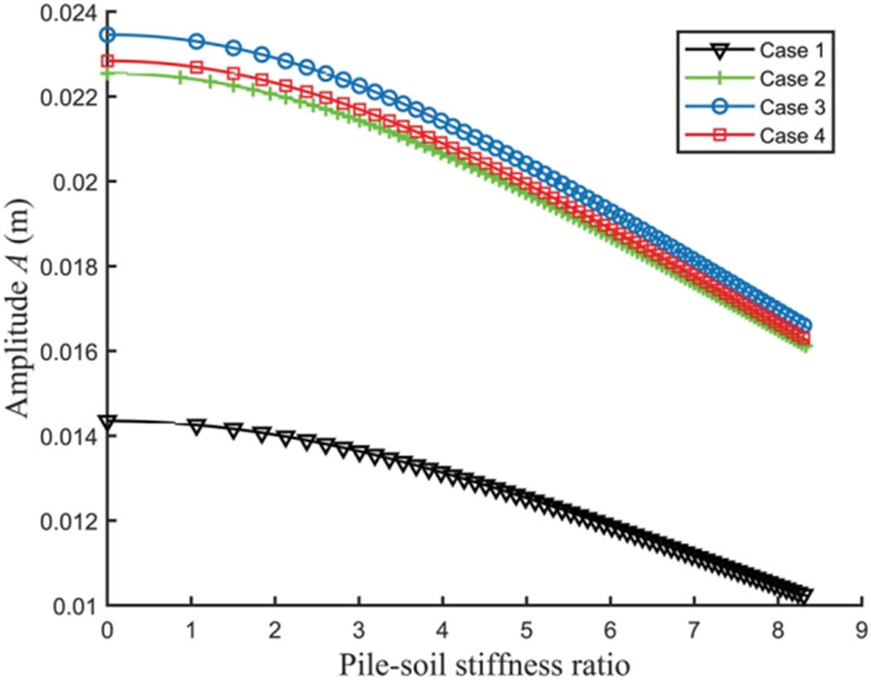
Effect of pile-soil stiffness ratio on amplitude.
Figure 15 demonstrates that the amplitude varies nonlinearly with the pile diameter. In the initial stage, as the pile diameter increases, the amplitude decreases, indicating improved vibration resistance. However, beyond a certain point, further increases in pile diameter lead to a rise in amplitude. This suggests that the self-weight of the pile has a significant impact on its vibration characteristics. Therefore, in structural design, it is essential to balance the benefits of increased stiffness with the adverse effects of added self-weight.
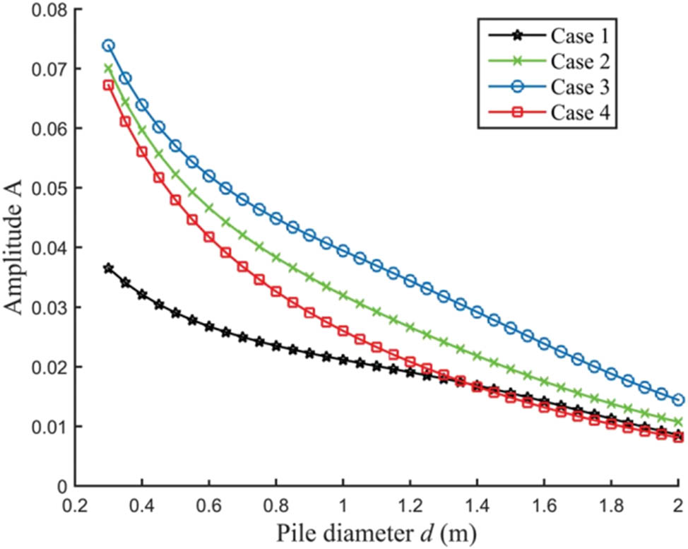
Amplitude as a function of pile diameter d.
5 Conclusion
This work proposes a numerical calculation method based on a two-parameter model for analyzing the stability of pile foundations under complex foundation conditions. By considering dynamic loads and soil nonlinearity, the model accurately reflects the influence of key parameters such as pile water entry depth, soil resistance, and pile stiffness. Compared with the traditional Winkler model, the two-parameter model demonstrates higher precision in predicting critical and destabilizing loads, especially under dynamic loading.
However, further validation is needed to assess its effectiveness in real engineering applications, particularly under extreme conditions. Future studies may incorporate more complex soil behaviors and loading types to enhance the model’s generality and engineering applicability.
-
Funding information: This study is supported by Natural Science Research Project of Colleges and Universities of Jiangsu Province (22KJD560007). Jiangsu Province Industry-university-research Cooperation Project: (BY20231049, BY20231095).
-
Author contributions: The authors confirm contribution to the article as follows: study conception and design: Huimin Wang and Jing Zhang; data collection: Kai Zhang; analysis and interpretation of results: Jing Zhang and Kaiqing Ma; draft manuscript preparation: Huimin Wang and Kaiqing Ma. All authors reviewed the results and approved the final version of the manuscript. All authors have accepted responsibility for the entire content of this manuscript and approved its submission.
-
Conflict of interest: Authors state no conflict of interest.
-
Data availability statement: The datasets generated during and/or analyzed during the current study are available from the corresponding author on reasonable request.
References
[1] Yin X, Ni H. Displacement analysis and numerical simulation of pile-anchor retaining structure in deep foundation pit. J Meas Eng. 2024;12(1):124–37.10.21595/jme.2023.23635Suche in Google Scholar
[2] Li D, Yi F, Li X, Chen S, Hu Z, Liu J. Excavation effects on reinforced concrete pile foundations: a numerical analysis. Buildings. 2024;14(4):995.10.3390/buildings14040995Suche in Google Scholar
[3] Han M, Jia J, Li Z, Zhu Z, Tu B, Liu L. Improved analytical method for stabilizing piles in loess slope considering nonlinear pile–soil interactions. Int J Geomech. 2024;24(3):04024002.10.1061/IJGNAI.GMENG-8796Suche in Google Scholar
[4] Sheng M, Lu F, Jiang N, Guo P, Li X, An R, et al. Bearing behavior of pile foundation in karst region: Physical model test and finite element analysis. Appl Rheol. 2024;34(1):20230115.10.1515/arh-2023-0115Suche in Google Scholar
[5] Xu Q, Xie J, Lu L, Wang Y, Wu C, Meng Q. Numerical and theoretical analysis on soil arching effect of prefabricated piles as deep foundation pit supports. Undergr Space. 2024;16:314–30.10.1016/j.undsp.2023.09.011Suche in Google Scholar
[6] Xie B, Sun H, Liu T, Tan H. Investigation of the local scour depth of a pile foundation on the migrating sand waves seabed in the western South China Sea. Front Earth Sci. 2024;12:1404430.10.3389/feart.2024.1404430Suche in Google Scholar
[7] Cao MM, Ma SJ, Zhang JW. Numerical analysis study on the influence of shield cutting pile on the settlement of pile–soil composite foundation. Adv Civ Eng. 2024;2024(1):5345820.10.1155/2024/5345820Suche in Google Scholar
[8] Wen Z, Xu W, Yuan B, Zhang L, Liang Z. Numerical analysis of anti-slide pile reinforcement for slope stability under rainfall conditions. Buildings. 2025;15(4):638.10.3390/buildings15040638Suche in Google Scholar
[9] Shen K, Zhang H, Liu J, Zhao X, Zhang Y. Study of cement-soil mixed piles reinforcement method for offshore wind turbine pile foundation. Ocean Eng. 2024;313:119423.10.1016/j.oceaneng.2024.119423Suche in Google Scholar
[10] Liu T, Liu Z, Ma C, Xu Z, Yu L, Zhang X, et al. A numerical analysis of the role of pile foundations in shaft sinking using the vertical shaft sinking machine (VSM). Buildings (2075-5309). 2024;14(11):3383.10.3390/buildings14113383Suche in Google Scholar
[11] Li J, Hou H, Li Z, Lin G. A novel hybrid framework based on modified continued-fraction for pile-soil dynamic interaction of large-scale nuclear power structures. Comput Geotech. 2024;173:106571.10.1016/j.compgeo.2024.106571Suche in Google Scholar
[12] Xu Q, Zhou X, Liu X, Yang G, Xu B, Tu Y. Mechanism of structural defects in cut-and-cover tunnels within high-fill regions and gradient pile foundation reinforcement technology. Tunn Undergr Space Technol. 2024;154:106123.10.1016/j.tust.2024.106123Suche in Google Scholar
[13] Hasan MM, Hore S, Al Alim M, Hore R, Ansary MA. Numerical modeling of seismic soil-pile-structure interaction (SSPSI) effects on tall buildings with pile mat foundation. Arab J Geosci. 2025;18(1):1–14.10.1007/s12517-024-12155-4Suche in Google Scholar
[14] Qu Z, Han Z, Tang H, Xu J, Wang H, Liu Y. Study on numerical simulation of arch mechanism of bridge pile foundation. Buildings. 2024;14(1):146.10.3390/buildings14010146Suche in Google Scholar
[15] Zhao Z, Zhang H, Shiau J, Du W, Ke L, Wu F, et al. Failure envelopes of rigid tripod pile foundation under combined vertical-horizontal-moment loadings in clay. Appl Ocean Res. 2024;150:104131.10.1016/j.apor.2024.104131Suche in Google Scholar
[16] Li X, Zhang X, Zhang F, Huang J, Tang S, Liu Z. A case study for stability analysis of a toppling bank slope with fault fracture zones developed under the action of bridge loads and reservoir water. Water. 2024;16(3):494.10.3390/w16030494Suche in Google Scholar
[17] Gao Y, Zhang Y, Xie Q, Liu Q, Liu T, You T, et al. A study on the influence of anchor rods’ layout on the uplift resistance characteristics of inclined anchor short-pile foundations based on FEA. Buildings. 2024;14(8):2580.10.3390/buildings14082580Suche in Google Scholar
[18] Wu R, Jiang Y, Zhao S, Chen M, Shang S, Lang X. Application and comparative analysis of intelligent monitoring technology for grouted pile construction based on Abaqus. Sci Rep. 2024;14(1):9253.10.1038/s41598-024-59653-9Suche in Google Scholar PubMed PubMed Central
[19] Sun M, Shan Z, Wang W, Xu S, Liu X, Zhang H, et al. Numerical investigation into the stability of offshore wind power piles subjected to lateral loads in extreme environments. J Mar Sci Eng. 2024;12(6):915.10.3390/jmse12060915Suche in Google Scholar
© 2025 the author(s), published by De Gruyter
This work is licensed under the Creative Commons Attribution 4.0 International License.
Artikel in diesem Heft
- Research Articles
- Generalized (ψ,φ)-contraction to investigate Volterra integral inclusions and fractal fractional PDEs in super-metric space with numerical experiments
- Solitons in ultrasound imaging: Exploring applications and enhancements via the Westervelt equation
- Stochastic improved Simpson for solving nonlinear fractional-order systems using product integration rules
- Exploring dynamical features like bifurcation assessment, sensitivity visualization, and solitary wave solutions of the integrable Akbota equation
- Research on surface defect detection method and optimization of paper-plastic composite bag based on improved combined segmentation algorithm
- Impact the sulphur content in Iraqi crude oil on the mechanical properties and corrosion behaviour of carbon steel in various types of API 5L pipelines and ASTM 106 grade B
- Unravelling quiescent optical solitons: An exploration of the complex Ginzburg–Landau equation with nonlinear chromatic dispersion and self-phase modulation
- Perturbation-iteration approach for fractional-order logistic differential equations
- Variational formulations for the Euler and Navier–Stokes systems in fluid mechanics and related models
- Rotor response to unbalanced load and system performance considering variable bearing profile
- DeepFowl: Disease prediction from chicken excreta images using deep learning
- Channel flow of Ellis fluid due to cilia motion
- A case study of fractional-order varicella virus model to nonlinear dynamics strategy for control and prevalence
- Multi-point estimation weldment recognition and estimation of pose with data-driven robotics design
- Analysis of Hall current and nonuniform heating effects on magneto-convection between vertically aligned plates under the influence of electric and magnetic fields
- A comparative study on residual power series method and differential transform method through the time-fractional telegraph equation
- Insights from the nonlinear Schrödinger–Hirota equation with chromatic dispersion: Dynamics in fiber–optic communication
- Mathematical analysis of Jeffrey ferrofluid on stretching surface with the Darcy–Forchheimer model
- Exploring the interaction between lump, stripe and double-stripe, and periodic wave solutions of the Konopelchenko–Dubrovsky–Kaup–Kupershmidt system
- Computational investigation of tuberculosis and HIV/AIDS co-infection in fuzzy environment
- Signature verification by geometry and image processing
- Theoretical and numerical approach for quantifying sensitivity to system parameters of nonlinear systems
- Chaotic behaviors, stability, and solitary wave propagations of M-fractional LWE equation in magneto-electro-elastic circular rod
- Dynamic analysis and optimization of syphilis spread: Simulations, integrating treatment and public health interventions
- Visco-thermoelastic rectangular plate under uniform loading: A study of deflection
- Threshold dynamics and optimal control of an epidemiological smoking model
- Numerical computational model for an unsteady hybrid nanofluid flow in a porous medium past an MHD rotating sheet
- Regression prediction model of fabric brightness based on light and shadow reconstruction of layered images
- Dynamics and prevention of gemini virus infection in red chili crops studied with generalized fractional operator: Analysis and modeling
- Qualitative analysis on existence and stability of nonlinear fractional dynamic equations on time scales
- Review Article
- Haar wavelet collocation method for existence and numerical solutions of fourth-order integro-differential equations with bounded coefficients
- Special Issue: Nonlinear Analysis and Design of Communication Networks for IoT Applications - Part II
- Silicon-based all-optical wavelength converter for on-chip optical interconnection
- Research on a path-tracking control system of unmanned rollers based on an optimization algorithm and real-time feedback
- Analysis of the sports action recognition model based on the LSTM recurrent neural network
- Industrial robot trajectory error compensation based on enhanced transfer convolutional neural networks
- Research on IoT network performance prediction model of power grid warehouse based on nonlinear GA-BP neural network
- Interactive recommendation of social network communication between cities based on GNN and user preferences
- Application of improved P-BEM in time varying channel prediction in 5G high-speed mobile communication system
- Construction of a BIM smart building collaborative design model combining the Internet of Things
- Optimizing malicious website prediction: An advanced XGBoost-based machine learning model
- Economic operation analysis of the power grid combining communication network and distributed optimization algorithm
- Sports video temporal action detection technology based on an improved MSST algorithm
- Internet of things data security and privacy protection based on improved federated learning
- Enterprise power emission reduction technology based on the LSTM–SVM model
- Construction of multi-style face models based on artistic image generation algorithms
- Special Issue: Decision and Control in Nonlinear Systems - Part II
- Animation video frame prediction based on ConvGRU fine-grained synthesis flow
- Application of GGNN inference propagation model for martial art intensity evaluation
- Benefit evaluation of building energy-saving renovation projects based on BWM weighting method
- Deep neural network application in real-time economic dispatch and frequency control of microgrids
- Real-time force/position control of soft growing robots: A data-driven model predictive approach
- Mechanical product design and manufacturing system based on CNN and server optimization algorithm
- Application of finite element analysis in the formal analysis of ancient architectural plaque section
- Research on territorial spatial planning based on data mining and geographic information visualization
- Fault diagnosis of agricultural sprinkler irrigation machinery equipment based on machine vision
- Closure technology of large span steel truss arch bridge with temporarily fixed edge supports
- Intelligent accounting question-answering robot based on a large language model and knowledge graph
- Analysis of manufacturing and retailer blockchain decision based on resource recyclability
- Flexible manufacturing workshop mechanical processing and product scheduling algorithm based on MES
- Exploration of indoor environment perception and design model based on virtual reality technology
- Tennis automatic ball-picking robot based on image object detection and positioning technology
- A new CNN deep learning model for computer-intelligent color matching
- Design of AR-based general computer technology experiment demonstration platform
- Indoor environment monitoring method based on the fusion of audio recognition and video patrol features
- Health condition prediction method of the computer numerical control machine tool parts by ensembling digital twins and improved LSTM networks
- Establishment of a green degree evaluation model for wall materials based on lifecycle
- Quantitative evaluation of college music teaching pronunciation based on nonlinear feature extraction
- Multi-index nonlinear robust virtual synchronous generator control method for microgrid inverters
- Manufacturing engineering production line scheduling management technology integrating availability constraints and heuristic rules
- Analysis of digital intelligent financial audit system based on improved BiLSTM neural network
- Attention community discovery model applied to complex network information analysis
- A neural collaborative filtering recommendation algorithm based on attention mechanism and contrastive learning
- Rehabilitation training method for motor dysfunction based on video stream matching
- Research on façade design for cold-region buildings based on artificial neural networks and parametric modeling techniques
- Intelligent implementation of muscle strain identification algorithm in Mi health exercise induced waist muscle strain
- Optimization design of urban rainwater and flood drainage system based on SWMM
- Improved GA for construction progress and cost management in construction projects
- Evaluation and prediction of SVM parameters in engineering cost based on random forest hybrid optimization
- Museum intelligent warning system based on wireless data module
- Special Issue: Nonlinear Engineering’s significance in Materials Science
- Experimental research on the degradation of chemical industrial wastewater by combined hydrodynamic cavitation based on nonlinear dynamic model
- Study on low-cycle fatigue life of nickel-based superalloy GH4586 at various temperatures
- Some results of solutions to neutral stochastic functional operator-differential equations
- Ultrasonic cavitation did not occur in high-pressure CO2 liquid
- Research on the performance of a novel type of cemented filler material for coal mine opening and filling
- Testing of recycled fine aggregate concrete’s mechanical properties using recycled fine aggregate concrete and research on technology for highway construction
- A modified fuzzy TOPSIS approach for the condition assessment of existing bridges
- Nonlinear structural and vibration analysis of straddle monorail pantograph under random excitations
- Achieving high efficiency and stability in blue OLEDs: Role of wide-gap hosts and emitter interactions
- Construction of teaching quality evaluation model of online dance teaching course based on improved PSO-BPNN
- Enhanced electrical conductivity and electromagnetic shielding properties of multi-component polymer/graphite nanocomposites prepared by solid-state shear milling
- Optimization of thermal characteristics of buried composite phase-change energy storage walls based on nonlinear engineering methods
- A higher-performance big data-based movie recommendation system
- Nonlinear impact of minimum wage on labor employment in China
- Nonlinear comprehensive evaluation method based on information entropy and discrimination optimization
- Application of numerical calculation methods in stability analysis of pile foundation under complex foundation conditions
- Research on the contribution of shale gas development and utilization in Sichuan Province to carbon peak based on the PSA process
- Characteristics of tight oil reservoirs and their impact on seepage flow from a nonlinear engineering perspective
- Nonlinear deformation decomposition and mode identification of plane structures via orthogonal theory
- Numerical simulation of damage mechanism in rock with cracks impacted by self-excited pulsed jet based on SPH-FEM coupling method: The perspective of nonlinear engineering and materials science
- Cross-scale modeling and collaborative optimization of ethanol-catalyzed coupling to produce C4 olefins: Nonlinear modeling and collaborative optimization strategies
- Unequal width T-node stress concentration factor analysis of stiffened rectangular steel pipe concrete
- Special Issue: Advances in Nonlinear Dynamics and Control
- Development of a cognitive blood glucose–insulin control strategy design for a nonlinear diabetic patient model
- Big data-based optimized model of building design in the context of rural revitalization
- Multi-UAV assisted air-to-ground data collection for ground sensors with unknown positions
- Design of urban and rural elderly care public areas integrating person-environment fit theory
- Application of lossless signal transmission technology in piano timbre recognition
- Application of improved GA in optimizing rural tourism routes
- Architectural animation generation system based on AL-GAN algorithm
- Advanced sentiment analysis in online shopping: Implementing LSTM models analyzing E-commerce user sentiments
- Intelligent recommendation algorithm for piano tracks based on the CNN model
- Visualization of large-scale user association feature data based on a nonlinear dimensionality reduction method
- Low-carbon economic optimization of microgrid clusters based on an energy interaction operation strategy
- Optimization effect of video data extraction and search based on Faster-RCNN hybrid model on intelligent information systems
- Construction of image segmentation system combining TC and swarm intelligence algorithm
- Particle swarm optimization and fuzzy C-means clustering algorithm for the adhesive layer defect detection
- Optimization of student learning status by instructional intervention decision-making techniques incorporating reinforcement learning
- Fuzzy model-based stabilization control and state estimation of nonlinear systems
- Optimization of distribution network scheduling based on BA and photovoltaic uncertainty
- Tai Chi movement segmentation and recognition on the grounds of multi-sensor data fusion and the DBSCAN algorithm