Progressive collapse performance of shear strengthened RC frames by nano CFRP
-
Weihong Chen
 ,
Jinwen Zhang
,
Jinwen Zhang

Abstract
To investigate the effect of nano carbon-fiber-reinforced polymer (nano CFRP) on retrofitting reinforced concrete (RC) structures, this article presented the progressive collapse performance of two half-scale four-bay RC frames including one control specimen S1 and specimen S2 with nano CFRP retrofitting beam ends. The progressive collapse performance was discussed by comparing crack patterns, failure mode, load–displacement curves, horizontal displacement, strains, and rotational and energy dissipation capacity. The test results demonstrated that nano CFRP did not change the ductile beam-hinge failure mode, but improved the load-bearing capacity and ductility efficiently, and postpone shear failure of the joint core region obviously. Due to the insufficient development of plastic hinges limited by nano CFRP, S2 failed to enter catenary action, which revealed its own defects in anti-progressive collapse. It was shown that the retrofitting strategy using nano CFRP can substantially improve the mechanical characteristics and implement the strong column-weak beam failure mode.
1 Introduction
In the past decades, several buildings have experienced partial or total progressive collapse due to blasts, terror attacks, and other extreme circumstances, resulting in extensive economic and human losses [1,2,3]. These accidents reflected that some RC frames exhibited insufficient load-bearing capacity and nonductile failure (e.g., shear failure) when some components were removed suddenly, although designed based on the current seismic codes [4,5]. Therefore, it is urgent to provide efficient and economic retrofitting techniques to improve the anti-progressive collapse capacity of RC frames.
Among various retrofitting techniques, the application of externally bonded carbon-fiber-reinforced polymer (CFRP) composites to retrofit RC frames has attracted much attention from both researchers and engineers due to some advantages including high strength, lightweight, convenience to be installed, etc. [6,7]. Zhang and Hsu [8] studied the shear strengthening of the RC beams using CFRP laminates and demonstrated the feasibility of the CFRP system. Wang and Li [9] investigated the effect of the initial load and load history on the ultimate strength of RC beams strengthened by CFRP laminates. The theoretical model that can predict the ultimate strength of retrofitted beams under sustaining loads was proposed. Garcia et al. [10] confirmed that CFRP retrofits can improve the seismic performance of a damaged two-story RC structure through experimental tests and numerical analysis. Mofidi and Chaallal. [11] investigated the performance of full-scale RC T-beams strengthened in shear with CFRP strips and sheets. It was proved that the contribution of transverse steel to the shear resistance of the frame cannot be affected by retrofitted CFRP. Esmaeel et al. [12] applied CFRP to retrofit damaged RC beam-column joints and revealed the complete jacketing retrofitting strategy can enhance the seismic performance. Ma et al. [13] tested the seismic performance of four full-scale interior subassemblies using CFRP retrofitting. The test results pointed out that the failure mode of retrofitted subassemblies varied with the ductile beam-hinge type, and the ductility and energy dissipation capacity can be enhanced. Adebayo and Kim [14] revealed the significant improvement in the mechanical performance of the CFRP-retrofitted recycled concrete and recommended CFRP for sustainable prefabricated concrete structures.
Despite several studies on the mechanical behavior of CFRP-retrofitted RC structures, limited studies reported the effects of advanced nano CFRP material on retrofitting RC structures. After adding nanomaterials into the CFRP adhesive matrix, the nano CFRP can be formed and it displays much better performances than that of traditional CFRP in many characteristics (e.g., corrosion resistance, tensile strength, ultimate strain, and toughness), which makes it more appropriate to be used in many concrete infrastructures [15,16,17]. Irshidat et al. [18] investigated the effect of carbon nanotubes (CNTs) in improving the strengthening efficiency of CFRP-retrofitted RC beams experimentally. The test results showed that CNTs can improve the adhesion at the carbon fiber/epoxy interface leading to enhancement of resistance. Irshidat and AL-Saleh [19] found that CNTs can enhance the flexural strength of heat-damaged RC beams repaired with CFRP composites. In addition to the limited studies of the nano CFRP material in the retrofitting field, it should be noted that almost all of the past studies directed to nano CFRP strengthening of the structural component, neglecting the effects of the nano CFRP retrofitting technique on the performance of progressive collapse of the structure overall.
Considering the existing gap in knowledge, this study focused on investigating the performance of progressive collapse for the RC frame strengthened by nano CFRP. The two half-scale four-bay RC frame models including the control specimen and retrofitting specimen were cast and tested under the scene of eliminating the middle column. The mechanical behavior of the structure was subsequently observed and measured during the progressive collapse. Finally, the retrofitting effects were identified and discussed by comparing crack patterns, failure mode, load–displacement curves, horizontal displacement, strains, and rotational and energy dissipation capacity.
2 Experimental study
2.1 Specimen design
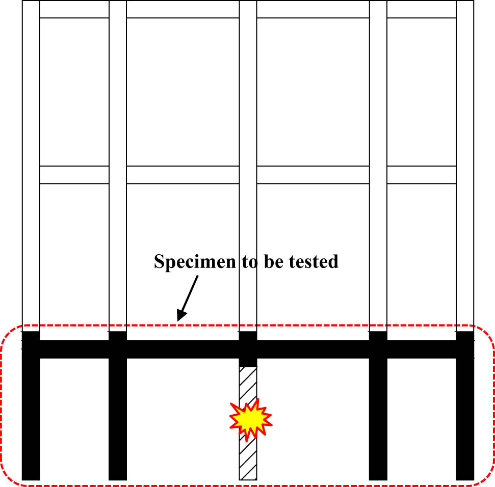
A three-story, four-bay prototype RC frame exhibiting unequal beam spans was designed according to the Chinese concrete design code GB 50010-2010 [20]. The first floor represented a height of 3 m, whereas the higher floors represented a height of 4 m. Based on the similarity theory in which similarity indicates that the ratio of the physical quantities corresponding to the model and prototype remains constant, both the RC frame models were extracted from the prototype frame in Figure 1 and were subsequently scaled down to half. One frame, referred to as S1, was only with steel reinforcement, whereas the other frame, referred to as S2, consisted of steel reinforcement and U-shaped nano CFRP strengthening. The ground center column was removed to simulate the failure of the center ground column due to accidental load; however, the corresponding frame joint was observed to remain intact. The side-span beam was designed herein to simulate the horizontal constraints of the beams from the surrounding bay.
Relationship of the test specimen with a prototype.
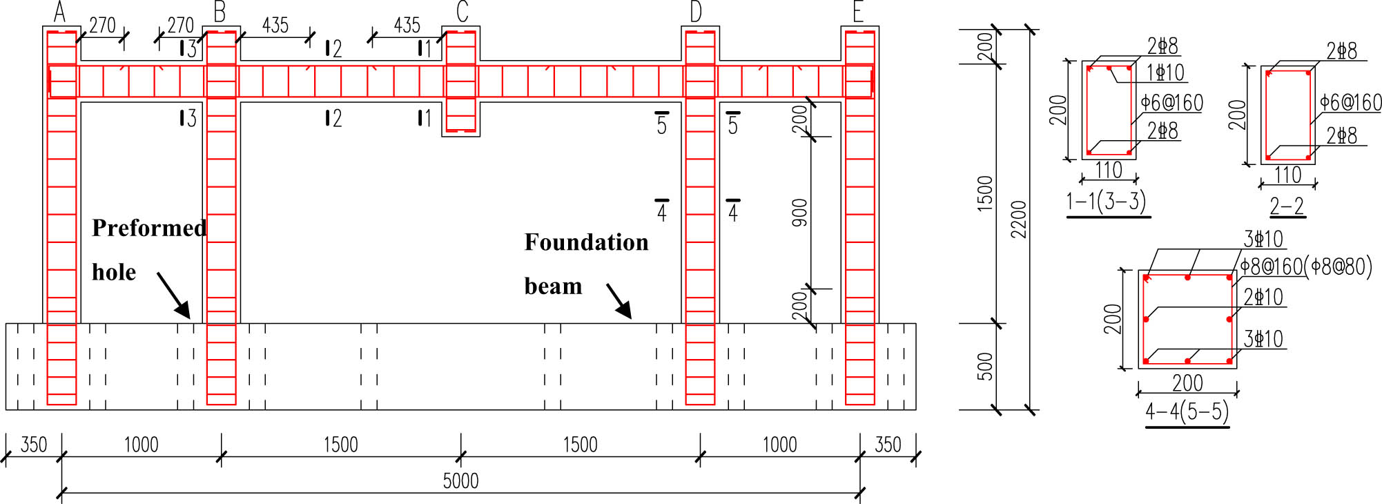
Figure 2 shows the geometric details of the two identical test specimens. The side- and middle-span beams exhibited lengths of 1.0 and 1.5 m, respectively. The side-span beam was set up to simulate the constraint with respect to the lateral movement of the internal columns. A 200 mm-long short column was necessary above the beams to place the loading apparatus above the specimens. Thus, the height of the columns was 1,700 mm. These dimensions were along the centerlines of the respective frame components. This is an important factor because the beam depths and column widths mean that the final clear spans will be slightly less than those shown in Figure 2. All the beams had cross-sections with a width of 110 mm and a height of 200 mm, whereas all the columns had a 200 mm square cross-section. To simulate the boundary conditions, the model frames were developed on a 500 mm-high foundation beam that was fixed using a bolt to the strong reaction floor through a preformed hole, as shown in Figure 2. Ten 100 mm-diameter holes were performed during casting.
Concrete dimensions and steel reinforcements of S1 and S2.
For the beams, the transverse reinforcement spacing for the whole span was 160 mm. All the beams had stirrup diameters of 6 mm. About 135° end hooks were set for the stirrups to satisfy the detailed requirements according to the Chinese concrete design code GB 50010-2010 [20]. A sufficient number of stirrups were used in the columns to prevent shear failure preceding the flexural failure in S1 and S2. The transverse reinforcement of the columns was achieved using 8 mm stirrups with 135° end hooks for a spacing of 160 mm. However, the stirrup spacing was reduced to 80 mm at 0.2 m high regions from the corresponding joint interfaces to avoid potential shear damage of the testing zone and to reinforce the column support and loading regions. Furthermore, the S1 and S2 specimens exhibited a longitudinal reinforcement ratio of 0.46 and 0.81% in the beam bottom and the beam top, respectively, along with a longitudinal reinforcement ratio of 1.57% in each column. These reinforcement percentages were obtained according to the gross areas of the concrete sections. For the beams, two 8 mm-diameter bars and one 10 mm-diameter longitudinal bar were used as the top bars, whereas one 10 mm-diameter bar was cut off at 0.25 times of the beam span from the beam end. The longitudinal steel reinforcement of the columns was determined to avoid flexural yield even though some cracking is expected to have occurred. For all the columns, the diameter of the longitudinal bars was 8 mm. In addition, the HPR300 and HRB400 steel bars were considered to be the stirrups and longitudinal reinforcement, respectively. Note that the HPB300 steel bar type denotes a hot-rolled plain steel bar with a characteristic yield strength of 300 MPa; HRB400 denotes a hot-rolled ribbed steel bar with a characteristic yield strength of 400 MPa. Furthermore, the specified clear cover depth was 10 mm for both models.
2.2 Material properties
Concrete was supplied by a local ready-mix company. Both specimens were produced from the same concrete batch. It was subjected to a 4 week curing period in the test facility with respect to loading failures. Both the specimens had the same concrete grade and rebar specification. Three cubic concrete samples having a dimension of 150 mm × 150 mm × 150 mm and six prism concrete samples having a dimension of 150 mm × 150 mm × 300 mm were considered for the material testing conducted in accordance with the Chinese standard GB/T 50081-2002 [21]. The 28 day compressive strength of the cubic concrete samples was averaged, which yielded 31.9 MPa. On average, the concrete elastic modulus and the Poisson ratio of the prism concrete samples were 34,500 N/mm2 and 0.24, respectively. Three samples with a length of 500 mm for each different specification of steel bars were tested according to the Chinese standard GB/T 228.1-2010 [22]. Table 1 summarizes the displacement control scheme of the MTS actuator in experiment. After divided into three stages, the loading increased stepwise until the complete failure of the frame was achieved. Furthermore, Tables 2 and 3 summarize the mechanical properties of the nano CFRP and epoxy resins, respectively, as indicated by the manufacturer.
Displacement control of the MTS actuator
| First stage | Second stage | Final stage | |
|---|---|---|---|
| Vertical displacement of the failure column (mm) | 0–25 | 25–85 | 85-failure |
| Loading rate (mm/min) | 1 | 4 | 10 |
| Each step (mm) | 5 | 10 | 15 |
Properties of nano CFRP
| Material | Weight (g/mm2) | Thickness (mm) | Tensile strength (MPa) | Elasticity modulus (GPa) | Failure strain (%) |
|---|---|---|---|---|---|
| Nano CFRP | 300 | 0.167 | 4,340 | 240 | 1.7 |
Properties of epoxy
| Material | Compressive strength (MPa) | Flexural strength (MPa) | Tensile strength (MPa) | Elasticity modulus (MPa) | Failure strain (%) | Bond strength (MPa) |
|---|---|---|---|---|---|---|
| Epoxy | 81 | 97 | 68 | 2,870 | 2.9 | 4 |
2.3 Strengthening schemes
S2 was strengthened using the layered U-shaped nano CFRP sheets. Considering the length of the potential plastic hinge, the strengthening length of the beam end was 350 mm; considering that the stirrups have certain spacing, the strengthening scheme with intermittent spacing is adopted; therefore, this area was strengthened using two identical 150 mm-wide U-shaped nano CFRP sheets having a center-to-center spacing of 200 mm. Considering that the stirrups have certain spacing and to simulate this characteristic as far as possible, a nonstrengthened area of 50 mm clear spacing was reserved. Figure 3 illustrates the S2 model. The nano CFRP strengthening process can be given as follows.
The area of the specimen in which the continuous nano CFRP sheet was to be glued was sandblasted to eliminate any surface cement paste and round off the beam edges. Here, the bond area was ground to eliminate any possible irregularities and achieve a desirable smooth bond surface; furthermore, the residues were eliminated using compressed air.
The concrete surface was saturated with epoxy, a two-component adhesive of a resin, and a hardener primarily engineered for structural applications and directly supplied by the manufacturer.
Once the resin became tacky, the nano CFRP sheet was epoxy-bonded to the beam surface. Each wrap was continuous at the bottom face of the beam and terminated close to the top of the beam on both faces.
Finally, the nano CFRP sheets were saturated with epoxy.
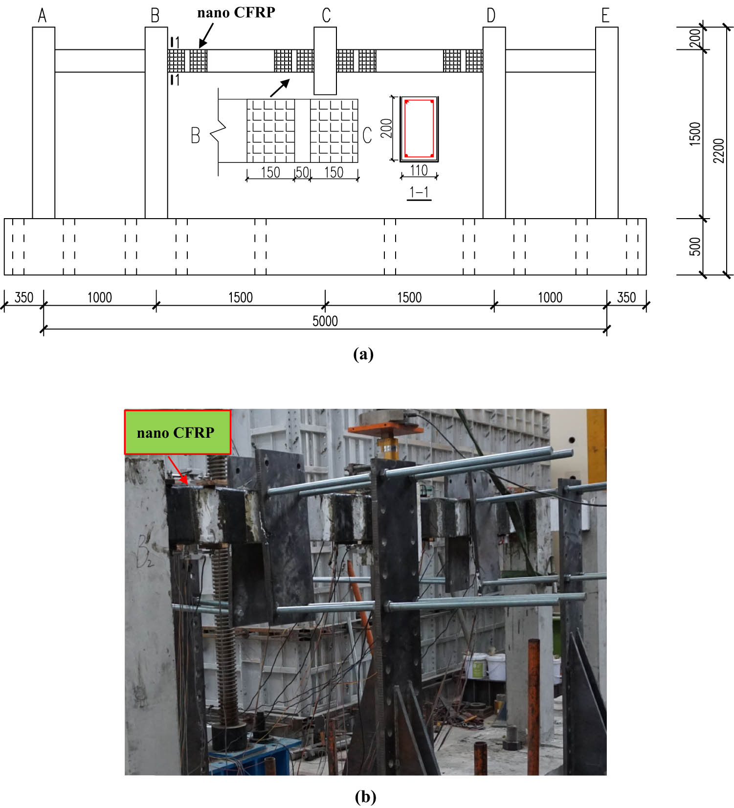
The S2 model with nano CFRP: (a) schematic diagram and (b) photograph.
2.4 Test setup and instrumentation
For the tests, a disproportionate collapse situation was simulated by eliminating the center support column of each frame. Figure 4 shows a schematic representation and a general view of the test setup. The material testing system (MTS) actuator placed at the top of the failure column was used to load the frames via displacement control. The mechanical properties of steel bars are given in Table 4. Meanwhile, a load cell with a 1,000 kN measuring range and installed under the actuator was used to measure the applied vertical load. In addition, Figure 4 displays two collars that were designed to prevent unwanted failures resulting from any out-of-plane deformation of the testing frame. In particular, the collars were manufactured using two steel plates tightly bolted together in opposite directions out of the beam plane and were subsequently bolted to the lateral steel braces. About 5 mm gaps were intentionally left between the collars and the beam surfaces in the initial loading stage to avoid unwanted frictional forces from acting on the columns in the early stages of the tests.
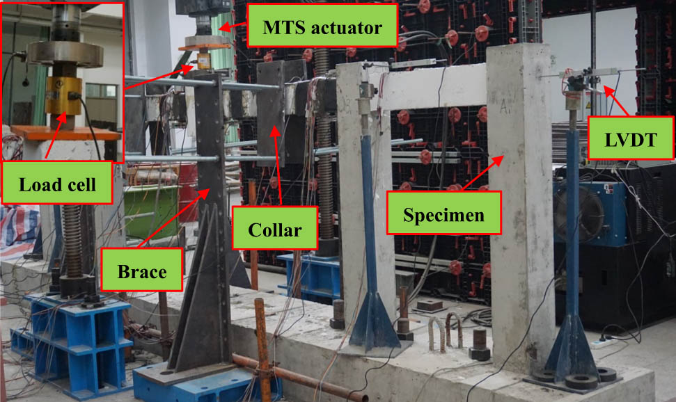
Typical test setup.
Properties of the steel bars (average values)
| Material | Diameter(mm) | Bar type | Elastic modulus (GPa) | Yield strength (MPa) | Ultimate tensile strength (MPa) | Fracture strain (%) |
|---|---|---|---|---|---|---|
| Longitudinal reinforcement | 8 | Ribbed | 201 | 462 | 557 | 12 |
| 10 | Ribbed | 207 | 452 | 534 | 14 | |
| Stirrup | 6 | Plain | 216 | 345 | 433 | 19 |
| 8 | Plain | 212 | 357 | 429 | 18 |
Four horizontal linear variable differential transformers (LVDTs) were placed at each joint of the specimens to measure the horizontal movements of the columns for determining the axial stiffness values of the horizontal restraints for the test specimen. Figure 5 shows the LVDT layout. Accordingly, the deformation information of the longitudinal reinforcements is the key to analyze the collapse mechanism of the frame; thus, strain gauges, whose layout is presented in Figure 5, were used to measure the strains of the beam rebars. The reinforcement strains at the potential plastic hinge region were measured. Furthermore, all sensors including strain gauges, load cells, and LVDTs were connected with a strain collection system that was activated for data storage and operated at a frequency of 5 s each time. The beam surface was brushed with lime and divided using a dense mesh to monitor the crack development at all the locations throughout the testing period. After each loading increment, a few seconds were allotted for the instrumentation to record stable data and to observe new cracks on the specimens.
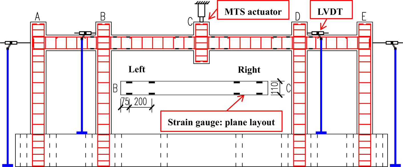
Layout of LVDTs and steel strain gauges.
3 Experimental results and discussion
3.1 Crack patterns and failure mode
Figure 6 denotes the failure mode of S1. The crack patterns of the beams at both sides of the middle joint were symmetrical, except at the local regions near the joint. Because of the lack of rotational restraint in the middle joint, the middle joint can be rotated to one side with a wide crack, resulting in a fracture at the bottom bars at or near the joint interface on that side. The cracks were considered severe and extensive at three regions, i.e., near the joint interface, at the beam ends, and between the curtailment points of the top bars. At the beam end, the crack that appeared at the top of the beam and developed toward the belly along the beam height direction conformed to the mode of flexural crack. As the loading increased and cracks began to develop, plastic hinges would develop at the curtailment point of the top reinforcement in the beam because of the discontinuity in longitudinal reinforcement, as depicted in Figure 6(a). Consequently, the hinge significantly enhanced the deformation capacity of S1. In the compressive arch action stage, the reinforcement in the beam bottom of the middle joint fractured, as shown in Figure 6(b). Final failure was induced by the fracture of the beam top reinforcement in the plastic hinge region, as clearly illustrated in Figure 6(c). Concrete crushing was observed; however, it was not obvious at the bottom of the beam end.
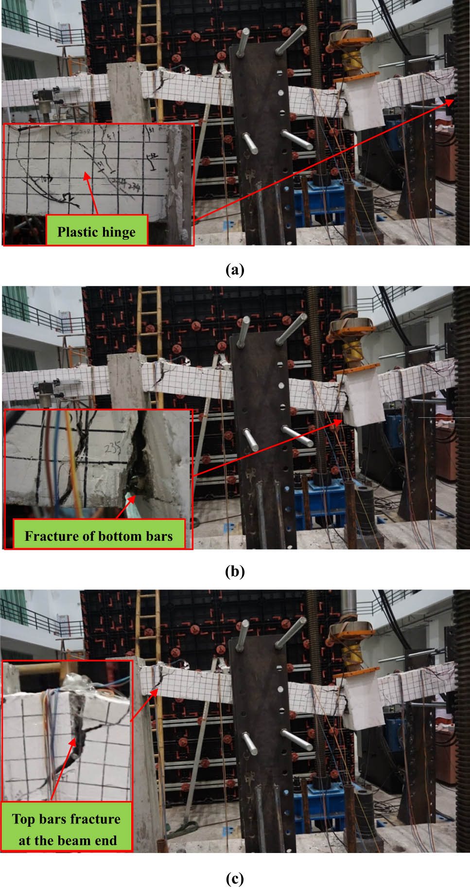
Crack pattern and failure mode of S1: (a) at the beam end near column D; (b) at the middle point; and (c) the failure mode of S1.
Figure 7 denotes the failure mode of S2. As the loading increased, the plastic hinge began to develop at the curtailment point of the beam top reinforcement, mainly because of discontinuity with respect to the longitudinal reinforcement. In the compressive arch action stage, the reinforcement in the beam bottom of the middle joint fractured, as shown in Figure 7(a). In contrast to the scene in S1, the top bar of the beam end of S2 yielded and fractured at the compressive arch action stage after the beam bottom reinforcement of the middle joint was fractured, as illustrated in Figure 7(b).
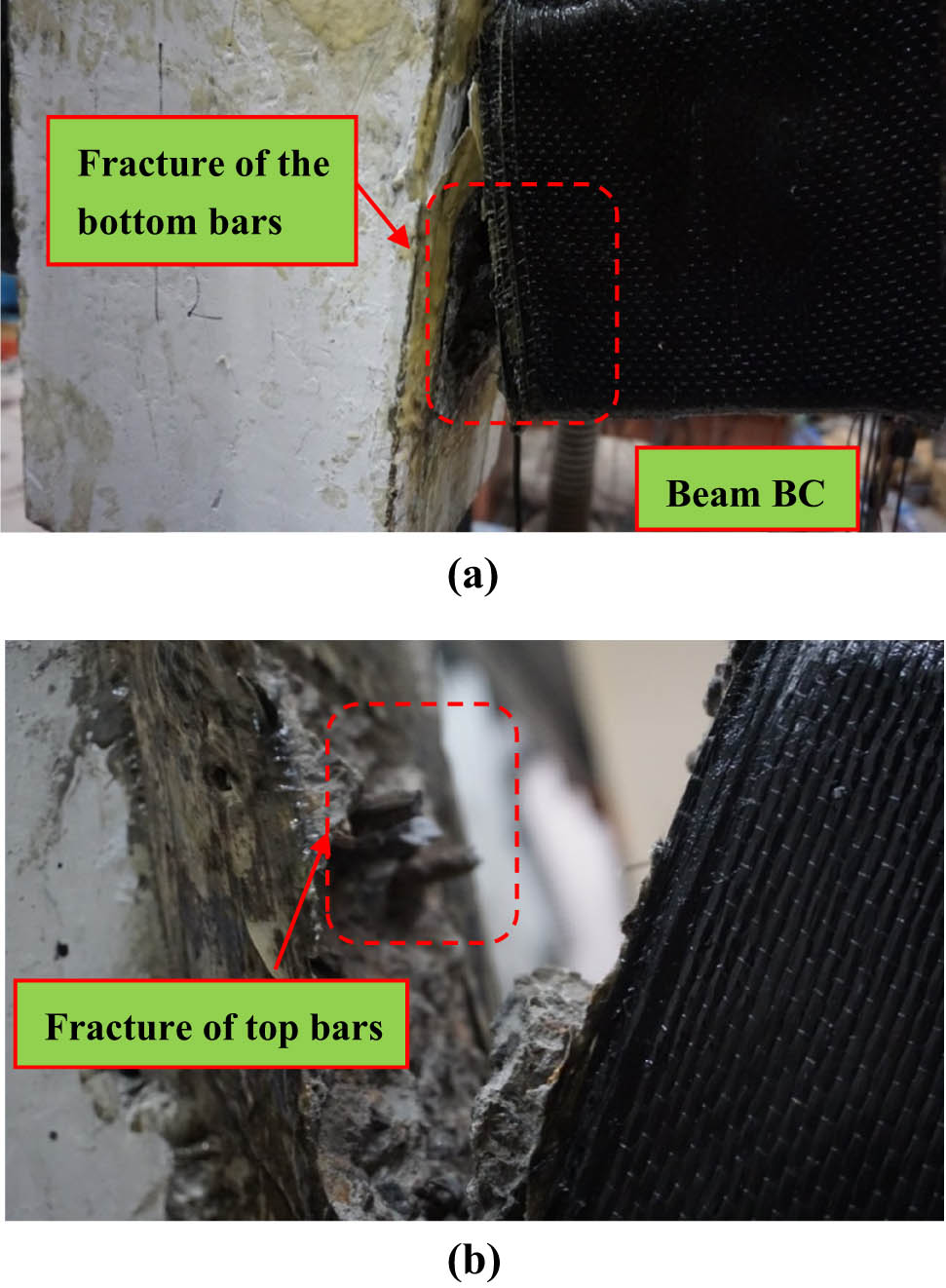
Crack pattern and failure mode of S2: (a) at the middle joint and (b) at the beam end near column A.
3.2 Load–displacement histories
The tests were terminated once the fracture of the top reinforcement was achieved at one of the beam ends. Prior to failure, the specimens experienced large deformations and rotations. The beam surfaces were not observed to contact the collars of braces. Consequently, at the end of the tests, the middle joint displacements became 350.1 mm (23.3% of the single-span length) for S1 and 206.5 mm (13.8% of the single-span length) for S2. Herein, the experimental results and observations of the two specimens were demonstrated based on the load–displacement histories, horizontal displacement variation, strain variation, crack patterns and failure mode, rotational capacity, and energy dissipation capacity. Furthermore, for model S1, the progressive collapse process was classified under three primary stages, i.e., flexural action, compressive arch action, and catenary action; for S2, the process could only be classified into two primary stages, i.e., flexural action and compressive arch action.
Figure 8 denotes section OA, which refers to the stage characterized via flexural action. Flexural action would develop until all the plastic hinges are present at the middle joint interfaces and the beam ends [23]. Section AB could be considered to be the compressive stage, where the compressive arch action contributes to the resistance. Section BC is the catenary stage, which denotes the transformation of the strain in the bars in the original compressive region of the beams from compression to tension. It is also noteworthy that around the starting point of the catenary stage (point B), the surrounding columns would change their movements from outward to inward and then back to their initial positions (with a horizontal displacement of 0 mm). This stage begins when the vertical displacement of the failure column is 222.3 mm for S1. However, the material test for S2 ends in the stage of compressive arch action. The bond failure of the nano CFRP sheets did not occur during testing via visual observations.
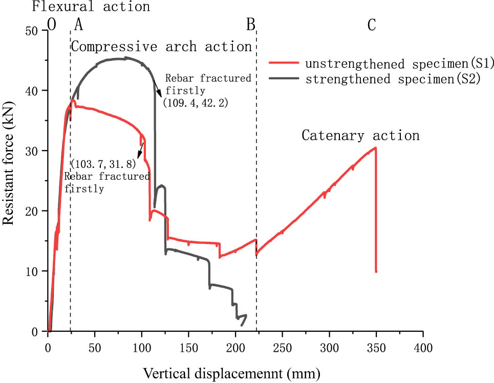
Resistance force versus the vertical displacement of the middle column of the frames.
The overall structural behavior of each RC frame was characterized based on the resistance force versus vertical displacement history of the middle joint. Beam deflection was represented by the vertical displacement of the middle joint, which was obtained from the actuator in-built displacement transducer. Figure 8 shows the resistance force versus vertical displacement histories of S1 and S2.
In the case of S1, the middle joint region and beam ends were initially subjected to positive and negative bending moments, respectively. Hence, bottom reinforcement rapidly achieved yield at the middle joint. Afterward, the top reinforcement yields at both the beam end indicated that the plastic hinges have formed and that the flexural action has attained its capacity. In the case of a small middle joint vertical displacement, the beam ends attempted to push the two columns outward as the beam deflected downward. Regardless, such action was prevented by the horizontal restraints at the column side, which generated the axial compressive force in the beam. Due to the compressive force in the beam, load resistance was enhanced to become greater than the flexural capacity.
When the vertical displacement was 26.7 mm, the resistance force achieved its maximum value of 38.4 kN in the compressive stage and subsequently decreased to 12.7 kN until the end of the compressive stage (with a vertical displacement of 222.3 mm). Here, the sudden reduction in the applied load at the middle joint was caused by the fracture of the bottom rebars at the middle joint interfaces, and the corresponding displacement was 103.7 mm. Specifically, the crushing of concrete and fracture of rebars allowed the beam ends to rotate and pull in the columns. As the vertical displacement for the middle joint widened, the beam axial force gradually switched from compression to tension. Consequently, a catenary action could be observed when the beam was in pure tension at a middle joint vertical displacement of 222.3 mm. Due to the development of catenary action in the damaged structure, the resistance force further increased in the catenary stage until the end of the test. The catenary action completely utilized the reserve strength of steel reinforcement. Furthermore, the ultimate capacity of catenary action was determined solely based on the top reinforcement because of the fracture of the bottom reinforcement near the joint interfaces during the development of catenary action. The test ended when the center column attained a vertical displacement of 350.1 mm as fracture developed at the top rebar at the beam end. The catenary action recorded a maximum resistance force of 30.5 kN, which was 0.79 times that of the compressive arch action.
In the case of S2, the vertical displacement of 24.0 mm was assigned to the end of the flexural action stage because of which the vertical displacement corresponded to the formation of plastic hinges in the beams. Furthermore, when the vertical displacement was 82.7 mm, the resistance force achieved its maximum value of 45.5 kN and then gradually decreased to 42.9 kN until a vertical displacement of 109.4 mm was reached. Beyond this point, the resistance force decreased several times due to the rebar fractures. The test ended in the stage of compressive arch action for a vertical displacement of 206.5 mm.
After the comparison between S1 and S2, the scheme of strengthening at the beam end using the U-shaped nano CFRP may result in higher rotational stiffness, limited deformation, and present a smaller rotation at failure. It is not conducive to the development of a catenary resistance mechanism. However, this strengthening scheme improves the compression failure ability at the beam end, resulting in an increase of the maximum resistance force at the compressive stage by 18%.
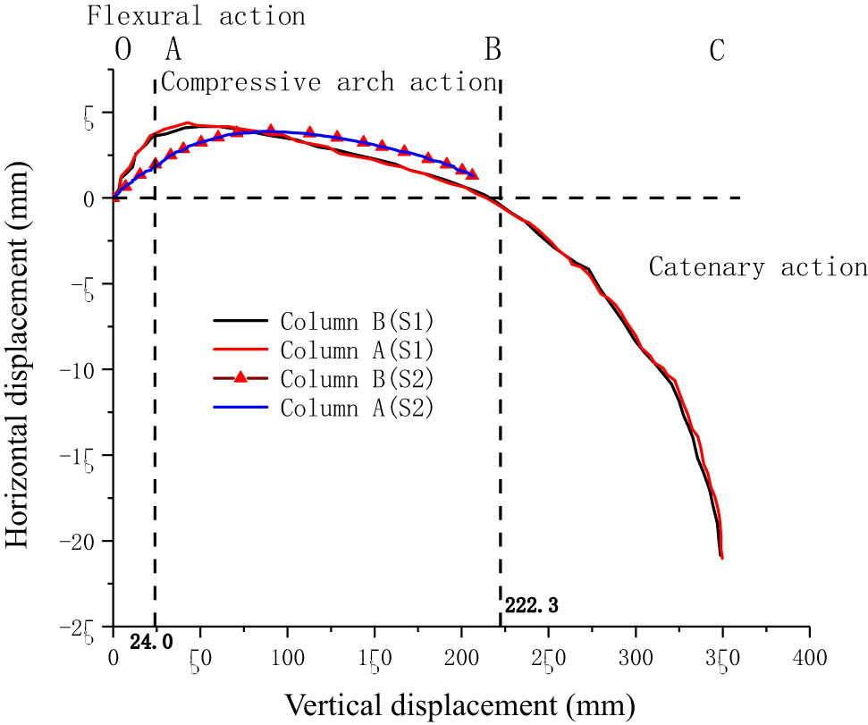
Horizontal displacements of the joints versus the vertical displacement of the middle column for S1 and S2.
3.3 Horizontal displacement variation
Figure 9 denotes the horizontal displacements of the joints at the adjacent and external columns (Figure 5, locations of LVDTs) versus the vertical displacements of the center column of S1 and S2. In the case of S1, the adjacent and external joints initially moved outward (i.e., horizontally away from the center column) and achieved maximum values of approximately 4.4 mm at a vertical displacement of 42.7 mm when the vertical displacement increased in the flexural action and compressive stages. Subsequently, these joints moved to their initial positions (with a horizontal displacement of 0 mm) at a vertical displacement of approximately 222.3 mm. Further, the joints continued to move inward until the end of the test in the catenary stage, with a horizontal displacement of approximately 20.8 mm inward.
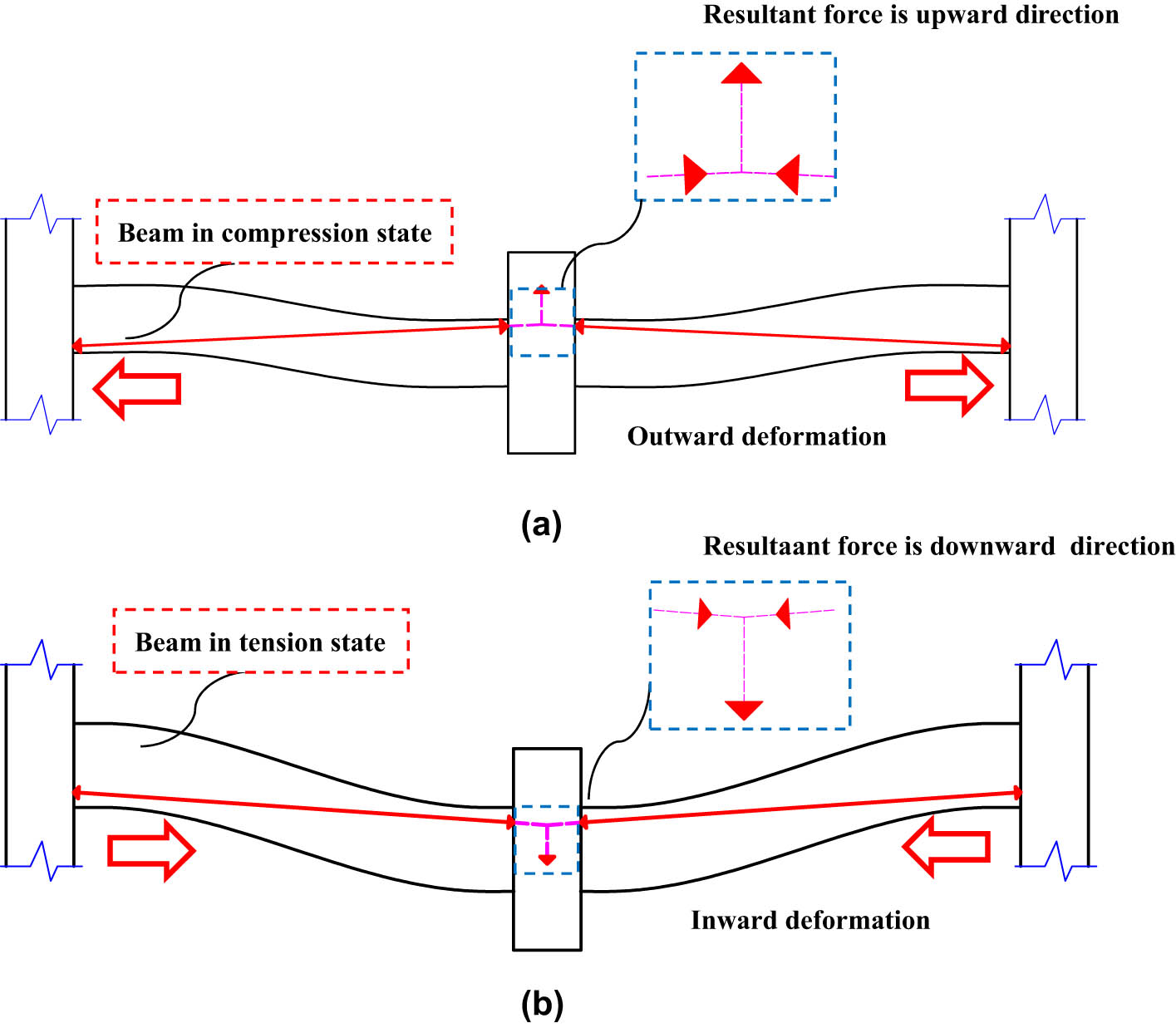
Schematic of the beneficial and adverse compressive arch actions to the resistance force: (a) beneficial action before vertical displacements of 26.7 and 82.7 mm for S1 and S2, respectively and (b) adverse action owing to the vertical displacements of 222.3 and 206.5 mm for S1 and S2, respectively.
The response for S1 was similar to that for S2. With an increase in the vertical displacement, the adjacent and external joints initially moved outward and achieved their maximum value of approximately 3.9 mm at a vertical displacement of 95.9 mm. Next, the joints exhibited a tendency to move to their initial positions. At a vertical displacement of approximately 215.5 mm, the test ended in the compressive stage with a horizontal displacement of approximately 1.3 mm outward.
Concerning the mechanism, the compressive arch action was activated and contributed to the resistance force in the compressive stage. Obviously, the length of the line connecting the two diagonal corners of the beam exceeded the horizontal length of the beam in the centroidal axis. When the center column was pushed downward, the originally inclined diagonal line (pressure line) moved gradually into a horizontal position, as shown in Figure 10(a). Consequently, the adjacent and external joints would be pushed outward, triggering the compressive arch action. This explains the gradual increase in the resistance force as the vertical displacements increased during the flexural action stage. Furthermore, the beams remain in compression, with the vertical displacements of 26.7 and 82.7 mm for S1 and S2, respectively.
The directions of the vertical components of the compressive forces in the beams began to shift from pointing upward to downward, imposing an additional load on the center column, which implied a transition from the beneficial compressive arch action to the adverse catenary action, as illustrated in Figure 10(b). These observations explain the gradual decrease in resistance force as the vertical displacements increased to 222.3 and 206.5 mm for S1 and S2, respectively. In this stage, the frame experiences a large deformation majorly, and the joints would be tensioned inward.
3.4 Strain variation
To assess the effects of the retrofitting strategy on rebars, local strains were monitored using foil-type strain gauges fixed on the rebars. Figure 11 shows the strains of the rebars in beam BC (Figure 5) varying with the vertical displacement of eliminating the middle column. It should be noted that the strain values given are the mean value of all results in the specific zone. In flexural action, the strains of S1 and S2 showed a similar trend. In detail, the strains of rebars at the top left end of the beam were positive, and increased almost linearly to the yield strain (up to 2,300 µε) with vertical displacement increasing. Conversely, the strains of rebars at the top right end of the beam were negative and reduced gradually to about 2,000 µε with the increase of vertical displacement. These phenomena indicated the elastic behavior of rebars during the flexural action.
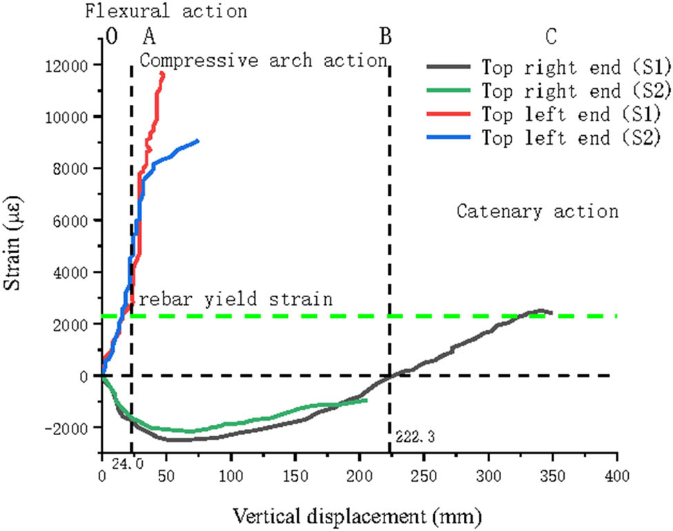
Strains of the rebars in beam BC for S1 and S2.
In compressive arch action, the strains at the top left end of rebars continued to increase and developed in the hardening stage. The strain of S2 can reach its peak (up to 8,500 µε) with the vertical displacement increasing to 75.2 mm. However, the largest strain of S1 was almost 12,000 µε when the vertical displacement increased to 49.5 mm. These results reflected that the nano CFRP can anticipate efficiently in the loading process with stress redistribution, and consequently, reduce the stress of rebars and enlarge the deformability. Similar phenomena can be observed at the top right end of rebars. The strains of S2 were obviously less than S1 due to the anticipation of nano CFRP.
In catenary action, the strain at the top right end of rebars in the S1 case changed from a negative value to a positive value, indicating the tension action in the top region. Due to the fracture of rebars and nano CFRP in the section location, S2 lost the resistance capability in the final compressive arch action and failed to experience catenary action without strains results. This is consistent with the relationship between the resistance force and vertical displacement shown in Figure 8, which proves the lack of anti-progressive collapse capacity of RC frames after the retrofit.
3.5 Rotational and energy dissipation capacity
The rotational capacities of the beams were evaluated via chord rotations. The chord rotation of the beams was calculated as the ratio of the middle joint vertical displacement with respect to the length of the single-span beam (1,500 mm) as defined in UFC 4-023-03 (2013) [24]. Thus, the chord rotations of S1 and S2 at the final middle joint displacement were 0.23 and 0.14 rad, respectively. This indicates that the rotational capacity of the frame strengthened using nano CFRP at the beam end was lower than that of a bare frame. This can be due to the fact that the plastic hinges in joint regions in S2 develop insufficiently due to the limitation of nano CFRP. In that case, the crack appears majorly in the section, rather than the joint region.
Accordingly, the energy dissipation capacities of S1 and S2 were represented by the area enclosed by the resistance force–vertical displacement curve and x-axis, respectively, as depicted in the schematic shown in Figure 12. Here, the areas of S1 and S2 were 7985.1 and 5505.2 N m, respectively. Subsequently, the energy dissipation capacity of S2 could be easily obtained as 0.69 times that of S1, indicating that S2 failed to improve the dissipation capacity of progressive collapse even though it was strengthened using the U-shaped nano CFRP, resulting in lower ductility than that obtained in case of S1. Therefore, the frame strengthened at the beam end using the U-shaped nano CFRP limits the rotational capacity, which implies that in the stage of flexural action and compressive arch action, S2 requires greater loading compared to S1 if the same vertical displacement must be achieved. Sequentially, it causes energy dissipation capacity to focus on the stage before the catenary and also adversely affects the development of the catenary.
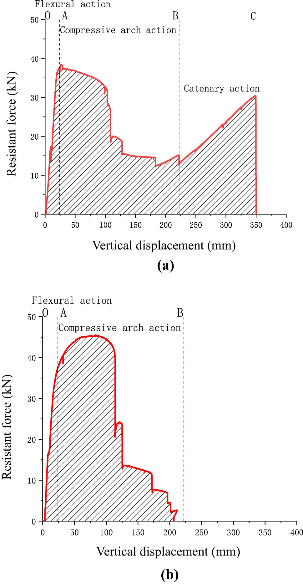
Schematic of the energy dissipation capacity of the specimen: (a) S1 and (b) S2.
3.6 Discussion
Prior to the final failure, three loading stages (flexural action, compressive arch action, and catenary action) were identified to describe the progressive collapse process of S1, whereas only two loading stages (flexural action and compressive arch action) were identified for S2. Figure 8 describes that S1 and S2 exhibited almost similar resistance performances during the flexural action stage. In the subsequent compressive arch stage, the maximum resistance forces of S2 can be improved by 18.5% after nano CFRP retrofitting, increasing from 38.4 kN (S1 case) to 45.5 kN (S2 case). Correspondingly, the vertical displacement of eliminating the middle column increased by 3.09 times, increasing from 26.7 to 82.7 mm, indicating the significant improvement of deformation capability, as listed in Table 5. For the last catenary stage, S1 developed the plastic hinge continuously with more extension of rebars and deformability as shown in Figure 6. Unfortunately, S2 failed to experience this stage due to the fact that the nano CFRP can hinder the crack spreading of concrete and hardening of rebars, and consequently, the fractures of rebars and nano CFRP occurred in the normal section without plastic hinge developing sufficiently, as shown in Figure 7.
Comparison of the test results
| Specimen ID | Maximum resistance force at the compressive stage (kN) | Vertical displacement at the first bar fracture (mm) | Initial vertical displacement at the catenary stage (mm) | Maximum vertical displacement (mm) |
|---|---|---|---|---|
| S1 | 38.4 | 103.7 | 222.3 | 350.1 |
| S2 | 45.5 | 109.4 | — | 206.5 |
| Δ (%) | 18.5 | 5.5 | — | −41.0 |
Note: Δ = (S2 − S1)/S1 × 100%.
It can be concluded that the retrofitting strategy using U-shaped nano CFRP strengthening the beam ends can improve its mechanical properties in terms of strength and ductility, and postpone shear failure of the joint core region. Due to the high performance and ease of installation, the nano CFRP material has much potential in retrofitting structures, particularly beam component and beam-column subassemblies. However, this strategy has its own deflects in anti-progressive collapse, which should be considered in retrofitting design and implementation.
4 Conclusion
This article investigated the effect of nano CFRP on improving the strength and ductility of RC frames by means of retrofitting the beam component. Two four-bay RC frame specimens, among which one was strengthened using U-shaped nano CFRP at the beam end and the other was not strengthened, were tested to understand the mechanical behavior of progressive collapse. The retrofitting effects were studied and identified through crack patterns, failure mode, load–displacement curves, horizontal displacement, strains, and rotational and energy dissipation capacity. The major conclusions were the following:
The frame S2 strengthened using U-shaped nano CFRP at the beam end experienced the same ductile beam-hinge failure mode as S1. However, the mechanical characteristics of S2 have been improved significantly, namely 18.5% in load-bearing capacity and 3.09 times in ductility compared to S1, which demonstrated the excellent retrofitting effects of nano CFRP.
S2 exhibited a much smaller response in strains of rebars and maximum horizontal displacements for beam-column subassemblies than S1, which reflected the efficient anticipation of nano CFRP in load bearing and deformability.
During the progressive collapse process, S2 only experienced the flexural action and compressive arch action and failed to enter the catenary action. Therefore, this strategy retrofitting beam end has its own defects in anti-progressive collapse, which should be considered in retrofitting design.
Acknowledgements
The authors wish to express their gratitude and sincere appreciation to the National Natural Science Foundation of China (Grant No. 51408131 and No. 51508099) for financing this research.
-
Funding information: National Natural Science Foundation of China (Grant No. 51408131 and No. 51508099).
-
Author contributions: All authors have accepted responsibility for the entire content of this manuscript and approved its submission.
-
Conflict of interest: The authors state no conflict of interest.
-
Data availability statement: The datasets generated during and/or analyzed during the current study are available from the corresponding author on reasonable request.
References
[1] Jian H, Li S, Liu HH. Testing and analysis on progressive collapse-resistance behavior of RC frame substructures under a side column removal scenario. J Perform Constr Fac. 2016;30(5):04016022.10.1061/(ASCE)CF.1943-5509.0000873Suche in Google Scholar
[2] Su Y, Tian Y, Song X. Progressive collapse resistance of axially-restrained frame beams. ACI Struct J. 2009;106(5):600–7.10.14359/51663100Suche in Google Scholar
[3] Melo J, Varum H, Rossetto T. Cyclic behavior of interior beam-column joints reinforced with plain bars. Earthquake Eng Struct Dyn. 2015;44(9):1351–71.10.1002/eqe.2521Suche in Google Scholar
[4] Duan H, Hueste MBD. Seismic performance of a reinforced concrete frame building in China. Eng Struct. 2012;41:77–89.10.1016/j.engstruct.2012.03.030Suche in Google Scholar
[5] Rodrigues H, Varum H, Arede A, Costa A. Behavior of reinforced concrete column under biaxial cyclic loading-state of the art. Int J Adv Struct Eng. 2013;5(1):1–12.10.1186/2008-6695-5-4Suche in Google Scholar
[6] Kamble M, Lakhnot AS, Bartolucci SF, Littlefield AG, Picu CR, Koratkar N. Improvement in fatigue life of carbon fiber reinforced polymer composites via a nano-silica modified matrix. Carbon. 2020;170:220–4.10.1016/j.carbon.2020.08.029Suche in Google Scholar
[7] Guo Z, Zhu QX, Wu WD, Chen Y. Research on bond-slip performance between pultruded glass fiber-reinforced polymer tube and nano-CaCO3 concrete. Nanotechnol Rev. 2020;9:637–49.10.1515/ntrev-2020-0036Suche in Google Scholar
[8] Zhang Z, Hsu CT. Shear strengthening of reinforced concrete beams using carbon-fiber-reinforced polymer laminates. J Compos Constr. 2005;2:158–69.10.1061/(ASCE)1090-0268(2005)9:2(158)Suche in Google Scholar
[9] Wang WW, Li G. Experimental study and analysis of RC beams strengthened with CFRP laminates under sustaining load. Int J Solids Struct. 2006;43(6):1372–87.10.1016/j.ijsolstr.2005.03.076Suche in Google Scholar
[10] Garcia R, Hajirasouliha I, Pilakoutas K. Seismic behavior of deficient RC frames strengthened with CFRP composites. Eng Struct. 2010;32(10):3075–85.10.1016/j.engstruct.2010.05.026Suche in Google Scholar
[11] Mofidi A, Chaallal O. Effect of steel stirrups on shear resistance gain due to externally bonded fiber-reinforced polymer strips and sheets. ACI Struct J. 2014;111:353–61.10.14359/51686527Suche in Google Scholar
[12] Esmaeeli E, Barros JAO, Sena-Cruz J, Fasan L, Liprizzi FR, Melo J, et al. Retrofitting of interior RC beam-column joints using CFRP strengthened SHCC: cast-in-place solution. Compos Struct. 2015;122:456–67.10.1016/j.compstruct.2014.12.012Suche in Google Scholar
[13] Ma CL, Wang DY, Wang ZY. Seismic retrofitting of full-scale RC interior beam-column-slab subassemblies with CFRP wraps. Compos Struct. 2017;159:397–409.10.1016/j.compstruct.2016.09.094Suche in Google Scholar
[14] Adebayo O, Kim ML. Flexural behavior and efficiency of CFRP-laminate reinforced recycled concrete beams: Optimization using linear weighted sum method. Compos Struct. 2021;260:113259.10.1016/j.compstruct.2020.113259Suche in Google Scholar
[15] Zakaria MR, Akil HM, Omar MF, Abdullah MMAB, Rahman AAA, Othman MBH. Improving flexural and dielectric properties of carbon fiber epoxy composite laminates reinforced with carbon nanotubes interlayer using electrospray deposition. Nanotechnol rev. 2020;2:1170–82.10.1515/ntrev-2020-0090Suche in Google Scholar
[16] Dassan EGB, Rahman AAA, Abidin MSZ, Akil HM. Carbon nanotube-reinforced polymer composite for electromagnetic interference application: a review. Nanotechnol rev. 2020;9:768–88.10.1515/ntrev-2020-0064Suche in Google Scholar
[17] Truong GT, Tran HV, Choi KK. Tensile behavior of carbon fiber-reinforced polymer composites incorporating nanomaterials after exposure to elevated temperature. J Nanomater. 2019;4139208:1–14.10.1155/2019/4139208Suche in Google Scholar
[18] Irshidat MR, Al-Saleh MH, Almashagbeh H. Effect of carbon nanotubes on strengthening of RC beams retrofitted with carbon fiber/epoxy composites. Mater Design. 2016;89:225–34.10.1016/j.matdes.2015.09.166Suche in Google Scholar
[19] Irshidat MR, Al-Saleh MH. Flexural strength recovery of heat-damaged RC beams using carbon nanotubes modified CFRP. Constr Build Mater. 2017;145:474–82.10.1016/j.conbuildmat.2017.04.047Suche in Google Scholar
[20] GB50010-2010. Code for design of concrete structures, China Architecture and Building Press, Beijing China, 2010. (In Chinese).Suche in Google Scholar
[21] GB/T 50081-2002. Standard for test method of concrete physical and mechanical properties, China Architecture and Building Press, Beijing China, 2002. (In Chinese).Suche in Google Scholar
[22] GB/T 228.1-2010. Metallic materials – Tensile testing at ambient temperature, China Architecture and Building Press, Beijing China, 2010. (In Chinese).Suche in Google Scholar
[23] Yu J, Tan K. Experimental and numerical investigation on progressive collapse resistance of reinforced concrete beam-column sub-assemblages. Eng Struct. 2013;55:90–106.10.1016/j.engstruct.2011.08.040Suche in Google Scholar
[24] UFC 4-023-03. Design of buildings to resist progressive collapse, Department of Defense, USA, 2013.Suche in Google Scholar
© 2022 Weihong Chen et al., published by De Gruyter
This work is licensed under the Creative Commons Attribution 4.0 International License.
Artikel in diesem Heft
- Research Articles
- Theoretical and experimental investigation of MWCNT dispersion effect on the elastic modulus of flexible PDMS/MWCNT nanocomposites
- Mechanical, morphological, and fracture-deformation behavior of MWCNTs-reinforced (Al–Cu–Mg–T351) alloy cast nanocomposites fabricated by optimized mechanical milling and powder metallurgy techniques
- Flammability and physical stability of sugar palm crystalline nanocellulose reinforced thermoplastic sugar palm starch/poly(lactic acid) blend bionanocomposites
- Glutathione-loaded non-ionic surfactant niosomes: A new approach to improve oral bioavailability and hepatoprotective efficacy of glutathione
- Relationship between mechano-bactericidal activity and nanoblades density on chemically strengthened glass
- In situ regulation of microstructure and microwave-absorbing properties of FeSiAl through HNO3 oxidation
- Research on a mechanical model of magnetorheological fluid different diameter particles
- Nanomechanical and dynamic mechanical properties of rubber–wood–plastic composites
- Investigative properties of CeO2 doped with niobium: A combined characterization and DFT studies
- Miniaturized peptidomimetics and nano-vesiculation in endothelin types through probable nano-disk formation and structure property relationships of endothelins’ fragments
- N/S co-doped CoSe/C nanocubes as anode materials for Li-ion batteries
- Synergistic effects of halloysite nanotubes with metal and phosphorus additives on the optimal design of eco-friendly sandwich panels with maximum flame resistance and minimum weight
- Octreotide-conjugated silver nanoparticles for active targeting of somatostatin receptors and their application in a nebulized rat model
- Controllable morphology of Bi2S3 nanostructures formed via hydrothermal vulcanization of Bi2O3 thin-film layer and their photoelectrocatalytic performances
- Development of (−)-epigallocatechin-3-gallate-loaded folate receptor-targeted nanoparticles for prostate cancer treatment
- Enhancement of the mechanical properties of HDPE mineral nanocomposites by filler particles modulation of the matrix plastic/elastic behavior
- Effect of plasticizers on the properties of sugar palm nanocellulose/cinnamon essential oil reinforced starch bionanocomposite films
- Optimization of nano coating to reduce the thermal deformation of ball screws
- Preparation of efficient piezoelectric PVDF–HFP/Ni composite films by high electric field poling
- MHD dissipative Casson nanofluid liquid film flow due to an unsteady stretching sheet with radiation influence and slip velocity phenomenon
- Effects of nano-SiO2 modification on rubberised mortar and concrete with recycled coarse aggregates
- Mechanical and microscopic properties of fiber-reinforced coal gangue-based geopolymer concrete
- Effect of morphology and size on the thermodynamic stability of cerium oxide nanoparticles: Experiment and molecular dynamics calculation
- Mechanical performance of a CFRP composite reinforced via gelatin-CNTs: A study on fiber interfacial enhancement and matrix enhancement
- A practical review over surface modification, nanopatterns, emerging materials, drug delivery systems, and their biophysiochemical properties for dental implants: Recent progresses and advances
- HTR: An ultra-high speed algorithm for cage recognition of clathrate hydrates
- Effects of microalloying elements added by in situ synthesis on the microstructure of WCu composites
- A highly sensitive nanobiosensor based on aptamer-conjugated graphene-decorated rhodium nanoparticles for detection of HER2-positive circulating tumor cells
- Progressive collapse performance of shear strengthened RC frames by nano CFRP
- Core–shell heterostructured composites of carbon nanotubes and imine-linked hyperbranched polymers as metal-free Li-ion anodes
- A Galerkin strategy for tri-hybridized mixture in ethylene glycol comprising variable diffusion and thermal conductivity using non-Fourier’s theory
- Simple models for tensile modulus of shape memory polymer nanocomposites at ambient temperature
- Preparation and morphological studies of tin sulfide nanoparticles and use as efficient photocatalysts for the degradation of rhodamine B and phenol
- Polyethyleneimine-impregnated activated carbon nanofiber composited graphene-derived rice husk char for efficient post-combustion CO2 capture
- Electrospun nanofibers of Co3O4 nanocrystals encapsulated in cyclized-polyacrylonitrile for lithium storage
- Pitting corrosion induced on high-strength high carbon steel wire in high alkaline deaerated chloride electrolyte
- Formulation of polymeric nanoparticles loaded sorafenib; evaluation of cytotoxicity, molecular evaluation, and gene expression studies in lung and breast cancer cell lines
- Engineered nanocomposites in asphalt binders
- Influence of loading voltage, domain ratio, and additional load on the actuation of dielectric elastomer
- Thermally induced hex-graphene transitions in 2D carbon crystals
- The surface modification effect on the interfacial properties of glass fiber-reinforced epoxy: A molecular dynamics study
- Molecular dynamics study of deformation mechanism of interfacial microzone of Cu/Al2Cu/Al composites under tension
- Nanocolloid simulators of luminescent solar concentrator photovoltaic windows
- Compressive strength and anti-chloride ion penetration assessment of geopolymer mortar merging PVA fiber and nano-SiO2 using RBF–BP composite neural network
- Effect of 3-mercapto-1-propane sulfonate sulfonic acid and polyvinylpyrrolidone on the growth of cobalt pillar by electrodeposition
- Dynamics of convective slippery constraints on hybrid radiative Sutterby nanofluid flow by Galerkin finite element simulation
- Preparation of vanadium by the magnesiothermic self-propagating reduction and process control
- Microstructure-dependent photoelectrocatalytic activity of heterogeneous ZnO–ZnS nanosheets
- Cytotoxic and pro-inflammatory effects of molybdenum and tungsten disulphide on human bronchial cells
- Improving recycled aggregate concrete by compression casting and nano-silica
- Chemically reactive Maxwell nanoliquid flow by a stretching surface in the frames of Newtonian heating, nonlinear convection and radiative flux: Nanopolymer flow processing simulation
- Nonlinear dynamic and crack behaviors of carbon nanotubes-reinforced composites with various geometries
- Biosynthesis of copper oxide nanoparticles and its therapeutic efficacy against colon cancer
- Synthesis and characterization of smart stimuli-responsive herbal drug-encapsulated nanoniosome particles for efficient treatment of breast cancer
- Homotopic simulation for heat transport phenomenon of the Burgers nanofluids flow over a stretching cylinder with thermal convective and zero mass flux conditions
- Incorporation of copper and strontium ions in TiO2 nanotubes via dopamine to enhance hemocompatibility and cytocompatibility
- Mechanical, thermal, and barrier properties of starch films incorporated with chitosan nanoparticles
- Mechanical properties and microstructure of nano-strengthened recycled aggregate concrete
- Glucose-responsive nanogels efficiently maintain the stability and activity of therapeutic enzymes
- Tunning matrix rheology and mechanical performance of ultra-high performance concrete using cellulose nanofibers
- Flexible MXene/copper/cellulose nanofiber heat spreader films with enhanced thermal conductivity
- Promoted charge separation and specific surface area via interlacing of N-doped titanium dioxide nanotubes on carbon nitride nanosheets for photocatalytic degradation of Rhodamine B
- Elucidating the role of silicon dioxide and titanium dioxide nanoparticles in mitigating the disease of the eggplant caused by Phomopsis vexans, Ralstonia solanacearum, and root-knot nematode Meloidogyne incognita
- An implication of magnetic dipole in Carreau Yasuda liquid influenced by engine oil using ternary hybrid nanomaterial
- Robust synthesis of a composite phase of copper vanadium oxide with enhanced performance for durable aqueous Zn-ion batteries
- Tunning self-assembled phases of bovine serum albumin via hydrothermal process to synthesize novel functional hydrogel for skin protection against UVB
- A comparative experimental study on damping properties of epoxy nanocomposite beams reinforced with carbon nanotubes and graphene nanoplatelets
- Lightweight and hydrophobic Ni/GO/PVA composite aerogels for ultrahigh performance electromagnetic interference shielding
- Research on the auxetic behavior and mechanical properties of periodically rotating graphene nanostructures
- Repairing performances of novel cement mortar modified with graphene oxide and polyacrylate polymer
- Closed-loop recycling and fabrication of hydrophilic CNT films with high performance
- Design of thin-film configuration of SnO2–Ag2O composites for NO2 gas-sensing applications
- Study on stress distribution of SiC/Al composites based on microstructure models with microns and nanoparticles
- PVDF green nanofibers as potential carriers for improving self-healing and mechanical properties of carbon fiber/epoxy prepregs
- Osteogenesis capability of three-dimensionally printed poly(lactic acid)-halloysite nanotube scaffolds containing strontium ranelate
- Silver nanoparticles induce mitochondria-dependent apoptosis and late non-canonical autophagy in HT-29 colon cancer cells
- Preparation and bonding mechanisms of polymer/metal hybrid composite by nano molding technology
- Damage self-sensing and strain monitoring of glass-reinforced epoxy composite impregnated with graphene nanoplatelet and multiwalled carbon nanotubes
- Thermal analysis characterisation of solar-powered ship using Oldroyd hybrid nanofluids in parabolic trough solar collector: An optimal thermal application
- Pyrene-functionalized halloysite nanotubes for simultaneously detecting and separating Hg(ii) in aqueous media: A comprehensive comparison on interparticle and intraparticle excimers
- Fabrication of self-assembly CNT flexible film and its piezoresistive sensing behaviors
- Thermal valuation and entropy inspection of second-grade nanoscale fluid flow over a stretching surface by applying Koo–Kleinstreuer–Li relation
- Mechanical properties and microstructure of nano-SiO2 and basalt-fiber-reinforced recycled aggregate concrete
- Characterization and tribology performance of polyaniline-coated nanodiamond lubricant additives
- Combined impact of Marangoni convection and thermophoretic particle deposition on chemically reactive transport of nanofluid flow over a stretching surface
- Spark plasma extrusion of binder free hydroxyapatite powder
- An investigation on thermo-mechanical performance of graphene-oxide-reinforced shape memory polymer
- Effect of nanoadditives on the novel leather fiber/recycled poly(ethylene-vinyl-acetate) polymer composites for multifunctional applications: Fabrication, characterizations, and multiobjective optimization using central composite design
- Design selection for a hemispherical dimple core sandwich panel using hybrid multi-criteria decision-making methods
- Improving tensile strength and impact toughness of plasticized poly(lactic acid) biocomposites by incorporating nanofibrillated cellulose
- Green synthesis of spinel copper ferrite (CuFe2O4) nanoparticles and their toxicity
- The effect of TaC and NbC hybrid and mono-nanoparticles on AA2024 nanocomposites: Microstructure, strengthening, and artificial aging
- Excited-state geometry relaxation of pyrene-modified cellulose nanocrystals under UV-light excitation for detecting Fe3+
- Effect of CNTs and MEA on the creep of face-slab concrete at an early age
- Effect of deformation conditions on compression phase transformation of AZ31
- Application of MXene as a new generation of highly conductive coating materials for electromembrane-surrounded solid-phase microextraction
- A comparative study of the elasto-plastic properties for ceramic nanocomposites filled by graphene or graphene oxide nanoplates
- Encapsulation strategies for improving the biological behavior of CdS@ZIF-8 nanocomposites
- Biosynthesis of ZnO NPs from pumpkin seeds’ extract and elucidation of its anticancer potential against breast cancer
- Preliminary trials of the gold nanoparticles conjugated chrysin: An assessment of anti-oxidant, anti-microbial, and in vitro cytotoxic activities of a nanoformulated flavonoid
- Effect of micron-scale pores increased by nano-SiO2 sol modification on the strength of cement mortar
- Fractional simulations for thermal flow of hybrid nanofluid with aluminum oxide and titanium oxide nanoparticles with water and blood base fluids
- The effect of graphene nano-powder on the viscosity of water: An experimental study and artificial neural network modeling
- Development of a novel heat- and shear-resistant nano-silica gelling agent
- Characterization, biocompatibility and in vivo of nominal MnO2-containing wollastonite glass-ceramic
- Entropy production simulation of second-grade magnetic nanomaterials flowing across an expanding surface with viscidness dissipative flux
- Enhancement in structural, morphological, and optical properties of copper oxide for optoelectronic device applications
- Aptamer-functionalized chitosan-coated gold nanoparticle complex as a suitable targeted drug carrier for improved breast cancer treatment
- Performance and overall evaluation of nano-alumina-modified asphalt mixture
- Analysis of pure nanofluid (GO/engine oil) and hybrid nanofluid (GO–Fe3O4/engine oil): Novel thermal and magnetic features
- Synthesis of Ag@AgCl modified anatase/rutile/brookite mixed phase TiO2 and their photocatalytic property
- Mechanisms and influential variables on the abrasion resistance hydraulic concrete
- Synergistic reinforcement mechanism of basalt fiber/cellulose nanocrystals/polypropylene composites
- Achieving excellent oxidation resistance and mechanical properties of TiB2–B4C/carbon aerogel composites by quick-gelation and mechanical mixing
- Microwave-assisted sol–gel template-free synthesis and characterization of silica nanoparticles obtained from South African coal fly ash
- Pulsed laser-assisted synthesis of nano nickel(ii) oxide-anchored graphitic carbon nitride: Characterizations and their potential antibacterial/anti-biofilm applications
- Effects of nano-ZrSi2 on thermal stability of phenolic resin and thermal reusability of quartz–phenolic composites
- Benzaldehyde derivatives on tin electroplating as corrosion resistance for fabricating copper circuit
- Mechanical and heat transfer properties of 4D-printed shape memory graphene oxide/epoxy acrylate composites
- Coupling the vanadium-induced amorphous/crystalline NiFe2O4 with phosphide heterojunction toward active oxygen evolution reaction catalysts
- Graphene-oxide-reinforced cement composites mechanical and microstructural characteristics at elevated temperatures
- Gray correlation analysis of factors influencing compressive strength and durability of nano-SiO2 and PVA fiber reinforced geopolymer mortar
- Preparation of layered gradient Cu–Cr–Ti alloy with excellent mechanical properties, thermal stability, and electrical conductivity
- Recovery of Cr from chrome-containing leather wastes to develop aluminum-based composite material along with Al2O3 ceramic particles: An ingenious approach
- Mechanisms of the improved stiffness of flexible polymers under impact loading
- Anticancer potential of gold nanoparticles (AuNPs) using a battery of in vitro tests
- Review Articles
- Proposed approaches for coronaviruses elimination from wastewater: Membrane techniques and nanotechnology solutions
- Application of Pickering emulsion in oil drilling and production
- The contribution of microfluidics to the fight against tuberculosis
- Graphene-based biosensors for disease theranostics: Development, applications, and recent advancements
- Synthesis and encapsulation of iron oxide nanorods for application in magnetic hyperthermia and photothermal therapy
- Contemporary nano-architectured drugs and leads for ανβ3 integrin-based chemotherapy: Rationale and retrospect
- State-of-the-art review of fabrication, application, and mechanical properties of functionally graded porous nanocomposite materials
- Insights on magnetic spinel ferrites for targeted drug delivery and hyperthermia applications
- A review on heterogeneous oxidation of acetaminophen based on micro and nanoparticles catalyzed by different activators
- Early diagnosis of lung cancer using magnetic nanoparticles-integrated systems
- Advances in ZnO: Manipulation of defects for enhancing their technological potentials
- Efficacious nanomedicine track toward combating COVID-19
- A review of the design, processes, and properties of Mg-based composites
- Green synthesis of nanoparticles for varied applications: Green renewable resources and energy-efficient synthetic routes
- Two-dimensional nanomaterial-based polymer composites: Fundamentals and applications
- Recent progress and challenges in plasmonic nanomaterials
- Apoptotic cell-derived micro/nanosized extracellular vesicles in tissue regeneration
- Electronic noses based on metal oxide nanowires: A review
- Framework materials for supercapacitors
- An overview on the reproductive toxicity of graphene derivatives: Highlighting the importance
- Antibacterial nanomaterials: Upcoming hope to overcome antibiotic resistance crisis
- Research progress of carbon materials in the field of three-dimensional printing polymer nanocomposites
- A review of atomic layer deposition modelling and simulation methodologies: Density functional theory and molecular dynamics
- Recent advances in the preparation of PVDF-based piezoelectric materials
- Recent developments in tensile properties of friction welding of carbon fiber-reinforced composite: A review
- Comprehensive review of the properties of fly ash-based geopolymer with additive of nano-SiO2
- Perspectives in biopolymer/graphene-based composite application: Advances, challenges, and recommendations
- Graphene-based nanocomposite using new modeling molecular dynamic simulations for proposed neutralizing mechanism and real-time sensing of COVID-19
- Nanotechnology application on bamboo materials: A review
- Recent developments and future perspectives of biorenewable nanocomposites for advanced applications
- Nanostructured lipid carrier system: A compendium of their formulation development approaches, optimization strategies by quality by design, and recent applications in drug delivery
- 3D printing customized design of human bone tissue implant and its application
- Design, preparation, and functionalization of nanobiomaterials for enhanced efficacy in current and future biomedical applications
- A brief review of nanoparticles-doped PEDOT:PSS nanocomposite for OLED and OPV
- Nanotechnology interventions as a putative tool for the treatment of dental afflictions
- Recent advancements in metal–organic frameworks integrating quantum dots (QDs@MOF) and their potential applications
- A focused review of short electrospun nanofiber preparation techniques for composite reinforcement
- Microstructural characteristics and nano-modification of interfacial transition zone in concrete: A review
- Latest developments in the upconversion nanotechnology for the rapid detection of food safety: A review
- Strategic applications of nano-fertilizers for sustainable agriculture: Benefits and bottlenecks
- Molecular dynamics application of cocrystal energetic materials: A review
- Synthesis and application of nanometer hydroxyapatite in biomedicine
- Cutting-edge development in waste-recycled nanomaterials for energy storage and conversion applications
- Biological applications of ternary quantum dots: A review
- Nanotherapeutics for hydrogen sulfide-involved treatment: An emerging approach for cancer therapy
- Application of antibacterial nanoparticles in orthodontic materials
- Effect of natural-based biological hydrogels combined with growth factors on skin wound healing
- Nanozymes – A route to overcome microbial resistance: A viewpoint
- Recent developments and applications of smart nanoparticles in biomedicine
- Contemporary review on carbon nanotube (CNT) composites and their impact on multifarious applications
- Interfacial interactions and reinforcing mechanisms of cellulose and chitin nanomaterials and starch derivatives for cement and concrete strength and durability enhancement: A review
- Diamond-like carbon films for tribological modification of rubber
- Layered double hydroxides (LDHs) modified cement-based materials: A systematic review
- Recent research progress and advanced applications of silica/polymer nanocomposites
- Modeling of supramolecular biopolymers: Leading the in silico revolution of tissue engineering and nanomedicine
- Recent advances in perovskites-based optoelectronics
- Biogenic synthesis of palladium nanoparticles: New production methods and applications
- A comprehensive review of nanofluids with fractional derivatives: Modeling and application
- Electrospinning of marine polysaccharides: Processing and chemical aspects, challenges, and future prospects
- Electrohydrodynamic printing for demanding devices: A review of processing and applications
- Rapid Communications
- Structural material with designed thermal twist for a simple actuation
- Recent advances in photothermal materials for solar-driven crude oil adsorption