Nonlinear dynamic and crack behaviors of carbon nanotubes-reinforced composites with various geometries
-
Ashish Maharjan


Abstract
This study carried out finite element dynamic analyses of carbon nanotubes/fiber/polymer composites (CNTFPC) with various geometries. In the first application, the effects of CNTs on the nonlinear transient responses of doubly curved shells for various cutout sizes and curvatures are studied. The numerical results obtained are in good agreement with those reported by other investigators. For the practical application, the focus of this study is to evaluate various performances of concrete structures reinforced with a rebar-type CNTFPC. The new results reported in this article show the interactions between CNT weight ratios and crack sizes in CNTFPC-reinforced concrete structures. Key observation points are discussed and a brief design guideline is given.
1 Introduction
CNT has received wide attention from the researchers as it is well known for its unparalleled lightness and mechanical properties exceeding those of any existing materials. Carbon nanotube-reinforced composites (CNTRCs) may expand its application in major areas like automobiles, submarine, aerospace structures, sports, etc. Therefore, conducting research helps in understanding the mechanical properties of CNTRCs in detail.
Structural behavior of CNTRC members has been studied previously by a host of investigators using a variety of approaches. Zhang et al. [1] presented the nonlinear analysis of CNTRC cylindrical panels. Dynamic stability analysis of CNTRC cylindrical panels under static and periodic axial force using the element-free kp-Ritz method was examined by Lei et al. [2]. Mirzaei and Kiani [3] studied the free vibration characteristics of composite plates reinforced with single-walled CNT (SWCNT). Zhang and Xiao [4] employed element-free IMLS-Ritz method for the mechanical behavior of laminated SWCNT-reinforced composite skew plates subjected to a dynamic loading. Besides, various mechanical behaviors of Functional grade (FG)-CNT-reinforced composites were investigated (Kiani [5]; Kiani [6]; Kiani and Mirzaeib [7]).
As the cost of CNT is still high today, it is not feasible to use it as two-phase reinforcing materials such as CNTRC or FG-CNT composites, especially for civil structures. Therefore, synthesizing CNT in the polymer and further reinforcing with fibers result in a three-phase carbon nanotube fiber polymer composite (CNTFPC) which is desirable from a practical point of view (Rafiee et al. [8]). A few researchers have carried out multi-scale analyses of composite structures with the three-phase CNTFPC. Lee [9] dealt with the dynamic instability assessment of CNTFPC skew plates with delamination. Lee and Hwang [10] studied the finite element nonlinear transient modeling of CNTFPC spherical shells with a central cutout. Ahmadi et al. [11] performed linear free and forced vibration analysis of rectangular, circular, and annular plates made of CNTFPC, which is used carbon fibers. Based on stochastic finite element method, fracture behaviors of the CNT/carbon fiber/polymer multi-scale L-shape composites under bending test were investigated [12]. This study was extended to study free vibrations of micro-beam and plate type models [13,14,15]. For complicated structures with a curvature, Lee [16] presented nonlinear transient behaviors of CNTFPC flat and cylindrical panels without a cutout. However, the cutout size could play a dominant role in determining the dynamic characteristics for a composite laminate. Thus, the study is further extended in this investigation to take into account effects of cutout sizes and curvatures of doubly-curved shells.
In more practical application for civil structures, this study uses a concrete beam model reinforced with a CNTFPC rebar-type. Chaallal and Benmokrane [17] reported a laboratory investigation for concrete structures reinforced by the glass-fiber-reinforced polymer (GFRP) rebar. Ductility characteristics of concrete beams reinforced with FRP rebars are presented by Wang and Belarbi [18]. Inman et al. [19] performed a mechanical and environmental assessment and comparison of basalt-fiber-reinforced polymer (BFRP) rebar and steel rebar in concrete beams. Duic et al. [20] evaluated the performance of concrete beams reinforced with BFRP rebars in shear and flexure.
All these works are limited in that they do not consider the CNT effects on frequency or crack behaviors of the reinforced concrete structures. To the authors’ knowledge, a CNTFPC rebar-reinforced concrete model presented in the article is the first attempt. An intuitive prediction of the nonlinear dynamic or crack behaviors of structures made of CNTFPC is difficult because of their complexity due to the combined effect of anisotropy and geometry. In this study, high-performance GFRP rebars are further reinforced based on the concept of CNTFPC. Optimizing the performance of concrete beams reinforced with CNTFPC rebars is studied by carrying out rebar tensile test, frequency, linear static, and crack analyses.
2 Multi-scale formulation
In this study, the Halpin–Tsai model and micro-mechanical approaches are used to perform the multi-scale analysis of the three-phase composites (CNTFPC). Figure 1 illustrates the concept of laminated CNTs/fiber/polymer multi-phase composites. It is assumed that the three-phase CNTs/fiber/polymer multi-scale laminated composite host is made from a mixture of isotropic matrix (epoxy resin), CNTs, and fibers (E-glass) with different alignments for each lamina through the thickness. The CNT composites are regarded as isotropic, as the CNTs are assumed to be uniformly distributed and randomly oriented through the matrix. It is also assumed that the CNTs matrix bonding and dispersion in the matrix are perfect, such that each CNT has the same mechanical properties and aspect ratio, all CNTs are straight, there is no void in the matrix, and the fiber–matrix bonding is also perfect [8,9].
![Figure 1
Symmetric cross-ply laminated CNT/fiber/polymer multi-phase composite [9].](/document/doi/10.1515/ntrev-2022-0079/asset/graphic/j_ntrev-2022-0079_fig_001.jpg)
Symmetric cross-ply laminated CNT/fiber/polymer multi-phase composite [9].
First, the effective Young’s modulus of CNTRC is determined by the Halpin–Tsai equation as (ref. [21]):
where
where
where
where
Similarly, the shear modulus (
where
The tensile strength of CNTFPC can be determined from the rule of mixture as
where
3 Finite element nonlinear dynamic procedure
For completeness, the shear deformation theory and the relevant formulas in the finite element analysis of shells are reviewed below. From the macro-mechanical point of view, the first-order shear deformation theory (FSDT) reviewed in this study is derived from the first-order laminate formulation of Reddy [23]. Figure 2 shows the geometry and cross-section of a doubly-curved shell containing central cutout. The equivalent displacement field for the FSDT now can be expressed as
where u, v, and w are the displacements along the orthogonal curvilinear coordinates,
![Figure 2
Laminated composite cylindrical panel with a central cutout [16].](/document/doi/10.1515/ntrev-2022-0079/asset/graphic/j_ntrev-2022-0079_fig_002.jpg)
Laminated composite cylindrical panel with a central cutout [16].
Using Hamilton’s principle, the equation of motion of the simplified theory in the Cartesian coordinate are obtained as
where
In equation (9),
where {N}, {M}, and {Q} denote the in-plane force, moment, and transverse force resultants using material properties obtained from the multi-scale formation in Section 2, and the related nonlinear strains are:
In the finite element formulation, a nonconforming element for doubly-curved shells has five degrees-of-freedom, namely,
where
for α = 1,2,…,5, where
The fully discretized equations are
where
where
In the finite element nonlinear dynamic solution, equation (15) by the Newton–Raphson method results in the following linearized equations for the incremental solution at the
The total solution is obtained from
The tangent stiffness matrix is evaluated using the latest known solution, while the residual vector contains contributions from the latest knsown solution in computing
4 Parametric studies
The multi-scale formulation of CNTFPC has been implemented for four purposes: To determine (1) natural frequency of a panel, (2) linear dynamic behaviors, (3) nonlinear dynamic behaviors, and (4) cracks of a concrete beam reinforced with CNTFPC rebars in the more complicated and practical applications. It also includes analyses of CNTFPC panels with/without central cutout for different curvatures, central cutout sizes, CNT weight ratios, and layup angle sequences.
In the numerical models, the following three types of boundary conditions are used.
The detailed loading as well as other parameters used for panels (Figure 2) is tabulated in Table 1. The panels are clamped on one side and free on the other three sides (CFFF). Figure 3 shows the diagram of a dimensioned concrete beam reinforced with CNTFPC rebars for frequency, linear static, and crack analyses. CNT weight ratios of 0.00, 0.005, 0.01, 0.015, 0.02, 0.03, and 0.04 are considered in the rebars for the comparison of the structural performance of the beam. To validate the procedures, the present results from the program are compared with those published by other investigators.
Details used for the three different analyses of CNTFPC panel
| Analysis | Frequency | Linear dynamic | Nonlinear dynamic | ||
|---|---|---|---|---|---|
| Cases | All | R/a ratio | c/a ratio | CNT wt ratio | Layup sequence |
| Loading point | — | J (100 kN) | I (1 kN) | J (100 kN) | |
| Displacement measuring point | — | K | I | K | |
| Load distribution | — | Concentrated | |||
| Model shape | Cylindrical | ||||
| Boundary condition | CFFF | ||||

Schematic drawing of the beam.
4.1 Verification
Verifications are done for the frequency and nonlinear transient analyses using isotropic and orthotropic materials, while linear dynamic and linear static analyses using CNTRC materials are compared with previous studies. The convergence study has been carried out for the fundamental frequencies of vibration of isotropic cylindrical panel clamped on all edges (CCCC) with central square cutout of size ratios c/a = 0 and 0.5. The results shown in Table 2 are compared with the results reported by Sahu and Datta [24] and Rao et al. [25], which indicate good agreement. Figure 4 shows the vibration of center transverse deflection with respect to time for different load magnitudes q, 5q, and 10q. The effect of load magnitude on nonlinear response is seen. The present results show that it agrees well with the previous study. Table 3 shows the comparison of the non-dimensional central deflection of a square laminated CNTRC plate subjected to a uniform transverse load q o = 0.1 MPa under different boundary conditions. The present results agree well with the previous study.
Comparison of frequencies in Hz for the CCCC cylindrical curved panel with and without cutout
| R/a | Mode no. | c/a = 0.0 | c/a = 0.5 | ||||
|---|---|---|---|---|---|---|---|
| Ref. [24] | Ref. [25] | Present | Ref. [24] | Ref. [25] | Present | ||
| Plate | 1 | 69.76 | 69.2 | 69.799 | 126.73 | 125.7 | 126.7 |
| 2 | 142.27 | 140.9 | 142.57 | 147.92 | 147.3 | 147.82 | |
| 3 | 142.27 | 140.9 | 142.57 | 147.92 | 147.3 | 147.82 | |
| 4 | 209.79 | 206.9 | 210.13 | 199.04 | 199.2 | 198.93 | |
| 4 | 1 | 215.23 | 213.9 | 215.4 | 184.73 | 185.3 | 183.16 |
| 2 | 245.23 | 243.2 | 245.32 | 187.52 | 188.2 | 186 | |
| 3 | 328.34 | 326.1 | 328.76 | 295.68 | 295.9 | 294.6 | |
| 4 | 336.83 | 333.3 | 337.13 | 310.3 | 309.7 | 309.36 | |
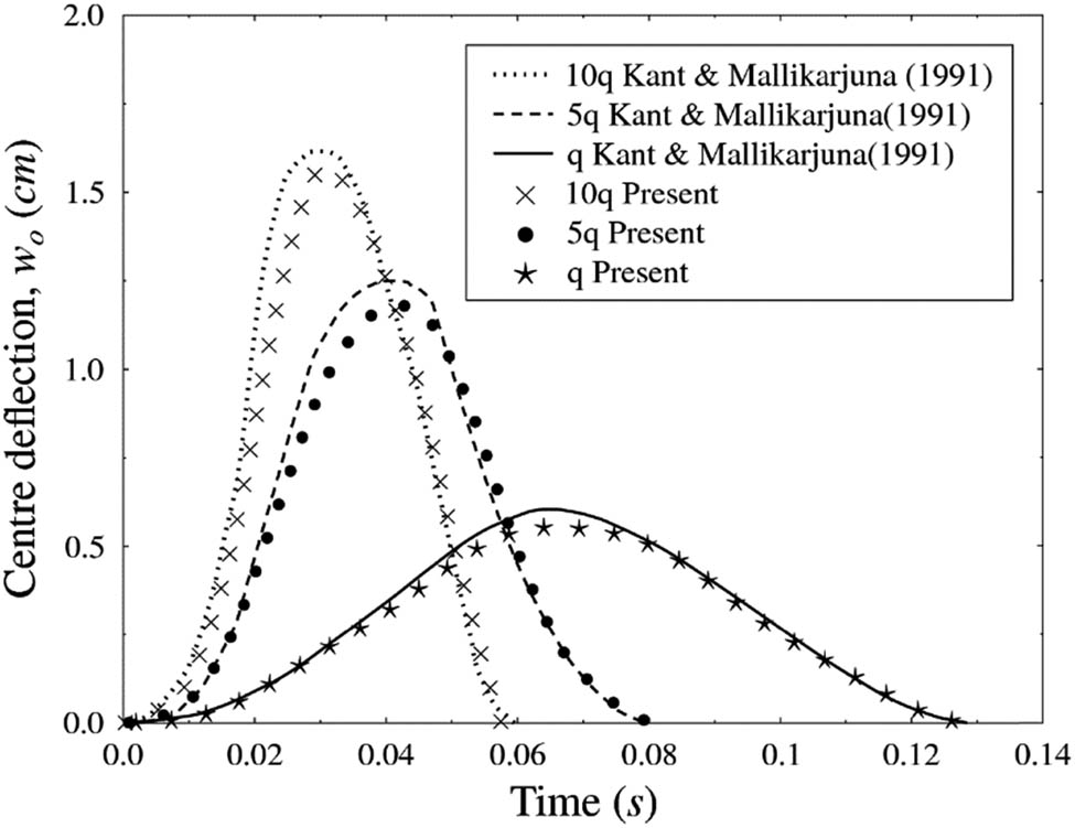
Comparison of nonlinear transient responses of isotropic square plates under suddenly applied uniformly distributed pulse loading.
Comparison of non-dimensional central deflection w̄ = wE m t 3 × 10³/(qb 4) for cross-ply [0°/90°/0°/90°/0°] square laminated CNTRC plates with different values of CNT volume fraction
| V cnt | Boundary conditions | |||||
|---|---|---|---|---|---|---|
| SSSS | CCCC | CFFF | ||||
| Ref. [26] | Present | Ref. [26] | Present | Ref. [26] | Present | |
| 0.11 | 7.3234 | 7.575 | 3.8306 | 3.725 | 28.6211 | 28.375 |
| 0.14 | 6.3455 | 6.475 | 3.506 | 3.4 | 24.8896 | 24.175 |
| 0.17 | 4.7024 | 4.875 | 2.4289 | 2.365 | 18.3666 | 18.3 |
Figure 5 shows the comparison of time histories of the square laminate with Reddy [23], Mallikarjun and Kant [27], and Zhang and Xiao [4]. It can be observed from the plot that the curve from the present result agrees well with the previous studies.
![Figure 5
Comparison of linear dynamic responses of square laminated [0°/90°/0°] clamped plate.](/document/doi/10.1515/ntrev-2022-0079/asset/graphic/j_ntrev-2022-0079_fig_005.jpg)
Comparison of linear dynamic responses of square laminated [0°/90°/0°] clamped plate.
4.2 CNTFPC panel
A square shell structure with sides 1 m and a thickness of 10 mm is used for the analyses. Table 4 shows the detailed mechanical properties of the CNT, resin, and fibers used for the numerical examples. A multi-scale analysis is performed for the effective material properties of the CNTFPC tabulated in Table 5 assuming volume fraction of fiber as 0.8.
Mechanical and geometrical properties of the materials used for CNTFPC panel
| Material | Source | Symbol | Value | Definition |
|---|---|---|---|---|
| Epoxy resin | Kim et al. [28] | E re | 2.72 GPa | Young’s modulus of epoxy resin |
| ρ re | 1,200 kg/m3 | Mass density of epoxy resin | ||
| ν re | 0.33 | Poisson’s ratio of epoxy resin | ||
| SWCNT | Han and Elliott [29] |
|
640 GPa | Young’s modulus of SWCNT |
|
|
10 GPa | Young’s modulus of SWCNT | ||
|
|
17.2 GPa | Shear modulus of SWCNT | ||
| ρ cnt | 1,350 kg/m3 | Mass density of SWCNT | ||
| ν cnt | 0.33 | Poisson’s ratio of SWCNT | ||
| t cnt | 0.34 nm | Thickness of SWCNT | ||
| d cnt | 1.4 nm | Diameter of SWCNT | ||
| l cnt | 25 μm | Length of SWCNT | ||
| E-glass fiber | Kim et al. (2009) | E f | 69 GPa | Young’s modulus of E-glass fiber |
| ρ f | 1,200 kg/m3 | Mass density of E-glass fiber | ||
| ν f | 0.2 | Poisson’s ratio of E-glass fiber |
Mechanical properties of CNTFPC panels for increased CNT weight ratios using multi-scale analysis
| CNT weight ratio | ρ (kg/m3) | E 11 (GPa) | E 22 (GPa) | G (GPa) |
|---|---|---|---|---|
| 0.00 | 1,224 | 55.8 | 34.5 | 12.8 |
| 0.01 | 1,225 | 56.3 | 42.4 | 16.3 |
| 0.02 | 1,227 | 56.7 | 46.8 | 18.2 |
| 0.03 | 1,228 | 57.2 | 49.6 | 19.5 |
| 0.04 | 1,229 | 57.7 | 51.7 | 20.5 |
| 0.05 | 1,231 | 58.1 | 53.2 | 21.2 |
| 0.06 | 1,232 | 58.6 | 54.5 | 21.8 |
| 0.07 | 1,233 | 59.1 | 55.6 | 22.3 |
| 0.08 | 1,235 | 59.5 | 56.6 | 22.7 |
Theoretical and experimental results of SWCNT have shown the Young’s modulus to be up to 600 GPa and tensile strength of 50–200 GPa [29]. It has longitudinal Young’s modulus of approximately 300 times larger than that of epoxy resin, and approximately 10 times larger than that of glass fiber as shown in Table 4. For this reason, properties of CNTFPC panels are improved for increased CNT weight ratios as shown in Table 5. The effect of the CNT weight ratio is studied from 0.00 to 0.08 at an interval of 0.01. Panels with R/a ratios of ∞ (flat plate), 0.8, 0.55, 0.4, and 0.32 are considered. Layup sequences in the same thickness of 10 mm considered are [0°/90°], [0°/90°/90°/0°], [0°/90°/0°/90°], [45°/−45°], [45°/−45°/45°/−45°], and [45°/−45°/−45°/45°]. Figure 6 shows the central cutout sizes of c/a = 0.1, 0.2, 0.4, and 0.6 considered in the study.
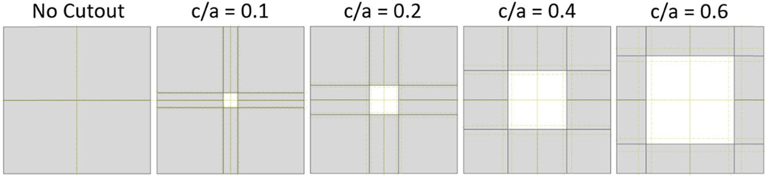
Panels with and without central cutout.
In frequency analysis, the following effects are considered: CNT weight ratio, R/a ratio, layup sequence, size of the cutout, and mode shapes. Figure 7 represents the variation in fundamental frequency due to different R/a ratios of the panel [0°/90°] under different CNT weight ratios. As the R/a ratio of the panel decreases, the frequency increases significantly. This is possibly due to the membrane force which increases with the decrease in R/a ratio. Besides, it is also observed that for all geometric shapes, as the CNT weight ratio increases, the frequency also increases. It shows that the panel’s stiffness increases when the CNT weight ratio is higher. It can also be seen that the increase in frequency is not linear and the rate decreases as the CNT weight ratio increases for all the geometric shapes. As CNT is still very expensive, adding more CNT is not beneficial. To investigate the change in frequency due to CNT weight ratio from 0.00 to 0.08 for R/a = 0.32, the percentage increase in the frequencies is 6.38, 2.95, 1.82, 1.28, 0.95, 0.81, 0.69, and 0.57%, respectively, showing that the addition of CNT weight ratio less than 0.02 would be better considering the cost.
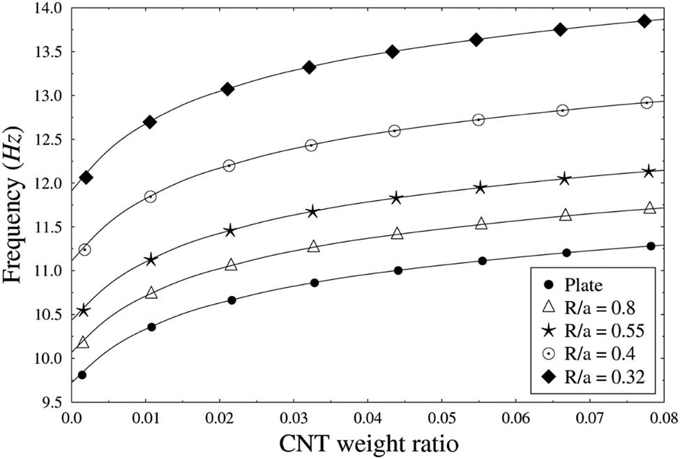
Induced natural frequencies of CNTFPC cylindrical panels for different SWCNT weight ratios and R/a ratios.
Figure 8 illustrates the effect of different layup sequences on the frequency of the flat panel with different CNT weight ratios. It can be observed that different layup sequences exhibit different frequencies. The layup sequence [0°/90°/90°/0°] exhibits the highest frequency among the six different layup sequences that are assumed. The results indicate that the effect of the layup sequence is significant on the stiffness of the panel. Table 6 lists the frequencies of flat panel [0°/90°] with different c/a ratios and CNT weight ratios. It is observed that the frequency decreases with the increase in c/a ratio and the frequency lost due to the cutout can be recovered by the addition of CNT. For example, the frequency of the panel with cutout size ratio c/a = 0.4 with no CNT is 8.9472 Hz. With the addition of CNT weight ratio 0.02, the frequency is increased to 9.7978 Hz which is close to the frequency of the panel with no cutout and no CNT. It shows that the effect of the CNT weight ratio is significant to recover the frequency lost from a cutout in laminated composite plates [30]. Figure 9 shows the mode shapes of a [0°/90°] composite square plate without and with 1% CNT weight ratio. It can be observed that the mode shapes of the plate are significantly different with different cutout sizes in both the figures. However, no significant changes are seen in the mode shapes when CNT is added to the plate.
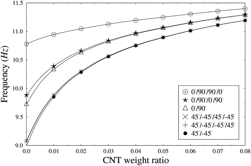
Induced natural frequencies of CNTFPC flat panels for different SWCNT weight ratios and layup sequences.
Natural frequencies of CNTFPC flat panels with and without cutout for increased SWCNT weight ratios
| CNT weight ratio | No cutout | c/a = 0.1 | c/a = 0.2 | c/a = 0.4 | c/a = 0.6 |
|---|---|---|---|---|---|
| 0.00 | 9.7224 | 9.6964 | 9.5924 | 8.9472 | 7.7300 |
| 0.01 | 10.332 | 10.304 | 10.195 | 9.5177 | 8.2271 |
| 0.02 | 10.631 | 10.603 | 10.491 | 9.7978 | 8.4713 |
| 0.03 | 10.822 | 10.793 | 10.68 | 9.9766 | 8.6271 |
| 0.04 | 10.959 | 10.930 | 10.816 | 10.105 | 8.7389 |
| 0.05 | 11.062 | 11.033 | 10.917 | 10.201 | 8.8226 |
| 0.06 | 11.151 | 11.122 | 11.005 | 10.284 | 8.8946 |
| 0.07 | 11.227 | 11.198 | 11.081 | 10.355 | 8.9568 |
| 0.08 | 11.291 | 11.262 | 11.144 | 10.415 | 9.0082 |
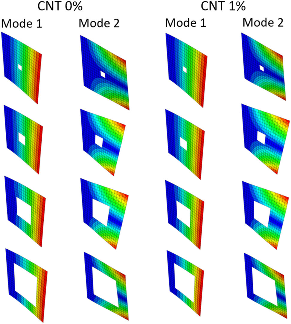
Mode shapes of CNTFPC flat panels with different cutout sizes for SWCNT 0% and 1%.
In the linear dynamic analysis, the following effects of CNTFPC cylindrical panel are investigated: R/a ratios and sizes of the cutout. Figure 10 shows the time histories of the panel [0°/90°] with no CNT for different R/a ratios. It can be observed that the deflection decreases with the decrease in R/a ratio. The reason for this is membrane force which increases with the decrease in the ratio. It can be concluded that stiffness increases with the increase in curvature resulting in lower deflection. Figure 11 depicts the effect of the central cutout sizes in the dynamic response of the composite plate [0°/90°] with no CNT. It is observed that the deflections till c/a = 0.2 are almost the same and increases when c/a ratio is beyond 0.2. When cutouts are introduced to a structure, mass as well as stiffness of the structure change simultaneously. This is the reason for no significant change till c/a = 0.2. It can be concluded that c/a ratio greater than 0.2 is not desirable for use due to higher deflection with the parameters considered in the study.
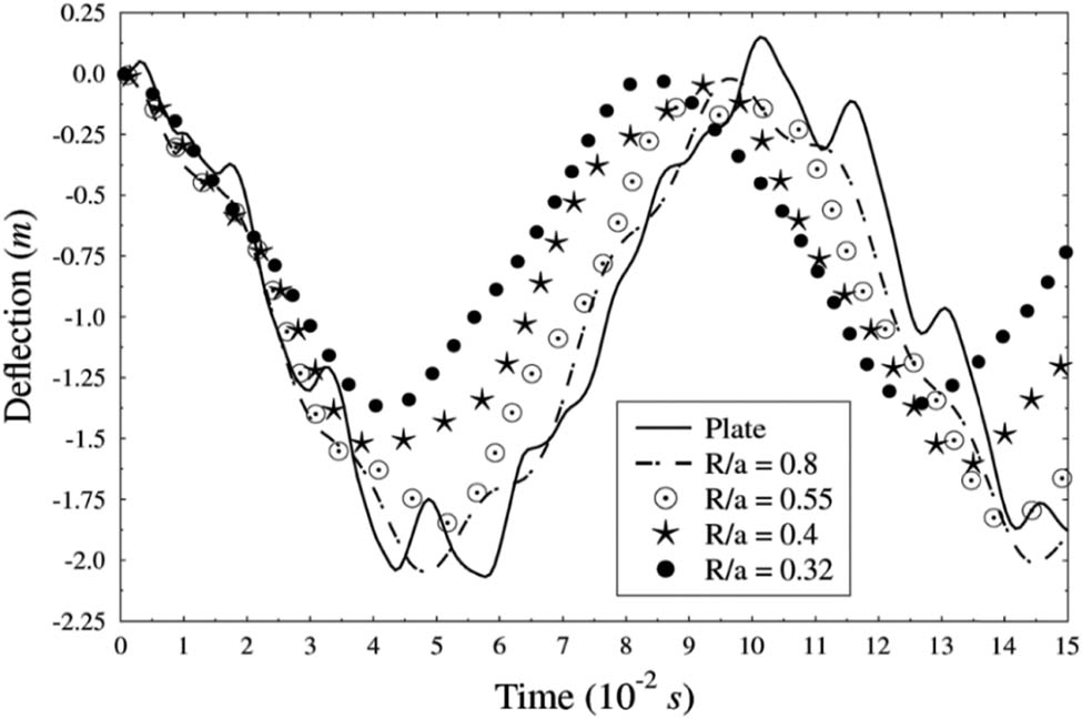
Linear dynamic time histories of CNTFPC cylindrical panels for different R/a ratios.

Linear dynamic time histories of CNTFPC flat panels for different central cutout sizes.
In the nonlinear dynamic analysis, the following effects of CNTFPC cylindrical panel are investigated: CNT weight ratio and layup angle sequence. Also, load–deflection curves using linear and nonlinear dynamic analyses are compared. Figure 12 shows the deflections of CNTFPC cylindrical panels [0°/90°] with R/a = 0.32 for different SWCNT weight ratios. It can be observed that the deflection decreases with the increase in CNT weight ratio showing that the panel gets stiffer with the increase in CNT weight ratio. Besides, it is also observed that the rate of decrease in deflection decreases with the increase in CNT weight ratio. Therefore, it is concluded that the addition of CNT weight ratio of more than 2% is not beneficial considering the cost. Figure 13 depicts the time histories for different layup sequences of the panel with R/a ratio 0.32 and no CNT. It can be seen that different layup sequences exhibit different deflections showing that the effect of the layup sequence is significant on the stiffness of the panel. It is found that the panel with layup sequence of [0°/90°/90°/0°] is the stiffest exhibiting the least deflection among the six layup sequences considered in the study.

Nonlinear dynamic time histories of CNTFPC cylindrical panels for different SWCNT weight ratios.
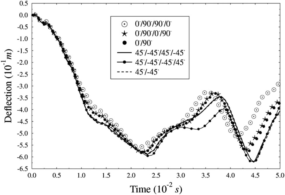
Nonlinear dynamic time histories of CNTFPC cylindrical panels for different layup angle sequences.
The load–deflection curves using linear and nonlinear dynamic analyses for a CNTFPC flat panel [0°/90°] with CNT weight ratio 1% is depicted in Figure 14. In linear dynamic analysis, there is a linear relationship between applied loads and deflections as it is assumed that the stresses remain in the linear elastic range of the used material, while in nonlinear dynamic analysis, there is a nonlinear relation as nonlinear effects can originate from geometrical nonlinearity (i.e., large deformations), material nonlinearity (i.e., elasto-plastic material), and contact. In this case, the nonlinear effect is related to geometrical nonlinearity. While linear dynamic analysis is simple, reduces time, and effort, it does not consider the nonlinearities concluding that nonlinear dynamic analysis is an accurate estimation technique.
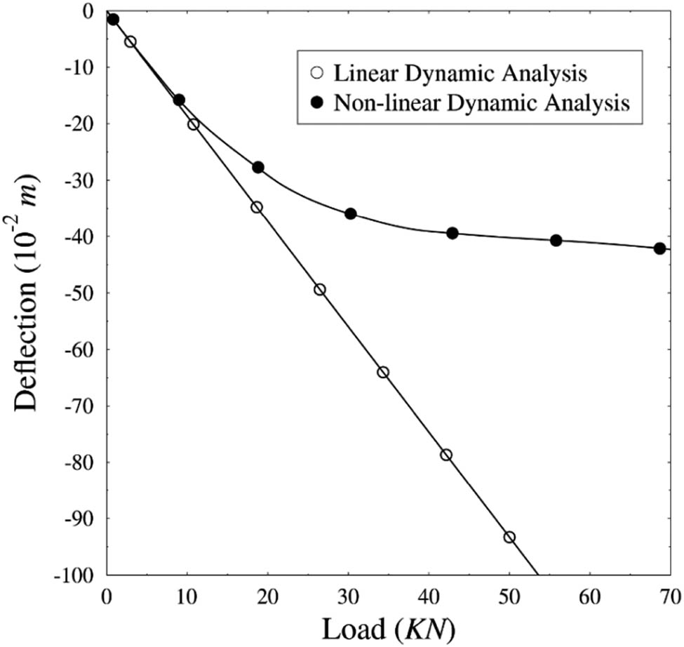
Load–deflection curves of CNTFPC flat panels using linear and nonlinear dynamic analyses.
4.3 Concrete beam reinforced with CNTFPC rebars
In order to validate the procedure for more complex and practical conditions, we apply the method to a concrete beam reinforced with CNTFPC rebars. The reinforced concrete beam of length (L) 5,500 mm, breadth 300 mm, and height 600 mm is modeled. Longitudinal rebars of diameter 19 mm and stirrups of diameter 8.0 mm are used. Three top and four bottom longitudinal bars are provided. The spacing of stirrups for L/3 length at the sides is 100 mm c/c and the spacing at the middle is 150 mm c/c. The details of the arrangement of the rebars are shown in Figure 15. The experimental mechanical properties of MWNTs/phenolic composites (CNTRC) from a study by Yeh et al. [31] are shown in Table 7. The mechanical properties of electrical/chemical resistance (ECR) – glass fiber are shown in Table 8. In the restricted scope of our study, our research focuses on the nonlinear dynamic and crack behaviors of curved panels with a cutout or CNTFPC-rebar type reinforced concrete beams.
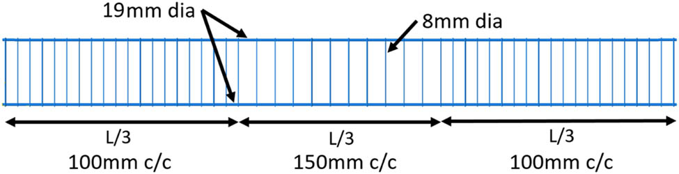
Details of the rebars in concrete beam.
Experimental mechanical properties of MWNTs/phenolic composites (CNTRC) from ref. [29] used for CNTFPC rebar
| CNT weight ratio (%) | 0 | 0.5 | 1.0 | 1.5 | 2.0 | 3.0 | 4.0 |
| Young’s modulus (GPa) | 5.13 | 5.65 | 6.4 | 6.88 | 6.96 | 7.25 | 7.53 |
| Tensile strength (MPa) | 42.32 | 50.29 | 60.15 | 59.89 | 63.03 | 64.30 | 69.66 |
Mechanical properties of E-glass fiber used for CNTFPC rebar
| Material | Value | Unit | Definition |
|---|---|---|---|
| Advantex® ECR glass | 81 | GPa | Young’s modulus of ECR glass |
| 2,620 | kg/m3 | Mass density of ECR glass | |
| 0.2 | Poisson’s ratio of ECR glass | ||
| 3,751 | MPa | Tensile strength of ECR glass |
The multi-scale analysis is used to calculate the effective mechanical properties of the CNTFPC rebars tabulated in Table 9 for different CNT weight ratios assuming volume fraction of fiber as 0.55. It can be observed that the enhancement of the mechanical properties due to CNT is low. Concrete properties used in this study are tabulated in Table 10. The boundary condition is simply supported in all cases. Tensile tests of the rebars of 240 mm length with different CNT weight ratios are carried out. The rebars are fixed at one end and the load is applied on the other end. Table 11 shows the maximum elongations and loads necessary for the failure of the rebars. It can be observed that the maximum elongation of the rebar decreases, while the maximum load increases as the CNT weight ratios increases. The elongation is decreased by 1.67% and the applied load is increased by 0.6% when a 4% CNT weight ratio is added to the rebar. Therefore, it is concluded that CNT contributes to the stiffness of the rebar, hence, enhancing its performance.
Mechanical properties of CNTFPC rebar for different CNT weight ratios using multi-scale analysis
| CNT wt(%) | E 11 (MPa) | E 22 (MPa) | G (MPa) | ρ (tons/mm3) | ν 12 | Tensile strength (MPa) |
|---|---|---|---|---|---|---|
| 0 | 46858.5 | 18394.211 | 5789.121 | 1.905 × 10⁻⁹ | 0.2585 | 2082.09 |
| 0.5 | 47092.5 | 19769.673 | 6276.844 | 1.905 × 10⁻⁹ | 0.2585 | 2085.68 |
| 1 | 47,430 | 21645.323 | 6954.827 | 1.905 × 10⁻⁹ | 0.2585 | 2090.12 |
| 1.5 | 47,646 | 22784.369 | 7373.835 | 1.906 × 10⁻⁹ | 0.2585 | 2090.00 |
| 2 | 47,682 | 22969.848 | 7442.586 | 1.906 × 10⁻⁹ | 0.2585 | 2091.41 |
| 3 | 47812.5 | 23632.183 | 7689.282 | 1.907 × 10⁻⁹ | 0.2585 | 2091.99 |
| 4 | 47938.5 | 24257.223 | 7923.791 | 1.908 × 10⁻⁹ | 0.2585 | 2094.40 |
Material properties of concrete used in this study
| Properties | Definition | Value | Unit |
|---|---|---|---|
| Density | Mass density | 2,500 | kg/m3 |
| Elastic properties | Young’s modulus | 29,000 | MPa |
| Poisson’s ratio | 0.18 | ||
| Strain at compressive strength | 0.002 | ||
| Compressive behavior | Yield stress | 20 | MPa |
| Inelastic strain | 0 | ||
| Uniaxial compressive strength (%) | 37 | MPa | |
| Tensile behavior | Yield stress | 1.8 | MPa |
| Crack strain | 0 | ||
| Tensile strength | 3.7 | MPa | |
| Strain at end of yield plateau | 0.0002 |
Results of the tensile test of rebars
| CNT (wt%) | Maximum elongation (mm) | Difference (%) | Maximum load (N) | Difference (%) |
|---|---|---|---|---|
| 0 | 10.664 | −0.33 | 590,333.5 | 0.17 |
| 0.5 | 10.629 | −0.50 | 591,350.4 | 0.21 |
| 1 | 10.576 | −0.46 | 592,608.4 | −0.01 |
| 1.5 | 10.528 | −0.01 | 592,575.2 | 0.07 |
| 2 | 10.527 | −0.25 | 592,975.8 | 0.03 |
| 3 | 10.501 | −0.15 | 593,137.9 | 0.12 |
| 4 | 10.485 | 593,821.7 |
Table 12 shows the natural frequencies of the five modes of the beam which is reinforced by rebars with the CNT weight ratios of 0, 0.5, 1, 1.5, 2, 3, and 4%. It is observed that the natural frequencies increase with the increase in the CNT weight ratio. This is because the rebars get stiffer with the increase in the CNT weight ratio. While there is an increase in the frequency of the beam, the change is insignificant as the enhancement of the mechanical properties of CNTFPC rebars due to CNT is low. Table 13 shows the maximum deflection of the beam reinforced with different CNT weight ratio rebars using linear static analysis. A uniformly distributed static load of magnitude 0.13 MPa is applied and the beam is not conditioned to crack. It can be observed that the deflection decreases with the increase in the CNT weight ratio which is due to the stiffness effect of the CNT on the CNTFPC rebars. However, the change in deflection of the beam is very low as the enhancement of mechanical properties of CNTFPC due to CNT is low and concrete must crack before the rebar can take up most of the tensile stresses.
Natural frequencies of the beam with different CNT weight ratio rebars
| Mode (Hz) | CNT weight ratio | ||||||
|---|---|---|---|---|---|---|---|
| 0 | 0.005 | 0.01 | 0.015 | 0.02 | 0.03 | 0.04 | |
| 1 | 16.092 | 16.093 | 16.096 | 16.097 | 16.097 | 16.098 | 16.099 |
| 2 | 28.627 | 28.63 | 28.635 | 28.638 | 28.638 | 28.64 | 28.641 |
| 3 | 53.001 | 53.009 | 53.022 | 53.029 | 53.031 | 53.035 | 53.039 |
| 4 | 57.109 | 57.114 | 57.122 | 57.127 | 57.127 | 57.13 | 57.133 |
| 5 | 78.073 | 78.091 | 78.116 | 78.131 | 78.134 | 78.143 | 78.152 |
Maximum deflection of the beam with different CNT weight ratio rebars under static loading
| CNT weight ratio (%) | Maximum deflection (mm) | Difference (%) |
|---|---|---|
| 0 | 15.886 | −0.74 |
| 0.5 | 15.768 | −0.22 |
| 1 | 15.733 | −0.36 |
| 1.5 | 15.677 | −0.06 |
| 2 | 15.667 | −0.59 |
| 3 | 15.575 | −0.21 |
| 4 | 15.543 |
As concrete must crack before the rebar can take up most of the tensile stresses, crack analysis is done for the beam reinforced with different CNT weight ratio rebars. Inelastic properties are included for the concrete while only elastic properties are used for the rebars to show an average difference in the deflection of the beam. The spacing of the stirrups is doubled and CNT weight ratios considered are 0.00, 0.01, 0.02, and 0.04. Figure 16 presents the load–deflection curve of the beam after the beam cracks. It is apparent that for any load applied on the beam, the deflection decreases with the increase in the CNT weight ratio. This is because the stiffness of the CNTFPC rebars increases when the CNT weight ratio rises. Besides, the deflection of the beam at load 2,700 kN is tabulated in Table 14. It can be seen from the table that when the CNT weight ratios are increased from 0 to 1%, 1 to 2%, and 2 to 4%, there is an approximate reduction in the deflection of the beam by 2.62, 1.89, and 4.91%, respectively. This result indicates that the effect of the CNT weight ratio in the rebars is significant for the reduction in beam deflection.
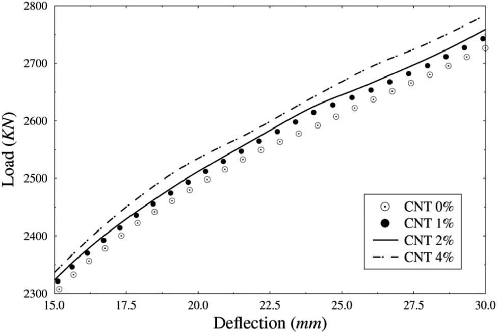
Load–deflection curve of the beam with different CNT weight ratio rebars after the beam cracks.
Deflection of the beam at load 2,700kN
| CNT weight ratio % | Deflection (mm) | Difference (%) |
|---|---|---|
| 0 | 28.9032 | −2.62 |
| 1 | 28.1452 | −1.89 |
| 2 | 27.6129 | −4.91 |
| 4 | 26.2581 |
Figure 17 shows the severity of cracks in the entire beam for different CNT weight ratios in the rebars. Inelastic properties are considered for both the concrete as well as rebars. The spacing of stirrups is doubled. It can be observed that the width of the cracks in the beam decreases when the CNT weight ratio increases. Also, Table 15 shows the maximum crack width at the bottom center of the beam when a load of 1,150 kN is applied. It can be seen from the table that the crack width decreases by 4.26, 0.89, and 0.69% in the linear region, while in the nonlinear region, the crack width increases by 2.41% at first and later decreases by 3.46 and 7.53% when CNT weight ratios are increased from 0 to 1%, 1 to 2%, and 2 to 4%, respectively. Although the enhancement of the mechanical properties of the rebar due to CNT is low, the increment in Young’s modulus and tensile strength contributes to the reduction in the crack width of the overall beam. It can be concluded from the results that CNT plays an important role in reducing the crack width of the overall beam.
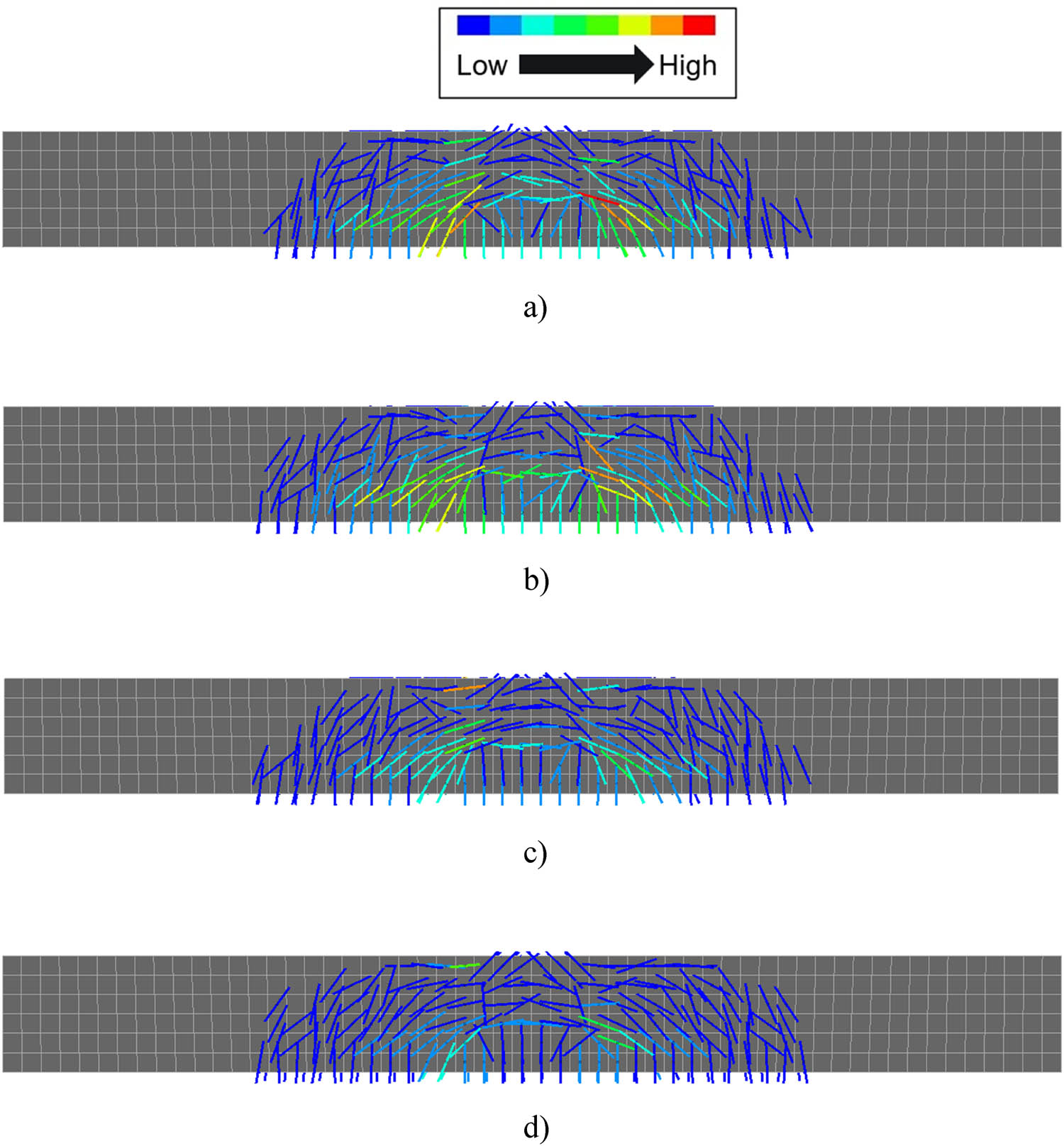
Crack images of beam reinforced with CNTFPC rebars. (a) CNT weight ratio of 0.00, (b) CNT weight ratio of 0.01, (c) CNT weight ratio of 0.02, and (d) CNT weight ratio of 0.04.
Crack width at the bottom center of the beam (load = 1,150 kN)
| CNT wt% | Crack at linear region (mm) | Difference (%) | Crack at nonlinear region (mm) | Difference (%) |
|---|---|---|---|---|
| 0 | 0.379 | −4.26 | 1.1387 | 2.41 |
| 1 | 0.3629 | −0.89 | 1.1661 | −3.46 |
| 2 | 0.3597 | −0.69 | 1.1258 | −7.53 |
| 4 | 0.3572 | 1.0411 |
5 Summary and conclusion
In this study, we applied the modified Halpin–Tsai model to estimate the effective material properties of CNTFPC reinforced structures for various geometries. An intuitive prediction of the nonlinear dynamic behavior of composite structures reinforced by CNTFPC is difficult because of their complexity due to the combined effect of anisotropy and geometry. The effects of the CNT are shown by performing the natural frequency, linear dynamic, and nonlinear dynamic analyses of CNTFPC panels, and linear static and crack analyses of CNTFPC rebar reinforced concrete beams. We find the following key observations in designing structures reinforced by CNTFPC:
The tensile test for examining the performance of the CNTFPC rebars with different CNT weight ratios showed that the elongation of the rebar decreases and the load necessary for the failure of rebar increases with the increase in the CNT weight ratio. The elongation decreased by 1.67% and applied load increased by 0.6% when a 4% CNT weight ratio is added in the rebars. Thus, CNT increases the stiffness of the rebar resulting in enhancement of its performance.
In frequency analysis, the change in frequencies of all the five modes of the beam for different CNT weight ratios in the rebars is low. The same trend can be seen for linear static analysis where the change in deflection of the beam is low. The mechanical enhancements due to CNT in the rebars are low to bring significant change in these cases. It should be noted that the reinforcements used in the study are passive and resist most of the loads only after the concrete starts cracking. As the concrete is not conditioned to crack in both the analyses, the change in the results is low.
The crack analysis with inelastic concrete and elastic rebar properties showed the average reduction in the deflections of the beam to be 2.6, 1.8, and 4.9% when the CNT weight ratio in the rebar is increased from 0 to 1%, 1 to 2%, and 2 to 4%, respectively, which shows that higher CNT content in the rebar is better for lowering the deflection of the beam.
In the case of the crack width of the overall beam, a significant reduction in the crack width is seen as the CNT weight ratio increases in the rebars. Moreover, the crack width at the bottom center of the beam at a load of 1,150 kN is lowered by approximately 5.7% in the linear region and 8.5% in the nonlinear region when a 4% CNT weight ratio is added to the rebar. Although the enhancement of the mechanical properties of the rebar due to CNT is low, the increment in Young’s modulus and tensile strength contributes to the reduction in the crack width of the beam. CNT shows significant results for tensile tests, deflection of the beam after the concrete cracks, and reduction in crack width of the overall beam.
In conclusion, this study analyzed the effect of CNT on composite material and compared the structural performance of the beam reinforced with the CNTFPC rebars for different CNT weight ratios through finite element analysis. However, the results of this study are limited because the analyses are performed through finite element analysis with limited cases. It will be necessary to prove the mechanism of action of CNT and fiber from further experimental studies such as SEM images, FTIR or Raman, and XRD analyses.
-
Funding information: This work was supported by the National Research Foundation of Korea (NRF) grant funded by the Korea government (MSIP) (no. 2018R1D1A1B07050080).
-
Author contributions: All authors have accepted responsibility for the entire content of this manuscript and approved its submission.
-
Conflict of interest: The authors state no conflict of interest.
References
[1] Zhang LW, Lei ZX, Liew KM, Yu JL. Large deflection geometrically nonlinear analysis of carbon nanotube-reinforced functionally graded cylindrical panels. Comput Methods Appl Mech Eng. 2014;273:1–18. 10.1016/j.cma.2014.01.024.Search in Google Scholar
[2] Lei ZX, Zhang LW, Liew KM, Yu JL. Dynamic stability analysis of carbon nanotube-reinforced functionally graded cylindrical panels using the element-free kp-Ritz method. Composite Struct. 2014;113:328–38. 10.1016/j.compstruct.2014.03.035.Search in Google Scholar
[3] Mirzaei M, Kiani Y. Free vibration of functionally graded carbon nanotube reinforced composite cylindrical panels. Composite Struct. 2016;142:45–56. 10.1016/j.compstruct.2015.12.071.Search in Google Scholar
[4] Zhang LW, Xiao LN. Mechanical behavior of laminated CNT-reinforced composite skew plates subjected to dynamic loading. Compos Part B: Eng. 2017;122:219–30. 10.1016/j.compositesb.2017.03.041.Search in Google Scholar
[5] Kiani Y. Analysis of FG-CNT reinforced composite conical panel subjected to moving load using Ritz method. J Therm Stresses. 2017a;40:1442–60. 10.1080/01495739.2017.1336742.Search in Google Scholar
[6] Kiani Y. Thermal buckling of temperature-dependent FG-CNT-reinforced composite skew plates. Thin-Walled Struct. 2017b;119:47–57. 10.1016/j.tws.2017.05.03.Search in Google Scholar
[7] Kiani Y, Mirzaeib M. Rectangular and skew shear buckling of FG-CNT reinforced composite skew plates using Ritz method. Aerosp Sci Technol. 2018;77:388–98. 10.1016/j.ast.2018.03.022.Search in Google Scholar
[8] Rafiee M, Liu XF, He XQ, Kitipornchai S. Geometrically nonlinear free vibration of shear deformable piezoelectric carbon nanotube/fiber/polymer multiscale laminated composite plates. J Sound Vib. 2014;333(14):3236–51. 10.1016/j.jsv.2014.02.033.Search in Google Scholar
[9] Lee SY. Dynamic instability assessment of carbon nanotube/fiber/polymer multiscale composite skew plates with delamination based on HSDT. Composite Struct. 2018;200:757–70. 10.1016/j.compstruct.2018.05.121.Search in Google Scholar
[10] Lee S, Hwang J. Finite element nonlinear transient modelling of carbon nanotubes reinforced fiber/polymer composite spherical shells with a cutout. Nanotechnol Rev. 2019;8(1):444–51. 10.1515/ntrev-2019-0039.Search in Google Scholar
[11] Ahmadi M, Ansari R, Rouhi H. Free and forced vibration analysis of rectangular-circular-annular plates made of carbon fiber-carbon nanotube-polymer hybrid composites. Sci Eng Compos Mater. 2019a;2019:70–6. 10.1515/secm-2017-0279.Search in Google Scholar
[12] Ahmadi M, Ansari R, Rouhi H. Fracture behavior of the carbon nanotube/carbon fiber/polymer multiscale composites under bending test – A stochastic finite element method. Mech Adv Mater Struct. 2019b;26:1169–77. 10.1080/15376494.2018.1432790.Search in Google Scholar
[13] Ahmadi M, Ansari R, Rouhi H. On the free vibrations of piezoelectric carbon nanotube-reinforced microbeams: a multiscale finite element approach. Iran J Sci Technol Trans Mech Eng. 2019c;43:285–94. 10.1007/S40997-018-0157-X.Search in Google Scholar
[14] Ahmadi M, Ansari R, Rouhi H. Free vibration analysis of carbon fiber-carbon nanotube-polymer matrix composite plates by a finite element-based multi-scale modeling approach. J Multiscale Model. 2018;9:1850002. 10.1142/S1756973718500026.Search in Google Scholar
[15] Ahmadi M, Ansari R, Rouhi H. Multi-scale bending, buckling and vibration analyses of carbon fiber/carbon nanotube-reinforced polymer nanocomposite plates with various shapes. Phys E Low-Dimensional Syst Nanostructures Multiscale Model. 2017;93:17–25. 10.1016/j.physe.2017.05.009.Search in Google Scholar
[16] Lee S. Dynamic stability and nonlinear transient behaviors of CNT-reinforced fiber/polymer composite cylindrical panels with delamination around a cutout. Nonlinear Dyn. 2020;99:2551–69. 10.1007/s11071-020-05477-x.Search in Google Scholar
[17] Chaallal O, Benmokrane B. Fiber-reinforced plastic rebars for concrete applications. Compos Part B Eng. 1996;27(3–4):245–52. 10.1016/1359-8368(95)00023-2.Search in Google Scholar
[18] Wang H, Belarbi A. Ductility characteristics of fiber-reinforced-concrete beams reinforced with FRP rebars. Constr Build Mater. 2011;25(5):2391–401. 10.1016/j.conbuildmat.2010.11.040.Search in Google Scholar
[19] Inman M, Thorhallsson ER, Azrague K. A mechanical and environmental assessment and comparison of basalt fibre reinforced polymer (BFRP) rebar and steel rebar in concrete beams. Energy Procedia. 2017;111:31–40. 10.1016/j.egypro.2017.03.005.Search in Google Scholar
[20] Duic J, Kenno S, Das S. Performance of concrete beams reinforced with basalt fibre composite rebar. Constr Build Mater. 2018;176:470–81. 10.1016/j.conbuildmat.2018.04.208.Search in Google Scholar
[21] Gojny FH, Wichmann MHG, Köpke U, Fiedler B, Schulte K. Carbon nanotube-reinforced epoxy-composites enhanced stiffness and fracture toughness at low nanotube content. Compos Sci Technol. 2004;64(15):2363–71. 10.1016/j.compscitech.2004.04.002.Search in Google Scholar
[22] Hewitt RL, Malherbe MC. An approximation for the longitudinal shear modulus of continuous fiber composites. J Composite Mater. 1970;4(2):280–2. 10.1177/002199837000400214.Search in Google Scholar
[23] Reddy JN. Dynamic (transient) analysis of layered anisotropic composite material plates. Int J Numer Methods Eng. 1983;19(2):237–55. 10.1002/nme.1620190206.Search in Google Scholar
[24] Sahu SK, Datta PK. Dynamic stability of curved panels with cutouts. J Sound Vib. 2002;251(4):683–96. 10.1006/jsvi.2001.3961.Search in Google Scholar
[25] Sivasubramonian B, Rao GV, Krishnan A. Free vibration of longitudinally stiffened curved panels with cutout. J Sound Vib. 1999;226(1):41–55. 10.1006/jsvi.1999.2281.Search in Google Scholar
[26] Lei ZX, Zhang LW, Liew KM. Analysis of laminated CNT reinforced functionally graded plates using the element-free kp-Ritz method. Compos Part B: Eng. 2016;84:211–21. 10.1016/j.compositesb.2015.08.081.Search in Google Scholar
[27] Mallikarjuna, Kant T. Dynamics of laminated composite plates with a higher order theory and finite element discretization. J Sound Vib. 1988;126(3):463–75. 10.1016/0022-460X(88)90224-6.Search in Google Scholar
[28] Han Y, Elliott J. Molecular dynamics simulations of the elastic properties of polymer/carbon nanotube composites. Comput Mater Sci. 2007;39(2):315–23. 10.1016/j.commatsci.2006.06.011.Search in Google Scholar
[29] Kim M, Park YB, Okoli OI, Zhang C. Processing, characterization, and modeling of carbon nanotube-reinforced multiscale composites. Compos Sci Technol. 2009;69(3–4):335–42. 10.1016/j.compscitech.2008.10.019.Search in Google Scholar
[30] Lee SY, Park T. Free vibration of laminated composite skew plates with central cutouts. Struct Eng Mech. 2009;31(5):587–603. 10.12989/sem.2009.31.5.587.Search in Google Scholar
[31] Yeh MK, Tai NH, Liu JH. Mechanical behavior of phenolic-based composites reinforced with multi-walled carbon nanotubes. Carbon. 2006;44(1):1–9. 10.1016/j.carbon.2005.07.005.Search in Google Scholar
© 2022 Ashish Maharjan et al., published by De Gruyter
This work is licensed under the Creative Commons Attribution 4.0 International License.
Articles in the same Issue
- Research Articles
- Theoretical and experimental investigation of MWCNT dispersion effect on the elastic modulus of flexible PDMS/MWCNT nanocomposites
- Mechanical, morphological, and fracture-deformation behavior of MWCNTs-reinforced (Al–Cu–Mg–T351) alloy cast nanocomposites fabricated by optimized mechanical milling and powder metallurgy techniques
- Flammability and physical stability of sugar palm crystalline nanocellulose reinforced thermoplastic sugar palm starch/poly(lactic acid) blend bionanocomposites
- Glutathione-loaded non-ionic surfactant niosomes: A new approach to improve oral bioavailability and hepatoprotective efficacy of glutathione
- Relationship between mechano-bactericidal activity and nanoblades density on chemically strengthened glass
- In situ regulation of microstructure and microwave-absorbing properties of FeSiAl through HNO3 oxidation
- Research on a mechanical model of magnetorheological fluid different diameter particles
- Nanomechanical and dynamic mechanical properties of rubber–wood–plastic composites
- Investigative properties of CeO2 doped with niobium: A combined characterization and DFT studies
- Miniaturized peptidomimetics and nano-vesiculation in endothelin types through probable nano-disk formation and structure property relationships of endothelins’ fragments
- N/S co-doped CoSe/C nanocubes as anode materials for Li-ion batteries
- Synergistic effects of halloysite nanotubes with metal and phosphorus additives on the optimal design of eco-friendly sandwich panels with maximum flame resistance and minimum weight
- Octreotide-conjugated silver nanoparticles for active targeting of somatostatin receptors and their application in a nebulized rat model
- Controllable morphology of Bi2S3 nanostructures formed via hydrothermal vulcanization of Bi2O3 thin-film layer and their photoelectrocatalytic performances
- Development of (−)-epigallocatechin-3-gallate-loaded folate receptor-targeted nanoparticles for prostate cancer treatment
- Enhancement of the mechanical properties of HDPE mineral nanocomposites by filler particles modulation of the matrix plastic/elastic behavior
- Effect of plasticizers on the properties of sugar palm nanocellulose/cinnamon essential oil reinforced starch bionanocomposite films
- Optimization of nano coating to reduce the thermal deformation of ball screws
- Preparation of efficient piezoelectric PVDF–HFP/Ni composite films by high electric field poling
- MHD dissipative Casson nanofluid liquid film flow due to an unsteady stretching sheet with radiation influence and slip velocity phenomenon
- Effects of nano-SiO2 modification on rubberised mortar and concrete with recycled coarse aggregates
- Mechanical and microscopic properties of fiber-reinforced coal gangue-based geopolymer concrete
- Effect of morphology and size on the thermodynamic stability of cerium oxide nanoparticles: Experiment and molecular dynamics calculation
- Mechanical performance of a CFRP composite reinforced via gelatin-CNTs: A study on fiber interfacial enhancement and matrix enhancement
- A practical review over surface modification, nanopatterns, emerging materials, drug delivery systems, and their biophysiochemical properties for dental implants: Recent progresses and advances
- HTR: An ultra-high speed algorithm for cage recognition of clathrate hydrates
- Effects of microalloying elements added by in situ synthesis on the microstructure of WCu composites
- A highly sensitive nanobiosensor based on aptamer-conjugated graphene-decorated rhodium nanoparticles for detection of HER2-positive circulating tumor cells
- Progressive collapse performance of shear strengthened RC frames by nano CFRP
- Core–shell heterostructured composites of carbon nanotubes and imine-linked hyperbranched polymers as metal-free Li-ion anodes
- A Galerkin strategy for tri-hybridized mixture in ethylene glycol comprising variable diffusion and thermal conductivity using non-Fourier’s theory
- Simple models for tensile modulus of shape memory polymer nanocomposites at ambient temperature
- Preparation and morphological studies of tin sulfide nanoparticles and use as efficient photocatalysts for the degradation of rhodamine B and phenol
- Polyethyleneimine-impregnated activated carbon nanofiber composited graphene-derived rice husk char for efficient post-combustion CO2 capture
- Electrospun nanofibers of Co3O4 nanocrystals encapsulated in cyclized-polyacrylonitrile for lithium storage
- Pitting corrosion induced on high-strength high carbon steel wire in high alkaline deaerated chloride electrolyte
- Formulation of polymeric nanoparticles loaded sorafenib; evaluation of cytotoxicity, molecular evaluation, and gene expression studies in lung and breast cancer cell lines
- Engineered nanocomposites in asphalt binders
- Influence of loading voltage, domain ratio, and additional load on the actuation of dielectric elastomer
- Thermally induced hex-graphene transitions in 2D carbon crystals
- The surface modification effect on the interfacial properties of glass fiber-reinforced epoxy: A molecular dynamics study
- Molecular dynamics study of deformation mechanism of interfacial microzone of Cu/Al2Cu/Al composites under tension
- Nanocolloid simulators of luminescent solar concentrator photovoltaic windows
- Compressive strength and anti-chloride ion penetration assessment of geopolymer mortar merging PVA fiber and nano-SiO2 using RBF–BP composite neural network
- Effect of 3-mercapto-1-propane sulfonate sulfonic acid and polyvinylpyrrolidone on the growth of cobalt pillar by electrodeposition
- Dynamics of convective slippery constraints on hybrid radiative Sutterby nanofluid flow by Galerkin finite element simulation
- Preparation of vanadium by the magnesiothermic self-propagating reduction and process control
- Microstructure-dependent photoelectrocatalytic activity of heterogeneous ZnO–ZnS nanosheets
- Cytotoxic and pro-inflammatory effects of molybdenum and tungsten disulphide on human bronchial cells
- Improving recycled aggregate concrete by compression casting and nano-silica
- Chemically reactive Maxwell nanoliquid flow by a stretching surface in the frames of Newtonian heating, nonlinear convection and radiative flux: Nanopolymer flow processing simulation
- Nonlinear dynamic and crack behaviors of carbon nanotubes-reinforced composites with various geometries
- Biosynthesis of copper oxide nanoparticles and its therapeutic efficacy against colon cancer
- Synthesis and characterization of smart stimuli-responsive herbal drug-encapsulated nanoniosome particles for efficient treatment of breast cancer
- Homotopic simulation for heat transport phenomenon of the Burgers nanofluids flow over a stretching cylinder with thermal convective and zero mass flux conditions
- Incorporation of copper and strontium ions in TiO2 nanotubes via dopamine to enhance hemocompatibility and cytocompatibility
- Mechanical, thermal, and barrier properties of starch films incorporated with chitosan nanoparticles
- Mechanical properties and microstructure of nano-strengthened recycled aggregate concrete
- Glucose-responsive nanogels efficiently maintain the stability and activity of therapeutic enzymes
- Tunning matrix rheology and mechanical performance of ultra-high performance concrete using cellulose nanofibers
- Flexible MXene/copper/cellulose nanofiber heat spreader films with enhanced thermal conductivity
- Promoted charge separation and specific surface area via interlacing of N-doped titanium dioxide nanotubes on carbon nitride nanosheets for photocatalytic degradation of Rhodamine B
- Elucidating the role of silicon dioxide and titanium dioxide nanoparticles in mitigating the disease of the eggplant caused by Phomopsis vexans, Ralstonia solanacearum, and root-knot nematode Meloidogyne incognita
- An implication of magnetic dipole in Carreau Yasuda liquid influenced by engine oil using ternary hybrid nanomaterial
- Robust synthesis of a composite phase of copper vanadium oxide with enhanced performance for durable aqueous Zn-ion batteries
- Tunning self-assembled phases of bovine serum albumin via hydrothermal process to synthesize novel functional hydrogel for skin protection against UVB
- A comparative experimental study on damping properties of epoxy nanocomposite beams reinforced with carbon nanotubes and graphene nanoplatelets
- Lightweight and hydrophobic Ni/GO/PVA composite aerogels for ultrahigh performance electromagnetic interference shielding
- Research on the auxetic behavior and mechanical properties of periodically rotating graphene nanostructures
- Repairing performances of novel cement mortar modified with graphene oxide and polyacrylate polymer
- Closed-loop recycling and fabrication of hydrophilic CNT films with high performance
- Design of thin-film configuration of SnO2–Ag2O composites for NO2 gas-sensing applications
- Study on stress distribution of SiC/Al composites based on microstructure models with microns and nanoparticles
- PVDF green nanofibers as potential carriers for improving self-healing and mechanical properties of carbon fiber/epoxy prepregs
- Osteogenesis capability of three-dimensionally printed poly(lactic acid)-halloysite nanotube scaffolds containing strontium ranelate
- Silver nanoparticles induce mitochondria-dependent apoptosis and late non-canonical autophagy in HT-29 colon cancer cells
- Preparation and bonding mechanisms of polymer/metal hybrid composite by nano molding technology
- Damage self-sensing and strain monitoring of glass-reinforced epoxy composite impregnated with graphene nanoplatelet and multiwalled carbon nanotubes
- Thermal analysis characterisation of solar-powered ship using Oldroyd hybrid nanofluids in parabolic trough solar collector: An optimal thermal application
- Pyrene-functionalized halloysite nanotubes for simultaneously detecting and separating Hg(ii) in aqueous media: A comprehensive comparison on interparticle and intraparticle excimers
- Fabrication of self-assembly CNT flexible film and its piezoresistive sensing behaviors
- Thermal valuation and entropy inspection of second-grade nanoscale fluid flow over a stretching surface by applying Koo–Kleinstreuer–Li relation
- Mechanical properties and microstructure of nano-SiO2 and basalt-fiber-reinforced recycled aggregate concrete
- Characterization and tribology performance of polyaniline-coated nanodiamond lubricant additives
- Combined impact of Marangoni convection and thermophoretic particle deposition on chemically reactive transport of nanofluid flow over a stretching surface
- Spark plasma extrusion of binder free hydroxyapatite powder
- An investigation on thermo-mechanical performance of graphene-oxide-reinforced shape memory polymer
- Effect of nanoadditives on the novel leather fiber/recycled poly(ethylene-vinyl-acetate) polymer composites for multifunctional applications: Fabrication, characterizations, and multiobjective optimization using central composite design
- Design selection for a hemispherical dimple core sandwich panel using hybrid multi-criteria decision-making methods
- Improving tensile strength and impact toughness of plasticized poly(lactic acid) biocomposites by incorporating nanofibrillated cellulose
- Green synthesis of spinel copper ferrite (CuFe2O4) nanoparticles and their toxicity
- The effect of TaC and NbC hybrid and mono-nanoparticles on AA2024 nanocomposites: Microstructure, strengthening, and artificial aging
- Excited-state geometry relaxation of pyrene-modified cellulose nanocrystals under UV-light excitation for detecting Fe3+
- Effect of CNTs and MEA on the creep of face-slab concrete at an early age
- Effect of deformation conditions on compression phase transformation of AZ31
- Application of MXene as a new generation of highly conductive coating materials for electromembrane-surrounded solid-phase microextraction
- A comparative study of the elasto-plastic properties for ceramic nanocomposites filled by graphene or graphene oxide nanoplates
- Encapsulation strategies for improving the biological behavior of CdS@ZIF-8 nanocomposites
- Biosynthesis of ZnO NPs from pumpkin seeds’ extract and elucidation of its anticancer potential against breast cancer
- Preliminary trials of the gold nanoparticles conjugated chrysin: An assessment of anti-oxidant, anti-microbial, and in vitro cytotoxic activities of a nanoformulated flavonoid
- Effect of micron-scale pores increased by nano-SiO2 sol modification on the strength of cement mortar
- Fractional simulations for thermal flow of hybrid nanofluid with aluminum oxide and titanium oxide nanoparticles with water and blood base fluids
- The effect of graphene nano-powder on the viscosity of water: An experimental study and artificial neural network modeling
- Development of a novel heat- and shear-resistant nano-silica gelling agent
- Characterization, biocompatibility and in vivo of nominal MnO2-containing wollastonite glass-ceramic
- Entropy production simulation of second-grade magnetic nanomaterials flowing across an expanding surface with viscidness dissipative flux
- Enhancement in structural, morphological, and optical properties of copper oxide for optoelectronic device applications
- Aptamer-functionalized chitosan-coated gold nanoparticle complex as a suitable targeted drug carrier for improved breast cancer treatment
- Performance and overall evaluation of nano-alumina-modified asphalt mixture
- Analysis of pure nanofluid (GO/engine oil) and hybrid nanofluid (GO–Fe3O4/engine oil): Novel thermal and magnetic features
- Synthesis of Ag@AgCl modified anatase/rutile/brookite mixed phase TiO2 and their photocatalytic property
- Mechanisms and influential variables on the abrasion resistance hydraulic concrete
- Synergistic reinforcement mechanism of basalt fiber/cellulose nanocrystals/polypropylene composites
- Achieving excellent oxidation resistance and mechanical properties of TiB2–B4C/carbon aerogel composites by quick-gelation and mechanical mixing
- Microwave-assisted sol–gel template-free synthesis and characterization of silica nanoparticles obtained from South African coal fly ash
- Pulsed laser-assisted synthesis of nano nickel(ii) oxide-anchored graphitic carbon nitride: Characterizations and their potential antibacterial/anti-biofilm applications
- Effects of nano-ZrSi2 on thermal stability of phenolic resin and thermal reusability of quartz–phenolic composites
- Benzaldehyde derivatives on tin electroplating as corrosion resistance for fabricating copper circuit
- Mechanical and heat transfer properties of 4D-printed shape memory graphene oxide/epoxy acrylate composites
- Coupling the vanadium-induced amorphous/crystalline NiFe2O4 with phosphide heterojunction toward active oxygen evolution reaction catalysts
- Graphene-oxide-reinforced cement composites mechanical and microstructural characteristics at elevated temperatures
- Gray correlation analysis of factors influencing compressive strength and durability of nano-SiO2 and PVA fiber reinforced geopolymer mortar
- Preparation of layered gradient Cu–Cr–Ti alloy with excellent mechanical properties, thermal stability, and electrical conductivity
- Recovery of Cr from chrome-containing leather wastes to develop aluminum-based composite material along with Al2O3 ceramic particles: An ingenious approach
- Mechanisms of the improved stiffness of flexible polymers under impact loading
- Anticancer potential of gold nanoparticles (AuNPs) using a battery of in vitro tests
- Review Articles
- Proposed approaches for coronaviruses elimination from wastewater: Membrane techniques and nanotechnology solutions
- Application of Pickering emulsion in oil drilling and production
- The contribution of microfluidics to the fight against tuberculosis
- Graphene-based biosensors for disease theranostics: Development, applications, and recent advancements
- Synthesis and encapsulation of iron oxide nanorods for application in magnetic hyperthermia and photothermal therapy
- Contemporary nano-architectured drugs and leads for ανβ3 integrin-based chemotherapy: Rationale and retrospect
- State-of-the-art review of fabrication, application, and mechanical properties of functionally graded porous nanocomposite materials
- Insights on magnetic spinel ferrites for targeted drug delivery and hyperthermia applications
- A review on heterogeneous oxidation of acetaminophen based on micro and nanoparticles catalyzed by different activators
- Early diagnosis of lung cancer using magnetic nanoparticles-integrated systems
- Advances in ZnO: Manipulation of defects for enhancing their technological potentials
- Efficacious nanomedicine track toward combating COVID-19
- A review of the design, processes, and properties of Mg-based composites
- Green synthesis of nanoparticles for varied applications: Green renewable resources and energy-efficient synthetic routes
- Two-dimensional nanomaterial-based polymer composites: Fundamentals and applications
- Recent progress and challenges in plasmonic nanomaterials
- Apoptotic cell-derived micro/nanosized extracellular vesicles in tissue regeneration
- Electronic noses based on metal oxide nanowires: A review
- Framework materials for supercapacitors
- An overview on the reproductive toxicity of graphene derivatives: Highlighting the importance
- Antibacterial nanomaterials: Upcoming hope to overcome antibiotic resistance crisis
- Research progress of carbon materials in the field of three-dimensional printing polymer nanocomposites
- A review of atomic layer deposition modelling and simulation methodologies: Density functional theory and molecular dynamics
- Recent advances in the preparation of PVDF-based piezoelectric materials
- Recent developments in tensile properties of friction welding of carbon fiber-reinforced composite: A review
- Comprehensive review of the properties of fly ash-based geopolymer with additive of nano-SiO2
- Perspectives in biopolymer/graphene-based composite application: Advances, challenges, and recommendations
- Graphene-based nanocomposite using new modeling molecular dynamic simulations for proposed neutralizing mechanism and real-time sensing of COVID-19
- Nanotechnology application on bamboo materials: A review
- Recent developments and future perspectives of biorenewable nanocomposites for advanced applications
- Nanostructured lipid carrier system: A compendium of their formulation development approaches, optimization strategies by quality by design, and recent applications in drug delivery
- 3D printing customized design of human bone tissue implant and its application
- Design, preparation, and functionalization of nanobiomaterials for enhanced efficacy in current and future biomedical applications
- A brief review of nanoparticles-doped PEDOT:PSS nanocomposite for OLED and OPV
- Nanotechnology interventions as a putative tool for the treatment of dental afflictions
- Recent advancements in metal–organic frameworks integrating quantum dots (QDs@MOF) and their potential applications
- A focused review of short electrospun nanofiber preparation techniques for composite reinforcement
- Microstructural characteristics and nano-modification of interfacial transition zone in concrete: A review
- Latest developments in the upconversion nanotechnology for the rapid detection of food safety: A review
- Strategic applications of nano-fertilizers for sustainable agriculture: Benefits and bottlenecks
- Molecular dynamics application of cocrystal energetic materials: A review
- Synthesis and application of nanometer hydroxyapatite in biomedicine
- Cutting-edge development in waste-recycled nanomaterials for energy storage and conversion applications
- Biological applications of ternary quantum dots: A review
- Nanotherapeutics for hydrogen sulfide-involved treatment: An emerging approach for cancer therapy
- Application of antibacterial nanoparticles in orthodontic materials
- Effect of natural-based biological hydrogels combined with growth factors on skin wound healing
- Nanozymes – A route to overcome microbial resistance: A viewpoint
- Recent developments and applications of smart nanoparticles in biomedicine
- Contemporary review on carbon nanotube (CNT) composites and their impact on multifarious applications
- Interfacial interactions and reinforcing mechanisms of cellulose and chitin nanomaterials and starch derivatives for cement and concrete strength and durability enhancement: A review
- Diamond-like carbon films for tribological modification of rubber
- Layered double hydroxides (LDHs) modified cement-based materials: A systematic review
- Recent research progress and advanced applications of silica/polymer nanocomposites
- Modeling of supramolecular biopolymers: Leading the in silico revolution of tissue engineering and nanomedicine
- Recent advances in perovskites-based optoelectronics
- Biogenic synthesis of palladium nanoparticles: New production methods and applications
- A comprehensive review of nanofluids with fractional derivatives: Modeling and application
- Electrospinning of marine polysaccharides: Processing and chemical aspects, challenges, and future prospects
- Electrohydrodynamic printing for demanding devices: A review of processing and applications
- Rapid Communications
- Structural material with designed thermal twist for a simple actuation
- Recent advances in photothermal materials for solar-driven crude oil adsorption