Design selection for a hemispherical dimple core sandwich panel using hybrid multi-criteria decision-making methods
-
Mohd Khairul Faidzi
 ,
Mohamad Faizal Abdullah
,
Mohamad Faizal Abdullah

Abstract
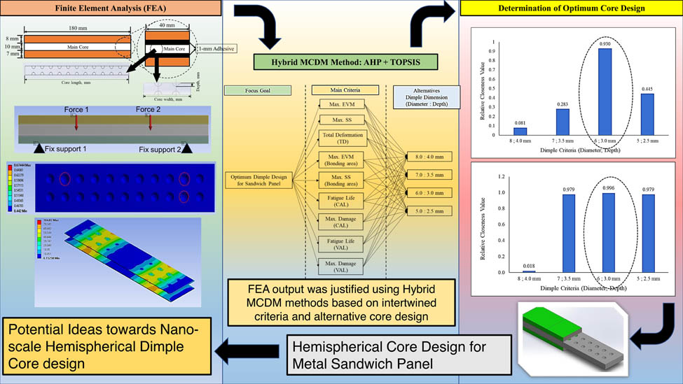
The aim of this article is to determine the relationships between the essential criteria for the performance of sandwich panels and various alternative hemispherical core designs using a hybridisation technique within the multi-criteria decision-making method. A major reduction in core density reduced the structural integrity of the metal sandwich panel and promoted a significant effect of failure such as early delamination. Therefore, an effective optimisation analysis with highly precise determination is required to reduce the overall cost. The output from the finite element analysis was segregated into the nine main criteria that contributed to the sandwich panel performance. The analytical hierarchical process was used to develop a pairwise comparison matrix table and determine the weightages for each criterion. Further analysis using the technique for order preference by similarity to ideal solution (TOPSIS) was conducted to find the optimal solution for the core design. The results showed that a hemispherical dimple core design with a diameter of 6.0 mm and a depth of 3.0 mm achieved the highest-ranked closeness coefficient (CCi = 0.930 and 0.996) at both 70 and 50% of cyclic loading conditions. It was concluded that using small dimensions in the hemispherical core design configuration tends to produce better bonding strength performance in the sandwich panel, rather than configurations of larger dimensions. Hence, this method proved to be effective in determining the optimum selection, although the criteria and alternatives are intertwined, which complicates the process.
Graphical abstract
1 Introduction
A sandwich panel consists of two or more panels of either similar or dissimilar materials, which are bonded together using various methods such as adhesive joints, stitching, welding or fastening, so it performs as a single sandwich panel under various loading conditions [1,2,3]. The literature indicates that the application of sandwich panels is useful in reducing the panel weight and improving mechanical properties such as the panel strength and energy absorption [4,5,6]. However, under extreme conditions – such as constant loading, variable loading or high-velocity impact – sandwich panels are prone to experience failures such as debonding or delamination at the bonding layer of the panel. Metal sandwich panels such as foam, honeycomb and lattice panels have open or closed cavities on their body structure [7,8,9]. These cavities are high to contribute to a catastrophic failure of the sandwich panel under extreme loading conditions. Therefore, it is vital to perform certain modifications to the core panel of the sandwich panel, either to the core surface and/or to the core material properties in order to maintain its structural integrity, but without significantly reducing the core density [9,10]. This proposed design modification involves many core design parameters and may require a highly time-consuming process. Therefore, it would be useful to perform an extended analysis using significant design parameters as part of an analytical approach to reducing the duration of the process, especially when many criteria and alternatives are involved in the design [11,12,13].
The multi-criteria decision-making (MCDM) method is a useful decision-making tool involving qualitative and quantitative factors [14,15]. The literature shows that the MCDM method has been suggested as a means to solve numerous engineering problems involving many design criteria and alternatives [16,17]. The most recent MCDM techniques are the analytical hierarchical process (AHP) and the technique for order preference by similarity to ideal solution (TOPSIS). These have been used due to their simplicity and adaptability to many engineering problems that require finding the optimal solution from various design parameters [18,19]. Although the AHP is said to have been largely influenced by expert opinion, in this study, it is compared with the finite element analysis (FEA) results and through consistency checking, which must be less than 0.1 to minimise bias and avoid any inconsistency. In addition, to enhance the accuracy of the findings, the AHP results are combined with those of the TOPSIS analysis to develop a more effective evaluation process and derive the optimum and ideal solution to the design problem [20]. Thus, through this hybrid technique, all the significant criteria for each alternative were assessed equally and represented in terms of rank. The highest-ranked, which was close to 1.0, was declared to be the best (i.e., optimal) solution to the engineering problem and was thus selected as the preferred design solution [21]. Therefore, the core design parameters, the results for which had been determined previously using the FEA, were used in the hybrid MCDM analysis to enhance the FEA results and obtain highly accurate results in order to determine the optimum hemispherical core design for sandwich panel applications.
The importance of determining the optimum hemispherical core design is vital for improving the failure behaviour of metal sandwich panels. The combination of the FEA results and the MCDM method provided a better approach to determining the optimum design for a core panel without involving additional costs in terms of the manufacturing process and the time taken [22]. Using FEA, the critical parameters that can contribute to the catastrophic failure of a metal sandwich panel – such as delamination, tearing and buckling – can be determined based on the localised stress distribution and on fatigue analysis using stress life theory at the critical region of the sandwich panel [23,24]. To further analyse core design optimisation, it is useful to employ the hybrid analysis using the AHP and the TOPSIS since this can analyse and reveal all the intertwined dependent factors [25,26]. From the previous literature, it was noted that the MCDM method is usually used in engineering design selection, accompanied by survey and questionnaire forms [27]. There is a lack of research that analyses in-depth the critical factors that contribute to metal sandwich panel failure using the hybrid MCDM analysis method to determine the optimum sandwich panel core design [28,29]. This study gap made it vital to explore this topic to improve the manufacturing process and knowledge of the failure behaviour of metal sandwich panels. Hence, the proposed method could be a milestone in the metal sandwich panel field, especially when designing and choosing the best core configurations for a metal sandwich panel.
In this study, the results of the FEA under four-point bending conditions were segregated into nine main criteria that make major contributions to the sandwich panel’s performance. The objectives of this study are to investigate the optimum solution for a hemispherical dimple core design through an analytical approach using the MCDM method, the AHP, and the TOPSIS. The AHP was used to determine the weightages for all nine main criteria that had been segregated through the FEA results. The analysis was extended using the TOPSIS to determine the best alternative core design for a sandwich panel. This study contributes in three key ways to the literature on the selection of the optimum core design for a sandwich panel and the method described. First, it outlines the relationship between the significant criteria for the core design parameters, along with all the alternatives analysed together, to produce an optimum solution to the problems of the core design. Second, it reveals the potential of the FEA results to be infused with the hybridisation MCDM method to enhance the accuracy with which engineering design problems are solved and reduce the time required to solve a design problem. Finally, it provides the simplest method for selecting the core design for a sandwich panel without involving the more complex design approaches to solving such problems. This combined method can be used in future core design selection, especially in nano-scale designs and complex and tiny metal sandwich panel applications.
2 Materials and methods
In this study, a geometrical sandwich panel was developed using a finite element modelling software package and was simulated under four-point bending conditions. The geometrical sandwich panel consisted of AR500 steel as the top and bottom panels with the magnesium alloy AZ31B as the main core panel. The main core panel surface was modified with different sizes of hemispherical dimple core designs. The hemispherical dimples were 5.0, 6.0, 7.0 and 8.0 mm in diameter and 2.5, 3.0, 3.5 and 4.0 mm deep. The methodology for this study is presented in the flowchart shown in Figure 1. The input from the FEA was then analysed and optimised using hybrid MCDM tools to select the optimum hemispherical core design to use as the main core for a metallic sandwich panel.
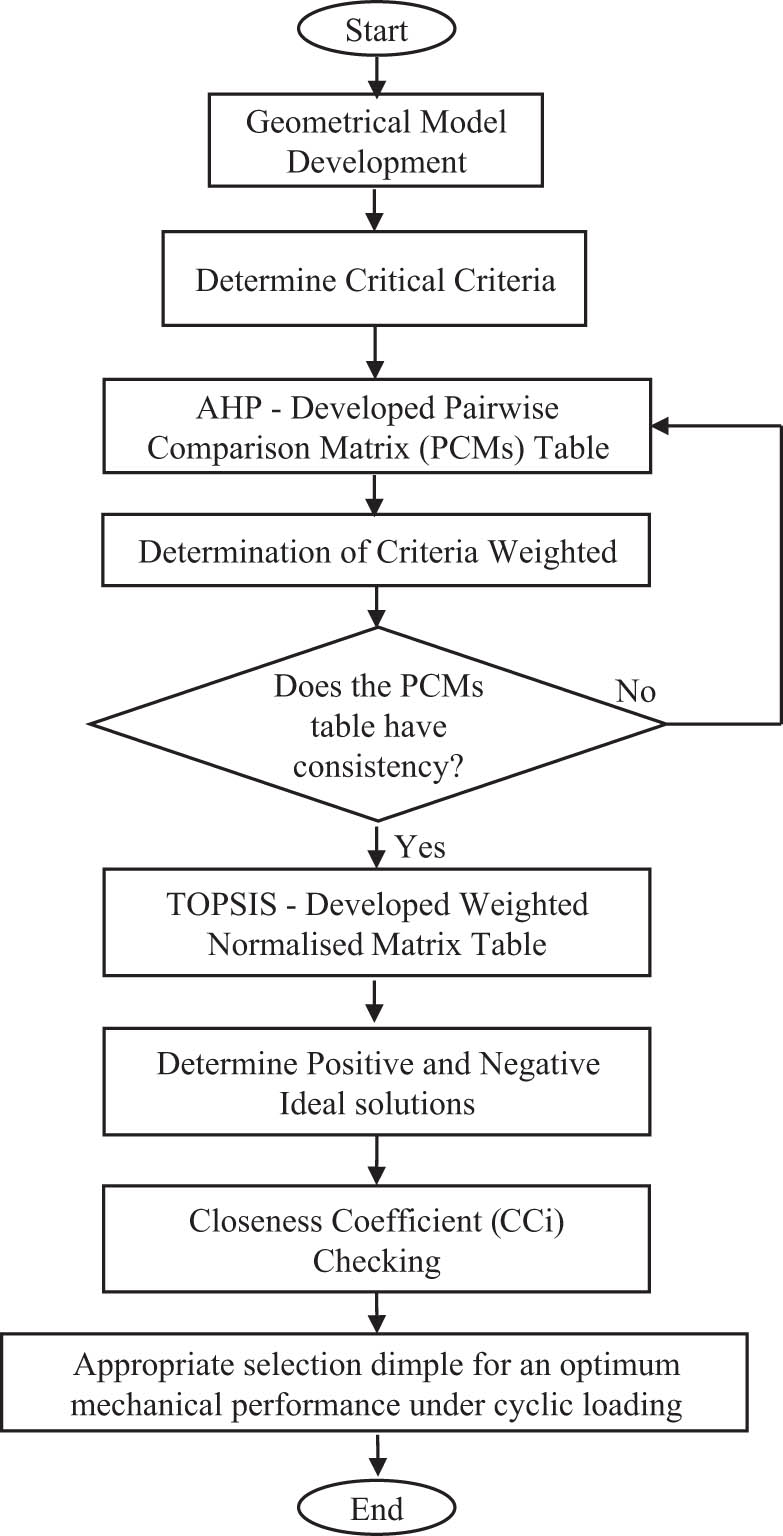
The methodology flowchart for this study.
2.1 Classification of criteria from FEA
A three-dimensional geometrical sandwich panel was simulated using four-point bending under constant amplitude loading (CAL) and variable amplitude loading (VAL), based on ASTM C393 [30]. The geometrical sandwich panel was 180 mm in length, 40 mm in width and 27 mm thick, including the adhesive material, as shown in Figure 2. Epoxy resin was assigned as the adhesive material to bond the sandwich panel, which was modelled with a 1.0 mm thickness at the upper and lower bonding regions in the simulation. A four-point bending setup was preferable in the simulation since this provided an equal loading distribution across the sandwich panel in more optimum conditions than the three-point bending setup [31]. This was important in indicating the delamination phenomena that occurred, especially at the bonding layer of the sandwich panel. The Gerber fatigue stress life theory has been used to simulate sandwich panels at their maximum potential performance since it is the most suitable to use with highly ductile materials and only considers the maximum fatigue failure of the materials [32]. A tetrahedral mesh type with a fine span angle centre was used, while a meshing size of 1.0 mm was chosen as this would produce highly accurate and precise simulations. For the hemispherical dimple core sandwich panel with a diameter of 5.0 mm, the total number of nodes was 1,482,584, with 753,732 elements. For the hemispherical dimple core sandwich panel with a diameter of 6.0 mm, the total number of nodes was 1,491,058, with 756,443 elements. For the hemispherical dimple core sandwich panel with a diameter of 7.0 mm, the total number of nodes was 1,497,846, with 758,222 elements. For the hemispherical dimple core sandwich panel with a diameter of 8.0 mm, the total number of nodes is 1,507,227, with 760,999 elements. In terms of loading, the geometrical sandwich panel was subjected to 70 and 50% of the maximum loading strength of the weakest material in the sandwich panel, magnesium alloy AZ31B. This was to ensure that the loading given to the sandwich panel did not exceed the maximum capacity of the metal sandwich panel and to maintain the structural integrity of the sandwich panel bonding area. In addition, the selection of 70 and 50% of the maximum loading strength was made to highlight the differences in mechanical performance, especially when using the MCDM method, the AHP, and the TOPSIS to determine the optimum dimple core design. The aim was to ensure that at the next analysis stage (using the AHP and the TOPSIS), the final analysis outcomes would prove consistent and enhance the accuracy of the results. The responses from this analysis were categorised into the nine main criteria that made the principal contributions to the sandwich panel failure, as shown in Table 1. Figures 3 and 4 illustrate the example data. The von Mises stress and shear stress distributions on the geometrical sandwich panel were gathered from the FEA as two of the sets of criteria analysed in this study.
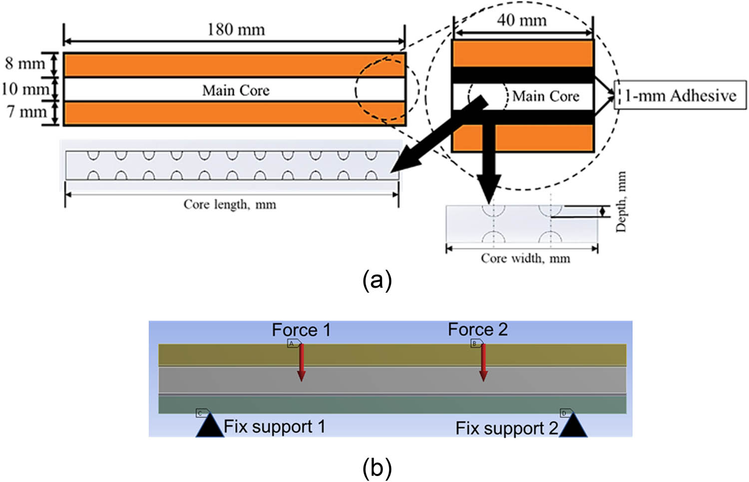
The geometrical sandwich panel with its (a) size and dimension and (b) in simulation.
The segregated main criteria after being segregated from the FEA results
| The main criteria | |
|---|---|
| 1 | Max. von Mises stress (MPa) |
| 2 | Max. shear stress (MPa) |
| 3 | Total deformation (mm) |
| 4 | Max. von Mises stress on bonding area (MPa) |
| 5 | Max. Shear stress on bonding area (MPa) |
| 6 | Fatigue life at core panel (CAL) |
| 7 | Max. damage value at core panel (CAL) |
| 8 | Fatigue life at core panel (VAL) |
| 9 | Max. damage value at core panel (VAL) |
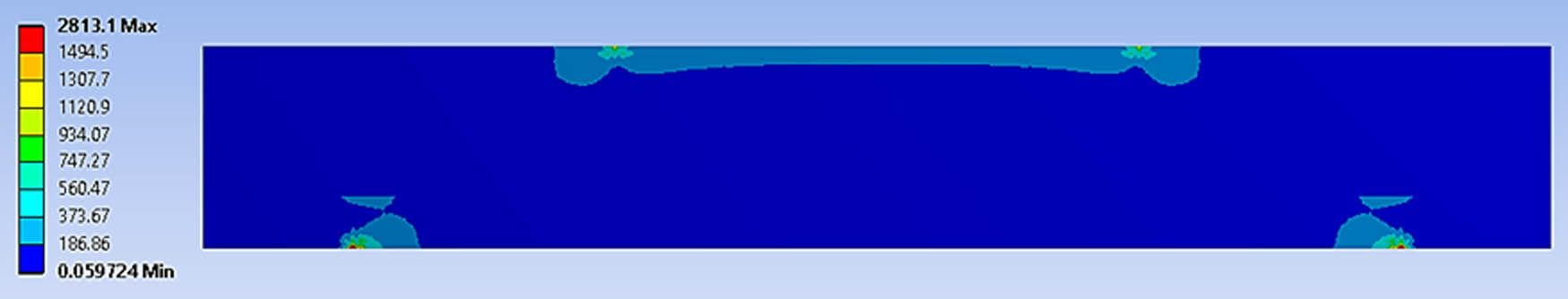
The example of the von Mises stress distribution for the geometrical sandwich panel using a four-point bending simulation under 70% of cyclic loading conditions.
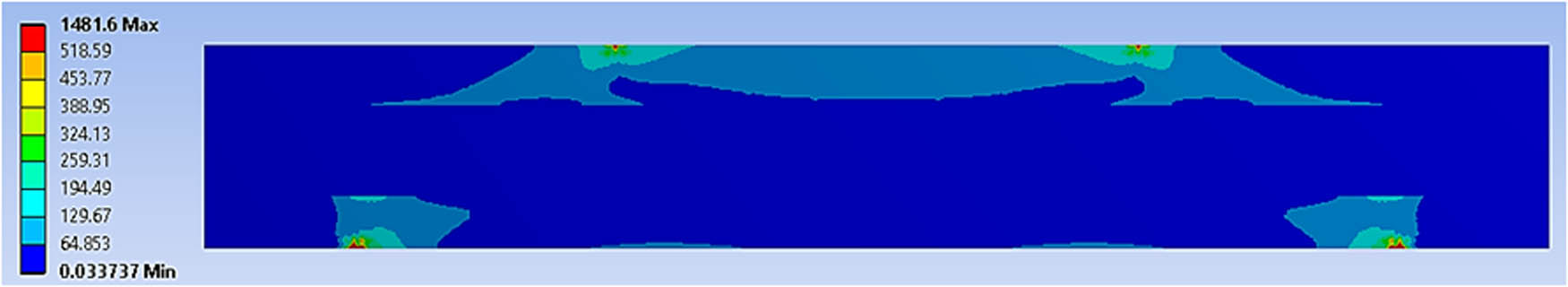
The example of the shear stress distribution for the geometrical sandwich panel using a four-point bending simulation under 70% of cyclic loading conditions.
These nine main criteria were selected from the FEA due to their significant effects on the overall sandwich panel performance. According to the existing literature, delamination effects under four-point bending conditions occur when the effective bonding area experiences a high stress concentration at the bonded area due to the continuous loading given to the panel before it fails [33,34]. This continuous loading leads to multiple failure effects, such as matrix cracking, face wrinkling and shear yielding, which are the main contributory factors to the significant delamination phenomena that affect the sandwich panel [13,35]. Moreover, the stress distribution under continuous cyclic loading in four-point bending conditions also determined the fatigue life and damage distribution of the sandwich panel, which could vary based on the cyclic loads given to the panel. Therefore, based on that explanation, it can be deduced that it is worth exploring the performance of non-homogenous materials in sandwich panels with different hemispherical dimple core designs, especially in the bonding area. It is also vital to determine their performance due to their significant effects on the delamination phenomena and to improve the interlaminar bonding strength of the panel [4,33,36]. However, determining their performance based on the FEA results has not provided viable results due to the various criteria that need to be considered. Therefore, MCDM tools like the AHP and the TOPSIS are useful to explore, besides the genetic algorithm and the more economical tools that are used, in order to enhance the results gathered from the FEA and determine the optimum core design of a metal sandwich panel [13,28,37].
2.2 Defining the main criteria weightages using the AHP
In defining the weightages for each criterion identified from the FEA, the AHP was used to perform and construct a fair pairwise comparison matrix (PCM) table. The PCM table was constructed based on the hierarchical tree, which consists of the main goal and the nine main criteria, along with the four hemispherical core design alternatives, as shown in Figure 5. The Saaty rating scale was referred to when constructing the fair PCM table, with a geometric mean technique used to aggregate the responses for the main criteria, as shown in Table 2.
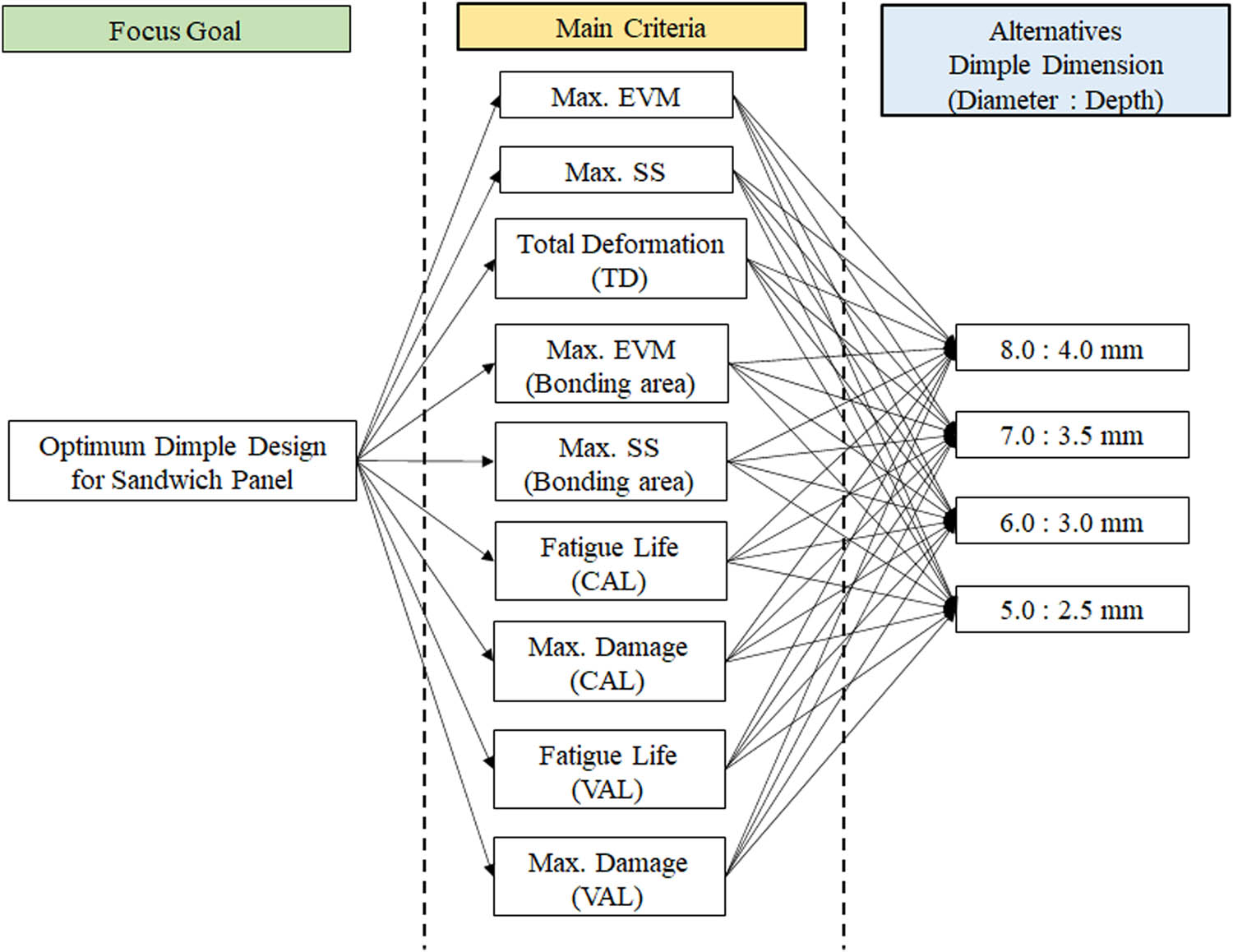
The constructed hierarchical tree based on the FEA results.
The Saaty rating scale for constructing the PCM table [42]
| Values | Value definition |
|---|---|
| 1 | Both elements are equal |
| 3 | Moderate importance |
| 5 | Strong importance |
| 7 | Very strong importance |
| 9 | Extreme importance |
| 2, 4, 6, 8 | Intermediate values |
In addition, all the responses in the PCM table assigned to these nine main criteria were evaluated carefully, based on previous research by several authors [36,38,39]. To avoid bias and ensure the consistency of the values in the PCM table, final tests were undertaken by conducting consistency checks using the consistency index (CI) shown in Eq. (1) and the consistency ratio (CR) shown in Eq. (2) [40]:
Eq. (2) was divided by the random consistency index (RI) value as shown in Table 3.
This was important for improving the balance and consistency between each value assigned in the PCM table and enhancing the reliability of the value assigned [25,37,41]. The main steps for determining the weightages for each criterion are illustrated in Figure 6. The determined weights that had been assigned using the AHP were then used as the weightages for each criterion in the following analysis, which used the TOPSIS.
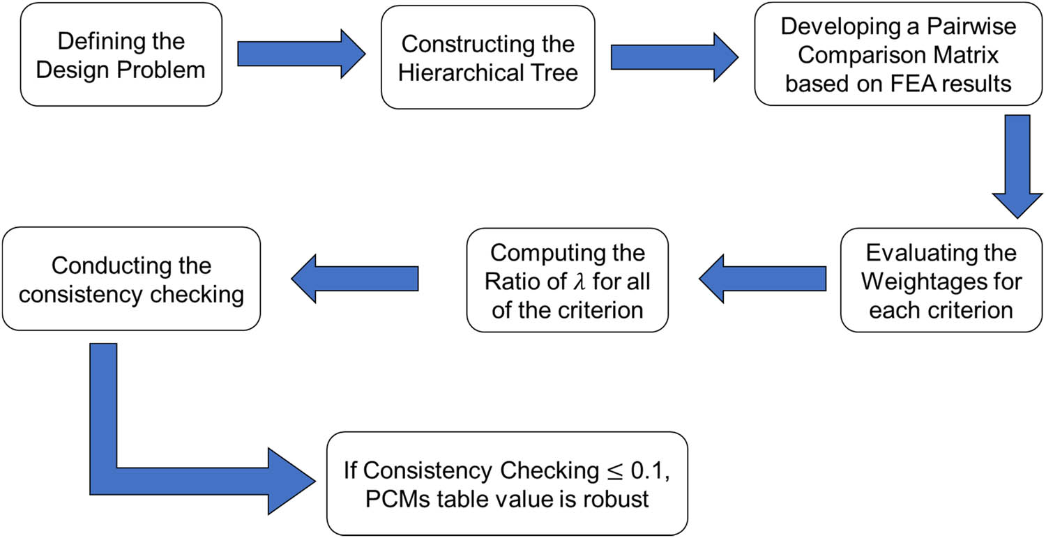
The steps to consider when determining the weightages for each criterion.
2.3 Determining the optimum hemispherical core design for a sandwich panel using the TOPSIS
In the next analysis, the optimum hemispherical core design of a sandwich panel was determined by analysing the weightages for each criterion using the normalised decision matrix (DM) table and the TOPSIS method. The TOPSIS method utilises the concept of shortest and farthest distances through the ideal positive-negative solution [28,29]. The normalised DM table was constructed using Eq. (3) [19,26]:
The normalised DM table values were then multiplied by the weightages for each criterion to produce the weighted normalised DM table. Once this table had been established, the positive- and negative-ideal solutions were determined. At this stage, the positive- and negative-ideal solutions for the criteria values in the weighted normalised DM table were determined, based on the shortest and farthest distance values for each criterion. The farthest distance value becomes the positive-ideal solution, while the shortest distance value becomes the negative-ideal solution [19,22,27]. However, this study identified that some criteria, such as total deformation and the maximum damage value on the core panel, tended to have the shortest distance values and thus became positive-ideal solutions. This was because the minimised value of the ideal solution was more favourable and had a more significant effect on the performance of the sandwich panel than the maximised value of the ideal solution. Through these positive–negative values of the ideal solutions for the main criteria, the separation measure for each alternative (in this case, the different hemispherical core designs) was conducted using Eqs. (4) and (5) [19,21,28]:
Once the positive and negative separation measures had been evaluated, the final analysis of relative closeness to the ideal solution was conducted using equation (6) [21,28]:
In the relative closeness analysis, any value close to a value of 1.0 becomes the most favourable alternative within the analysis and is usually ranked the highest [19,43]. A set of alternatives was ranked according to an order range of between 0 < Ci < 1. Any value close to a value of 0.0 is usually less favourable within the analysis. Therefore, the output from the FEA and the subsequent analysis stages using the hybrid technique of the AHP and the TOPSIS enabled the optimum hemispherical sandwich panel core design to be determined and justified.
2.4 Experimental work for the validation process
For the experimental work, the material for the top and bottom sheets was AR500 steel, while the core material was magnesium alloy AZ31B. All the materials had been cut using a computer numerical control machine and sandwiched together using ET538 epoxy resin from Permabond. All the specimens had been cured for 3 days at room temperature, as shown in Figure 7. The metal sandwich panel specimens were tested using the 100kN Fatigue Servo Hydraulic Machine, as shown in Figure 8. The strain gauge was set up at the bonding area of the metal sandwich panel specimens, as shown in Figure 9.
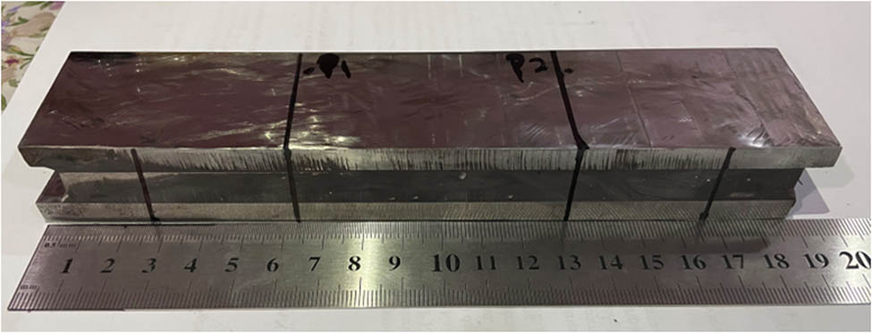
A metal sandwich panel specimen after being cured for 3 days at room temperature.
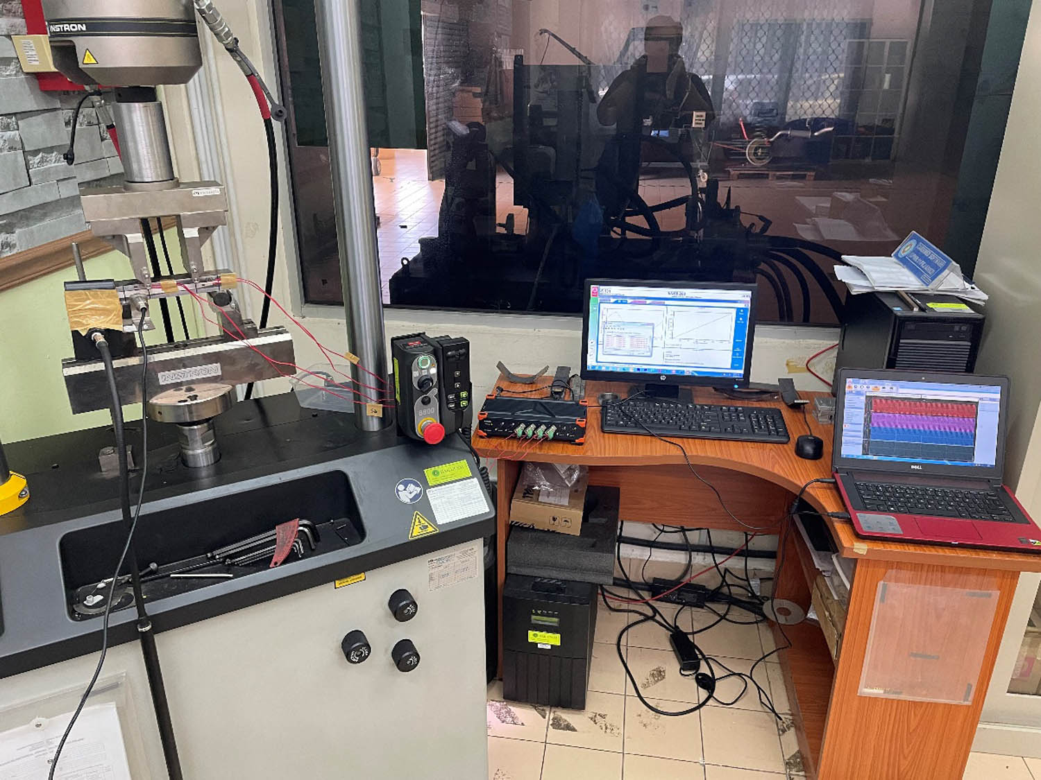
The set-up of the four-point bending test using Fatigue Servo Hydraulic Machine and a Dewesoft Data Acquisition system.
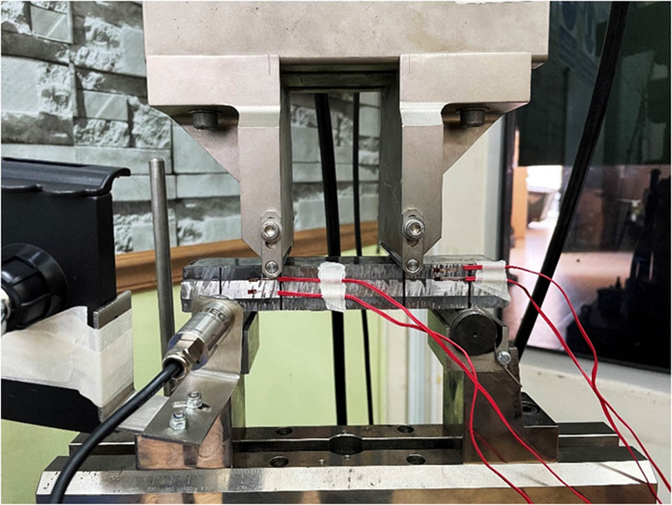
The metal sandwich panel specimen in the four-point bending setup with the strain gauge at the bonding area of the metal sandwich panel attached to the data acquisition system.
The Dewesoft data acquisition system was used to capture the strain signals at the bonding area while cyclic loading was given to the sandwich panel. A four-point bending setup was chosen since this produced an equivalent force that would be distributed on the metal sandwich panel so that an optimum force was given to the sandwich panel. Two hemispherical dimple core designs – with diameters of 8.0 and 6.0 mm and depths of 4.0 and 3.0 mm – were tested at 70 and 50% of the maximum strength of the metal sandwich panel under constant cyclic loading. The failure of the sandwich panel was observed, the indication for which was based on significant effects such as the peak data strain signal, random friction sounds and debonding at the bonding layer of the sandwich panel.
3 Results and discussion
3.1 FEA of the sandwich panel under four-point bending conditions
The FEA of the geometrical metal sandwich panel was conducted using four-point bending simulations under CAL and VAL. Four types of geometrical sandwich panels were used; these featured different hemispherical core designs in terms of their diameter and depth. This study focused on the effects of different sizes and dimensions of hemispherical core design, which would indicate the factors that significantly affected the sandwich panel’s performance. These involved the stress distribution on the whole panel and at the bonding area, total deformation, fatigue life distribution before failure and maximum damage distribution in the core panel. Figures 10–14 show the FEA results following the four-point bending simulation. The figures reveal that significant stress distribution and total deformation occurred in the bonding region and the core panel, which were essential criteria and needed to be considered in the subsequent analysis. The final FEA results were categorised, as presented in Table 5. The results demonstrate that nine main criteria significantly affected the performance of the sandwich panel and were the main contributors to its failure.
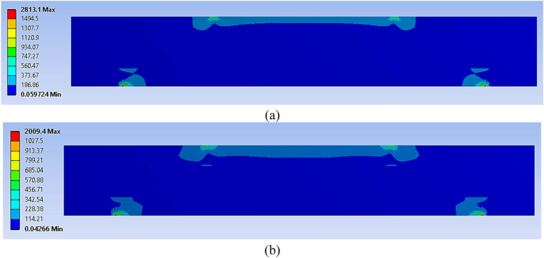
Von Mises stress distribution in the geometrical sandwich panel at (a) 70% and (b) 50% of cyclic loading conditions.
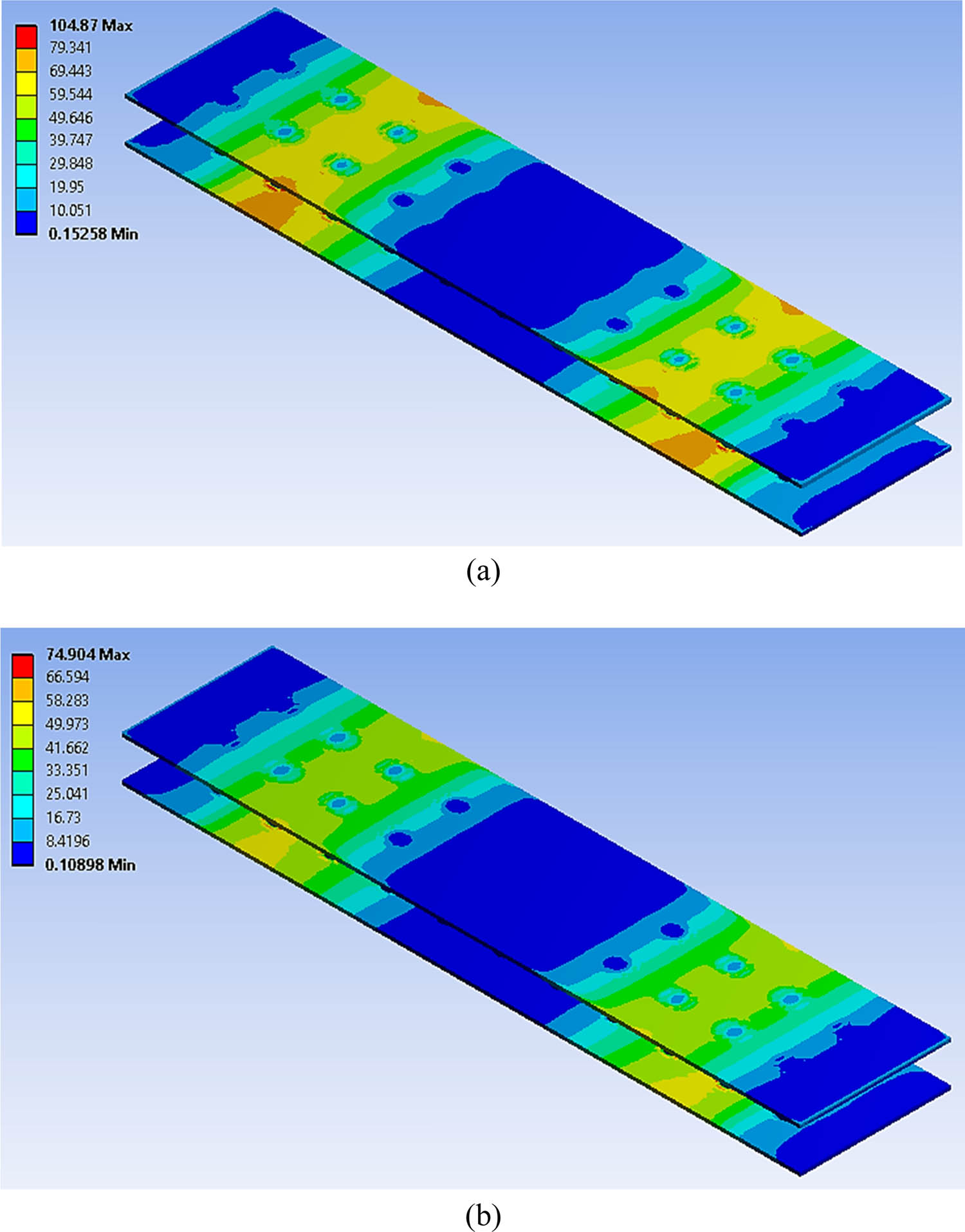
Von Mises stress distribution in the bonding area of the geometrical sandwich panel at (a) 70% and (b) 50% of cyclic loading conditions.
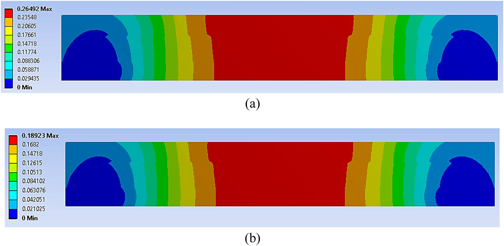
The total deformation experienced by the geometrical sandwich panel at (a) 70% and (b) 50% of cyclic loading conditions.
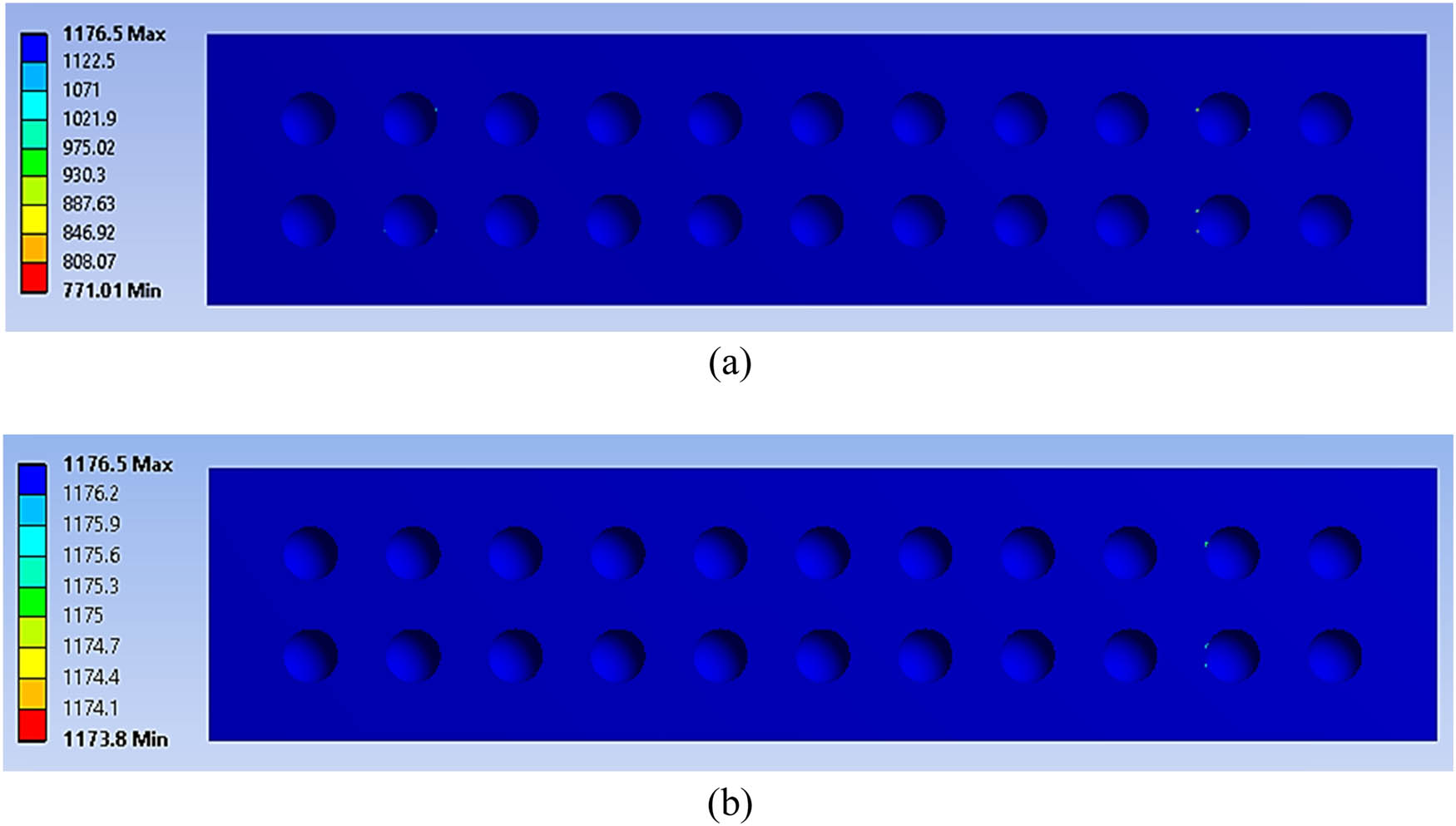
The fatigue life distribution before failure for the geometrical sandwich panel at the core panel under (a) 70% and (b) 50% of cyclic loading conditions.
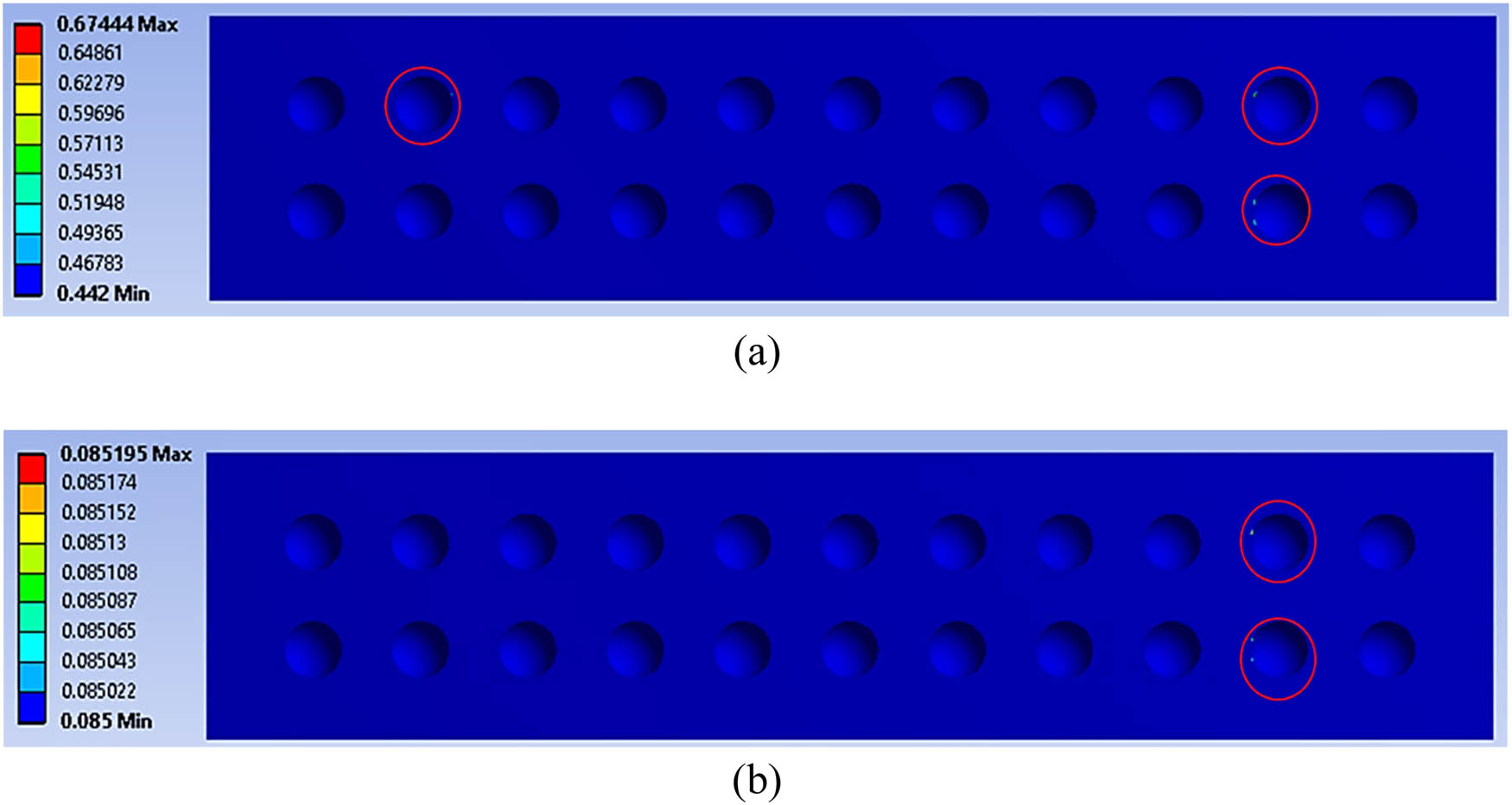
Damage distribution to the core panel at (a) 70% and (b) 50% of cyclic loading conditions (red circle indicates the maximum damage value at the core panel).
The simulation showed promising results in terms of displaying the sandwich panel’s behaviour under four-point bending conditions. However, deciding on the optimum core design for the sandwich panel remained difficult due to the data intertwined between the various criteria. As Tables 4 and 5 illustrate, the values for all nine main criteria were fairly close and intertwined. Therefore, further analysis was crucial to identify the interconnection between these nine main criteria from the FEA results, which had a close relationship with the overall performance of the geometrical metal sandwich panel in terms of stress distribution, bonding strength and fatigue life.
The segregated main criteria from the FEA results with the values of alternative hemispherical core designs at 70% of cyclic loading conditions
| Criteria | Alternatives (Diameter; Depth) | |||
|---|---|---|---|---|
| 8.0; 4.0 mm | 7.0; 3.5 mm | 6.0; 3.0 mm | 5.0; 2.5 mm | |
| Max. von Mises stress (MPa) | 2814.9 | 2808.2 | 2831.4 | 2798.9 |
| Max. shear stress (MPa) | 1483.2 | 1479.6 | 1494.5 | 1474.7 |
| Total deformation (mm) | 0.275 | 0.269 | 0.265 | 0.262 |
| Max. von Mises stress on bonding area (MPa) | 111.3 | 110.7 | 98.4 | 96.0 |
| Max. shear stress on bonding area (MPa) | 63.9 | 63.4 | 55.7 | 54.1 |
| Fatigue life at core panel (CAL) | 1310700 | 1635400 | 2000900 | 1992400 |
| Max. damage value at core panel (CAL) | 0.674 | 0.686 | 0.001 | 0.691 |
| Fatigue life at core panel (VAL) | 2640000 | 2830000 | 2990000 | 2990000 |
| Max. damage value at core panel (VAL) | 0.757 | 0.671 | 0.601 | 0.669 |
The segregated main criteria from the FEA results with the values of alternative hemispherical core designs at 50% of cyclic loading conditions
| Criteria | Alternatives (Diameter; Depth) | |||
|---|---|---|---|---|
| 8.0; 4.0 mm | 7.0; 3.5 mm | 6.0; 3.0 mm | 5.0; 2.5 mm | |
| Max. von Mises stress (MPa) | 2026.5 | 2016.2 | 2009.4 | 2003.6 |
| Max. shear stress (MPa) | 1066.8 | 1061.7 | 1058.3 | 1055.4 |
| Total deformation (mm) | 0.196 | 0.192 | 0.189 | 0.187 |
| Max. von Mises stress on bonding area (MPa) | 74.9 | 72.8 | 74.9 | 71.9 |
| Max. shear stress on bonding area (MPa) | 42.5 | 40.2 | 43.1 | 40.5 |
| Fatigue life at core panel (CAL) | 1995460 | 2000900 | 2000900 | 2000900 |
| Max. damage value at core panel (CAL) | 0.085 | 0.001 | 0.001 | 0.001 |
| Fatigue life at core panel (VAL) | 2991400 | 2992900 | 2993100 | 2993100 |
| Max. damage value at core panel (VAL) | 0.003 | 0.003 | 0.003 | 0.003 |
3.2 Determination of the weightages for failure criteria using the AHP
Using the categorised FEA results from Tables 4 and 5, as outlined in Section 3.1, the PCM table was developed to determine the weightages for each failure criterion. The PCM table enabled a comparison between the connections involving each criterion using the Saaty rating scale [27,39,42]. From the hierarchical tree, shown in Figure 5 in the previous section, the nine main criteria and their definitions were developed; these are shown in Table 6. Table 7 shows the constructed PCM table for all nine main criteria. The linguistic scale on the PCM table was determined using the Saaty rating scale, based on previous research conducted by various authors.
The nine main criteria with their definitions for the analysis using each weighted criterion
| Criteria | Criteria definitions |
|---|---|
| Max. von Mises stress (MPa) | The maximum strength of the sandwich panel can withstand before failure |
| Max. shear stress (MPa) | The maximum shear strength of the sandwich panel can withstand before debonding |
| Total deformation (mm) | The maximum elongation experienced by the sandwich panel when subjected to loading |
| Max. von Mises stress on bonding area (MPa) | The maximum strength at the bonding area of the sandwich panel can withstand before failure |
| Max. shear stress on bonding area (MPa) | The maximum shear strength at the bonding area of the sandwich panel can withstand before debonding |
| Fatigue life at core panel (CAL) | The amount of life possessed by the core panel of the sandwich panel under constant cyclic loading |
| Max. damage value at core panel (CAL) | The maximum damage value at the core panel area under constant cyclic loading |
| Fatigue life at core panel (VAL) | The amount of life possessed by the core panel of the sandwich panel under variable cyclic loading |
| Max. damage value at core panel (VAL) | The maximum damage value at the core panel area under variable cyclic loading |
The PCM table, developed according to the Saaty rating scale for the nine main criteria
| Criteria | C1 | C2 | C3 | C4 | C5 | C6 | C7 | C8 | C9 |
|---|---|---|---|---|---|---|---|---|---|
| Max. von Mises stress (MPa)–C1 | 1.00 | 3.00 | 3.00 | 3.00 | 2.00 | 0.20 | 0.33 | 0.20 | 0.33 |
| Max. shear stress (MPa)–C2 | 0.33 | 1.00 | 3.00 | 3.00 | 2.00 | 0.20 | 0.33 | 0.20 | 0.33 |
| Total deformation (mm)–C3 | 0.33 | 0.33 | 1.00 | 0.33 | 0.33 | 0.33 | 0.33 | 0.33 | 0.33 |
| Max. von Mises stress on bonding area (MPa)–C4 | 0.33 | 0.33 | 3.00 | 1.00 | 2.00 | 0.33 | 0.50 | 0.33 | 0.50 |
| Max. shear stress on bonding area (MPa)–C5 | 0.50 | 0.50 | 4.00 | 0.50 | 1.00 | 0.33 | 0.50 | 0.33 | 0.50 |
| Fatigue life at core panel (CAL)–C6 | 5.00 | 5.00 | 4.00 | 3.00 | 3.00 | 1.00 | 4.00 | 0.50 | 2.00 |
| Max. damage value at core panel (CAL)–C7 | 3.00 | 3.00 | 3.00 | 2.00 | 2.00 | 0.33 | 1.00 | 0.20 | 0.50 |
| Fatigue life at core panel (VAL)–C8 | 5.00 | 5.00 | 4.00 | 3.00 | 3.00 | 2.00 | 5.00 | 1.00 | 3.00 |
| Max. damage value at core panel (VAL)–C9 | 3.00 | 3.00 | 3.00 | 2.00 | 2.00 | 0.50 | 2.00 | 0.33 | 1.00 |
To avoid any perception of bias and ensure the reliability of the PCM table for this study, consistency checking was undertaken on the criteria values in the PCM table. Table 8 shows the average λ value that was calculated from the ratio of the weighted summation value for each criterion to the normalised value for each criterion in the PCM table. Therefore, Eq. (1) was used to determine the CI for the developed PCM table, which was found to be 0.13871. Then, Eq. (2) was used to determine the CR, after which it was found that the CR value was 0.096, which is less than 0.1. The CR value was less than 0.1, so it could be concluded that the constructed PCM table was acceptable from a consistency perspective and free from any perceptions of bias. Thus, all the weighted criteria values in the PCM table could be used to perform the subsequent analysis, which would determine the optimum hemispherical core design for sandwich panel applications.
Summarisation of the weighted analysis for all the criteria
| Criteria | Weighted sum value known as λ for each criterion | Weightage of each criterion | Ratio of λ to weightage for each criterion | Ratio index (n) | CR |
|---|---|---|---|---|---|
| Max. EVM (MPa) | 0.80 | 0.08 | 10.60 | − | |
| Max. SS (MPa) | 0.63 | 0.06 | 10.67 | 0 | |
| TD (mm) | 0.31 | 0.03 | 10.19 | 0.58 | |
| Max. EVM on bonding area (MPa) | 0.58 | 0.06 | 10.26 | 0.90 |
|
| Max. SS on bonding area (MPa) | 0.55 | 0.05 | 10.03 | 1.12 | CI = (10.11 − 9)/(9 − 1) = 0.139 |
| Fatigue life at core panel (CAL) | 2.14 | 0.22 | 9.76 | 1.24 | Using the CI value, the CR were determined: |
| Max damage value on core (CAL) | 0.99 | 0.10 | 10.05 | 1.32 |
|
| Fatigue life at core panel (VAL) | 2.73 | 0.27 | 9.94 | 1.41 | CR = (0.139)/1.45 = 0.096 |
| Max damage value on core (VAL) | 1.25 | 0.13 | 9.48 | 1.45 | |
| Average λ Max | 10.11 | CR < 0.1; Acceptable |
3.3 Determining the optimum hemispherical core design using the TOPSIS
As this study employed the hybridisation technique of MCDM, the weightages for each criterion were determined using the AHP method and processed using the TOPSIS method. This would resolve the differences between the several hemispherical core design alternatives and thus ascertain the optimum design for use in sandwich panel applications. To determine the optimum hemispherical core design, a normalised DM table was constructed. Using Eq. (3), the weightages for each criterion were multiplied by the normalised DM table values to obtain the weighted normalised DM table, as shown in Tables 9 and 10.
The weighted normalised DM table at 70% of cyclic loading conditions
| Criteria | Alternatives (Diameter; Depth) | |||
|---|---|---|---|---|
| 8.0; 4.0 mm | 7.0; 3.5 mm | 6.0; 3.0 mm | 5.0; 2.5 mm | |
| Max. von Mises stress (MPa) | 0.038 | 0.038 | 0.038 | 0.037 |
| Max. shear stress (MPa) | 0.030 | 0.029 | 0.030 | 0.029 |
| Total deformation (mm) | 0.015 | 0.015 | 0.017 | 0.014 |
| Max. von Mises stress on bonding area (MPa) | 0.030 | 0.030 | 0.027 | 0.026 |
| Max. shear stress on bonding area (MPa) | 0.030 | 0.029 | 0.026 | 0.025 |
| Fatigue life at core panel (CAL) | 0.082 | 0.102 | 0.125 | 0.124 |
| Max. damage value at core panel (CAL) | 0.056 | 0.057 | 0.000 | 0.058 |
| Fatigue life at core panel (VAL) | 0.126 | 0.135 | 0.143 | 0.143 |
| Max. damage value at core panel (VAL) | 0.074 | 0.065 | 0.058 | 0.065 |
The weighted normalised DM table at 50% of cyclic loading conditions
| Criteria | Alternatives (Diameter; Depth) | |||
|---|---|---|---|---|
| 8.0; 4.0 mm | 7.0; 3.5 mm | 6.0; 3.0 mm | 5.0; 2.5 mm | |
| Max. von Mises stress (MPa) | 0.038 | 0.038 | 0.038 | 0.037 |
| Max. shear stress (MPa) | 0.030 | 0.030 | 0.029 | 0.029 |
| Total deformation (mm) | 0.015 | 0.015 | 0.015 | 0.015 |
| Max. von Mises stress on bonding area (MPa) | 0.029 | 0.028 | 0.029 | 0.028 |
| Max. shear stress on bonding area (MPa) | 0.028 | 0.027 | 0.028 | 0.027 |
| Fatigue life at core panel (CAL) | 0.109 | 0.110 | 0.110 | 0.110 |
| Max. damage value at core panel (CAL) | 0.099 | 0.001 | 0.001 | 0.001 |
| Fatigue life at core panel (VAL) | 0.137 | 0.137 | 0.137 | 0.137 |
| Max. damage value at core panel (VAL) | 0.066 | 0.066 | 0.066 | 0.066 |
Through the information in Tables 9 and 10, the positive- and negative-ideal solutions for each criterion were determined. Table 11 shows the positive- and negative-ideal solutions that were segregated from the information in Tables 9 and 10. As Table 11 shows, some of the features, such as the total deformation and maximum damage value of the core panel under CAL and VAL conditions, were the preferred choices because the minimum values of these properties were preferable due to their minimal impact on the performance of the sandwich panel. For example, the minimal changes in total deformation of the sandwich panel under cyclic loading conditions were preferable to the extensive total deformation experienced by the sandwich panel. In previous literature, it has also been highlighted that the value of the positive-ideal solution was determined by the preferable solution value, while the negative-ideal solution was chosen from the least preferable solution value [22,28,43].
The positive- and negative-ideal solutions for each criterion
| Criteria | Si+ | Si− |
|---|---|---|
| Max. von Mises stress (MPa) | 0.038 | 0.037 |
| Max. shear stress (MPa) | 0.030 | 0.029 |
| Total deformation (mm) | 0.014 | 0.017 |
| Max. von Mises stress on bonding area (MPa) | 0.030 | 0.026 |
| Max. shear stress on bonding area (MPa) | 0.030 | 0.025 |
| Fatigue life at core panel (CAL) | 0.125 | 0.082 |
| Max. damage value at core panel (CAL) | 0.000 | 0.058 |
| Fatigue life at core panel (VAL) | 0.143 | 0.126 |
| Max. damage value at core panel (VAL) | 0.058 | 0.074 |
From the information in Table 11 and by using Eqs. (4) and (5), a summation of the positive- and negative-ideal solutions from all the criteria employed was determined for each alternative, as shown in Table 12. Therefore, as the positive- and negative-ideal solutions had been determined, the relative closeness value of each alternative was evaluated using Eq. (6). Relative closeness value analysis, also known as the closeness coefficient (CCi), was important in determining the ranking of all the alternatives in this study, as the TOPSIS method was based on the Euclidean distance between the closest and farthest distances of the positive- and negative-ideal solutions [21,28,39]. Finally, the alternative with a CCi value nearest to 1.0 was marked as the best alternative for the core design of a sandwich panel. It was found that the hemispherical dimple core design with a diameter of 6.0 mm and a depth of 3.0 mm ranked the highest and was therefore the preferred choice as the optimum core design for use in sandwich panel applications under 70 and 50% of cyclic loading conditions, as shown in Figures 15 and 16. Therefore, it was concluded that by extending the FEA using the hybrid MCDM method, the optimum core design for a sandwich panel could be determined. This was achieved at no additional cost, which was especially useful since numerous factors need to be considered when making critical material or design selections.
The summation of positive- and negative-ideal solutions, based on the core design alternatives using CCi analysis
| Conditions | Si+ | Si− | Closeness coefficient (CCi) | Ranking |
|---|---|---|---|---|
| Under 70% of cyclic loading condition | 0.074 | 0.007 | 0.081 | 4 |
| 0.062 | 0.025 | 0.283 | 3 | |
| 0.006 | 0.075 | 0.930 | 1* | |
| 0.058 | 0.047 | 0.445 | 2 | |
| Under 50% of cyclic loading condition | 0.098 | 0.002 | 0.018 | 4 |
| 0.002 | 0.098 | 0.979 | 3 | |
| 0.000 | 0.098 | 0.996 | 1* | |
| 0.002 | 0.098 | 0.979 | 2 |
*The highest ranked to be selected as the most suitable dimple core design for sandwich panel.
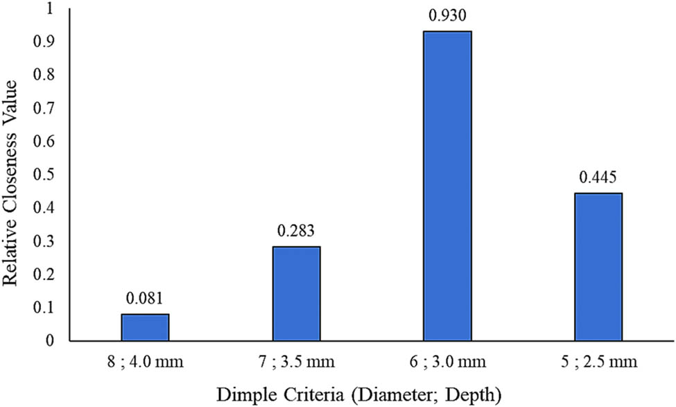
The ranking of the hemispherical dimple core design alternatives under 70% of cyclic loading conditions.
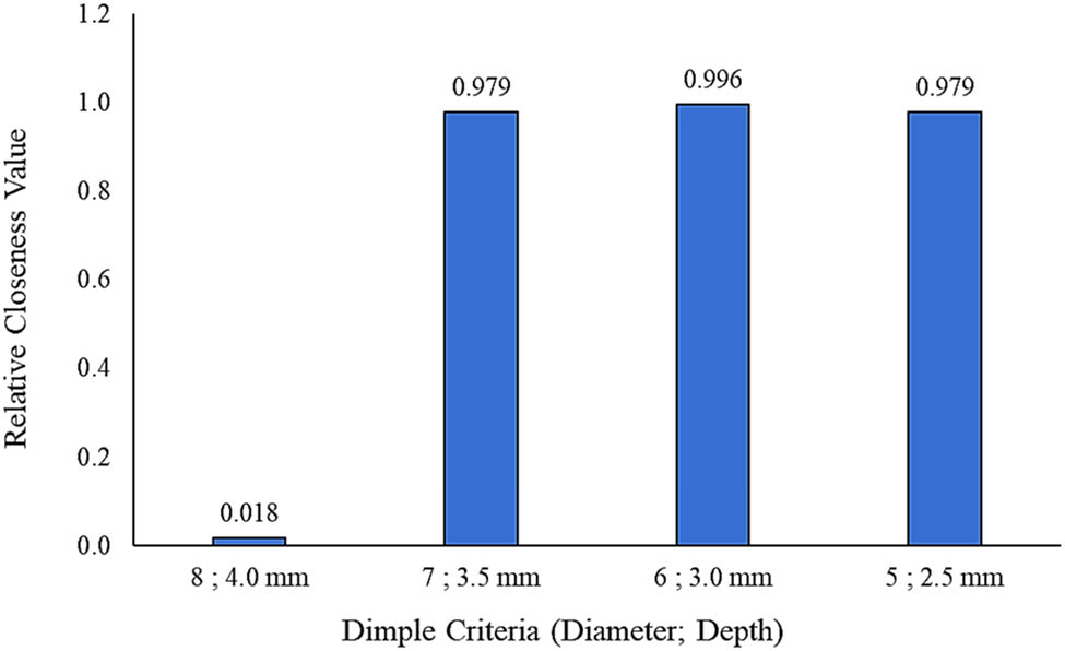
The ranking of the hemispherical dimple core design alternatives under 50% of cyclic loading conditions.
3.4 Validation of the MCDM method analysis
Based on the hybrid MCDM analysis using the AHP and TOPSIS methods, it was noted that the hemispherical dimple core design with a diameter of 6.0 mm and a depth of 3.0 mm showed positive results, so it was chosen as the optimum hemispherical dimple core design for metal sandwich panels. Figure 17 shows the fatigue life modelling for the hemispherical dimple core of the metal sandwich panel under constant and variable cyclic loading. The analysis was performed by assessing the maximum damage values at the critical dimple region on the core panel of the metal sandwich panel using specific finite element software. From these figures, comparisons were made between hemispherical dimples with diameters of 8.0 and 6.0 mm and depths of 4.0 and 3.0 mm. It was observed that the hemispherical dimples with diameters of 6.0 and 5.0 mm tended to have more life cycles under constant and variable cyclic loading compared to the others. This illustrates that hemispherical dimples with large dimensions in terms of diameter and depth tend to have lower life cycles and be more likely to experience early delamination phenomena when subjected to extreme loading conditions. In addition, the coefficient of determination showed that all the trendline values were above 0.85, proving the accuracy of the correlation between the maximum loading given to the metal sandwich panel and the total life cycles before failure, as well as a good level of agreement with the analysis of the hybrid MCDM method.
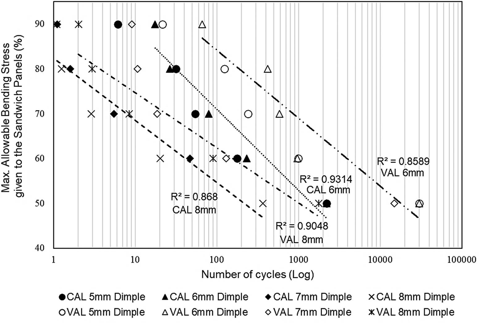
The fatigue life modelling between maximum allowable bending stress given to the metal sandwich panel against the total life cycles on logarithmic scale.
Furthermore, the bonding area of the metal sandwich panel was analysed using the experimental method of four-point bending under CAL conditions. Figure 18 shows the strain signal distribution at the bonding area of the metal sandwich panel using hemispherical dimples with a diameter of 6.0 mm and a depth of 3.0 mm. It can be observed that the strain signal showed a low noise distribution in a uniform trend and detected a high-frequency signal in the range of between 7,000 and 14,000 s. On the other hand, Figure 19 shows the strain signal distribution at the bonding area of the metal sandwich panel using hemispherical dimples with a diameter of 8.0 mm and a depth of 4.0 mm. It can be observed that the strain signal showed a high noise distribution in a non-uniform trend and detected a high-frequency signal at a range of between 1,500 and 2,700 s. Metal sandwich panel failure was also indicated based on the friction sound (at a high pitch) due to the matrix cracking at the dimple region. Therefore, Figures 18 and 19 indicate that a hemispherical dimple core with a diameter of 6.0 mm and a depth of 3.0 mm possessed higher life cycles under constant cyclic loading than the dimple core with a diameter of 8.0 mm and a depth of 4.0 mm. Thus, the above analysis proves the results produced through the MCDM analysis and indicates that the selection of hemispherical dimples with a diameter of 6.0 mm and a depth of 3.0 mm was accurate. It produced findings equivalent to the numerical (fatigue life modelling) and experimental results.
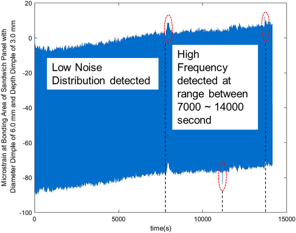
The microstrain signal at the bonding area of the metal sandwich panel using a hemispherical dimple core design with a diameter of 6.0 mm and a depth of 3.0 mm at 50% of maximum strength of cyclic loading.

The microstrain signal at the bonding area of the metal sandwich panel using a hemispherical dimple core design with a diameter of 8.0 mm and a depth of 4.0 mm at 50% of maximum strength of cyclic loading.
4 Conclusions
The aim of this study was to determine the optimum hemispherical dimple core design for metal sandwich panel applications that demonstrate improved failure behaviour. Nine main criteria were obtained from the FEA, and these were segregated and analysed using the hybrid MCDM method with the AHP and the TOPSIS. Using the AHP method, it was found that the CR for the developed PCM table was 0.09567. This consistency checking value was less than 0.1 (<0.1), which indicated that the PCM table values were acceptable from the perspectives of consistency and bias for all the selected criteria. The values in the PCM table were used to determine the weightages for all the essential criteria using both conditions (50 and 70% of cyclic loading). Using the TOPSIS, it was found that the highest-ranked alternative was the hemispherical dimple core design with a diameter of 6.0 mm and a depth of 3.0 mm under 70 and 50% of cyclic loading conditions (the CCi values were 0.9300 and 0.9956, respectively). The poorest behaviour was displayed by the hemispherical dimple core design of the largest size, which had a diameter of 8.0 mm and a depth of 4.0 mm (the CCi values were 0.0807 and 0.0182, respectively).
From this final analysis, it was concluded that using the smallest size and dimensions in the hemispherical dimple core design would tend to result in better performance in terms of bonding strength and fatigue life for sandwich panel applications. This illustrates that the optimisation process using the MCDM method produced a significant result, which was proven through the fatigue life modelling analysis at the dimple core hot region and the experimental method. It is therefore possible to determine the optimum hemispherical dimple core design for a non-homogenous metal sandwich panel at a low cost because this approach does not involve material or testing costs. It is recommended that this study should be extended by focusing on the development of nano-scale dimple core designs for applications that require lightness and greater complexity.
Acknowledgments
The authors would like to acknowledge the funding supported by Universiti Kebangsaan Malaysia (DIP-2019-015/GUP-2020-019/FRGS-1-2019-TK03-UKM-02-1) and also the facilities support provided by the Computational Laboratory at Universiti Pertahanan Nasional Malaysia.
-
Funding information: This research was funded by Universiti Kebangsaan Malaysia (DIP-2019-015, GUP-2020-019 and FRGS-1-2019-TK03-UKM-02-1).
-
Author contributions: The following contributions to this work were made by the following authors: conceptualisation: M.K.F., S.A., and M.F.A.; investigation: M.K.F., S.A., and M.F.A.; resources: S.A, M.F.A., A.H.A., and S.S.K.S.; supervision: S.A., M.F.A., A.H.A, and S.S.K.S; software: M.F.A.; writing – original draft preparation: M.K.F., S.A.; writing – review and editing: M.K.F., S.A., A.H.A., S.S.K.S., and D.H. All authors have accepted responsibility for the entire content of this manuscript and approved its submission.
-
Conflict of interest: David Hui, who is the co-author of this article, is a current Editorial Board member of Nanotechnology Reviews. This fact did not affect the peer-review process. The authors declare no other conflict of interest.
-
Data availability statement: The processed data/material required to reproduce these findings cannot be shared at this time as the data also form part of an ongoing study.
References
[1] Faidzi MK, Abdullah S, Abdullah MF, Azman AH, Hui D, Singh SSK. Review of current trends for metal-based sandwich panel: failure mechanisms and their contribution factors. Eng Fail Anal. 2021;123:105302.10.1016/j.engfailanal.2021.105302Search in Google Scholar
[2] Abdul Rahman N, Abdullah S, Abdullah MF, Omar MZ, Sajuri Z, Zamri WFH. Ballistic limit of laminated panels with different joining materials subjected to steel-hardened core projectile. Int J Integr Eng. 2018;10:5.10.30880/ijie.2018.10.05.002Search in Google Scholar
[3] Wang J, Bihamta R, Morris TP, Pan Y-C. Numerical and experimental investigation of a laminated aluminum composite structure. Appl Compos Mater. 2019;26:1177–88.10.1007/s10443-019-09773-7Search in Google Scholar
[4] Faidzi MK, Abdullah S, Abdullah MF, Azman AH, Singh SSK, Hui D. Computational analysis on the different core configurations for metal sandwich panel under high velocity impact. Soft Comput. 2021;25:10561–74.10.1007/s00500-021-06015-6Search in Google Scholar
[5] Wu X, Yu H, Guo L, Zhang L, Sun X, Chai Z. Experimental and numerical investigation of static and fatigue behaviors of composites honeycomb sandwich structure. Composite Struct. 2019;213:165–72.10.1016/j.compstruct.2019.01.081Search in Google Scholar
[6] Saeedi MR, Morovvati MR, Mollaei-Dariani B. Experimental and numerical investigation of impact resistance of aluminum–copper cladded sheets using an energy-based damage model. J Braz Soc Mech Sci Eng. 2020;42:310.10.1007/s40430-020-02397-0Search in Google Scholar
[7] Rahman NA, Abdullah S, Abdullah MF, Zamri WFH, Omar MZ, Sajuri Z. Energy absorption capability and deformation of laminated panels for armoured vehicle materials. Int J Automot Mech Eng. 2016;13(3):3657–68.10.15282/ijame.13.3.2016.10.0300Search in Google Scholar
[8] Wang J, Bihamta R, Morris TP, Pan Y-C. Numerical and experimental investigation of a laminated aluminum composite structure. Appl Compos Mater. 2019;26:1177–88.10.1007/s10443-019-09773-7Search in Google Scholar
[9] Wang J, Shi C, Yang N, Sun H, Liu Y, Song B. Strength, stiffness, and panel peeling strength of carbon fiber-reinforced composite sandwich structures with aluminum honeycomb cores for vehicle body. Composite Struct. 2018;184:1189–96.10.1016/j.compstruct.2017.10.038Search in Google Scholar
[10] Liu Y, Huang J, Zhou F, Ni L, Shen Y, Liu W, et al. A mini-review of three-dimensional network topological structure nanocomposites: preparation and mechanical properties. Nanotechnol Rev. 2021;10(1):1425–37.10.1515/ntrev-2021-0094Search in Google Scholar
[11] Çalışkan H, Kurşuncu B, Kurbanoğlu C, Yılmaz Güven S. Material selection for the tool holder working under hard milling conditions using different multi criteria decision making methods. Mater Des. 2013;45:473–9.10.1016/j.matdes.2012.09.042Search in Google Scholar
[12] Samaie F, Meyar-Naimi H, Javadi S, Farahani H. Comparison of sustainability models in development of electric vehicles in tehran using fuzzy TOPSIS method. Sustain Cities Soc. 2020;53:101912.10.1016/j.scs.2019.101912Search in Google Scholar
[13] Yang K, Gong P, Yang L, Zhang L, Zhang Z, Ma G. The effect of different structural designs on impact resistance to carbon fiber foam sandwich structures. e-Polymers. 2022;22(1):12–8.10.1515/epoly-2022-0003Search in Google Scholar
[14] Mochammad SDP, Septi A, Fauziah Aris G. Fuzzy analytical hierarchy process method to determine the quality of gemstones. Adv Fuzzy Syst. 2018;2018:9094380. 10.1155/2018/9094380.Search in Google Scholar
[15] Alkharabsheh A, Moslem S, Duleba S. Evaluating passenger demand for development of the urban transport system by an AHP model with the real-world application of amman. Appl Sci. 2019;9:4759. 10.3390/app9224759.Search in Google Scholar
[16] Mijalkovski S, Peltecki D, Zeqiri K, Kortnik J, Mirakovski D. Risk assessment at workplace in underground lead and zinc mine with application of fuzzy TOPSIS method. J Inst Electron Comput. 2020;2(1):121–41.10.33969/JIEC.2020.21008Search in Google Scholar
[17] Yan L, Claudia ME, Christopher E. A review of fuzzy AHP methods for decision-making with subjective judgements. Expert Syst Appl. 2020;161:113738. 10.1016/j.eswa.2020.113738.Search in Google Scholar
[18] Alkharabsheh A, Moslem S, Oubahman L, Duleba S. An integrated approach of multi-criteria decision-making and grey theory for evaluating urban public transportation systems. Sustainability. 2021;13:2740. 10.3390/su13052740.Search in Google Scholar
[19] Ansari MTJ, Al-Zahrani FA, Pandey D, Agrawal A. A fuzzy TOPSIS based analysis toward selection of effective security requirements engineering approach for trustworthy healthcare software development. BMC Med Inf Decis Mak. 2020;20:236. 210.1186/s12911-020-01209-8.Search in Google Scholar PubMed PubMed Central
[20] Mathew M, Chakrabortty RK, Ryan MJ. Selection of an optimal maintenance strategy under uncertain conditions: an interval type-2 fuzzy AHP-TOPSIS method. IEEE Trans Eng Manag. 2022;69(4):1121–34. 10.1109/TEM.2020.2977141.Search in Google Scholar
[21] Gegovska T, Koker R, Cakar T. Green supplier selection using fuzzy multiple-criteria decision-making methods and artificial neural networks. Comput Intell Neurosci. 2020;2020:8811834. 26 pages. 10.1155/2020/8811834.Search in Google Scholar PubMed PubMed Central
[22] Çalık A. A novel Pythagorean fuzzy AHP and fuzzy TOPSIS methodology for green supplier selection in the Industry 4.0 era. Soft Comput. 2021;25:2253–65.10.1007/s00500-020-05294-9Search in Google Scholar
[23] Sun G, Huo X, Chen D, Li Q. Experimental and numerical study on honeycomb sandwich panels under bending and in-panel compression. Mater Des. 2017;133:154–68.10.1016/j.matdes.2017.07.057Search in Google Scholar
[24] Palomba G, Crupi V, Epasto G. Collapse modes of aluminium honeycomb sandwich structures under fatigue bending loading. Thin-Wall Struct. 2019;145:106363.10.1016/j.tws.2019.106363Search in Google Scholar
[25] Kieu PT, Nguyen VT, Nguyen VT, Ho TP. A spherical fuzzy analytic hierarchy process (SF-AHP) and combined compromise solution (CoCoSo) algorithm in distribution center location selection: a case study in agricultural supply chain. Axioms. 2021;10(2):53.10.3390/axioms10020053Search in Google Scholar
[26] Fatin Amirah AS, Zaidi I. Ranking fuzzy numbers with fuzzy analytical hierarchy in risk assessment. Civ Eng Archit. 2020;8(4):669–705.10.13189/cea.2020.080431Search in Google Scholar
[27] Mahad N, Yusof Mohamed N, Ismail N. The application of fuzzy analytic hierarchy process (FAHP) approach to solve multi-criteria decision making (MCDM) problems. J Phys Conf Ser. 2019;1358:012081. 10.1088/1742-6596/1358/1/012081. Search in Google Scholar
[28] Hanine M, Boutkhoum O, Tikniouine A, Agouti T. Application of an integrated multi-criteria decision making AHP-TOPSIS methodology for ETL software selection. SpringerPlus. 2016;5:263.10.1186/s40064-016-1888-zSearch in Google Scholar PubMed PubMed Central
[29] Fan H, Wang H, Chen X. Optimization of multi-sandwich-panel composite structures for minimum weight with strength and buckling considerations. Sci Eng Composite Mater. 2018;25(2):229–41.10.1515/secm-2015-0171Search in Google Scholar
[30] ASTM Standard C 393. Standard test method for flexural properties of sandwich construction. In American Society for Testing and Materials Annual Book of ASTM Standards. West Conshohocken, PA: ASTM International; 2000.Search in Google Scholar
[31] Faidzi MK, Abdullah S, Abdullah MF, Azman AH, Singh SSK, Hui D. Geometrical effects of different core designs on metal sandwich panel under static and fatigue condition. J Braz Soc Mech Sci Eng. 2022;44:111.10.1007/s40430-022-03401-5Search in Google Scholar
[32] Osakue EE. A linearized gerber fatigue model. Int J Int J Mod Eng. 2012;12(1):64–72.Search in Google Scholar
[33] Faidzi MK, Abdullah S, Abdullah MF, Singh SSK, Azman AH. Evaluating an adhesive effect on core surface configuration for sandwich panel with peel simulation approach. J Mech Sci Technol. 2021;35:2431–9.10.1007/s12206-021-0514-3Search in Google Scholar
[34] Chen Z, Zhang Y, Wang J, GangaRao H, Liang R, Zhang Y, et al. Experimental and modeling investigations of the behaviors of syntactic foam sandwich panels with lattice webs under crushing loads. Rev Adv Mater Sci. 2021;60(1):450–65.10.1515/rams-2021-0040Search in Google Scholar
[35] Wang Y, Wang J, Wang J, Hui D. Experimental and multiscale numerical investigations on low-velocity impact responses of syntactic foam composites reinforced with modified MWCNTs. Nanotechnol Rev. 2021;10(1):883–903.10.1515/ntrev-2021-0064Search in Google Scholar
[36] Mohd Sabri F, Zakaria M, Md Akil H, Abidin M, Ab Rahman A, Omar M. Interlaminar fracture toughness properties of hybrid glass fiber-reinforced composite interlayered with carbon nanotube using electrospray deposition. Nanotechnol Rev. 2021;10(1):1766–75.10.1515/ntrev-2021-0103Search in Google Scholar
[37] Kazimieras Zavadskas E, Turskis Z, Stević Ž, Mardani A. Modelling procedure for the selection of steel pipes supplier by applying fuzzy AHP method. Oper Res Eng Sci Theory Appl. 2020;3(2):39–53.10.31181/oresta2003034zSearch in Google Scholar
[38] Isahak AH, Abdullah MF, Faidzi MK, Yusof WYW, Abdullah S, Ali A, et al. Impact of crack growth behavior on high strength steel and sandwich metal panel using the constant stress ratio, frequency and thickness. J Kejuruter SI. 2021;4(2):9–15.10.17576/jkukm-2021-si4(2)-02Search in Google Scholar
[39] Wen Z, Liao H, Zavadskas EK, Antuchevičienė J. Applications of fuzzy multiple criteria decision making methods in civil engineering: a state-of-the-art survey. J Civ Eng Manag. 2021;27(6):358–71.10.3846/jcem.2021.15252Search in Google Scholar
[40] Wu H-C, Chen T, Huang C-H. A piecewise linear FGM approach for efficient and accurate FAHP analysis: smart backpack design as an example. Mathematics. 2020;8:1319.10.3390/math8081319Search in Google Scholar
[41] Blagojević A, Vesković S, Kasalica S, Gojić A, Allamani A. The application of the fuzzy AHP and DEA for measuring the efficiency of freight transport railway undertakings. Oper Res Eng Sci Theory Appl. 2020;3(2):1–23.10.31181/oresta2003001bSearch in Google Scholar
[42] Abimbola HA, Bolanle AO, Adebayo OA. Performance analysis of fuzzy analytic hierarchy process multi-criteria decision support models for contractor selection. Sci Afr. 2020;9:e00471. 10.1016/j.sciaf.2020.e00471.Search in Google Scholar
[43] Nădăban S, Dzitac S, Dzitac I. Fuzzy TOPSIS: a general view. Proc Comput Sci. 2016;91:823–31. 10.1016/j.procs.2016.07.088.Search in Google Scholar
© 2022 Mohd Khairul Faidzi et al., published by De Gruyter
This work is licensed under the Creative Commons Attribution 4.0 International License.
Articles in the same Issue
- Research Articles
- Theoretical and experimental investigation of MWCNT dispersion effect on the elastic modulus of flexible PDMS/MWCNT nanocomposites
- Mechanical, morphological, and fracture-deformation behavior of MWCNTs-reinforced (Al–Cu–Mg–T351) alloy cast nanocomposites fabricated by optimized mechanical milling and powder metallurgy techniques
- Flammability and physical stability of sugar palm crystalline nanocellulose reinforced thermoplastic sugar palm starch/poly(lactic acid) blend bionanocomposites
- Glutathione-loaded non-ionic surfactant niosomes: A new approach to improve oral bioavailability and hepatoprotective efficacy of glutathione
- Relationship between mechano-bactericidal activity and nanoblades density on chemically strengthened glass
- In situ regulation of microstructure and microwave-absorbing properties of FeSiAl through HNO3 oxidation
- Research on a mechanical model of magnetorheological fluid different diameter particles
- Nanomechanical and dynamic mechanical properties of rubber–wood–plastic composites
- Investigative properties of CeO2 doped with niobium: A combined characterization and DFT studies
- Miniaturized peptidomimetics and nano-vesiculation in endothelin types through probable nano-disk formation and structure property relationships of endothelins’ fragments
- N/S co-doped CoSe/C nanocubes as anode materials for Li-ion batteries
- Synergistic effects of halloysite nanotubes with metal and phosphorus additives on the optimal design of eco-friendly sandwich panels with maximum flame resistance and minimum weight
- Octreotide-conjugated silver nanoparticles for active targeting of somatostatin receptors and their application in a nebulized rat model
- Controllable morphology of Bi2S3 nanostructures formed via hydrothermal vulcanization of Bi2O3 thin-film layer and their photoelectrocatalytic performances
- Development of (−)-epigallocatechin-3-gallate-loaded folate receptor-targeted nanoparticles for prostate cancer treatment
- Enhancement of the mechanical properties of HDPE mineral nanocomposites by filler particles modulation of the matrix plastic/elastic behavior
- Effect of plasticizers on the properties of sugar palm nanocellulose/cinnamon essential oil reinforced starch bionanocomposite films
- Optimization of nano coating to reduce the thermal deformation of ball screws
- Preparation of efficient piezoelectric PVDF–HFP/Ni composite films by high electric field poling
- MHD dissipative Casson nanofluid liquid film flow due to an unsteady stretching sheet with radiation influence and slip velocity phenomenon
- Effects of nano-SiO2 modification on rubberised mortar and concrete with recycled coarse aggregates
- Mechanical and microscopic properties of fiber-reinforced coal gangue-based geopolymer concrete
- Effect of morphology and size on the thermodynamic stability of cerium oxide nanoparticles: Experiment and molecular dynamics calculation
- Mechanical performance of a CFRP composite reinforced via gelatin-CNTs: A study on fiber interfacial enhancement and matrix enhancement
- A practical review over surface modification, nanopatterns, emerging materials, drug delivery systems, and their biophysiochemical properties for dental implants: Recent progresses and advances
- HTR: An ultra-high speed algorithm for cage recognition of clathrate hydrates
- Effects of microalloying elements added by in situ synthesis on the microstructure of WCu composites
- A highly sensitive nanobiosensor based on aptamer-conjugated graphene-decorated rhodium nanoparticles for detection of HER2-positive circulating tumor cells
- Progressive collapse performance of shear strengthened RC frames by nano CFRP
- Core–shell heterostructured composites of carbon nanotubes and imine-linked hyperbranched polymers as metal-free Li-ion anodes
- A Galerkin strategy for tri-hybridized mixture in ethylene glycol comprising variable diffusion and thermal conductivity using non-Fourier’s theory
- Simple models for tensile modulus of shape memory polymer nanocomposites at ambient temperature
- Preparation and morphological studies of tin sulfide nanoparticles and use as efficient photocatalysts for the degradation of rhodamine B and phenol
- Polyethyleneimine-impregnated activated carbon nanofiber composited graphene-derived rice husk char for efficient post-combustion CO2 capture
- Electrospun nanofibers of Co3O4 nanocrystals encapsulated in cyclized-polyacrylonitrile for lithium storage
- Pitting corrosion induced on high-strength high carbon steel wire in high alkaline deaerated chloride electrolyte
- Formulation of polymeric nanoparticles loaded sorafenib; evaluation of cytotoxicity, molecular evaluation, and gene expression studies in lung and breast cancer cell lines
- Engineered nanocomposites in asphalt binders
- Influence of loading voltage, domain ratio, and additional load on the actuation of dielectric elastomer
- Thermally induced hex-graphene transitions in 2D carbon crystals
- The surface modification effect on the interfacial properties of glass fiber-reinforced epoxy: A molecular dynamics study
- Molecular dynamics study of deformation mechanism of interfacial microzone of Cu/Al2Cu/Al composites under tension
- Nanocolloid simulators of luminescent solar concentrator photovoltaic windows
- Compressive strength and anti-chloride ion penetration assessment of geopolymer mortar merging PVA fiber and nano-SiO2 using RBF–BP composite neural network
- Effect of 3-mercapto-1-propane sulfonate sulfonic acid and polyvinylpyrrolidone on the growth of cobalt pillar by electrodeposition
- Dynamics of convective slippery constraints on hybrid radiative Sutterby nanofluid flow by Galerkin finite element simulation
- Preparation of vanadium by the magnesiothermic self-propagating reduction and process control
- Microstructure-dependent photoelectrocatalytic activity of heterogeneous ZnO–ZnS nanosheets
- Cytotoxic and pro-inflammatory effects of molybdenum and tungsten disulphide on human bronchial cells
- Improving recycled aggregate concrete by compression casting and nano-silica
- Chemically reactive Maxwell nanoliquid flow by a stretching surface in the frames of Newtonian heating, nonlinear convection and radiative flux: Nanopolymer flow processing simulation
- Nonlinear dynamic and crack behaviors of carbon nanotubes-reinforced composites with various geometries
- Biosynthesis of copper oxide nanoparticles and its therapeutic efficacy against colon cancer
- Synthesis and characterization of smart stimuli-responsive herbal drug-encapsulated nanoniosome particles for efficient treatment of breast cancer
- Homotopic simulation for heat transport phenomenon of the Burgers nanofluids flow over a stretching cylinder with thermal convective and zero mass flux conditions
- Incorporation of copper and strontium ions in TiO2 nanotubes via dopamine to enhance hemocompatibility and cytocompatibility
- Mechanical, thermal, and barrier properties of starch films incorporated with chitosan nanoparticles
- Mechanical properties and microstructure of nano-strengthened recycled aggregate concrete
- Glucose-responsive nanogels efficiently maintain the stability and activity of therapeutic enzymes
- Tunning matrix rheology and mechanical performance of ultra-high performance concrete using cellulose nanofibers
- Flexible MXene/copper/cellulose nanofiber heat spreader films with enhanced thermal conductivity
- Promoted charge separation and specific surface area via interlacing of N-doped titanium dioxide nanotubes on carbon nitride nanosheets for photocatalytic degradation of Rhodamine B
- Elucidating the role of silicon dioxide and titanium dioxide nanoparticles in mitigating the disease of the eggplant caused by Phomopsis vexans, Ralstonia solanacearum, and root-knot nematode Meloidogyne incognita
- An implication of magnetic dipole in Carreau Yasuda liquid influenced by engine oil using ternary hybrid nanomaterial
- Robust synthesis of a composite phase of copper vanadium oxide with enhanced performance for durable aqueous Zn-ion batteries
- Tunning self-assembled phases of bovine serum albumin via hydrothermal process to synthesize novel functional hydrogel for skin protection against UVB
- A comparative experimental study on damping properties of epoxy nanocomposite beams reinforced with carbon nanotubes and graphene nanoplatelets
- Lightweight and hydrophobic Ni/GO/PVA composite aerogels for ultrahigh performance electromagnetic interference shielding
- Research on the auxetic behavior and mechanical properties of periodically rotating graphene nanostructures
- Repairing performances of novel cement mortar modified with graphene oxide and polyacrylate polymer
- Closed-loop recycling and fabrication of hydrophilic CNT films with high performance
- Design of thin-film configuration of SnO2–Ag2O composites for NO2 gas-sensing applications
- Study on stress distribution of SiC/Al composites based on microstructure models with microns and nanoparticles
- PVDF green nanofibers as potential carriers for improving self-healing and mechanical properties of carbon fiber/epoxy prepregs
- Osteogenesis capability of three-dimensionally printed poly(lactic acid)-halloysite nanotube scaffolds containing strontium ranelate
- Silver nanoparticles induce mitochondria-dependent apoptosis and late non-canonical autophagy in HT-29 colon cancer cells
- Preparation and bonding mechanisms of polymer/metal hybrid composite by nano molding technology
- Damage self-sensing and strain monitoring of glass-reinforced epoxy composite impregnated with graphene nanoplatelet and multiwalled carbon nanotubes
- Thermal analysis characterisation of solar-powered ship using Oldroyd hybrid nanofluids in parabolic trough solar collector: An optimal thermal application
- Pyrene-functionalized halloysite nanotubes for simultaneously detecting and separating Hg(ii) in aqueous media: A comprehensive comparison on interparticle and intraparticle excimers
- Fabrication of self-assembly CNT flexible film and its piezoresistive sensing behaviors
- Thermal valuation and entropy inspection of second-grade nanoscale fluid flow over a stretching surface by applying Koo–Kleinstreuer–Li relation
- Mechanical properties and microstructure of nano-SiO2 and basalt-fiber-reinforced recycled aggregate concrete
- Characterization and tribology performance of polyaniline-coated nanodiamond lubricant additives
- Combined impact of Marangoni convection and thermophoretic particle deposition on chemically reactive transport of nanofluid flow over a stretching surface
- Spark plasma extrusion of binder free hydroxyapatite powder
- An investigation on thermo-mechanical performance of graphene-oxide-reinforced shape memory polymer
- Effect of nanoadditives on the novel leather fiber/recycled poly(ethylene-vinyl-acetate) polymer composites for multifunctional applications: Fabrication, characterizations, and multiobjective optimization using central composite design
- Design selection for a hemispherical dimple core sandwich panel using hybrid multi-criteria decision-making methods
- Improving tensile strength and impact toughness of plasticized poly(lactic acid) biocomposites by incorporating nanofibrillated cellulose
- Green synthesis of spinel copper ferrite (CuFe2O4) nanoparticles and their toxicity
- The effect of TaC and NbC hybrid and mono-nanoparticles on AA2024 nanocomposites: Microstructure, strengthening, and artificial aging
- Excited-state geometry relaxation of pyrene-modified cellulose nanocrystals under UV-light excitation for detecting Fe3+
- Effect of CNTs and MEA on the creep of face-slab concrete at an early age
- Effect of deformation conditions on compression phase transformation of AZ31
- Application of MXene as a new generation of highly conductive coating materials for electromembrane-surrounded solid-phase microextraction
- A comparative study of the elasto-plastic properties for ceramic nanocomposites filled by graphene or graphene oxide nanoplates
- Encapsulation strategies for improving the biological behavior of CdS@ZIF-8 nanocomposites
- Biosynthesis of ZnO NPs from pumpkin seeds’ extract and elucidation of its anticancer potential against breast cancer
- Preliminary trials of the gold nanoparticles conjugated chrysin: An assessment of anti-oxidant, anti-microbial, and in vitro cytotoxic activities of a nanoformulated flavonoid
- Effect of micron-scale pores increased by nano-SiO2 sol modification on the strength of cement mortar
- Fractional simulations for thermal flow of hybrid nanofluid with aluminum oxide and titanium oxide nanoparticles with water and blood base fluids
- The effect of graphene nano-powder on the viscosity of water: An experimental study and artificial neural network modeling
- Development of a novel heat- and shear-resistant nano-silica gelling agent
- Characterization, biocompatibility and in vivo of nominal MnO2-containing wollastonite glass-ceramic
- Entropy production simulation of second-grade magnetic nanomaterials flowing across an expanding surface with viscidness dissipative flux
- Enhancement in structural, morphological, and optical properties of copper oxide for optoelectronic device applications
- Aptamer-functionalized chitosan-coated gold nanoparticle complex as a suitable targeted drug carrier for improved breast cancer treatment
- Performance and overall evaluation of nano-alumina-modified asphalt mixture
- Analysis of pure nanofluid (GO/engine oil) and hybrid nanofluid (GO–Fe3O4/engine oil): Novel thermal and magnetic features
- Synthesis of Ag@AgCl modified anatase/rutile/brookite mixed phase TiO2 and their photocatalytic property
- Mechanisms and influential variables on the abrasion resistance hydraulic concrete
- Synergistic reinforcement mechanism of basalt fiber/cellulose nanocrystals/polypropylene composites
- Achieving excellent oxidation resistance and mechanical properties of TiB2–B4C/carbon aerogel composites by quick-gelation and mechanical mixing
- Microwave-assisted sol–gel template-free synthesis and characterization of silica nanoparticles obtained from South African coal fly ash
- Pulsed laser-assisted synthesis of nano nickel(ii) oxide-anchored graphitic carbon nitride: Characterizations and their potential antibacterial/anti-biofilm applications
- Effects of nano-ZrSi2 on thermal stability of phenolic resin and thermal reusability of quartz–phenolic composites
- Benzaldehyde derivatives on tin electroplating as corrosion resistance for fabricating copper circuit
- Mechanical and heat transfer properties of 4D-printed shape memory graphene oxide/epoxy acrylate composites
- Coupling the vanadium-induced amorphous/crystalline NiFe2O4 with phosphide heterojunction toward active oxygen evolution reaction catalysts
- Graphene-oxide-reinforced cement composites mechanical and microstructural characteristics at elevated temperatures
- Gray correlation analysis of factors influencing compressive strength and durability of nano-SiO2 and PVA fiber reinforced geopolymer mortar
- Preparation of layered gradient Cu–Cr–Ti alloy with excellent mechanical properties, thermal stability, and electrical conductivity
- Recovery of Cr from chrome-containing leather wastes to develop aluminum-based composite material along with Al2O3 ceramic particles: An ingenious approach
- Mechanisms of the improved stiffness of flexible polymers under impact loading
- Anticancer potential of gold nanoparticles (AuNPs) using a battery of in vitro tests
- Review Articles
- Proposed approaches for coronaviruses elimination from wastewater: Membrane techniques and nanotechnology solutions
- Application of Pickering emulsion in oil drilling and production
- The contribution of microfluidics to the fight against tuberculosis
- Graphene-based biosensors for disease theranostics: Development, applications, and recent advancements
- Synthesis and encapsulation of iron oxide nanorods for application in magnetic hyperthermia and photothermal therapy
- Contemporary nano-architectured drugs and leads for ανβ3 integrin-based chemotherapy: Rationale and retrospect
- State-of-the-art review of fabrication, application, and mechanical properties of functionally graded porous nanocomposite materials
- Insights on magnetic spinel ferrites for targeted drug delivery and hyperthermia applications
- A review on heterogeneous oxidation of acetaminophen based on micro and nanoparticles catalyzed by different activators
- Early diagnosis of lung cancer using magnetic nanoparticles-integrated systems
- Advances in ZnO: Manipulation of defects for enhancing their technological potentials
- Efficacious nanomedicine track toward combating COVID-19
- A review of the design, processes, and properties of Mg-based composites
- Green synthesis of nanoparticles for varied applications: Green renewable resources and energy-efficient synthetic routes
- Two-dimensional nanomaterial-based polymer composites: Fundamentals and applications
- Recent progress and challenges in plasmonic nanomaterials
- Apoptotic cell-derived micro/nanosized extracellular vesicles in tissue regeneration
- Electronic noses based on metal oxide nanowires: A review
- Framework materials for supercapacitors
- An overview on the reproductive toxicity of graphene derivatives: Highlighting the importance
- Antibacterial nanomaterials: Upcoming hope to overcome antibiotic resistance crisis
- Research progress of carbon materials in the field of three-dimensional printing polymer nanocomposites
- A review of atomic layer deposition modelling and simulation methodologies: Density functional theory and molecular dynamics
- Recent advances in the preparation of PVDF-based piezoelectric materials
- Recent developments in tensile properties of friction welding of carbon fiber-reinforced composite: A review
- Comprehensive review of the properties of fly ash-based geopolymer with additive of nano-SiO2
- Perspectives in biopolymer/graphene-based composite application: Advances, challenges, and recommendations
- Graphene-based nanocomposite using new modeling molecular dynamic simulations for proposed neutralizing mechanism and real-time sensing of COVID-19
- Nanotechnology application on bamboo materials: A review
- Recent developments and future perspectives of biorenewable nanocomposites for advanced applications
- Nanostructured lipid carrier system: A compendium of their formulation development approaches, optimization strategies by quality by design, and recent applications in drug delivery
- 3D printing customized design of human bone tissue implant and its application
- Design, preparation, and functionalization of nanobiomaterials for enhanced efficacy in current and future biomedical applications
- A brief review of nanoparticles-doped PEDOT:PSS nanocomposite for OLED and OPV
- Nanotechnology interventions as a putative tool for the treatment of dental afflictions
- Recent advancements in metal–organic frameworks integrating quantum dots (QDs@MOF) and their potential applications
- A focused review of short electrospun nanofiber preparation techniques for composite reinforcement
- Microstructural characteristics and nano-modification of interfacial transition zone in concrete: A review
- Latest developments in the upconversion nanotechnology for the rapid detection of food safety: A review
- Strategic applications of nano-fertilizers for sustainable agriculture: Benefits and bottlenecks
- Molecular dynamics application of cocrystal energetic materials: A review
- Synthesis and application of nanometer hydroxyapatite in biomedicine
- Cutting-edge development in waste-recycled nanomaterials for energy storage and conversion applications
- Biological applications of ternary quantum dots: A review
- Nanotherapeutics for hydrogen sulfide-involved treatment: An emerging approach for cancer therapy
- Application of antibacterial nanoparticles in orthodontic materials
- Effect of natural-based biological hydrogels combined with growth factors on skin wound healing
- Nanozymes – A route to overcome microbial resistance: A viewpoint
- Recent developments and applications of smart nanoparticles in biomedicine
- Contemporary review on carbon nanotube (CNT) composites and their impact on multifarious applications
- Interfacial interactions and reinforcing mechanisms of cellulose and chitin nanomaterials and starch derivatives for cement and concrete strength and durability enhancement: A review
- Diamond-like carbon films for tribological modification of rubber
- Layered double hydroxides (LDHs) modified cement-based materials: A systematic review
- Recent research progress and advanced applications of silica/polymer nanocomposites
- Modeling of supramolecular biopolymers: Leading the in silico revolution of tissue engineering and nanomedicine
- Recent advances in perovskites-based optoelectronics
- Biogenic synthesis of palladium nanoparticles: New production methods and applications
- A comprehensive review of nanofluids with fractional derivatives: Modeling and application
- Electrospinning of marine polysaccharides: Processing and chemical aspects, challenges, and future prospects
- Electrohydrodynamic printing for demanding devices: A review of processing and applications
- Rapid Communications
- Structural material with designed thermal twist for a simple actuation
- Recent advances in photothermal materials for solar-driven crude oil adsorption