The surface modification effect on the interfacial properties of glass fiber-reinforced epoxy: A molecular dynamics study
-
Jiangang Deng


Abstract
In this work, the effect of common functional groups, namely hydroxyl, formyl, carboxyl, and amine groups on the interfacial behavior of surface-modified glass fiber-reinforced epoxy is investigated at molecular scale. The interfacial properties of the epoxy/silica coated with different functional group systems are quantified by performing pulling test using the steered molecular dynamics simulations. It is found that the system with hydroxyl groups has a relatively lower interfacial interaction, exhibiting an adhesive failure mode. When partial hydroxyl groups are replaced by carboxyl, amine, and formyl groups, respectively, the interfacial interactions are increased and these systems exhibit a cohesive failure mode where failure happens in the epoxy close to interface. A relatively higher force is required for the adhesive debonding, while more energy can be dissipated for the cohesive debonding. Because the increased interfacial interactions can prevent the mobility of polymer chains, and delay the propagation of micropores in the matrix, leading to the epoxy matrix with a high ability of energy absorption. Our work provides an insight into how functional groups affect the interface debonding behavior of glass fiber-reinforced epoxy, offering a guideline for control of the interfacial properties of such composites through surface modification techniques.
1 Introduction
Glass fiber-reinforced (GFR) epoxy resin has been widely used as insulating materials, adhesives, electronic packing materials, and matrix for functional composites because of its thermal stability, lightweight, superior mechanical properties, excellent resistance to corrosion, and outstanding electrical insulation [1,2]. GFR epoxy composites have revealed significant applications in a variety of engineering fields such as automobile, automotive, aerospace, and construction [3]. However, glass fiber has poor adhesion with epoxy matrix. It has been found that most failure cases of GFR epoxy composites are correlated to the weak interfacial bonding between glass fiber and epoxy matrix [4,5]. The durability of reinforced epoxy composites is highly dependent on the interface interaction. Therefore, an appropriate control over the interfacial characteristics is required in order to achieve the optimum performance of GFR epoxy composites for their safe and reliable applications.
The surface of glass fiber, modified by using alkali treatment, acetylation, electroplating, plasma treatment, and grafting, has been widely adopted to improve the interfacial adhesion between glass fiber and epoxy matrix [6,7]. For example, the surface polarity of glass fiber can be improved by plasma treatment, where large numbers of functional groups are introduced leading to an improvement in the interfacial bonding [8]. Numerous direct and indirect experimental methods have been developed to quantify the interfacial properties of fiber-reinforced composites. The most common method to investigate the interfacial properties is through fiber pull-out test, which consists of debonding, bridging, and followed pull-out process, occurring on atomic, microscopic, and macroscopic levels at the interface [9,10]. The knowledge of the sequences of events occurring on these different levels is extremely important to understand the nature of the interfacial properties. Moreover, the interface region that controls the stress transfer between fiber and matrix is primarily dependent on the level of interfacial adhesion [11]. The interfacial adhesion is confined to a several hundred nanometers-wide boundary region at the interface of fibers and polymer matrix, known as the interphase [12]. The failure of GFR epoxy initiates from the failure of interphase. The intrinsic of the surface modification of glass fiber is to modify the failure behavior of interphase. However, due to the limitation of experimental characterization, how the functional groups affect the failure of interphase is still ambiguous, making it difficult to control the interfacial properties of GFR composites. The effect of functional groups on the interfacial debonding that occurred at the early stage of fiber pull-out is still unknown, and the underlying reason for the variation in failure mechanism for surface-modified GFR composites is unrevealed.
Molecular dynamics (MD) simulations can depict the microstructure evolution, including the rearrangement of atoms, the change in polymer chain conformation, and the intra- and inter-molecular interactions [13,14]. MD simulations have become a powerful approach for exploring the dynamical processes of conformational changes and predicting mechanical properties [15]. The relationship between interfacial structures and properties can be revealed by MD simulation approach. For example, the optimal chemical functionalization groups grafting on carbon fiber to improve the mechanical properties of carbon fiber-reinforced polypropylene have been successfully determined by MD simulations [16]. The interface adsorption mechanism of surface-modified carbon fiber-reinforced epoxy has also been validated by MD simulations [17]. It has been found that oxygen atoms on the surface of the epoxy matrix are first accumulated on the carbon fiber surface; the molecular chain of epoxy is then driven towards the carbon fiber surface with functional groups [17]. The details of how functional groups affect the interfacial bonding between fiber and polymer matrix can be figured out by MD simulations.
The objective of this work is to investigate the effect of functional groups on the interfacial behavior between glass fiber and epoxy matrix at molecular scale, quantifying their effects on interfacial failure. As silica is the major composite, accounting for more than half of the weight fraction in commercial S-glass fiber, the silica structure is employed to represent glass fiber in this work. The scope of this work is to first model the initial structures of the cross-linked epoxy and modified silica with different functional groups introduced on the surface. The physical properties of the cross-linked epoxy and silica are predicted and compared with experimental results so as to validate the reliability of the modeled structures and selected forcefield. Subsequently, the bilayer structure is composed based on the equilibrated cross-linked epoxy and silica structures. The interfacial properties of epoxy/silica functionalized with different functional groups are studied by performing the pulling test using the steered MD simulations. The interfacial properties such as the force, energy, and displacement for interface failure are quantified. Finally, the conformational change of interface is captured to figure out the location of interface failure. The reason for the variation in interfacial properties of epoxy/silica systems with different functional groups is figured out; and the mechanism of interface failure for surface-modified GFR epoxy composites is discussed. Such understanding of the interactions between glass fiber with different functional groups and epoxy matrix at atomistic scale can provide valuable theoretical support for interface control of GFR epoxy composites.
2 Computational details
The atomistic simulations start with the construction of full-atomistic models of cross-linked epoxy and silica with different functional groups in Accelrys Materials Studio [18]. The interfacial models are constructed using Large-scale Atomic/Molecular Massively Parallel Simulator (LAMMPS) [19]. The equilibration and dynamic deformation are carried out using the parallel MD code LAMMPS. The details of the model construction and simulation procedures are presented.
The critical step in MD simulations is the selection of an appropriate forcefield because the forcefield determines the accuracy of the predicting properties related to atom interactions of materials [20]. The conventional polymer consistentforcefield (PCFF) is chosen. The potential energy of PCFF comprises a set of covalent-related interactions such as the bond interaction between pairs of bonded atoms, the angle interaction between three consecutive bonded atoms, the dihedral interaction, and the improper interaction between quadruplets of atoms and non-bonded interactions. Specifically, the covalent-related potential energy depends on the bond lengths, bond angles, torsion angles, and improper out-of-plane angles. The non-bonded potential energy is determined by the van der Waals interactions and Coulomb interactions. These interactions dominate the mechanical behaviors of the molecular materials. The PCFF has been successfully used to predict the structural, conformational, and vibrational properties of a broad range of molecules in condensed phases, and it also has an experimentally comparable precision in predicting molecular properties in condensed phases [21]. This potential has been successfully applied in the simulations of a wide range of organic and inorganic materials including silica and epoxy resin. In this work, PCFF is used to cross-link epoxy resin and to describe the interactions within the cross-linked epoxy and silica, as well as between epoxy and silica. Although some covalent bonds can be formed between functional groups on glass fiber and epoxy, the non-bonded interactions make a dominant contribution to the interfacial adhesion. Because the introduced functional groups on the surface glass fiber by surface modification method is mainly to improve the wettability between glass fiber and epoxy. Thus, the interfacial interaction between epoxy and silica governed by the non-bonded interactions is considered in this work.
The default high performance epoxy resin, diglycidyl ether of bisphenol A (DGEBA), is used in a wide variety of applications, including as the matrix phase in composite systems. When cured with an aromatic diamine, such as diaminodiphenyl sulfone (DDS), the properties of the resultant cured epoxy resins are much sought after, including an improved glass transition temperature and excellent chemical resistance [22]. In this study, the high-performance epoxy resin DGEBA and curing agent 4,4′-diaminodiphenyl sulfone (44DDS) are selected as the representative. The β-cristobalite is served as the starting conformation for the creation of silica. This is because silica structure is constructed via the melt-quench technique and the β-cristobalite can undergo a direct phase transition to the liquid state as the temperature rises higher than the melting point [23]. The silica structure is obtained by heating the crystalline β-cristobalite to high temperature for melt and then cooling down to room temperature [24].
2.1 Cross-linking of epoxy
The molecular structures of DGEBA and 44DDS are shown in Figure 1. DGEBA reacts with the curing agent 44DDS to form a cross-linked structure. The details of the polymerization mechanism are shown in Figure 2(a). The epoxide groups in DGEBA molecules can be activated and the C–O–C bonds in the epoxide group are broken with the formation of a reactive CH2 site [25]. The activated CH2 site reacts with primary amine hydrogens in 44DDS, resulting in the formation of secondary amine [26]. The secondary amine in turn reacts with open epoxide groups. A cross-linked network is formed through the reaction between open epoxide groups and the amine groups.
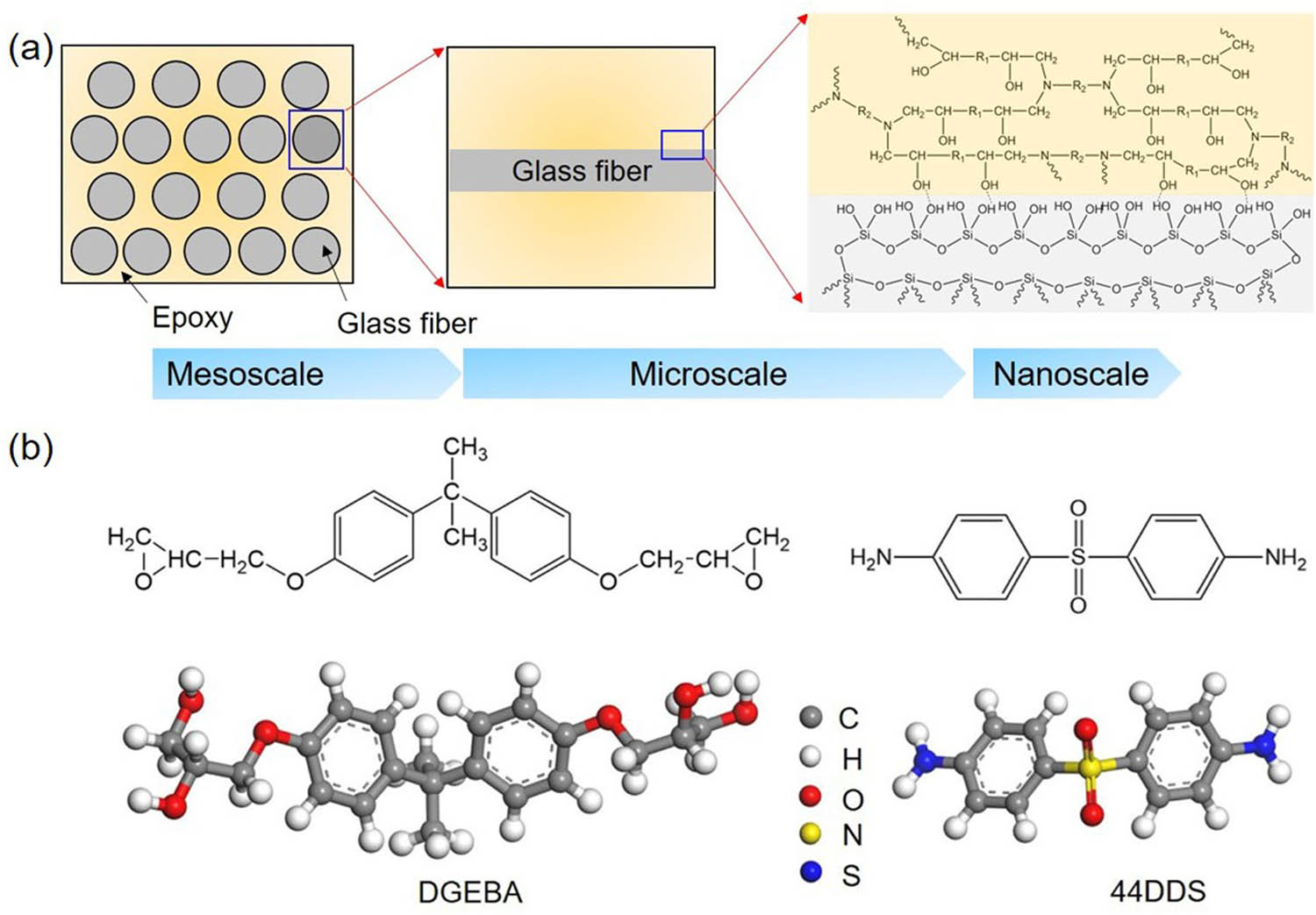
(a) Multiscale structures of glass fiber-reinforced epoxy composites. (b) Molecular structures of DGEBA and 44DDS monomers of cross-linked epoxy.
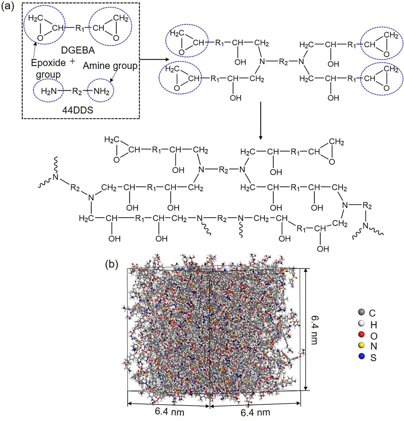
(a) Mechanism of cross-linking reaction between DGEBA and curing agent 44DDS. Parts of epoxy groups are open and activated to react with amine primary hydrogens in 44DDS resulting in the formation of secondary amine. The secondary amine can continue to react with opened epoxy groups. Finally, a cross-linked structure through the reaction between the open epoxy group in DGEBA and amine groups in 44DDS is formed. (b) The cross-linked epoxy structure.
We start to construct the cross-linked epoxy structure by packing activated DGEBA (C–O–C bonds in epoxide groups are broken and the hydroxyl groups are attached at the activated CH2 site.) with 44DDS using the amorphous cell module in Materials Studio. The stoichiometric mixing ratio of DGEBA to 44DDS is 2:1 with 400 monomers of DGEBA and 200 monomers of 44DDS. A cubic primitive cell with a length of 6.4 nm is constructed. The energy and geometry of the system are minimized by the conjugate gradient method and then equilibrated at 300 K in the canonical (NVT) ensemble for 1 ns followed by another 1 ns equilibration in the isothermal–isobaric (NPT) ensemble at 300 K and 1 atm. Subsequently, the equilibrated system is heated to 400 K for cross-link. The condensation reaction occurs between the hydroxyl groups in open epoxide groups of DGEBA and hydrogens in amine groups of 44DDS at 400 K. The cross-linked structure is obtained with a cross-linking degree of 85%, as shown in Figure 2(b). Next the condensation reaction occurs within DGEBA monomers where the unreacted open epoxide groups change to inactivated epoxide groups through the condensation reaction between hydroxyl groups, meaning that DGEBA molecules are ended with epoxide groups. The system is finally cooled down to 300 K for equilibration in NPT ensemble. After equilibration, the obtained cross-linked structure is served as the initial structure of epoxy resin with a size of 6.4 nm × 6.4 nm × 6.4 nm.
The physical properties of epoxy resin are predicted in LAMMPS. The cross-linked structure obtained from Materials Studio is first minimized and equilibrated for 1 ns in NVT ensemble at 300 K, then equilibrated for another 1 ns in NPT ensemble at 300 K and 1 atm. The purpose of doing NVT before NPT is based on algorithmic stability. Velocity generation in MD simulations can crash if coupled directly with a barostat. The equilibration is often done under NVT for a period to get the velocity distribution reasonable, followed by NPT. The root-mean-square displacement (RMSD) is checked; it is found that the value of RMSD at the end of 500 ps is almost constant indicating that the system is equilibrated. The density of the cross-linked epoxy is about 1.14 g/cm3, located in the range of 1.1–1.4 g/cm3 tested by experiments [25,27]. The glass transition temperature (T g) and Young’s modulus (E) of the cross-linked epoxy are predicted. Specifically, the equilibrated structure is heated to 690 K and then cooled down to 200 K at a temperature step of 30 K with a cooling rate of 0.5 K/ps. At each temperature, an equilibration of 500 ps is performed using NPT ensemble at 1 atm, so that the predicted results can be directly compared with experimental data. The specific volume as a function of temperature is obtained to evaluate T g of cross-linked epoxy. The tensile deformation of the system is performed at 300 K and 1 atm where the system is deformed along z direction with a fixed strain rate of 108/s. The system is equilibrated for about 50 ps following each step of deformation. The stress under a specific strain is obtained from the average stress for the last 5 ps equilibration. The value of E is predicted from the stress–strain curve.
2.2 Construction of silica model
The β-cristobalite has a lattice constant of 7.16 Å with an oxygen-to-silicon ratio of 2:1 shown in Figure 3(a). The crystalline β-cristobalite system is cleaved on (001) plane. The dangling oxygen atoms on the (001) surface are all saturated by the hydrogen atoms and dangling silicon atoms are saturated by hydroxyl groups, as shown in Figure 3(b). The density of the surface hydroxyl groups is about 7.9/nm2, located in the range of the experimental results [28]. It is found that the surface of silica is covered, to some extent, with hydroxyl groups during the formation processes; and the overall coverage of hydroxyl groups on a surface ranges from 0 to 9.4/nm2 in experimental tests [29]. The silica is first equilibrated at 300 K in NVT ensemble for 1 ns, then equilibrated in NPT ensemble at 300 K and 1 atm for another 1 ns with the periodic boundary condition. The equilibrated system is then heated to 5,000 K for melting and equilibrated for 1 ns in NPT ensemble. Next the equilibrated silica is cooled down to 300 K at a rate of 5 K/ps and equilibrated at 300 K at 1 atm for 1 ns. The density of constructed silica is about 2.18 g/cm3, close to the experimental data [30].
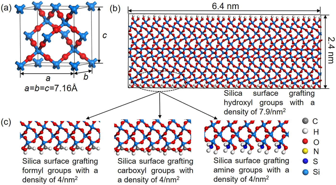
(a) The lattice structure of β-cristobalite. (b) The initial model of silica where the surface is covered by hydroxyl groups. It is obtained by cleaving on (001) surface of β-cristobalite and then the dangling oxygen on (001) surface are statured by hydrogen atoms and dangling silicon atoms are statured by hydroxyl groups. The density of hydroxyl groups on the silica surface is about 7.9/nm2. (c) The initial models of silica where the surface is covered by formyl group (COH), carboxyl group (COOH), and amine group (NH2), respectively. Such structures are obtained by replacing partial hydroxyl groups in (b). The density of these functional groups is about 4/nm2.
In order to study the effect of functional groups on the interfacial bonding, half of the number of hydroxyl groups on the surface of silica are randomly substituted by functional groups such as formyl groups, carboxyl groups, and amine groups with a density of 4/nm2. The silica models with different functional groups are equilibrated at 300 K and 1 atm in NPT ensemble for 1 ns. The RMSD is checked, and it is constant at the end of 500 ps, which indicates that the system is in an equilibrated state.
Radial distribution function (RDF) analysis is among one of the most important methods for revealing the structural features of a system and is calculated to quantify bond types. RDF is the probability density of finding atoms A and B at a distance r averaged over the equilibrium trajectory. Figure 4 shows the partial RDF of different silica systems. In the silica system with hydroxyl groups, the Si–O bond in inner silicon oxygen tetrahedron (bulk Si–O) and in silanol groups (Si–OH) are about 1.58 Å, as shown in Figure 4(a). This has a good agreement with the value (about 1.61 Å) measured by X-ray diffraction [31,32]. The length of bulk Si–O bond in silica models covered with formyl, carboxyl, and amine groups are similar to that in the silica models covered with hydroxyl groups as shown in Figure 4(b). The bond length of Si–N in the silica model covered with amine groups is around 1.68 Å, consistent with the value of 1.69 Å measured by experiments [33]. The length of Si–C in the silica model covered with formyl and carboxyl groups are 1.98 and 1.93 Å, respectively, in Figure 4(c), similar to those tested by experimental and computational approaches [34].
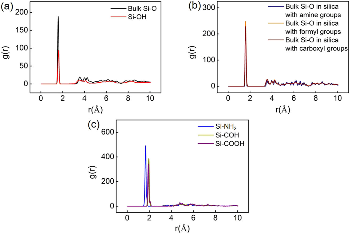
(a) The partial RDF of Si–O bond in silica model with the surface covered by hydroxyl groups. The length of the Si–O bond in silanol group (Si–OH) and in silicon oxygen tetrahedron (referring to bulk Si–O) is 1.58 Å, close to that measured by experiments. (b) The partial RDF of bulk Si–O bond in different silica models where the length of Si–O bond is close. (c) The partial RDF of Si–N and Si–C bonds in silica models with the surface covered by formyl, carboxyl, and amine groups. The length of the Si–N bond is about 1.68 Å. The length of the Si–C bond in silica with formyl and carboxyl groups are 1.98 Å and 1.93 Å, respectively, close to that measured by experiments.
2.3 Construction of epoxy/silica structure
The equilibrated epoxy, silica with different functional groups on the surface, and a vacuum layer with a thickness of 2 nm are sequentially placed in order from bottom to top with the formation of the complete simulation systems. The interlayer separation between silica and epoxy is initially selected to be 5 Å, which is subsequently adjusted by the repulsive and attractive forces at the interface during equilibration process. The periodic boundary conditions are applied in x, y, and z directions to avoid the finite-size effects. The vacuum layer added is in order to avoid the interfacial interaction caused by the periodic boundary condition in z direction. The interactions between epoxy and silica mainly consist of non-bonded interactions including the Coulomb interaction and van der Waals interaction. The constructed epoxy/silica system is first energy minimized, and then equilibrated at 300 K in NVT ensemble for 1 ns, followed by another 1 ns equilibration at 300 K and 1 atom in NPT ensemble. Finally, the RMSD is checked, and it is constant at the end of 500 ps, indicating that the system is in an equilibrated state.
The interfacial bonding energy of bilayer materials is calculated based on the formula [26]:
where E bonding is the interfacial bonding energy of the epoxy/silica system; E epoxy is the potential energy of the equilibrated epoxy system; E silica is the potential energy of the equilibrated silica system; E bilayer is the potential energy of the equilibrated epoxy/silica system and A is the interface area.
The interfacial debonding behavior of different bilayer systems is studied by pulling test using steered molecular dynamics (SMD) simulations. The SMD simulations, based on the principles of atomic force microscopy technique, can provide the conformational change in atomistic scale and energy variation during dynamic deformation [35]. In SMD simulations, the center-of-mass (COM) for epoxy and silica is attached by a virtual spring. The atoms are displaced by applying a constant velocity (v) to them. A restoring force is applied to the atoms and the magnitude of the force is related to the spring constant (k). The epoxy and silica are debonded along z direction under equivalent opposite force perpendicular to the interface. The virtual spring force is determined by ref. [36]:
where t is the time;
n
is a unit vector for the direction of pulling;
R
t
and
R
0 are the displacement at t and the initial displacement between the COM of epoxy and silica, respectively. U and F are the potential energy and virtual spring force, respectively. As shown in equations (2) and (3), the pulling force applied is dependent on the spring constant and the pulling velocity. If the spring constant is too small, the interface cannot be debonded. Otherwise, if the spring constant is too large or the pulling velocity is too fast, there is a problem to sample the interaction between fiber and epoxy along the pulling displacement. On the other hand, the velocity cannot be too small, considering the simulation time. Taking all these into consideration, we use the velocity of 1 Å/ps and a spring constant of 100 kcal/(mol · Å2) to ensure the high simulation accuracy and reasonable computational cost of simulations. The epoxy and silica are debonded along z direction under equivalent opposite force perpendicular to the interface. The pulling force F is collected every 0.1 fs. The initial length of the spring is equal to the initial displacement between the COM of epoxy and silica. As the value of COM for epoxy and silica along x and y directions are nearly the same, the variation in the distance between the COM of epoxy and silica along the z direction can be regarded as pulling displacement (d). This means that there is relationship of
3 Results and discussions
3.1 Physical properties of cross-linked epoxy
Figure 5 shows the partial RDF of bonds in epoxide groups and the cross-linked bonds between DGEBA and 44DDS. During the cross-linking process, the C–O bond in the epoxide group is broken as shown in Figure 5(a). The length of C–C and C–O bonds is 1.48 and 1.43 Å, respectively, as shown in Figure 5(b). The C–N bond is formed between DGEBA and 44DDS for cross-linking; its length is about 1.53 Å as shown in Figure 5(c). The bond lengths of C–C and C–O in open epoxide groups are 1.58 and 1.43 Å, respectively. These results are close to the experimental data, which are 1.47, 1.54, and 1.43 Å for C–N, C–C, and C–O bonds, respectively [38]. The variation in C–C bond in epoxide groups and open epoxide groups is correlated to the change in the type of linkage for the carbon atoms. The types of carbon atoms according to the PCFF forcefield are changed when the epoxide groups are open and cross-linked with amine groups.
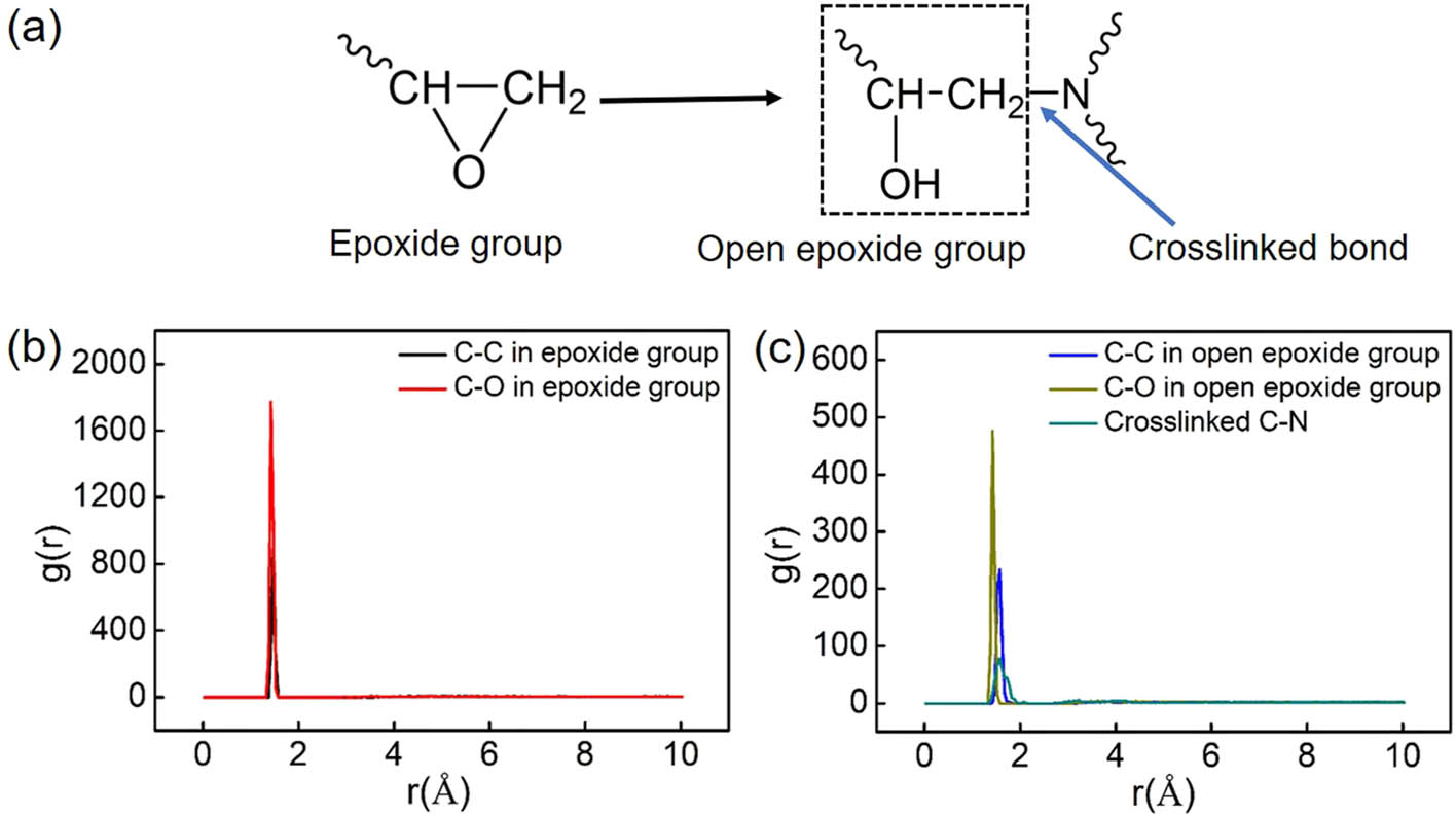
(a) The schematic diagram of bond change during cross-link. (b) The partial RDF of bonds in the epoxide group. The lengths of C–C and C–O bonds are 1.48 and 1.43 Å, respectively, close to those measured by experiments. (c) The partial RDF bonds in open epoxide groups. The lengths of C–C and C–O bonds are 1.58 and 1.43 Å. The cross-linked C–N bond between DGEBA monomer and 44DDS monomer is about 1.53 Å.
The physical and mechanical properties of the cross-linked epoxy have been predicted and compared with the experimental data for validation. Figure 6(a) shows the temperature dependence of the specific volume for the cross-linked epoxy during the cooling process. The specific volume of the cross-linked epoxy at each temperature has been calculated from the average density of the system for the last 50 ps of equilibration. The abrupt change in the slope of the curve determines T g. The intersect of the extrapolations denotes that T g of the cross-linked epoxy is about 489 K, located in the range from 460 to 530 K tested by the experimental approach [22,26,39]. Figure 6(b) shows the stress–strain curve of the tensile deformation for the cross-linked epoxy. Young’s modulus is about 4.4 GPa. This is located in the range of experimental results and close to other computational results [40,41]. All these indicate the reliability of PCFF in terms of predicting the mechanical properties of the modeled cross-linked epoxy. As the functional groups introduced on the surface of glass fiber mainly affect the conformational change in epoxy during debonding, a reasonable selection of forcefield to describe the epoxy properties is important.
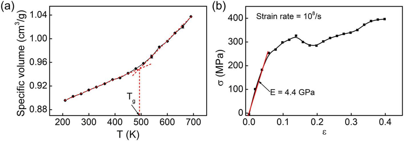
(a) The curve of specific volume as a function of temperature for the cross-linked epoxy. T g of the cross-linked epoxy is about 489 K, close to the experimental result. (b) The stress–strain curve of the cross-linked epoxy under a fixed strain rate of 108/s. Young’s modulus is about 4.4 GPa.
3.2 Interfacial properties of epoxy/silica systems
The effect of interfacial properties between epoxy and functionalized silica is investigated by performing the pulling test. The pulling force and PMF as a function of pulling distance are shown in Figure 7. In the pulling test, the force first increases linearly with pulling displacement, and the functional groups effect can be negligible as shown in Figure 7(b). The force, then, increases nonlinearly to reach the maximum. The maximum force (F
max) is different, indicating that the functional groups affect the force for the interface failure. The maximum force has a relationship
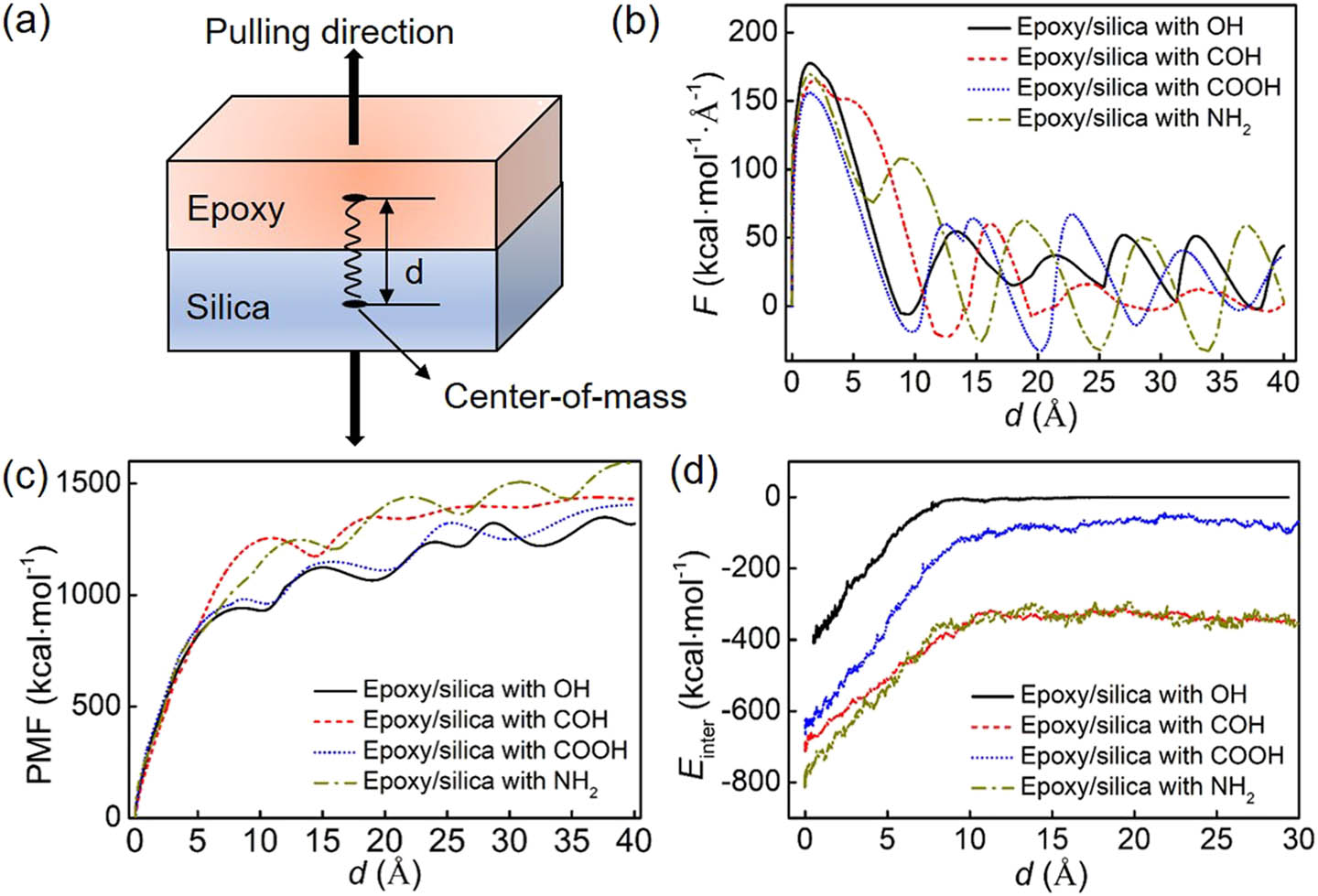
(a) The schematic diagram of pulling for epoxy/silica systems. (b) The curve of pulling force as a function of pulling displacement. (c) The curve of PMF as a function of pulling displacement. When the PMF reaches the first peak, the pulling force can be negligible indicating the failure of the interface. (d) The curve of interfacial interactions (E inter) as a function of pulling displacement for different systems during debonding.
The interfacial bonding energy, the value of F
max, PMFpeak, and corresponding d
0 for different bilayer systems are shown in Table 1. The interfacial bonding energy for different systems has a relationship of
The interfacial properties of different epoxy/silica systems, including the functional groups density, interfacial bonding energy (E bonding), the maximum pulling force (F max), the PMF for debonding (PMFpeak), and the corresponding pulling displacement (d0 )
| Model | Functional group density | F max (kcal · mol−1 · Å−1) | PMFpeak (kcal · mol−1) | d 0 (Å) | E bonding (kcal · mol−1 · nm−2) | |
|---|---|---|---|---|---|---|
| System 1 | OH | 177.60 ± 5.70 | 939.68 ± 30.24 | 7.96 ± 0.11 | 262.17 ± 3.13 | |
| 7.9/nm2 | ||||||
| System 2 | OH | COH | 164.77 ± 7.57 | 1,255.78 ± 30.41 | 10.95 ± 0.01 | 80.12 ± 3.68 |
| 4/nm2 | 4/nm2 | |||||
| System 3 | OH | COOH | 155.97 ± 2.35 | 982.25 ± 29.24 | 8.73 ± 0.25 | 77.63 ± 1.25 |
| 4/nm2 | 4/nm2 | |||||
| System 4 | OH | NH2 | 169.47 ± 2.92 | 1,223 ± 28.11 | 13.19 ± 0.08 | 168.79 ± 2.37 |
| 4/nm2 | 4/nm2 | |||||
The conformational changes at different displacements are represented to figure out the reason for the change in force and energy. Figure 8 shows the conformation of the epoxy/silica system with hydroxyl groups system at different pulling displacements. After the force reaches the peak, with the continuous increment in displacement, micropores are generated between epoxy and silica as shown in Figure 8(b). These micropores grow (Figure 8c) resulting in the debonding between epoxy and silica at the point of PMFpeak (Figure 8d). The interface fails at the contact surface between epoxy and silica; the debonded interface is relatively smooth as shown in Figure 8(e). The conformational change in the epoxy/silica with formyl, carboxyl, and amine groups during pulling is shown in Figure 9. Different from the system with hydroxyl groups, the interface fails in the epoxy close to the interface for these surface-modified systems. Specifically, the interface failure of the system with formyl groups is mainly due to the localized growth of micropores as shown in Figure 9(b). When the interface fails, some polymer chains of epoxy are still bonded to the silica as shown in Figure 9(c). For the system with carboxyl groups, the growth of micropores is associated with more micropores formed (Figure 9e). The number of micropores is much larger than that in the system with formyl groups at the same displacement. The coupled effect of formation and growth of micropores leads to the failure of interface with a few polymer chains bonded to silica (Figure 9f). However, after the micropores formed in the system with amine groups (Figure 9g), the size of some micropores is reduced with the increment in displacement as shown in Figure 9(h). A great number of polymer chains are still bonded to silica when the interface fails as shown in Figure 9(i). This indicates that a stronger interfacial interaction can prevent the mobility of polymer chains, inhibit the generation and growth of micropores, and even repair the micropores.
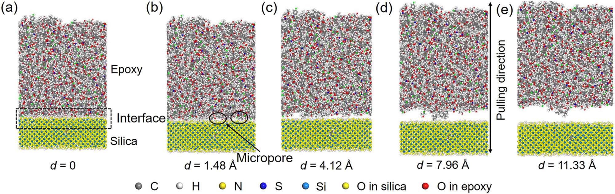
The structural evaluation of the interface in the epoxy/silica with hydroxyl groups. (a) The initial equilibrated system; (b) the generation of micropores; (c) the generation and growth of micropores; (d) the conformation at the point of PMFpeak where the interface fails at the contact surface between epoxy and silica; and (d) the conformation when the epoxy and silica are completely debonded.
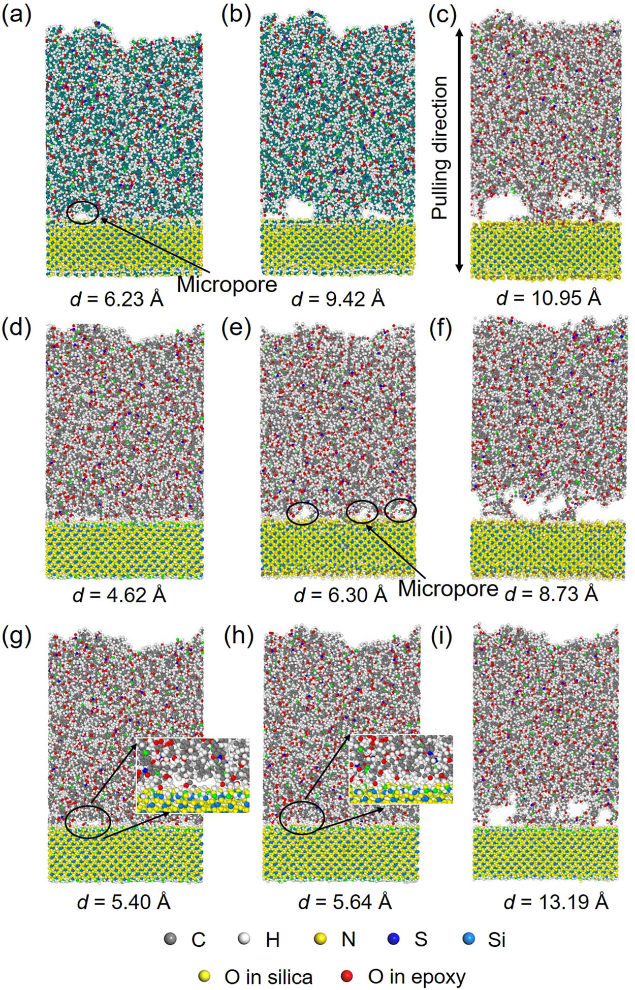
The structural evaluation of the interface in different systems. For the system with formyl groups, (a) the formation of micropores; (b) the growth of micropores; and (c) the failed interfacial structures at the point of PMFpeak. For the system with carboxyl groups, (d) the formation of micropores; (e) the generation and growth of multi micropores; and (f) the failed interfacial structures at the point of PMFpeak. For the system with amine groups, (g) the formation of micropores; (h) the reduction in micropore size; and (i) the failed interfacial structures with a great number of polymer chains in epoxy still bonded to silica.
For a better understanding of the conformational change in epoxy during deformation, the radius of gyration (R g) of the epoxy is quantified and calculated by:
where M is the total mass of epoxy; r cm is the COM position of the group; r i is the position of atom i; m i is the mass of atom i; and the sum is the overall atoms in the epoxy. This parameter can be used to evaluate the degree of compression and stretch for polymer chains. Figure 10 shows the curves of R g as a function of pulling displacement d. The R g of the system with hydroxyl groups first increases, and then almost keeps constant as shown in Figure 10(a). However, it reduces significantly to reach the minimum value. This rapid reduction is correlated to the failure mode. When the interface between epoxy and silica is debonded, the motion of polymer chains in epoxy is no longer constrained by the interfacial interactions, and R g reaches the minimum at the point of PMFpeak. The R g of the system with formyl groups is first increased followed by a decrease as shown in Figure 10(b). The reduction of R g is correlated to the constraint of polymer chains from the silica is reduced with the growth of micropores. The micropores generated in the epoxy close to the interface cause the increment in R g. When the interface fails, R g reaches to the minima due to a significant release of constraint. For the system with carboxyl groups, the R g fluctuates obviously before the interface fails in Figure 10(c). This is correlated to the formation and growth of multi micropores at the contact surface between epoxy and silica and in the epoxy near the interface. The R g of the system with amine groups first increases and then reduces slightly in Figure 10(d). The reduction is correlated to the formation of micropores. However, different from the system with hydroxyl, formyl, and carboxyl groups, the R g keeps growing with the increase in the displacement after the point of PMFpeak. This is mainly correlated to the increased number of polymer chains bonded to silica, where there is still a strong interfacial interaction between epoxy and silica when the interface is completely debonded. Generally, R g first increases rapidly when the force grows linearly at the beginning stage. The reduction in R g is correlated to the constraint release from silica caused by the generation and growth of micropores near the interface. However, a strong interfacial interaction promotes the growth of micropores within the epoxy matrix far from the interface, leading to an increment in R g.
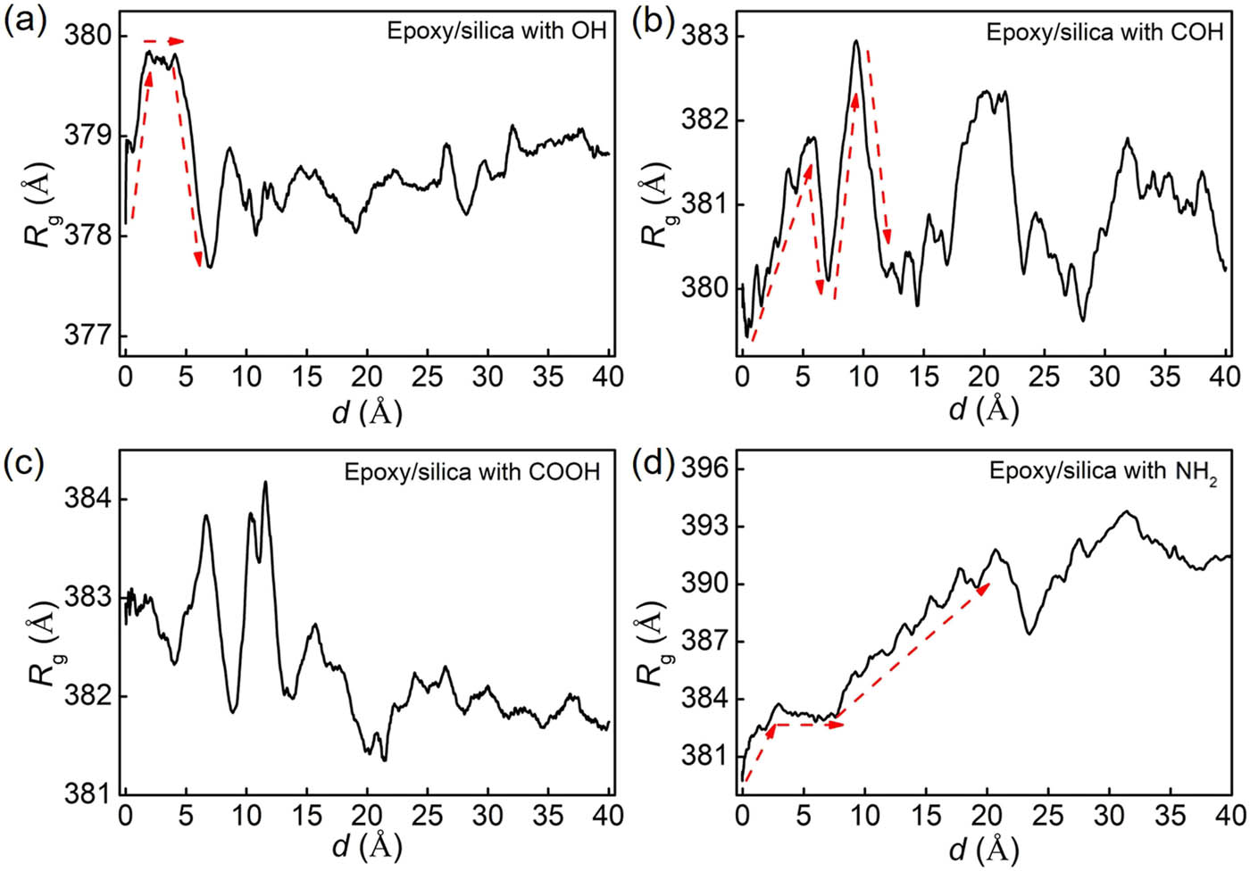
R g of epoxy as a function of displacement during pulling for (a) the system with hydroxyl groups; (b) the system with formyl groups; (c) the system with carboxyl groups; and (d) the system with amine groups. R g increases obviously at the beginning stage of pulling, consistent with the linear increment in pulling force. When the interface fails, R g reaches the local minima.
3.3 Failure mechanism of surface-modified GFR epoxy
The functional groups introduced on the surface of glass fiber change the interfacial interaction, significantly affecting the interface debonding behavior. As shown in Figure 11, there are two types of debonding failure mode for GFR epoxy at nanoscale: adhesive failure at the interface between epoxy and glass fiber, and cohesive failure in the epoxy matrix. Generally, higher stress is required for the adhesive failure mode, while more energy is absorbed for the cohesive failure mode. Because the increased interfacial interactions between epoxy and silica can prevent the debonding that occurred at the contact surface between epoxy and silica, the matrix has the lowest strength, causing a cohesive failure mode. A stronger interfacial adhesion prevents the mobility of polymer chains, inhibiting the generation and growth of micropores near the interface, leading to more micropores generated in the matrix far from the interface. More energy can be absorbed for the interface debonding. For example, the introduction of amine groups on the surface contributes to the improvement in the ability of energy absorption, resulting in a much larger displacement for interface debonding. Such failure mode is expected because GFR epoxy composites have a high ability of energy absorption and the components made up of such composites can avoid the catastrophic failures caused by the localized failure, making them reliable. Moreover, the cohesive failure of interface debonding can make it difficult for fiber pull-out that initiates from debonding between epoxy and glass fiber. Additionally, when the interfacial debonding occurs in the epoxy close to the interface, methods can be applied to improve the properties of epoxy. For example, the cross-linking degree of the epoxy matrix can be improved to decrease the speed of micropore growth. The reinforcements such as carbon nanotubes [42] and graphene [43] can be added to inhibit micropore growth in the matrix for optimizing the performance of GFR composites.
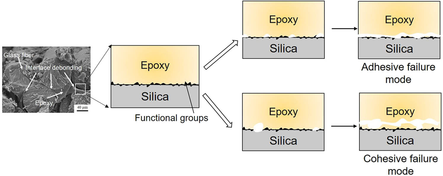
The surface-modified GFR epoxy composites exhibit two types of interface debonding: adhesive failure mode and cohesive failure mode. The introduction of functional groups significantly affects the interface failure mode. The strong interfacial interactions between epoxy and silica prevent the debonding at the contact surface between epoxy and silica, leading to a cohesive failure mode.
In this work, we mainly consider the non-bonded interactions between glass fiber and epoxy matrix. In practice, the glass fiber surface modification changes not only the interfacial interaction but also the surface morphology of fiber and chemical reactivity along the fiber-matrix interface [44]. The surface roughness and the chemical bonds between epoxy and surface-modified glass fiber are not considered, because the main purpose of modification of the surface characteristics of glass fiber is to improve the compatibility or wettability between glass fiber and epoxy matrix. The naturally hydrophilic epoxy is not inherently compatible with hydrophobic glass fiber. Composites with improved wettability can have superior interfacial bonding. Moreover, the effect of roughness on interfacial adhesion is complicated. An increment in surface roughness of glass fiber contributes to the mechanical interlocking between fiber and polymer matrix. However, with a further increase in surface roughness, the fiber is damaged with a reduction in mechanical properties. Compared with the non-bonded interfacial interactions, the chemical bonds at interface and the surface roughness are more difficult to be controlled. For surface modification techniques, the factors affecting the interfacial bonding between fiber and matrix include mechanical interlocking, physical binding, and chemical bonding. Our simulated work on the physical binding effect between glass fiber and polymer matrix lay a foundation to realize precise control over the interface adhesion of GFR composites. For the example of surface modification technique of plasma treatment, our results provide a guideline for the selection of the atmosphere parameter. A nitrogen atmosphere can be selected to introduce the amine groups on the silica surface for surface modification of glass fibers.
4 Conclusion
The surface modification techniques with the introduction of different functional groups have been widely applied to improve the interfacial bonding between the glass fiber and epoxy resin. However, as the underlying mechanism is still not fully understood, the surface modification is still based on the trial-and-error approach to obtain the optimum performance of GFR epoxy. The enhancement of interfacial properties for GFR epoxy by surface modification is limited. In this work, the effect of functional groups on the interfacial behavior between epoxy and silica at atomistic scale has been studied. The DGEBA and 44DDS are cross-linked to form epoxy resin. The interfacial properties of the epoxy/silica systems have been predicted by the pulling test using SMD simulations. Based on the findings, several conclusions can be drawn:
The epoxy/silica system with hydroxyl groups requires the highest force, but the shortest pulling displacement and the lowest energy for interface debonding. The system fails at the contact surface between epoxy and silica, exhibiting an adhesive failure mode.
When partial hydroxyl groups are replaced by formyl, carboxyl, and amine groups, respectively, the system fails in the epoxy close to the interface, representing a cohesive failure mode. Although the pulling force for debonding is reduced compared with that in the system with hydroxyl groups, more energy is absorbed for the rearrangement of polymer chains in epoxy.
When the epoxy/surface-modified silica system exhibits a cohesive failure mode, the force and energy for debonding are increased with the increment in the interface interactions. Compared with the system with carboxyl groups, the systems with amine and formyl groups require a relatively higher force and energy for debonding because of the stronger interfacial interaction.
Our work reveals the mechanism of different functional groups on the interfacial behavior of GFR epoxy. Such understanding is fundamental to figure out the reason for the variation in interfacial performance caused by different glass fiber surface modification techniques. The findings in this work lay a foundation for the accurate control of interfacial properties of GFR composites by surface modification.
-
Funding information: The work described in this article was fully supported by the grant from State Grid Electric Power Research Institute (Project Number: 524625190052), and the Natural Science Foundation of Huber Province (2021CFB137). The numerical calculations in this work have been done on the supercomputing system in the Supercomputing Center of Wuhan University.
-
Author contributions: All authors have accepted responsibility for the entire content of this manuscript and approved its submission.
-
Conflict of interest: The authors state no conflict of interest.
References
[1] Hu Z, Zhang D, Lu F, Yuan W, Xu X, Zhang Q, et al. Multistimuli-responsive intrinsic self-healing epoxy resin constructed by host-guest interactions. Macromolecules. 2018;51(14):5294–3.10.1021/acs.macromol.8b01124Search in Google Scholar
[2] Ma H, Zhang X, Ju F, Tsai SB. A study on curing kinetics of nano-phase modified epoxy resin. Sci Rep. 2018;8(1):3045.10.1038/s41598-018-21208-0Search in Google Scholar PubMed PubMed Central
[3] Rajak DK, Pagar DD, Menezes PL, Linul E. Fiber-reinforced polymer composites: manufacturing, properties, and applications. Polymers. 2019;11(10):1667.10.3390/polym11101667Search in Google Scholar PubMed PubMed Central
[4] Ren D, Li K, Chen L, Chen S, Han M, Xu M, et al. Modification on glass fiber surface and their improved properties of fiber-reinforced composites via enhanced interfacial properties. Compos Part B Eng. 2019;177:107419.10.1016/j.compositesb.2019.107419Search in Google Scholar
[5] Zhang H, Han W, Tavakoli J, Zhang Y-P, Lin X, Lu X, et al. Understanding interfacial interactions of polydopamine and glass fiber and their enhancement mechanisms in epoxy-based laminates. Compos Part A Appl Sci Manuf. 2019;116:62–71.10.1016/j.compositesa.2018.10.024Search in Google Scholar
[6] Jing M, Che J, Xu S, Liu Z, Fu Q. The effect of surface modification of glass fiber on the performance of poly(lactic acid) composites: Graphene oxide vs silane coupling agents. Appl Surf Sci. 2018;435:1046–56.10.1016/j.apsusc.2017.11.134Search in Google Scholar
[7] Huang J, Li W, Huang D, Wang L, Chen E, Wu CY, et al. Fractal analysis on pore structure and hydration of magnesium oxysulfate cements by first principle, thermodynamic and microstructure-based methods. Fractal Fract. 2021;5(4):164.10.3390/fractalfract5040164Search in Google Scholar
[8] Wu M, Jia L, Lu S, Qin Z, Wei S, Yan R. Interfacial performance of high-performance fiber-reinforced composites improved by cold plasma treatment: a review. Surf Interfaces. 2021;24:101077.10.1016/j.surfin.2021.101077Search in Google Scholar
[9] Abbas YM, Khan IM. Fiber-matrix interactions in fber-reinforced concrete: a review. Arab J Sci Eng. 2016;41(4):1183–98.10.1007/s13369-016-2099-1Search in Google Scholar
[10] Zhou Y, Fan M, Chen L. Interface and bonding mechanisms of plant fibre composites: an overview. Compos Part B: Eng. 2016;101:31–45.10.1016/j.compositesb.2016.06.055Search in Google Scholar
[11] Singh DK, Vaidya A, Thomas V, Theodore M, Kore S, Vaidya U. Finite element modeling of the fiber-matrix interface in polymer composites. J Compos Sci. 2020;4(2):58.10.3390/jcs4020058Search in Google Scholar
[12] Karger-Kocsis J, Mahmood H, Pegoretti A. Recent advances in fiber/matrix interphase engineering for polymer composites. Prog in Mater Sci. 2015;73:1–43.10.1016/j.pmatsci.2015.02.003Search in Google Scholar
[13] Hao H, Tam L-H, Lu Y, Lau An D. atomistic study on the mechanical behavior of bamboo cell wall constituents. Compos Part B Eng. 2018;151:222–31.10.1016/j.compositesb.2018.05.046Search in Google Scholar
[14] Hao H, Chow CL, Lau D. Carbon monoxide release mechanism in cellulose combustion using reactive forcefield. Fuel. 2020;269:117422.10.1016/j.fuel.2020.117422Search in Google Scholar
[15] Hao H, Hui D, Lau D. Material advancement in technological development for the 5G wireless communications. Nanotechnol Rev. 2020;9(1):683–99.10.1515/ntrev-2020-0054Search in Google Scholar
[16] Ju SP, Chen CC, Huang TJ, Liao CH, Chen HL, Chuang YC, et al. Investigation of the structural and mechanical properties of polypropylene-based carbon fiber nanocomposites by experimental measurement and molecular dynamics simulation. Comput Mater Sci. 2016;115:1–10.10.1016/j.commatsci.2015.12.032Search in Google Scholar
[17] Wang H, Jin K, Wang C, Guo X, Chen Z, Tao J. Effect of fiber surface functionalization on shear behavior at carbon fiber/epoxy interface through molecular dynamics analysis. Compos Part A Appl Sci Manuf. 2019;126:105611.10.1016/j.compositesa.2019.105611Search in Google Scholar
[18] Accelrys Software Inc.: Materials Studio 2007.Search in Google Scholar
[19] Plimpton S. Fast parallel algorithms for short-range molecular dynamics. J Comput Phys. 1995;117(1):1–19.10.2172/10176421Search in Google Scholar
[20] Hao H, Zhou W, Lu Y, Lau D. Atomic arrangement in CuZr-based metallic glass composites under tensile deformation. Phys Chem Chem Phys. 2019;22(1):313–24.10.1039/C9CP04914BSearch in Google Scholar PubMed
[21] Pramanik C, Nepal D, Nathanson M, Gissinger JR, Garley A, Berry RJ, et al. Molecular engineering of interphases in polymer/carbon nanotube composites to reach the limits of mechanical performance. Compos Sci Technol. 2018;166:86–94.10.1016/j.compscitech.2018.04.013Search in Google Scholar
[22] Amariutei OA, Ramsdale-Capper R, Correa Álvarez M, Chan LKY, Foreman JP. Modelling the properties of a difunctional epoxy resin cured with aromatic diamine isomers. Polymer. 2018;156:203–13.10.1016/j.polymer.2018.10.016Search in Google Scholar
[23] Leroch S, Wendland M. Simulation of forces between humid amorphous silica surfaces: a comparison of empirical atomistic force fields. J Phys Chem C. 2012;116(50):26247–61.10.1021/jp302428bSearch in Google Scholar
[24] Pedone A. Properties calculations of silica-based glasses by atomistic simulations techniques- a review. J Chem Phys. 2009;1136:20773–84.10.1021/jp9071263Search in Google Scholar
[25] Moller JC, Berry RJ, Foster HA. On the nature of epoxy resin post-curing. Polymers. 2020;12(2):466.10.3390/polym12020466Search in Google Scholar
[26] Fu K, Xie Q, Lu F, Duan Q, Wang X, Zhu Q, et al. Molecular dynamics simulation and experimental studies on the thermomechanical properties of epoxy resin with different anhydride curing agents. Polymers. 2019;11(6):975.10.3390/polym11060975Search in Google Scholar
[27] Becker O, Varley R, Simon G. Morphology, thermal relaxations and mechanical properties of layered silicate nanocomposites based upon high-functionality epoxy resins. Polymer. 2002;43:4365–73.10.1016/S0032-3861(02)00269-0Search in Google Scholar
[28] Patwardhan SV, Emami FS, Berry RJ, Jones SE, Naik RR, Deschaume O, et al. Chemistry of aqueous silica nanoparticle surfaces and the mechanism of selective peptide adsorption. J Am Chem Soc. 2012;134(14):6244–56.10.1021/ja211307uSearch in Google Scholar PubMed
[29] Thipperudrappa S, Ullal Kini A, Hiremath A. Influence of zinc oxide nanoparticles on the mechanical and thermal responses of glass fiber‐reinforced epoxy nanocomposites. Polym Compos. 2019;41(1):174–81.10.1002/pc.25357Search in Google Scholar
[30] Shrivastava A. Introduction to plastics engineering. 1st edn. Oxford: William Andrew; 2018.10.1016/B978-0-323-39500-7.00001-0Search in Google Scholar
[31] Rimsza JM, Jones RE, Criscenti LJ. Surface structure and stability of partially hydroxylated silica surfaces. Langmuir. 2017;33(15):3882–91.10.1021/acs.langmuir.7b00041Search in Google Scholar PubMed
[32] Kaliannan NK. Monte carlo simulations of amorphous hydroxylated silica (SiO2) nanoparticles. Comput Mater Sci. 2017;135:90–8.10.1016/j.commatsci.2017.04.004Search in Google Scholar
[33] Ippolito MMeloni S. Atomistic structure of amorphous silicon nitride from classical molecular dynamics simulations. Phys Rev B. 2011;83:165209.10.1103/PhysRevB.83.165209Search in Google Scholar
[34] Campanelli AR. Stereoelectronic effects in the Si–C bond: a study of the molecular structure and conformation of tetraphenylsilane by gas-phase electron diffraction and theoretical calculations. J Phys Chem. 2001;105(24):5933–9.10.1021/jp010259jSearch in Google Scholar
[35] Min K, Kim Y, Goyal S, Lee SH, McKenzie M, Park H, et al. Interfacial adhesion behavior of polyimides on silica glass: a molecular dynamics study. Polymer. 2016;98:1–10.10.1016/j.polymer.2016.06.017Search in Google Scholar
[36] Sun Q, Zhao Y, Choi K-S, Hou X, Mao X. Reduction of atomistic ice tensile stress by graphene–carbon nanotube coating. Appl Surf Sci. 2021;565:150562.10.1016/j.apsusc.2021.150562Search in Google Scholar
[37] Cruz-Chú ER, Villegas-Rodríguez GJ, Jäger T, Valentini L, Pugno NM, Gkagkas K, et al. Mechanical characterization and induced crystallization in nanocomposites of thermoplastics and carbon nanotubes. Npj Comput Mater. 2020;6(1):151.10.1038/s41524-020-00420-5Search in Google Scholar
[38] Lu N, Li ZY, Yang JL. Structure of graphene oxide: thermodynamics versus kinetics. J Phys Chem. 2011;115(24):11991–5.10.1021/jp204476qSearch in Google Scholar
[39] Jin K, Luo H, Wang Z, Wang H, Tao J. Composition optimization of a high-performance epoxy resin based on molecular dynamics and machine learning. Mater Des. 2020;194:108932.10.1016/j.matdes.2020.108932Search in Google Scholar
[40] Xie Q, Fu K, Liang S, Liu B, Lu L, Yang X, et al. Micro-structure and thermomechanical properties of crosslinked epoxy composite modified by nano-SiO2: a molecular dynamics simulation. Polymers. 2018;10(7):801.10.3390/polym10070801Search in Google Scholar PubMed PubMed Central
[41] Jeyranpour F, Alahyarizadeh G, Arab B. Comparative investigation of thermal and mechanical properties of cross-linked epoxy polymers with different curing agents by molecular dynamics simulation. J Mol Graph Model. 2015;62:157–64.10.1016/j.jmgm.2015.09.012Search in Google Scholar PubMed
[42] Pan S, Dai Q, Safaei B, Qin Z, Chu F. Damping characteristics of carbon nanotube reinforced epoxy nanocomposite beams. Thin-Walled Struct. 2021;166:108127.10.1016/j.tws.2021.108127Search in Google Scholar
[43] Wang Y, Ermilov V, Strigin S, Safaei B. Multilevel modeling of the mechanical properties of graphene nanocomposites/polymer composites. Microsyst Technol. 2021;27(12):4241–51.10.1007/s00542-021-05218-zSearch in Google Scholar
[44] Cho K, Wang G, Raju Fang J, Rajan G, Stenzel MH, Farrar P, et al. Selective atomic-level etching on short S-glass fibres to control interfacial properties for restorative dental composites. Sci Rep. 2019;9(1):3851.10.1038/s41598-019-40524-7Search in Google Scholar PubMed PubMed Central
© 2022 Jiangang Deng et al., published by De Gruyter
This work is licensed under the Creative Commons Attribution 4.0 International License.
Articles in the same Issue
- Research Articles
- Theoretical and experimental investigation of MWCNT dispersion effect on the elastic modulus of flexible PDMS/MWCNT nanocomposites
- Mechanical, morphological, and fracture-deformation behavior of MWCNTs-reinforced (Al–Cu–Mg–T351) alloy cast nanocomposites fabricated by optimized mechanical milling and powder metallurgy techniques
- Flammability and physical stability of sugar palm crystalline nanocellulose reinforced thermoplastic sugar palm starch/poly(lactic acid) blend bionanocomposites
- Glutathione-loaded non-ionic surfactant niosomes: A new approach to improve oral bioavailability and hepatoprotective efficacy of glutathione
- Relationship between mechano-bactericidal activity and nanoblades density on chemically strengthened glass
- In situ regulation of microstructure and microwave-absorbing properties of FeSiAl through HNO3 oxidation
- Research on a mechanical model of magnetorheological fluid different diameter particles
- Nanomechanical and dynamic mechanical properties of rubber–wood–plastic composites
- Investigative properties of CeO2 doped with niobium: A combined characterization and DFT studies
- Miniaturized peptidomimetics and nano-vesiculation in endothelin types through probable nano-disk formation and structure property relationships of endothelins’ fragments
- N/S co-doped CoSe/C nanocubes as anode materials for Li-ion batteries
- Synergistic effects of halloysite nanotubes with metal and phosphorus additives on the optimal design of eco-friendly sandwich panels with maximum flame resistance and minimum weight
- Octreotide-conjugated silver nanoparticles for active targeting of somatostatin receptors and their application in a nebulized rat model
- Controllable morphology of Bi2S3 nanostructures formed via hydrothermal vulcanization of Bi2O3 thin-film layer and their photoelectrocatalytic performances
- Development of (−)-epigallocatechin-3-gallate-loaded folate receptor-targeted nanoparticles for prostate cancer treatment
- Enhancement of the mechanical properties of HDPE mineral nanocomposites by filler particles modulation of the matrix plastic/elastic behavior
- Effect of plasticizers on the properties of sugar palm nanocellulose/cinnamon essential oil reinforced starch bionanocomposite films
- Optimization of nano coating to reduce the thermal deformation of ball screws
- Preparation of efficient piezoelectric PVDF–HFP/Ni composite films by high electric field poling
- MHD dissipative Casson nanofluid liquid film flow due to an unsteady stretching sheet with radiation influence and slip velocity phenomenon
- Effects of nano-SiO2 modification on rubberised mortar and concrete with recycled coarse aggregates
- Mechanical and microscopic properties of fiber-reinforced coal gangue-based geopolymer concrete
- Effect of morphology and size on the thermodynamic stability of cerium oxide nanoparticles: Experiment and molecular dynamics calculation
- Mechanical performance of a CFRP composite reinforced via gelatin-CNTs: A study on fiber interfacial enhancement and matrix enhancement
- A practical review over surface modification, nanopatterns, emerging materials, drug delivery systems, and their biophysiochemical properties for dental implants: Recent progresses and advances
- HTR: An ultra-high speed algorithm for cage recognition of clathrate hydrates
- Effects of microalloying elements added by in situ synthesis on the microstructure of WCu composites
- A highly sensitive nanobiosensor based on aptamer-conjugated graphene-decorated rhodium nanoparticles for detection of HER2-positive circulating tumor cells
- Progressive collapse performance of shear strengthened RC frames by nano CFRP
- Core–shell heterostructured composites of carbon nanotubes and imine-linked hyperbranched polymers as metal-free Li-ion anodes
- A Galerkin strategy for tri-hybridized mixture in ethylene glycol comprising variable diffusion and thermal conductivity using non-Fourier’s theory
- Simple models for tensile modulus of shape memory polymer nanocomposites at ambient temperature
- Preparation and morphological studies of tin sulfide nanoparticles and use as efficient photocatalysts for the degradation of rhodamine B and phenol
- Polyethyleneimine-impregnated activated carbon nanofiber composited graphene-derived rice husk char for efficient post-combustion CO2 capture
- Electrospun nanofibers of Co3O4 nanocrystals encapsulated in cyclized-polyacrylonitrile for lithium storage
- Pitting corrosion induced on high-strength high carbon steel wire in high alkaline deaerated chloride electrolyte
- Formulation of polymeric nanoparticles loaded sorafenib; evaluation of cytotoxicity, molecular evaluation, and gene expression studies in lung and breast cancer cell lines
- Engineered nanocomposites in asphalt binders
- Influence of loading voltage, domain ratio, and additional load on the actuation of dielectric elastomer
- Thermally induced hex-graphene transitions in 2D carbon crystals
- The surface modification effect on the interfacial properties of glass fiber-reinforced epoxy: A molecular dynamics study
- Molecular dynamics study of deformation mechanism of interfacial microzone of Cu/Al2Cu/Al composites under tension
- Nanocolloid simulators of luminescent solar concentrator photovoltaic windows
- Compressive strength and anti-chloride ion penetration assessment of geopolymer mortar merging PVA fiber and nano-SiO2 using RBF–BP composite neural network
- Effect of 3-mercapto-1-propane sulfonate sulfonic acid and polyvinylpyrrolidone on the growth of cobalt pillar by electrodeposition
- Dynamics of convective slippery constraints on hybrid radiative Sutterby nanofluid flow by Galerkin finite element simulation
- Preparation of vanadium by the magnesiothermic self-propagating reduction and process control
- Microstructure-dependent photoelectrocatalytic activity of heterogeneous ZnO–ZnS nanosheets
- Cytotoxic and pro-inflammatory effects of molybdenum and tungsten disulphide on human bronchial cells
- Improving recycled aggregate concrete by compression casting and nano-silica
- Chemically reactive Maxwell nanoliquid flow by a stretching surface in the frames of Newtonian heating, nonlinear convection and radiative flux: Nanopolymer flow processing simulation
- Nonlinear dynamic and crack behaviors of carbon nanotubes-reinforced composites with various geometries
- Biosynthesis of copper oxide nanoparticles and its therapeutic efficacy against colon cancer
- Synthesis and characterization of smart stimuli-responsive herbal drug-encapsulated nanoniosome particles for efficient treatment of breast cancer
- Homotopic simulation for heat transport phenomenon of the Burgers nanofluids flow over a stretching cylinder with thermal convective and zero mass flux conditions
- Incorporation of copper and strontium ions in TiO2 nanotubes via dopamine to enhance hemocompatibility and cytocompatibility
- Mechanical, thermal, and barrier properties of starch films incorporated with chitosan nanoparticles
- Mechanical properties and microstructure of nano-strengthened recycled aggregate concrete
- Glucose-responsive nanogels efficiently maintain the stability and activity of therapeutic enzymes
- Tunning matrix rheology and mechanical performance of ultra-high performance concrete using cellulose nanofibers
- Flexible MXene/copper/cellulose nanofiber heat spreader films with enhanced thermal conductivity
- Promoted charge separation and specific surface area via interlacing of N-doped titanium dioxide nanotubes on carbon nitride nanosheets for photocatalytic degradation of Rhodamine B
- Elucidating the role of silicon dioxide and titanium dioxide nanoparticles in mitigating the disease of the eggplant caused by Phomopsis vexans, Ralstonia solanacearum, and root-knot nematode Meloidogyne incognita
- An implication of magnetic dipole in Carreau Yasuda liquid influenced by engine oil using ternary hybrid nanomaterial
- Robust synthesis of a composite phase of copper vanadium oxide with enhanced performance for durable aqueous Zn-ion batteries
- Tunning self-assembled phases of bovine serum albumin via hydrothermal process to synthesize novel functional hydrogel for skin protection against UVB
- A comparative experimental study on damping properties of epoxy nanocomposite beams reinforced with carbon nanotubes and graphene nanoplatelets
- Lightweight and hydrophobic Ni/GO/PVA composite aerogels for ultrahigh performance electromagnetic interference shielding
- Research on the auxetic behavior and mechanical properties of periodically rotating graphene nanostructures
- Repairing performances of novel cement mortar modified with graphene oxide and polyacrylate polymer
- Closed-loop recycling and fabrication of hydrophilic CNT films with high performance
- Design of thin-film configuration of SnO2–Ag2O composites for NO2 gas-sensing applications
- Study on stress distribution of SiC/Al composites based on microstructure models with microns and nanoparticles
- PVDF green nanofibers as potential carriers for improving self-healing and mechanical properties of carbon fiber/epoxy prepregs
- Osteogenesis capability of three-dimensionally printed poly(lactic acid)-halloysite nanotube scaffolds containing strontium ranelate
- Silver nanoparticles induce mitochondria-dependent apoptosis and late non-canonical autophagy in HT-29 colon cancer cells
- Preparation and bonding mechanisms of polymer/metal hybrid composite by nano molding technology
- Damage self-sensing and strain monitoring of glass-reinforced epoxy composite impregnated with graphene nanoplatelet and multiwalled carbon nanotubes
- Thermal analysis characterisation of solar-powered ship using Oldroyd hybrid nanofluids in parabolic trough solar collector: An optimal thermal application
- Pyrene-functionalized halloysite nanotubes for simultaneously detecting and separating Hg(ii) in aqueous media: A comprehensive comparison on interparticle and intraparticle excimers
- Fabrication of self-assembly CNT flexible film and its piezoresistive sensing behaviors
- Thermal valuation and entropy inspection of second-grade nanoscale fluid flow over a stretching surface by applying Koo–Kleinstreuer–Li relation
- Mechanical properties and microstructure of nano-SiO2 and basalt-fiber-reinforced recycled aggregate concrete
- Characterization and tribology performance of polyaniline-coated nanodiamond lubricant additives
- Combined impact of Marangoni convection and thermophoretic particle deposition on chemically reactive transport of nanofluid flow over a stretching surface
- Spark plasma extrusion of binder free hydroxyapatite powder
- An investigation on thermo-mechanical performance of graphene-oxide-reinforced shape memory polymer
- Effect of nanoadditives on the novel leather fiber/recycled poly(ethylene-vinyl-acetate) polymer composites for multifunctional applications: Fabrication, characterizations, and multiobjective optimization using central composite design
- Design selection for a hemispherical dimple core sandwich panel using hybrid multi-criteria decision-making methods
- Improving tensile strength and impact toughness of plasticized poly(lactic acid) biocomposites by incorporating nanofibrillated cellulose
- Green synthesis of spinel copper ferrite (CuFe2O4) nanoparticles and their toxicity
- The effect of TaC and NbC hybrid and mono-nanoparticles on AA2024 nanocomposites: Microstructure, strengthening, and artificial aging
- Excited-state geometry relaxation of pyrene-modified cellulose nanocrystals under UV-light excitation for detecting Fe3+
- Effect of CNTs and MEA on the creep of face-slab concrete at an early age
- Effect of deformation conditions on compression phase transformation of AZ31
- Application of MXene as a new generation of highly conductive coating materials for electromembrane-surrounded solid-phase microextraction
- A comparative study of the elasto-plastic properties for ceramic nanocomposites filled by graphene or graphene oxide nanoplates
- Encapsulation strategies for improving the biological behavior of CdS@ZIF-8 nanocomposites
- Biosynthesis of ZnO NPs from pumpkin seeds’ extract and elucidation of its anticancer potential against breast cancer
- Preliminary trials of the gold nanoparticles conjugated chrysin: An assessment of anti-oxidant, anti-microbial, and in vitro cytotoxic activities of a nanoformulated flavonoid
- Effect of micron-scale pores increased by nano-SiO2 sol modification on the strength of cement mortar
- Fractional simulations for thermal flow of hybrid nanofluid with aluminum oxide and titanium oxide nanoparticles with water and blood base fluids
- The effect of graphene nano-powder on the viscosity of water: An experimental study and artificial neural network modeling
- Development of a novel heat- and shear-resistant nano-silica gelling agent
- Characterization, biocompatibility and in vivo of nominal MnO2-containing wollastonite glass-ceramic
- Entropy production simulation of second-grade magnetic nanomaterials flowing across an expanding surface with viscidness dissipative flux
- Enhancement in structural, morphological, and optical properties of copper oxide for optoelectronic device applications
- Aptamer-functionalized chitosan-coated gold nanoparticle complex as a suitable targeted drug carrier for improved breast cancer treatment
- Performance and overall evaluation of nano-alumina-modified asphalt mixture
- Analysis of pure nanofluid (GO/engine oil) and hybrid nanofluid (GO–Fe3O4/engine oil): Novel thermal and magnetic features
- Synthesis of Ag@AgCl modified anatase/rutile/brookite mixed phase TiO2 and their photocatalytic property
- Mechanisms and influential variables on the abrasion resistance hydraulic concrete
- Synergistic reinforcement mechanism of basalt fiber/cellulose nanocrystals/polypropylene composites
- Achieving excellent oxidation resistance and mechanical properties of TiB2–B4C/carbon aerogel composites by quick-gelation and mechanical mixing
- Microwave-assisted sol–gel template-free synthesis and characterization of silica nanoparticles obtained from South African coal fly ash
- Pulsed laser-assisted synthesis of nano nickel(ii) oxide-anchored graphitic carbon nitride: Characterizations and their potential antibacterial/anti-biofilm applications
- Effects of nano-ZrSi2 on thermal stability of phenolic resin and thermal reusability of quartz–phenolic composites
- Benzaldehyde derivatives on tin electroplating as corrosion resistance for fabricating copper circuit
- Mechanical and heat transfer properties of 4D-printed shape memory graphene oxide/epoxy acrylate composites
- Coupling the vanadium-induced amorphous/crystalline NiFe2O4 with phosphide heterojunction toward active oxygen evolution reaction catalysts
- Graphene-oxide-reinforced cement composites mechanical and microstructural characteristics at elevated temperatures
- Gray correlation analysis of factors influencing compressive strength and durability of nano-SiO2 and PVA fiber reinforced geopolymer mortar
- Preparation of layered gradient Cu–Cr–Ti alloy with excellent mechanical properties, thermal stability, and electrical conductivity
- Recovery of Cr from chrome-containing leather wastes to develop aluminum-based composite material along with Al2O3 ceramic particles: An ingenious approach
- Mechanisms of the improved stiffness of flexible polymers under impact loading
- Anticancer potential of gold nanoparticles (AuNPs) using a battery of in vitro tests
- Review Articles
- Proposed approaches for coronaviruses elimination from wastewater: Membrane techniques and nanotechnology solutions
- Application of Pickering emulsion in oil drilling and production
- The contribution of microfluidics to the fight against tuberculosis
- Graphene-based biosensors for disease theranostics: Development, applications, and recent advancements
- Synthesis and encapsulation of iron oxide nanorods for application in magnetic hyperthermia and photothermal therapy
- Contemporary nano-architectured drugs and leads for ανβ3 integrin-based chemotherapy: Rationale and retrospect
- State-of-the-art review of fabrication, application, and mechanical properties of functionally graded porous nanocomposite materials
- Insights on magnetic spinel ferrites for targeted drug delivery and hyperthermia applications
- A review on heterogeneous oxidation of acetaminophen based on micro and nanoparticles catalyzed by different activators
- Early diagnosis of lung cancer using magnetic nanoparticles-integrated systems
- Advances in ZnO: Manipulation of defects for enhancing their technological potentials
- Efficacious nanomedicine track toward combating COVID-19
- A review of the design, processes, and properties of Mg-based composites
- Green synthesis of nanoparticles for varied applications: Green renewable resources and energy-efficient synthetic routes
- Two-dimensional nanomaterial-based polymer composites: Fundamentals and applications
- Recent progress and challenges in plasmonic nanomaterials
- Apoptotic cell-derived micro/nanosized extracellular vesicles in tissue regeneration
- Electronic noses based on metal oxide nanowires: A review
- Framework materials for supercapacitors
- An overview on the reproductive toxicity of graphene derivatives: Highlighting the importance
- Antibacterial nanomaterials: Upcoming hope to overcome antibiotic resistance crisis
- Research progress of carbon materials in the field of three-dimensional printing polymer nanocomposites
- A review of atomic layer deposition modelling and simulation methodologies: Density functional theory and molecular dynamics
- Recent advances in the preparation of PVDF-based piezoelectric materials
- Recent developments in tensile properties of friction welding of carbon fiber-reinforced composite: A review
- Comprehensive review of the properties of fly ash-based geopolymer with additive of nano-SiO2
- Perspectives in biopolymer/graphene-based composite application: Advances, challenges, and recommendations
- Graphene-based nanocomposite using new modeling molecular dynamic simulations for proposed neutralizing mechanism and real-time sensing of COVID-19
- Nanotechnology application on bamboo materials: A review
- Recent developments and future perspectives of biorenewable nanocomposites for advanced applications
- Nanostructured lipid carrier system: A compendium of their formulation development approaches, optimization strategies by quality by design, and recent applications in drug delivery
- 3D printing customized design of human bone tissue implant and its application
- Design, preparation, and functionalization of nanobiomaterials for enhanced efficacy in current and future biomedical applications
- A brief review of nanoparticles-doped PEDOT:PSS nanocomposite for OLED and OPV
- Nanotechnology interventions as a putative tool for the treatment of dental afflictions
- Recent advancements in metal–organic frameworks integrating quantum dots (QDs@MOF) and their potential applications
- A focused review of short electrospun nanofiber preparation techniques for composite reinforcement
- Microstructural characteristics and nano-modification of interfacial transition zone in concrete: A review
- Latest developments in the upconversion nanotechnology for the rapid detection of food safety: A review
- Strategic applications of nano-fertilizers for sustainable agriculture: Benefits and bottlenecks
- Molecular dynamics application of cocrystal energetic materials: A review
- Synthesis and application of nanometer hydroxyapatite in biomedicine
- Cutting-edge development in waste-recycled nanomaterials for energy storage and conversion applications
- Biological applications of ternary quantum dots: A review
- Nanotherapeutics for hydrogen sulfide-involved treatment: An emerging approach for cancer therapy
- Application of antibacterial nanoparticles in orthodontic materials
- Effect of natural-based biological hydrogels combined with growth factors on skin wound healing
- Nanozymes – A route to overcome microbial resistance: A viewpoint
- Recent developments and applications of smart nanoparticles in biomedicine
- Contemporary review on carbon nanotube (CNT) composites and their impact on multifarious applications
- Interfacial interactions and reinforcing mechanisms of cellulose and chitin nanomaterials and starch derivatives for cement and concrete strength and durability enhancement: A review
- Diamond-like carbon films for tribological modification of rubber
- Layered double hydroxides (LDHs) modified cement-based materials: A systematic review
- Recent research progress and advanced applications of silica/polymer nanocomposites
- Modeling of supramolecular biopolymers: Leading the in silico revolution of tissue engineering and nanomedicine
- Recent advances in perovskites-based optoelectronics
- Biogenic synthesis of palladium nanoparticles: New production methods and applications
- A comprehensive review of nanofluids with fractional derivatives: Modeling and application
- Electrospinning of marine polysaccharides: Processing and chemical aspects, challenges, and future prospects
- Electrohydrodynamic printing for demanding devices: A review of processing and applications
- Rapid Communications
- Structural material with designed thermal twist for a simple actuation
- Recent advances in photothermal materials for solar-driven crude oil adsorption