Mechanism exploration of ion-implanted epoxy on surface trap distribution: An approach to augment the vacuum flashover voltages
-
 ,
,
,
,

Abstract
The augmentation of the epoxy (EP) resin surface to advance flashover performance has become a pivotal point of global interest. This research introduces a novel surface modification method and its mechanism for insulation materials. The research follows an electron cyclotron resonance ion implantation system to subject the surface of EP insulation to ion beams with diverse energies, i.e., 6, 10, 20, 40, 50, and 60 keV for a consistent time of 300 s at an angle of 90°. The experimental phase includes the DC flashover examination under negative polarity. Besides, the simulation phase includes the Monte Carlo model constructed using SRIM software to examine the range and distribution of bombarded ions in the targeted insulation. Results reveal that the flashover properties are affected by the surface potential, surface conductivity, trap distribution, water contact angle, and elemental composition. Likewise, based on the outcomes and theoretical point of view, it is revealed that the bombardment of energetic ions enhances the trap depth, assisting in a reduction in surface conductivity, confining the surface charge movements, and extensively suppressing the secondary electron emission yield. Also, the enhanced trap depth induces homo-charge formation near triple junctions. Synergistically, the factors contribute to high flashover voltages.
1 Introduction
In recent decades, polymers such as epoxy resin (EPR) have been used widely as solid insulations in various industrial applications e.g., encapsulation of inverters/converters, motor insulation of electric vehicles, gas-insulated lines, and high-frequency power transformers [1,2,3]. Although, EPR has efficient thermal and mechanical properties and can be molded in various shapes according to the required application [4–6], they still possess several challenges. For example, during the prolonged working of power equipment, the interaction between solid insulation and vacuum/air could cause E-field distortion due to the accumulation of surface charges [7]. This E-field distortion may trigger partial discharges, reducing the flashover performance and declining the withstand voltages [8]. Therefore, measures should be taken to design the appropriate and reliable insulation for such equipment.
Previous research studies have shown that the surface flashover performance of polymeric insulation could effectively be improved by optimizing the surface traps [9,10,11]. Regarding this, various studies have adopted different approaches including the surface and bulk modifications [12,13,14]. For example, in the study by Chen et al. [15], the DC withstand voltages of epoxy (EP)/aluminum nitride composites were enhanced by accelerating the surface charge dissipation rate through dielectric barrier discharge plasma treatment. Similarly, Shao et al. modified the EP surface with an atmospheric pressure-dielectric barrier discharge plasma and claimed that surface traps of EP were converted from deeper to shallower which accelerated the dissipation of charges due to elevated surface conductivity, consequently augmenting the flashover voltages [16]. In literature [17], Huang et al. discovered that subjecting the surface of EP/Al2O3 composite to high-energy electron beam irradiation increased its deep trap energy and density, concurrently reducing surface conductivity. This alteration in traps restricted charge mobility and inhibited primary and secondary electron emissions (SEE), resulting in a significant enhancement of the composite’s flashover voltage. Similarly, nano and micro fillers with a nonlinear conductivity nature such as silicon carbide and zinc oxide can be used to enhance the conductivity of the composite coating by introducing the shallow surface traps, thereby accelerating the dissipation rate of the surface charges and reducing the distortion of the local electric field which further augments the surface flashover characteristics [18,19]. In some other studies, several researchers have doped different nanofillers with varying concentrations in polymers to alter the surface trap depth [20,21,22]. They revealed from the results that the deep trap levels of the nanocomposites have increased considerably compared to the virgin polymers that reduce the carrier mobility, blocking the further charge injection from the electrodes, suppressing the SEE, and consequently improving the flashover performance.
Although the research studies in the above-highlighted literature could prominently alter the surface traps of polymers to improve their flashover performance, the methods have non-precise control, expensive, and has complex processing for industrial fabrication, and produce hazardous by-products such as fluorocarbons. Therefore, it is reasonable to conclude that investigating the characteristics of surface trap distribution and surface modification techniques for polymeric dielectric materials holds significant value and still lacks considerable research to explore their mechanisms on surface flashover performance.
In the recent half-decade, ion beam irradiation has been considered one of the precise and environmentally friendly surface treatment techniques, involving the controlled injection of ions into a targeted substance. Energetic ions slowed down in polymers inducing significant changes by disrupting original chemical bonding. This method allows deliberate modification of polymer chemical composition and bonding by adjusting factors like ion dose, species, energy, and treatment duration [23,24,25]. In our previous studies [26,27], we used an End-Hall Ion source to bombard the surface of EP insulation with low-energy argon (Ar) ions for varying durations and concluded that ion beam treatment could effectively turn the surface traps of EP from deeper to relatively shallower, increasing the surface conductivity, fastening the hoping of charge carriers and consequently elevating the flashover performance. However, the energy of bombarded ions was too low which could only alter the surface condition to some extent with only limited changes in chemical characteristics. Similarly, the optimal treatment duration to obtain the highest improvement in flashover performance was 20 min which was quite a long time and could deform the insulation specimen due to excessive increase in the insulation’s local temperature.
Considering the above-presented analysis and aiming at the problem that EPR insulation accumulates surface charges under prolonged operation, this work adopted an electron cyclotron resonance (ECR) ion implantation system to bombard the surface of EP insulation with ion beams of varying energies, e.g., 6, 10, 20, 40, 50, and 60 keV for a constant period of 300 s at an angle of 90°. DC flashover tests under negative polarity are conducted and the results are processed and compared through the Weibull statistical method. The mechanism of surface trap distribution is then explored to verify the improvement of flashover performance followed by the various experimental characterizations such as surface potential, surface conductivity, water contact angle (WCA), etc., and Monte Carlo method-based simulations.
2 Experimental section
2.1 Sample preparation
Figure 1 illustrates the complete preparation process to fabricate the unmodified and modified insulations. EPR is a well-known polymer and is widely used as solid insulation in various applications of DC systems. From our previous studies [26] and due to the ease of preparation in the laboratory, we found bisphenol-A (C21H24O4) as a suitable polymer resin along with the MeTHPA (C9H10O3) as a hardener and DMP-30 [(CH3)2NCH2]3C6H2OH as a catalyst. Bisphenol-A is a highly viscous liquid at room temperature and is difficult to mix with hardener and catalyst. Therefore, in the first step, it was pre-heated for 4 h and then mechanically sheared with hardener at 1,500 rpm for 1.5 h. During the shearing, the temperature of the mixture was kept constant at 50°C through an adjustable heating plate. Afterward, the catalyst was added to the mixed solution and sheared for another 20 min at 2,000 rpm and 40°C. The obtained liquid was degassed using a THINKY mixer to avoid the effects of air gaps on experimental measurements and then poured into the PTFE molds for curing. The molds were pre-cured for 2 h at 100°C and then post-cured for 3 h at 140°C. After curing, the insulation samples were de-attached from molds, cleaned by sonication, dried in a heating oven, and then fixed on a sample holding assembly in a high vacuum ECR chamber for modification. The virgin EP samples are prepared with a 30 mm radius and thickness of 1 mm.

Preparation process for the unmodified insulation samples.
The schematic structure of an ECR ion-implantation system is illustrated in Figure 2 which consists of a gas inlet, a plasma source, an accelerator, a sample holding assembly, and a scanning system. Table 1 outlines the experimental parameters for ion implantation. Initially, the chamber’s vacuum pressure was gradually raised and then maintained at 2.0 × 10⁻² Pascals. Next the surface of the unmodified EP was bombarded homogenously with Ar by the fluence of 6.5 × 10¹⁵ ions/cm2 considering varying energies. Concurrently, to avoid the thermal deformation of the insulation sample, the beam current density was maintained below 0.2 A. The insulation samples were divided into unmodified and modified groups. The modified insulation samples were further labeled as M e , where M stands for modified and e = (6, 10, 20, 40, 50, and 60) represents the energy of the ion beam in keV.
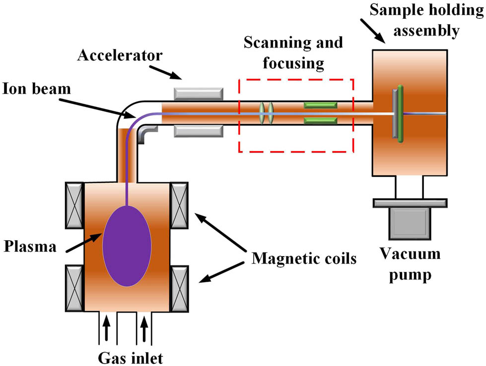
Experimental schematic of an ECR ion beam processing unit.
Experimental parameters of an ECR ion source for surface modification of EP insulation
| Parameters | Values |
|---|---|
| Flow rate of inlet gas (Ar) | 500 SCCM |
| Chamber vacuum pressure | 1.0–2.0 × 10⁻² Pa |
| Ion fluence | 6.5 × 10¹⁵ ions/cm2 |
| Injection energies | 6, 10, 20, 40, 50, and 60 keV |
| Treatment time | 300 s |
| Incident angle of the beam | 90° |
2.2 Experimental characterizations
An optical microscope named Leica-M165C was used to analyze the physical state/surface texture of the EPR insulation before and after the ion implantation. The images were captured and processed further for a better illustration. The surface topography and energy-dispersive X-ray (EDX) study was carried out through a scanning electron microscope to explore the irradiation effects of bombarded ions on the surface morphology and chemical composition of EP insulation. The unmodified and modified samples were sprayed with gold using an Emitech K550X coating device and an Edwards E2M2 high-vacuum pump for better scanning. The water absorption capability of EP insulation after irradiation by an ion beam was analyzed through the WCA test. First, a plastic syringe filled with demineralized water was used to drop 7 µL of water on the insulation surface. Next the water drop on the insulation surface was immediately captured through a camera fixed on a movable rail. Then, the obtained image of the drop was processed numerically through computer software to calculate the actual WCA. For experimental verification and to calculate the average value of WCA, the test was periodically repeated 15 times on various positions of the sample. The insulation samples were prepared without any bulk modification and therefore, we only measured surface conductivity (σ s) in this work. First, the insulation specimens were enclosed in a Keithley-8009 apparatus and a potential of 800 Vdc was supplied. Then, the polarization current was obtained periodically through an ampere meter in time steps of 30 s and recorded in a computer database. Finally, σ s for every insulation group were calculated by putting the values of current and voltages in the appropriate equation as described in the study by Du et al. [28]. In total, ten values are obtained for each sample to calculate the average of the results.
The isothermal surface potential decay (ISPD) method was employed to assess the surface potential characteristics of both unmodified and modified insulations [14,15]. Figure 3 illustrates the experimental setup for the ISPD test. A steel needle, featuring a 0.8 μm edge tip and 60 mm long, was suspended 15 mm above the insulator. A circular grid electrode with a 100 mm diameter was used for the homogenous distribution of charges on insulation. The insulator was placed on a grounded heater and the temperature was fixed at 30°C. Initially, the voltages were supplied to both needle and grid, raised and then fixed at ±12 and ±8 kV for 15 min. The voltages were removed after charging and a contactless voltage probe was used to scan the surface potential of the charged insulator for the scanning duration of 5 h. The measured data was obtained through an electrostatic voltmeter and then transferred to the computer via a data acquisition system for further processing. The humidity of the experiment was fixed at 30 ± 5% using a humidity-controlled box to obtain real results.
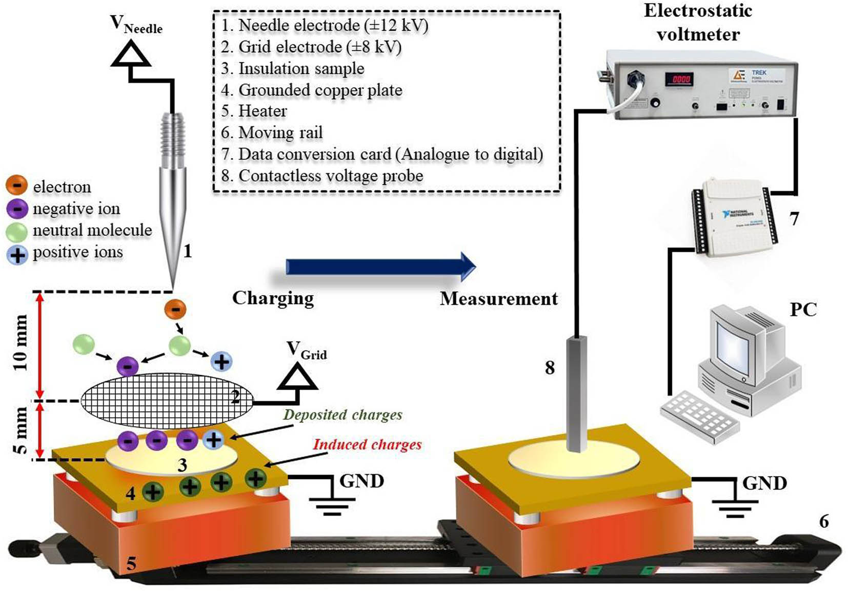
Experimental schematic of an ISPD setup.
The test apparatus for the flashover experiment is illustrated schematically in Figure 4(a). The insulation samples were tightened in between the finger electrodes made of steel with a gap distance of 10 mm and the test jig was fixed inside a temperature-controlled vacuum chamber. Next high voltages were applied across the electrodes using different polarities as shown in Figure 4(b) through a programmable HVDC source. The applied voltages were removed immediately just after the flashover and the data for flashover voltage and leakage current was recorded graphically on an oscilloscope (Tektronix TDS 2014B) using a current transformer and a high-voltage probe (Tektronix P6015A). After each subsequent test, the electrodes were cleaned using sandpaper and ethanol to avoid the effects of carbon on the results. The experiment was periodically repeated multiple times and the obtained data for the flashover test of each insulation was further processed numerically through Weibull statistical analysis to study the stability and reliability of the results. The experimental conditions are as follows: temperature (T = 30, 80, 120, 150°C); humidity (H = 30 ± 5%); vacuum pressure (P = 1.5 × 10⁻⁴ Pa); electrode gap (10 mm); electrode diameter (d electrode = 12.5 mm); sample thickness (a = 1 mm). A thermal imager and a high-speed camera were used to confirm the set temperature and to visualize the flashover occurrence, respectively.
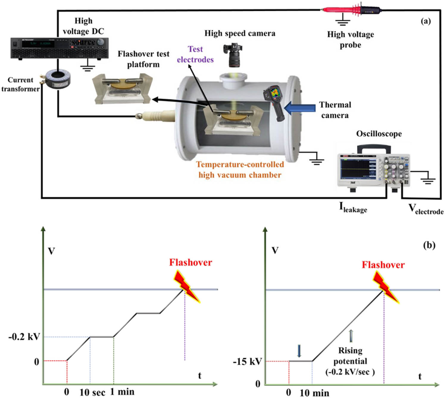
Experimental schematic of flashover (a) test platform and (b) voltage waveforms.
3 Results and discussion
3.1 Surface topography and chemical characterization
EP is a thermosetting polymer that may undergo physical changes after being exposed to ions of varying energies. The decline in the average molecular weight of the latter and the rise in local temperature of the EP surface due to the increase in ion energy causes structural defects in the material, known as color centers/oxygen vacancies [29], leading to the change in its density and optical properties [30]. Therefore, to confirm the modification of EP insulation by varied energy ion beams, here we reported the physical appearance of EP before and after modification. It is commonly known that pristine EP is an optically colorless and transparent polymer. However, from Figure 5, it can be observed that unmodified EP acquires a milky white color appearance. This is because a very small ratio of Al2/O3 particles was added to the pristine EP during the sample preparation process to enhance its mechanical strength. The color of the EP insulation changes from milky white to a light grey after bombardment with an ion beam of 6 keV. After that, the color of the EP insulation changes from metallic to dark black from sample M20 to M60. The appearance of the dark black color at high energy might be due to the elevated average band gap in the thermosetting conjugated polymer [29]. This different color appearance of the EP surface at different ion energies confirms the modification of the EP surface which may outcome in different electrical properties.
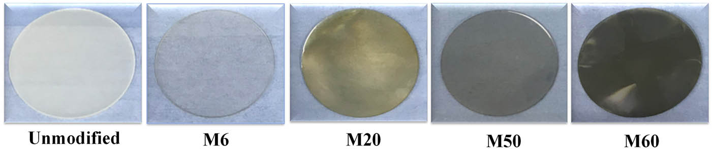
Surface color structure of unmodified and modified EP insulations under varied energy ion beams.
To further confirm the modification of EP insulation after bombardment with energetic ions, the surface topography of unmodified and modified insulations was obtained and compared through the SEM method. In this study, since only the surface of EP was modified, only the surface SEM was performed. From Figure 6, it can be observed that the surface of unmodified EP is very smooth. After modification with the ion beam of 60 keV, a large number of bumps appeared, apparently because of the physical sputtering effect of bombarded ions. These bumps may act as traps and can capture the surface charges in the deep surface of the insulation which can vary the surface flashover characteristics. The elemental composition of the unmodified and modified insulations was measured using the same SEM method and the results are presented in Figure 7. It is found that the amount of carbon elements has increased while the amount of oxygen elements has decreased considerably in the EP insulation after bombardment with the ion beam of 60 keV. In the presence of carbonyl groups and due to the increase in the local temperature of the EP, the irradiation damage caused by the bombarded ions might lead to the carbonization on EP surface which changes its surface color from milky white to dark black as already described in Figure 5. From this, we can say that the increase in carbon elements and change in the surface color of EP insulation confirms that the modification has been successfully applied.
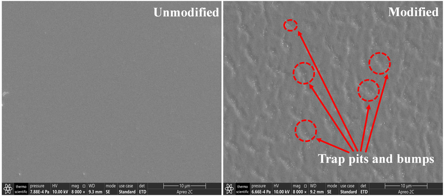
Surface topography of unmodified and modified (60 keV) EP insulation through SEM method.

Elemental composition of EP before and after modification (the modified sample is M60).
3.2 Flashover characteristics
As can be observed from Figure 4(b) (left), initially the negative DC voltages were applied to the flashover electrodes and raised through a programmable HVDC source at a rate of −0.2 kV/s. The electrodes were kept at this potential for 1 min and the voltages were raised again at the same rate. This cycle of applying voltage kept repeating and stopped immediately when a flashover and a spike in the leakage current were observed. In addition, due to the prolonged working operations of DC applications, e.g., power inverters/converters, the heating of electronic modules such as transistors could raise the temperature of the EP insulation which could also affect its flashover performance. Given this, the flashover tests were performed under varying temperatures, e.g., 30, 80, 120, and 150°C. A thermal imager (FOTRIC -325 pro) was used to analyze the temperature of the tested sample. Weibull distribution curves of experimental results were plotted and illustrated graphically in Figure 8. The test was repeated 20 times to obtain a mean value and to use it for Weibull analysis. The cumulative Weibull distribution function along with its detailed explanation can be found in our previous studies [26,27].
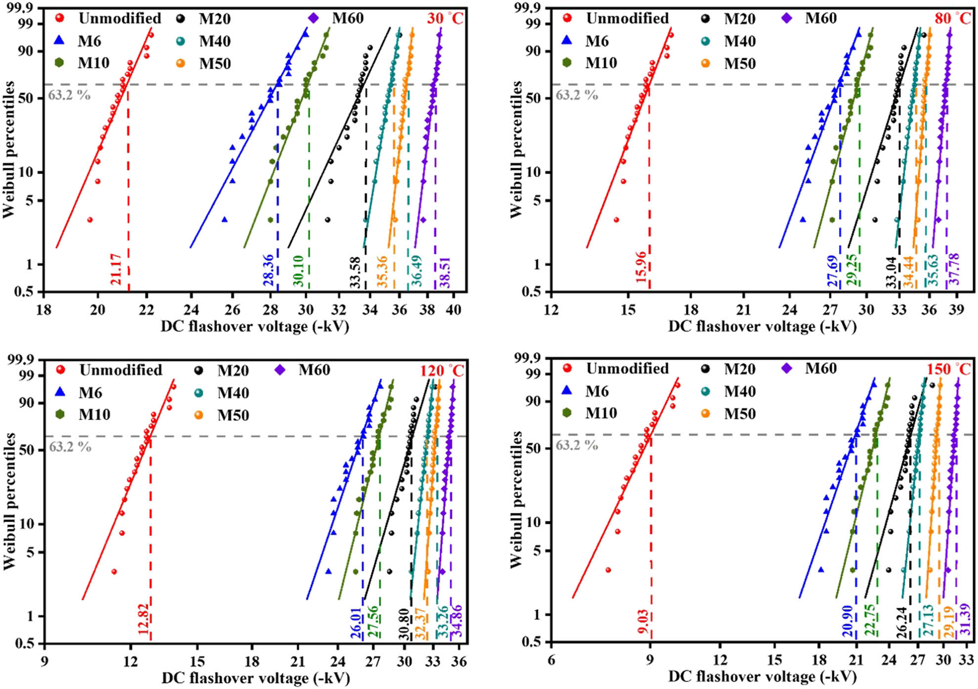
Flashover characteristics of unmodified and modified EP insulations under varying temperatures (considering applied voltage polarity as shown in Figure 4(b) (left)).
From Figure 8, it can be observed that flashover voltages (U flsh) of unmodified insulation are quite low compared to the modified one irrespective of the experimental temperature. Additionally, under any experimental temperature, the U flsh of the ion beam-modified insulations have raised significantly and increases with the increase in beam energy. The sample M60 modified by the beam of 60 keV attains the highest augmentation in U flsh. The U flsh of M60 improved by 45.02, 57.75, 63.22, and 71.23% under experimental temperatures of 30, 80, 120, and 150°C, respectively. Moreover, it can also be observed that the U flsh of unmodified insulations starts to drop dramatically with the increase in the experimental temperature, especially for the temperature of 150°C. However, the percentage of flashover voltage drop for modified insulations under varying temperatures is very low compared to the unmodified insulation. In light of this analysis, it can be claimed that after modification with an energetic ion beam, the EP insulation becomes thermally stable and shows much more improved flashover performances even at high temperatures.
It is commonly known that the accumulation degree of incoming charges usually depends upon the surface condition of polymer insulation, e.g., its surface conductivity, surface roughness, etc. [10,11]. Given this, to further explore the effects of ion bombardment on the surface charging of EP insulation, the samples were initially charged for 10 min under −15 kV using the needle-grid charging platform as shown in Figure 3. Figure 4(b) (right) shows the applied voltage waveform. After charging, the voltages at the electrodes were raised continuously at the rate of −0.2 kV/s and stopped immediately when a flashover was observed. The recorded data of U flsh was then processed numerically using Weibull statistical analysis and illustrated in Figure 9. From the results, it can be observed that U flsh of charged-unmodified insulations dropped dramatically compared to the uncharged-unmodified insulations and this ratio of voltage drop increases with the increases in sample temperature. This phenomenon of flashover voltage drop indicates the occurrence of a high amount of charge accumulation in unmodified EP insulation. Although the U flsh of charged-modified insulations also dropped compared to the U flsh of uncharged-modified insulations, the voltage drop ratio is quite low compared to the charged-unmodified insulations, indicating the effectiveness of ion beam modification. It can also be observed that among the modified insulations, the ratio of flashover voltage drop decreases with the rise in ion beam energy. The charged insulation sample M60 indicates the lowest flashover voltage drop among all the insulation samples irrespective of the applied temperature. To further explore the reasons for these different flashover characteristics, various characterizations are performed and the results are presented here.
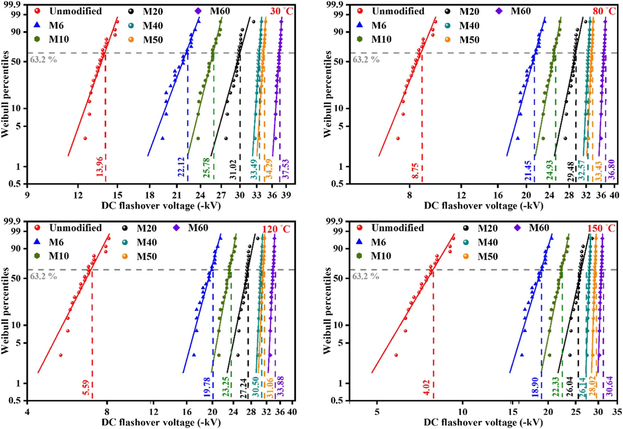
Flashover characteristics of unmodified and modified EP insulations under varying temperatures (considering applied voltage polarity as shown in Figure 4(b) (right)).
3.3 Surface conductivity measurement
It was observed from the already conducted research studies that surface conductivity (σ s) of polymer insulations had a great impact on flashover characteristics following their surface condition [14,16]. Therefore, in this section, σ s of unmodified and modified insulations are measured using a sealed 3-electrode system and the results are illustrated graphically as shown in Figure 10. The σ s of unmodified EP is quite high compared to the σ s of modified insulations. Also, it can be noticed that the σ s of modified EP decreases with the increase in energy of the ion beam. The σ s of the samples M6, M10, M20, M40, M50, and M60 decreases by 16.66, 36, 46.67, 66.8, 76, and 83.33%, respectively. The insulation sample M60 shows the highest decline in σ s among all the insulation samples. The above-presented results indicate that U flsh of EP insulation is strongly linked with its surface conductivity and improved with the decline in σ s after modification by the high-energy ion beam.
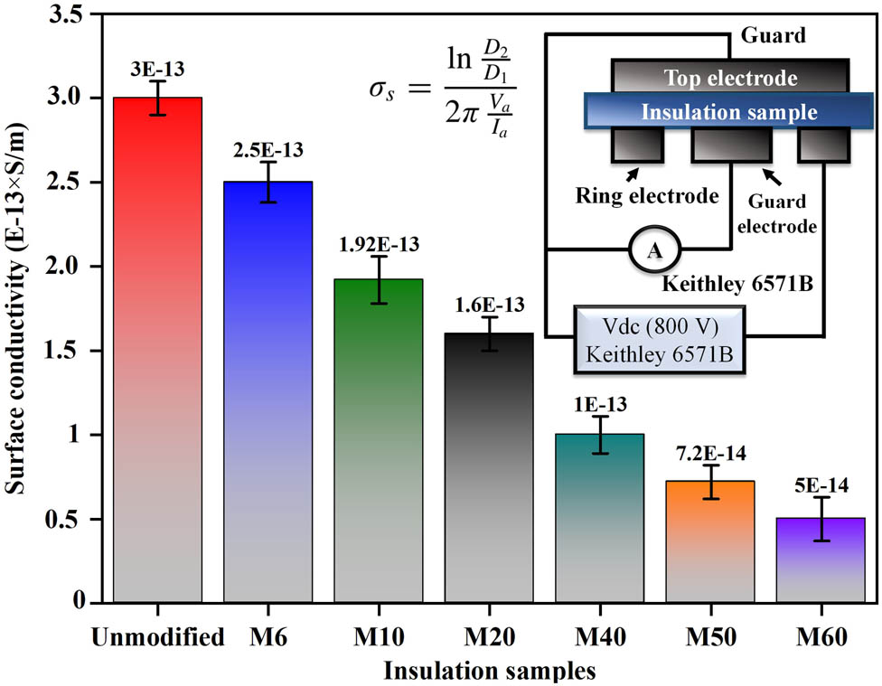
Surface conductivity of unmodified and modified insulations under varying ion beam energies.
The possible reasons for the decline in σ s after modification can be obtained from the surface wettability test. For this purpose, the WCA of unmodified and modified insulations is obtained through the experimental procedure as described earlier in the experimental section and computed via Young’s equation (1) [31,32].
where θ w is the WCA between the solid surface and water-vapor interface in degrees, Y SG is the surface tension of solid–gas, Y SL represents the surface tension of solid–liquid, and Y LG depicts the surface tension of liquid–gas.
From the results shown in Figure 11, it can be observed that the WCA of the unmodified sample is greater than 90° which indicates that it is hydrophobic according to the Young’s equation. After modification, the WCA of the EP insulation starts increasing and reaches to maximum for sample M60. This analysis shows that the bombardment of energetic ions with the EP surface only increases its hydrophobicity, which means that if unmodified EP is hydrophobic then ion bombardment can only enhance its hydrophobic nature, or if the unmodified EP is hydrophilic then ion bombardment can only enhance its hydrophilic nature. It was commonly known and proved from various studies that the rise in hydrophobicity of polymer insulation could decrease its surface conductivity [10,11]. Therefore, from the results of this study, it can be claimed that the increase in surface hydrophobicity of the EP insulation after ion bombardment is the major cause of decreasing its surface conductivity.
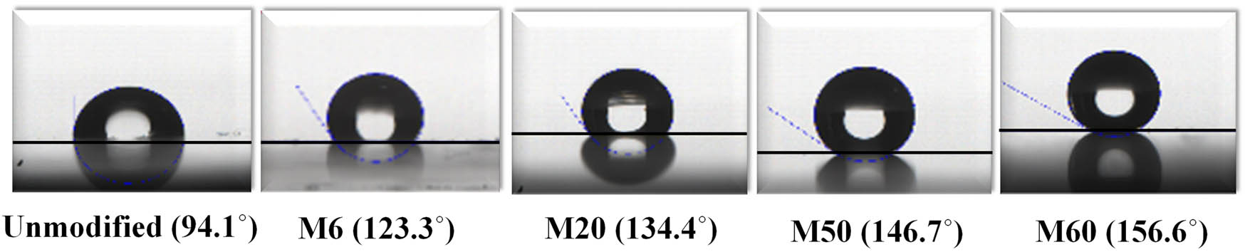
WCA measurement of unmodified and modified EP insulations.
3.4 Surface potential and surface trap characteristics
Previous studies indicate that surface charge characteristics of a polymer dielectric can be analyzed through its surface potential (U surf) which also has been considered as one of the critical parameters to characterize the flashover performance of a DC insulation system [33,34]. Therefore, in this section, to link the flashover voltages, surface charge characteristics, and surface conductivity, we measured the U surf performance of unmodified and modified insulations through the ISPD test described earlier in the experimental section. From the results shown in Figure 12, it can be observed that U surf of unmodified and modified insulations exponentially decays with time and reaches its lowest magnitude after a measurement time of 1,800 s. This exponential decay of U surf is because the incoming charges arrive at the insulation surface and are captured by the traps. With time, these captured charges decay slowly owing to the thermal effect (hoping mechanism). It can be seen that the initial surface potential (U int) of unmodified EP is −2.59 kV which drops to −1.159 kV (55.25%) after a measurement time of 1,800 s. On the other side, the U int of samples M6, M10, M20, M40, M50, and M60 drops to 35.31, 33.06, 28.50, 21.64, 20.17, and 17.30%, respectively. The above-presented quantitative analysis of surface potential indicates that modified EP insulation exhibits a quite slow decay compared to unmodified insulation due to the lower magnitude of σ s. The lower σ s reduces the movement of charges along the insulation surface and suppresses the decay of U surf.
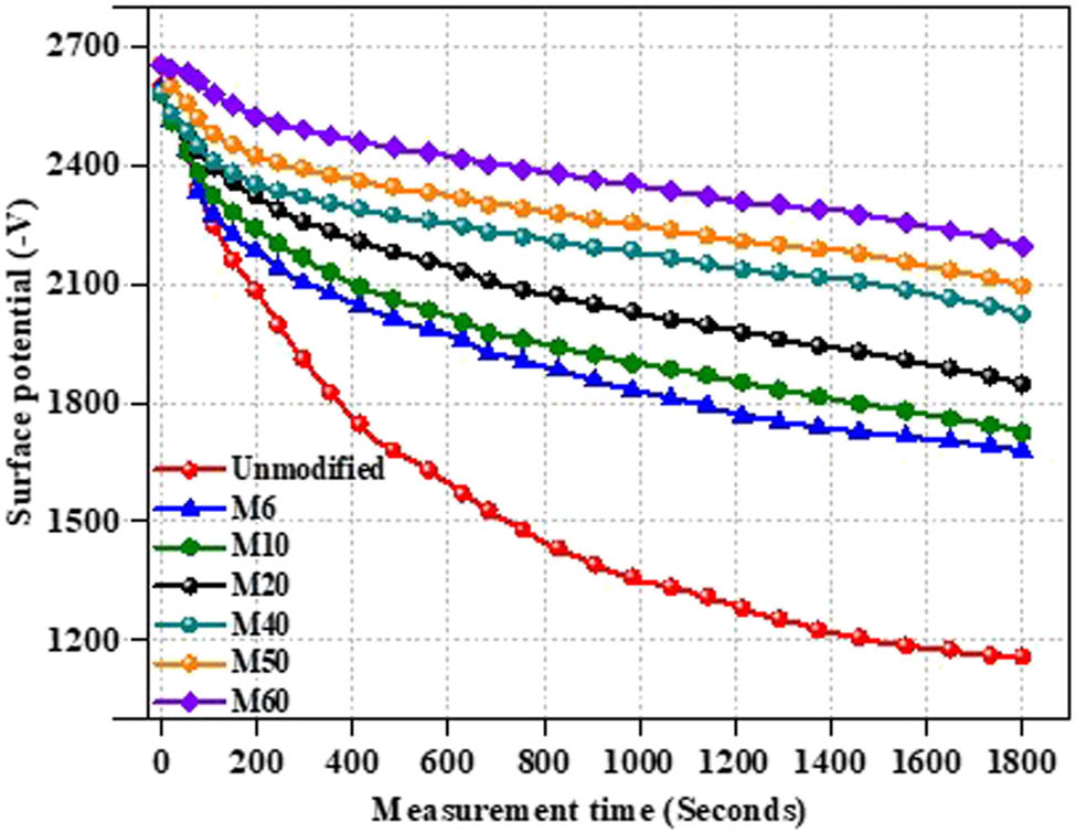
Surface potential measurement of unmodified and modified EP insulations.
To further explore the effects of ion bombardment on flashover characteristics, the trap parameters of EP insulation before and after modification were obtained using the following equations [14]:
where ε 0 is the dielectric constant for vacuum, ε r is the dielectric constant of the used material, dV s/d t is the decay rate of the surface potential, L is the thickness of the sample which is 1 mm in our study, q e is the unit charge in coulombs (1.6 × 10⁻¹⁹ C), k b is the Boltzmann’s constant, δ is the charge distribution range for even surface, T is the experimental temperature (298 K), and γ ATE is the carrier attempt-to-escape frequency.
From Figure 13, it can be observed that the surface trap curve has two peaks. The first peak belongs to the shallow traps while the second peak belongs to the deep traps. For unmodified EP, the energy (E T) and density (N(E T)) of shallow traps are quite high compared to the deep traps. After ion bombardment, the density of the shallow traps starts to decrease while the density of the deep traps starts to increase from samples M6 to M60. The sample M60 modified by the ion beam of the highest energy exhibits the highest density of deep traps and the lowest density of shallow traps. At the same time, after modification, from sample M6 to M60, the trap curve starts to move from the left to the right side. The enhanced density of deep traps, the declined density of shallow traps, and the movement of the trap curve from the left to the right side show that ion bombardment has introduced deeper traps in the EP surface. From previous studies [35,36,37], it was investigated that the introduction of deeper traps is the main reason for reducing the σ s and suppressing the surface potential decay. The reasons for the formation of deeper traps will be described in Section 5.
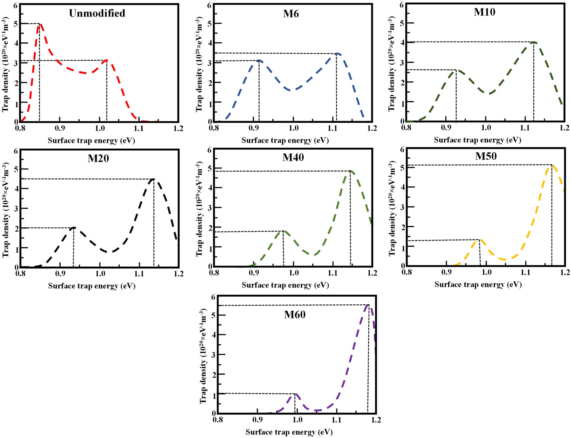
Trap distribution parameters of unmodified and modified EP insulations.
4 Discussion
The surface of EP insulation is considerably altered by bombarding the ions of varying energies to target the improved flashover characteristics for DC insulations. In this section, the detailed mechanism for flashover voltage improvement is explored through the SRIM program along with the experimental results and theoretical models. SRIM is a software program used to simulate the ions distribution and ions energy loss in the target material via Monte Carlo analyses. Monte Carlo is an analytical analysis method used for mathematical analysis [38]. Here we used SRIM to calculate the depth of ions in the EP insulation to find out the real reasons for deep trap formation. In this work, EP is used as a targeted material while Ar is used as a bombarded ion. The basic parameters for SRIM simulation are tabulated in Table 2 considering the resin, catalyst, hardener, and Ar ion source. According to the table values, the total molecular weight of carbon elements in the EP insulation should be equal to the total number of carbon elements in EPR (Bisphenol-A (C21H24O4)), hardener (MeTHPA (C9H10O3)), and catalyst (DMP-30 [(CH3)2NCH2]3C6H2OH). Similar calculations will be applied to the hydrogen, oxygen, and nitrogen elements. Considering this, the total molecular weight (MW) of the carbon elements is 540 amu, the total M. W of hydrogen elements is 61 amu, the total M. W of oxygen elements is 128 amu and the total MW of nitrogen elements is 42 amu in the targeted insulation. Similarly, the total density of the targeted insulation will be equal to the total density of EPR (1.2 g/cm3), hardener (1.21 g/cm3), and catalyst (0.96 g/cm3), which is 3.37 g/cm3 in this study. The energy of the incident Ar ions varies between 6 and 60 keV at an incident angle of 90°.
Simulation parameters of SRIM considering the EP as the target sample and Ar as the incident ion
| Bisphenol-A (C21H24O4) | MeTHPA (C9H10O3) | DMP-30 [(CH3)2NCH2]3C6H2OH | |||
|---|---|---|---|---|---|
| Atom | Molecular Wt (amu) | Atom | Molecular Wt (amu) | Atom | Molecular Wt (amu) |
| Carbon (C) | 21 × 12 = 252 | Carbon (C) | 9 × 12 = 108 | Carbon (C) | 6 × 12 + 3 × 12 + 6 × 12 = 180 |
| Hydrogen (H) | 24 × 1 = 24 | Hydrogen (H) | 10 × 1 = 10 | Hydrogen (H) | 18 × 1 + 6 × 1 + 2 × 1 + 1 × 1 = 27 |
| Oxygen (O) | 4 × 16 = 64 | Oxygen (O) | 3 × 16 = 48 | Oxygen (O) | 16 × 1 = 16 |
| Nitrogen (N) | 0 | Nitrogen (N) | 0 | Nitrogen (N) | 14 × 3 = 42 |
The radial and longitudinal range of incident ions in the targeted EP insulation is computed and illustrated graphically in Figure 14(a). The radial projection of the incident Ar ions in the targeted EP insulation lies between 10.17 and 65.70 nm while the longitudinal projection lies between 19.88 and 150.48 nm when the energy of the incident ions varies from 6 to 60 keV. With the rise in the ion energy, the disorder bounce of the bombarded ions will increase in both radial and longitudinal directions followed by the ion collision process. To further analyze the effects of bombarded ions on the insulation surface, the distribution of Ar ions in the depth direction is calculated and presented in Figure 14(b). It can be seen that the Ar ions are distributed to a certain depth below the surface of the EP insulation through a Gaussian distribution pattern. The process can be explained as follows. Initially, the incident ions with a specific energy continuously bombard the surface of the insulation, transferring their energy through electronic excitation or nuclear stopping [26,39], reaching inside the insulation to a certain depth below the surface, creating significant changes in the lattice layers, leaving vacancies due to the cascaded collision and then stop. These created vacancies will act as surface traps and can capture the surface charges. The depth of these vacancies/traps depends upon the energy of the bombarded ions. It can be observed that the distribution depth of the bombarded ions increases with the increase in ion energy which obviously will turn the surface traps into relatively deeper at higher ion energies. Hence, from Figure 14(a) and (b), it can be claimed that with the rise in energy of bombarded ions, the distribution depth of the ions inside the insulation surface also rises which causes the formation of the deeper surface traps. From the above-presented simulation results, the mechanism of the modification method on flashover voltage enhancement is explored as follows.
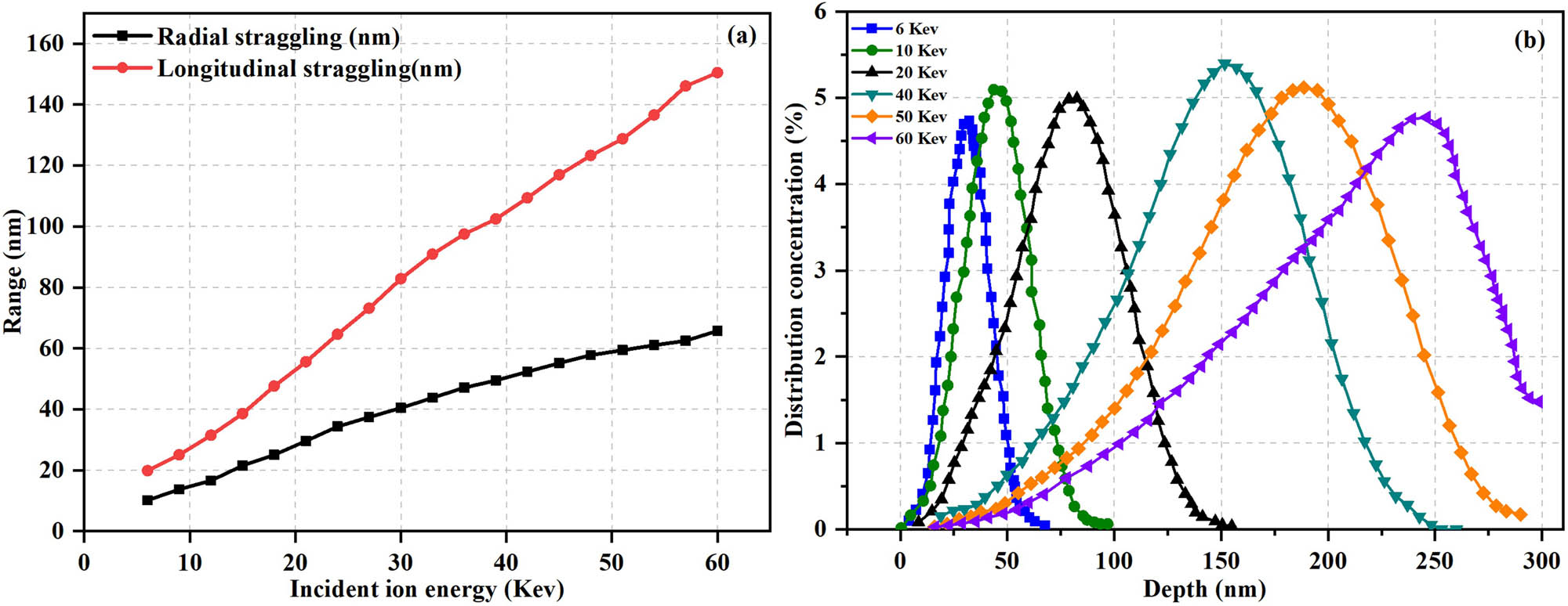
Range and depth distribution of incident ions in EP insulation. (a) Longitudinal straggling and radial straggling considering varying energy ions and (b) Ar+ ions distribution in depth considering varying energies.
The mechanism of air flashover can be explained through streamer theory [40,41] while for vacuum flashover, it follows the SEE avalanche model [34]. For unmodified insulation, the surface traps capture the incoming primary electrons at the point where flashover electrodes, solid insulation, and gas are close to each other and distort the E-field. Under periodic increases in applied voltages, the distortion of the E-field becomes high and emits more primary electrons. Some of the electrons are again captured by the traps and some will lead to the excitation of the secondary electrons. The continuous collision of the primary electrons with the insulation surface gives rise to the avalanche of secondary electrons which finally supports the flashover channel and reduces the U flsh.
After modification, it is observed from the experimental results that the bombarded ions alter the physical state of the insulation material by creating several pits and bumps under the sputtering effect. These physical pits act as surface traps and capture the surface charges. From the surface trap measurements, the density of the deep traps increases while the density of the shallow traps decreases with the increase in bombarded ion energy. Also, the trap curve shifted from the left to right direction with the rise in ion energy. Both these factors confirm the formation of deeper surface traps, assisting in a reduction in surface conductivity, confining the surface charge movements, and extensively suppressing the SEE yield [42,43]. Also, the enhanced trap depth induces homo-charge formation near triple junctions, declining the E-field distortion, and restricting the primary electron emission, synergistically, the factors contribute to high flashover voltages.
5 Conclusion
In this study, a novel modification method is employed to advance the surface of EP, resulting in a significant increase in flashover voltage. The experimental and simulation models validate the significance of the proposed approach, demonstrating its potential to advance the insulation characteristics of industrial applications effectively. The key findings are outlined below.
The surface color of the insulation sample was first changed from milky white to light grey from the unmodified sample to sample M6. After that, it changed from metallic to dark black when the energy of the incident ions varied between 20 and 60 keV. The appearance of the dark black color at high energy is due to the elevated average band gap in the thermosetting conjugated polymer which verifies that the modification has been applied to the insulation. The EDX analyses indicated that the content of the carbon elements in modified insulation had increased significantly which can lead to carbonization and therefore changed the color of the modified sample into a dark black tone. Moving forward, the surface topography of unmodified and modified insulation from SEM indicated that physical sputtering of ion bombardment induces electron bumps and pits which can capture the incoming charges and alter the surface charge characteristics of the insulation. To verify this statement, flashover voltages were measured under different temperatures and voltage polarities. The sample M60 modified by the beam of 60 keV attains the highest augmentation in U flsh. The U flsh of M60 improved by 45.02, 57.75, 63.22, and 71.23% under experimental temperatures of 30, 80, 120, and 150°C, respectively. Moreover, all the modified insulations showed a much more stable improvement of U flsh compared to the unmodified insulations at varying temperatures. Also, it was found that the effect of surface charge accumulation had reduced significantly in the modified insulation group. To justify the flashover voltage improvement and to explore the mechanism, various characterizations and numerical simulations were conducted. Simulation results revealed that energetic ions struck the surface of the insulation, created damage in the lattice layer, left vacancies, and then stopped to a certain depth far below the surface of the insulation. Due to these created vacancies, a large number of deep traps were formed in the modified insulations whose density increases with the increase in ion energy. The deep surface traps capture the incoming charges and do not let them de-trap. This phenomenon reduces the surface conductivity, suppressing the surface charge movements, and declining the SEE yield. Also, the enhanced trap depth induces homo-charge formation near triple junctions, declining the E-field distortion, and restricting the primary electron emission, synergistically, the factors contribute to high flashover voltages.
-
Funding information: This work was supported by the Natural Science Foundation of China (52250410350), and Researchers Supporting Project (RSP2024R492), King Saud University, Riyadh, Saudi Arabia.
-
Author contributions: Inzamam Ul Haq: conceptualization, writing – original draft preparation, and experimentations; Shakeel Akram: data curation and visualization; Zhi Fang: supervision and funding acquisition; Muhammad Tariq Nazir: investigation and proofreading; Essam A. Al-Ammar: methodology, software, and funding acquisition. All authors have accepted responsibility for the entire content of this manuscript and approved its submission.
-
Conflict of interest: The authors state no conflict of interest.
-
Data availability statement: The datasets generated and/or analyzed during the current study are available from the corresponding author on reasonable request.
References
[1] Awais M, Chen X, Dai C, Meng FB, Paramane A, Tanaka Y. Tuning epoxy for medium frequency transformer application: Resin optimization and characterization of nanocomposites at high temperature. IEEE Trans Dielectr Electr Insul. 2021 Oct;28(5):1751–8.10.1109/TDEI.2021.009596Search in Google Scholar
[2] Awais M, Chen X, Dai C, Wang Q, Meng FB, Hong Z, et al. Investigating optimal region for thermal and electrical properties of epoxy nanocomposites under high frequencies and temperatures. Nanotechnology. 2022 Jan;33(13):135705.10.1088/1361-6528/ac45c3Search in Google Scholar PubMed
[3] Ma GM, Zhou HY, Li CR, Jiang J, Chen XW. Designing epoxy insulators in SF6-filled DC-GIL with simulations of ionic conduction and surface charging. IEEE Trans Dielectr Electr Insul. 2015 Dec;22(6):3312–20.10.1109/TDEI.2015.005031Search in Google Scholar
[4] Jiang H, Xie Y, Zhu R, Luo Y, Sheng X, Xie D, et al. Construction of polyphosphazene-functionalized Ti3C2TX with high efficient flame retardancy for epoxy and its synergetic mechanisms. Chem Eng J. 2023 Jan;456:141049.10.1016/j.cej.2022.141049Search in Google Scholar
[5] Jiang Y, Liu L, Yan J, Wu Z. Room-to-low temperature thermo-mechanical behavior and corresponding constitutive model of liquid oxygen compatible epoxy composites. Compos Sci Technol. 2024 Jan;245:110357.10.1016/j.compscitech.2023.110357Search in Google Scholar
[6] Pang B, Jin Z, Zhang Y, Xu L, Li M, Wang C, et al. Ultraductile waterborne epoxy-concrete composite repair material: Epoxy-fiber synergistic effect on flexural and tensile performance. Cem Concr Compos. 2022 May;129:104463.10.1016/j.cemconcomp.2022.104463Search in Google Scholar
[7] Gao Y, Li Z, Wang H, Yuan X. Metal particle encouraged surface charge accumulation on epoxy insulator with multi-arc surface profile under DC voltage. IEEE Trans Dielectr Electr Insul. 2020 May;27(3):998–1006.10.1109/TDEI.2019.008634Search in Google Scholar
[8] Huang J, Zhu Y, Guo S, Guo L, Yu W, Akram S, et al. Surface treatment of large-area epoxy resin by water-perforated metal plate electrodes dielectric barrier discharge: Hydrophobic modification and uniformity improvement. Appl Surf Sci. 2023 Dec;639:158166.10.1016/j.apsusc.2023.158166Search in Google Scholar
[9] Du B, Du Q, Li J, Liang H. Carrier mobility and trap distribution dependent flashover characteristics of epoxy resin. IET Gener Transm Dis. 2018 Jan;12(2):466–71.10.1049/iet-gtd.2017.0984Search in Google Scholar
[10] Zhang Z, Wang Z, Teyssedre G, Shahsavarian T, Baferani MA, Chen G, et al. Gas–solid interface charge tailoring techniques: what we grasped and where to go. Nanotechnology. 2020 Dec;32(12):122001.10.1088/1361-6528/abcceaSearch in Google Scholar PubMed
[11] Zhu M, Xue J, Wei Y, Li G, Zhang G. Review of interface tailoring techniques and applications to improve insulation performance. High Volt. 2022 Feb;7(1):12–31.10.1049/hve2.12094Search in Google Scholar
[12] Wang T, Zhang G, Li D, Hou Y, Zhang B. MXene-doped epoxy resin to suppress surface charge accumulation on insulators in a DC gas-insulated system. IEEE Trans Dielectr Electr Insul. 2020 May;27(3):939–46.10.1109/TDEI.2019.008527Search in Google Scholar
[13] Wang F, Zhang T, Li J, Zeeshan KM, He L, Huang Z, et al. DC breakdown and flashover characteristics of direct fluorinated epoxy/Al2O3 nanocomposites. IEEE Trans Dielectr Electr Insul. 2019 May;26(3):702–37.10.1109/TDEI.2019.8726018Search in Google Scholar
[14] Chen X, Chen S, Zhang B, Li G, Chang Z, Zhang GJ. Promotion of epoxy resin surface electrical insulation performance and its stability by atmospheric fluorocarbon dielectric barrier discharge. IEEE Trans Dielectr Electr Insul. 2020 Dec;27(6):1973–81.10.1109/TDEI.2020.008777Search in Google Scholar
[15] Chen X, Guan H, Jiang T, Du H, Paramane A, Zhou H. Surface charge dissipation and DC flashover characteristic of DBD plasma treated epoxy resin/AlN nanocomposites. IEEE Trans Dielectr Electr Insul. 2020 Apr;27(2):504–11. 10.1109/TDEI.2019.008598.Search in Google Scholar
[16] Shao T, Liu F, Hai B, Ma Y, Wang R, Ren C. Surface modification of epoxy using an atmospheric pressure dielectric barrier discharge to accelerate surface charge dissipation. IEEE Trans Dielectr Electr Insul. 2017;24(3):1557–65.10.1109/TDEI.2017.006321Search in Google Scholar
[17] Huang Y, Xue J, Wang T, Liu C, Li D, Hou Y, et al. Surface flashover performance of epoxy resin micro composites improved by electron beam irradiation. Appl Surf Sci. 2017 Jun;406:39–45.10.1016/j.apsusc.2017.02.093Search in Google Scholar
[18] Xue J, Wang T, Liu C, Li D, Hou Y, Zhang G, et al. Surface charge transport behavior and flashover mechanism on alumina/epoxy spacers coated by SiC/epoxy composites with varied SiC particle size. J Phys D: Appl Phys. 2020 Apr;53(15):155503.10.1088/1361-6463/ab6d1aSearch in Google Scholar
[19] Wang T, Liu C, Li D, Hou Y, Zhang G, Zhang B. Nano ZnO/epoxy coating to promote surface charge dissipation on insulators in DC gas-insulated systems. IEEE Trans Dielectr Electr Insul. 2020 Aug;27(4):1322–9.10.1109/TDEI.2020.008793Search in Google Scholar
[20] Liang C, Turos A, Jagielski J, Rutkowski A, Bieliński D, Ślusarski L, et al. Remarkable modification of transferring characteristics for both positive and negative charges in XLPE-PS composite. Compos Commun. 2023;40:101587.10.1016/j.coco.2023.101587Search in Google Scholar
[21] Ru J, Min D, Ma B, Pan S, Xing Z, Li S. Influence of surface trap parameters on DC flashover in vacuum of epoxy composites. IEEE 2016 International Conference on Condition Monitoring and Diagnosis (CMD); 2016. p. 1008–11.10.1109/CMD.2016.7757997Search in Google Scholar
[22] Yu S, Li S. The relationship between surface flashover properties and trap characteristics of nanocomposites. IEEE 2016 International Conference on Condition Monitoring and Diagnosis (CMD); 2016. p. 960–3.10.1109/CMD.2016.7757984Search in Google Scholar
[23] Zhao W, Xu R, Ren C, Wang J, Yan P. Ion-implantation modification of surface flashover properties in vacuum of polytetrafluoroethylene. IEEE Trans Plasma Sci. 2018 Oct;46(10):3450–6.10.1109/TPS.2018.2819987Search in Google Scholar
[24] Turos A, Jagielski J, Rutkowski A, Bieliński D, Ślusarski L, Madi NK. Ion beam modification of surface properties of polyethylene. Vacuum. 2003;70(2-3):201–6.10.1016/S0042-207X(02)00643-7Search in Google Scholar
[25] Nowak P, McIntyre NS, Hunter DH, Bello I, Lau WM. Addition of a single chemical functional group to a polymer surface with a mass-separated low-energy ion beam. Surf Interface Anal. 1995;23(13):873–8.10.1002/sia.740231304Search in Google Scholar
[26] Haq IU, Wang F, Akram S, Yan Y. Effects of ion beam treatment on DC flashover characteristics of epoxy. IEEE Trans Dielectr Electr Insul. 2022;29(6):2064–71.10.1109/TDEI.2022.3212973Search in Google Scholar
[27] Haq IU, Wang F, Akram S, Yan Y. Improved flashover characteristics of surface modified epoxy by ion beam treatment. IEEE 4th International Conference on Dielectrics (ICD); 2022. p. 478–81.10.1109/ICD53806.2022.9863603Search in Google Scholar
[28] Du BX, Ran ZY, Li J, Liang HC. Novel insulator with interfacial σ-FGM for DC compact gaseous insulated pipeline. IEEE Trans Dielectr Electr Insul. 2019 Jun;26(3):818–25.10.1109/TDEI.2019.007778Search in Google Scholar
[29] EL-Muraikhi M. Ion radiation detection using implanted ultrahigh molecular weight polyethylene structures (UHMWPE). Mater Sci Appl. 2018;10(1):12–24.10.4236/msa.2019.101002Search in Google Scholar
[30] Teyssedre G, Laurent C. Charge transport modeling in insulating polymers: from molecular to macroscopic scale. IEEE Trans Dielectr Electr Insul. 2005;12(5):857–75.10.1109/TDEI.2005.1522182Search in Google Scholar
[31] Adam NK. Use of the term ‘Young’s Equation’ for contact angles. Nature. 1957;180(4590):809–10.10.1038/180809a0Search in Google Scholar
[32] Bormashenko E. Physics of solid–liquid interfaces: From the Young equation to the superhydrophobicity. Low Temp Phys. 2016;42(8):622–35.10.1063/1.4960495Search in Google Scholar
[33] Li Z, Min D, Niu H, Li M, Li S. Simulation of DC surface flashover of epoxy composites in compressed nitrogen. Appl Phys. 2021 Aug;130(5):053301.10.1063/5.0059594Search in Google Scholar
[34] Li S. Improvement of surface flashover in vacuum. High Volt. 2020 Apr;5(2):122–33.10.1049/hve.2020.0021Search in Google Scholar
[35] Lee EH, Rao GR, Lewis MB. Effects of electronic and recoil processes in polymers during ion implantation. Mater Res. 1994;9(4):1043–50.10.1557/JMR.1994.1043Search in Google Scholar
[36] Pan S, Wang X, Min D, Li D, Rao X, Su Y, et al. Effect of deposited charge on vacuum DC surface flashover under electron beam irradiation. IEEE Trans Plasma Sci. 2022 May;50(6):1934–41.10.1109/TPS.2022.3174607Search in Google Scholar
[37] Ahmed M, Zhong L, Li F, Xu N, Gao J. Improving the DC dielectric properties of XLPE with appropriate content of dicumyl peroxide for HVDC cables insulation. Materials. 2022;15(17):5857.10.3390/ma15175857Search in Google Scholar PubMed PubMed Central
[38] Zhihui L, Meng X, Lin L, Li H, Chen Y, Mei H. Impact of nano-Al2O3 coating on the dielectric properties and high-frequency surface electrical strength of the polyimide films. Appl Surf Sci. 2023;634:157666.10.1016/j.apsusc.2023.157666Search in Google Scholar
[39] Meng X, Lin L, Li H, Chen Y, Mei H. Characteristics of streamer discharge along the insulation surface with embedded electrode. IEEE Trans Dielectr Electr Insul. 2024;31:2038–44. 10.1109/TDEI.2024.3394833.Search in Google Scholar
[40] Meng X, Zhang B, Cao F, Liao Y. Effectiveness of measures on natural gas pipelines for mitigating the influence of DC ground current. IEEE Trans Power Delivery. 2024;39:2414–23. 10.1109/TPWRD.2024.3406826.Search in Google Scholar
[41] Liu Y, Liu X, Li X, Yuan H. Analytical model and safe-operation-area analysis of bridge-leg crosstalk of GaN E-HEMT considering correlation effect of multi-parameters. IEEE Trans Power Electron. 2024;39(7):8146–61. 10.1109/TPEL.2024.3381638.Search in Google Scholar
[42] Zhu Q, Chen J, Gou G, Chen H, Li P. Ameliorated longitudinal critically refracted—attenuation velocity method for welding residual stress measurement. J Mater Process Technol. 2017;246:267–75. 10.1016/j.jmatprotec.2017.03.022.Search in Google Scholar
[43] Ju Y, Liu W, Zhang Z, Zhang R. Distributed three-phase power flow for AC/DC hybrid networked microgrids considering converter limiting constraints. IEEE Trans Smart Grid. 2022;13(3):1691–708. 10.1109/TSG.2022.3140212.Search in Google Scholar
© 2024 the author(s), published by De Gruyter
This work is licensed under the Creative Commons Attribution 4.0 International License.
Articles in the same Issue
- Research Articles
- Tension buckling and postbuckling of nanocomposite laminated plates with in-plane negative Poisson’s ratio
- Polyvinylpyrrolidone-stabilised gold nanoparticle coatings inhibit blood protein adsorption
- Energy and mass transmission through hybrid nanofluid flow passing over a spinning sphere with magnetic effect and heat source/sink
- Surface treatment with nano-silica and magnesium potassium phosphate cement co-action for enhancing recycled aggregate concrete
- Numerical investigation of thermal radiation with entropy generation effects in hybrid nanofluid flow over a shrinking/stretching sheet
- Enhancing the performance of thermal energy storage by adding nano-particles with paraffin phase change materials
- Using nano-CaCO3 and ceramic tile waste to design low-carbon ultra high performance concrete
- Numerical analysis of thermophoretic particle deposition in a magneto-Marangoni convective dusty tangent hyperbolic nanofluid flow – Thermal and magnetic features
- Dual numerical solutions of Casson SA–hybrid nanofluid toward a stagnation point flow over stretching/shrinking cylinder
- Single flake homo p–n diode of MoTe2 enabled by oxygen plasma doping
- Electrostatic self-assembly effect of Fe3O4 nanoparticles on performance of carbon nanotubes in cement-based materials
- Multi-scale alignment to buried atom-scale devices using Kelvin probe force microscopy
- Antibacterial, mechanical, and dielectric properties of hydroxyapatite cordierite/zirconia porous nanocomposites for use in bone tissue engineering applications
- Time-dependent Darcy–Forchheimer flow of Casson hybrid nanofluid comprising the CNTs through a Riga plate with nonlinear thermal radiation and viscous dissipation
- Durability prediction of geopolymer mortar reinforced with nanoparticles and PVA fiber using particle swarm optimized BP neural network
- Utilization of zein nano-based system for promoting antibiofilm and anti-virulence activities of curcumin against Pseudomonas aeruginosa
- Antibacterial effect of novel dental resin composites containing rod-like zinc oxide
- An extended model to assess Jeffery–Hamel blood flow through arteries with iron-oxide (Fe2O3) nanoparticles and melting effects: Entropy optimization analysis
- Comparative study of copper nanoparticles over radially stretching sheet with water and silicone oil
- Cementitious composites modified by nanocarbon fillers with cooperation effect possessing excellent self-sensing properties
- Confinement size effect on dielectric properties, antimicrobial activity, and recycling of TiO2 quantum dots via photodegradation processes of Congo red dye and real industrial textile wastewater
- Biogenic silver nanoparticles of Moringa oleifera leaf extract: Characterization and photocatalytic application
- Novel integrated structure and function of Mg–Gd neutron shielding materials
- Impact of multiple slips on thermally radiative peristaltic transport of Sisko nanofluid with double diffusion convection, viscous dissipation, and induced magnetic field
- Magnetized water-based hybrid nanofluid flow over an exponentially stretching sheet with thermal convective and mass flux conditions: HAM solution
- A numerical investigation of the two-dimensional magnetohydrodynamic water-based hybrid nanofluid flow composed of Fe3O4 and Au nanoparticles over a heated surface
- Development and modeling of an ultra-robust TPU-MWCNT foam with high flexibility and compressibility
- Effects of nanofillers on the physical, mechanical, and tribological behavior of carbon/kenaf fiber–reinforced phenolic composites
- Polymer nanocomposite for protecting photovoltaic cells from solar ultraviolet in space
- Study on the mechanical properties and microstructure of recycled concrete reinforced with basalt fibers and nano-silica in early low-temperature environments
- Synergistic effect of carbon nanotubes and polyvinyl alcohol on the mechanical performance and microstructure of cement mortar
- CFD analysis of paraffin-based hybrid (Co–Au) and trihybrid (Co–Au–ZrO2) nanofluid flow through a porous medium
- Forced convective tangent hyperbolic nanofluid flow subject to heat source/sink and Lorentz force over a permeable wedge: Numerical exploration
- Physiochemical and electrical activities of nano copper oxides synthesised via hydrothermal method utilising natural reduction agents for solar cell application
- A homotopic analysis of the blood-based bioconvection Carreau–Yasuda hybrid nanofluid flow over a stretching sheet with convective conditions
- In situ synthesis of reduced graphene oxide/SnIn4S8 nanocomposites with enhanced photocatalytic performance for pollutant degradation
- A coarse-grained Poisson–Nernst–Planck model for polyelectrolyte-modified nanofluidic diodes
- A numerical investigation of the magnetized water-based hybrid nanofluid flow over an extending sheet with a convective condition: Active and passive controls of nanoparticles
- The LyP-1 cyclic peptide modified mesoporous polydopamine nanospheres for targeted delivery of triptolide regulate the macrophage repolarization in atherosclerosis
- Synergistic effect of hydroxyapatite-magnetite nanocomposites in magnetic hyperthermia for bone cancer treatment
- The significance of quadratic thermal radiative scrutinization of a nanofluid flow across a microchannel with thermophoretic particle deposition effects
- Ferromagnetic effect on Casson nanofluid flow and transport phenomena across a bi-directional Riga sensor device: Darcy–Forchheimer model
- Performance of carbon nanomaterials incorporated with concrete exposed to high temperature
- Multicriteria-based optimization of roller compacted concrete pavement containing crumb rubber and nano-silica
- Revisiting hydrotalcite synthesis: Efficient combined mechanochemical/coprecipitation synthesis to design advanced tunable basic catalysts
- Exploration of irreversibility process and thermal energy of a tetra hybrid radiative binary nanofluid focusing on solar implementations
- Effect of graphene oxide on the properties of ternary limestone clay cement paste
- Improved mechanical properties of graphene-modified basalt fibre–epoxy composites
- Sodium titanate nanostructured modified by green synthesis of iron oxide for highly efficient photodegradation of dye contaminants
- Green synthesis of Vitis vinifera extract-appended magnesium oxide NPs for biomedical applications
- Differential study on the thermal–physical properties of metal and its oxide nanoparticle-formed nanofluids: Molecular dynamics simulation investigation of argon-based nanofluids
- Heat convection and irreversibility of magneto-micropolar hybrid nanofluids within a porous hexagonal-shaped enclosure having heated obstacle
- Numerical simulation and optimization of biological nanocomposite system for enhanced oil recovery
- Laser ablation and chemical vapor deposition to prepare a nanostructured PPy layer on the Ti surface
- Cilostazol niosomes-loaded transdermal gels: An in vitro and in vivo anti-aggregant and skin permeation activity investigations towards preparing an efficient nanoscale formulation
- Linear and nonlinear optical studies on successfully mixed vanadium oxide and zinc oxide nanoparticles synthesized by sol–gel technique
- Analytical investigation of convective phenomena with nonlinearity characteristics in nanostratified liquid film above an inclined extended sheet
- Optimization method for low-velocity impact identification in nanocomposite using genetic algorithm
- Analyzing the 3D-MHD flow of a sodium alginate-based nanofluid flow containing alumina nanoparticles over a bi-directional extending sheet using variable porous medium and slip conditions
- A comprehensive study of laser irradiated hydrothermally synthesized 2D layered heterostructure V2O5(1−x)MoS2(x) (X = 1–5%) nanocomposites for photocatalytic application
- Computational analysis of water-based silver, copper, and alumina hybrid nanoparticles over a stretchable sheet embedded in a porous medium with thermophoretic particle deposition effects
- A deep dive into AI integration and advanced nanobiosensor technologies for enhanced bacterial infection monitoring
- Effects of normal strain on pyramidal I and II 〈c + a〉 screw dislocation mobility and structure in single-crystal magnesium
- Computational study of cross-flow in entropy-optimized nanofluids
- Significance of nanoparticle aggregation for thermal transport over magnetized sensor surface
- A green and facile synthesis route of nanosize cupric oxide at room temperature
- Effect of annealing time on bending performance and microstructure of C19400 alloy strip
- Chitosan-based Mupirocin and Alkanna tinctoria extract nanoparticles for the management of burn wound: In vitro and in vivo characterization
- Electrospinning of MNZ/PLGA/SF nanofibers for periodontitis
- Photocatalytic degradation of methylene blue by Nd-doped titanium dioxide thin films
- Shell-core-structured electrospinning film with sequential anti-inflammatory and pro-neurogenic effects for peripheral nerve repairment
- Flow and heat transfer insights into a chemically reactive micropolar Williamson ternary hybrid nanofluid with cross-diffusion theory
- One-pot fabrication of open-spherical shapes based on the decoration of copper sulfide/poly-O-amino benzenethiol on copper oxide as a promising photocathode for hydrogen generation from the natural source of Red Sea water
- A penta-hybrid approach for modeling the nanofluid flow in a spatially dependent magnetic field
- Advancing sustainable agriculture: Metal-doped urea–hydroxyapatite hybrid nanofertilizer for agro-industry
- Utilizing Ziziphus spina-christi for eco-friendly synthesis of silver nanoparticles: Antimicrobial activity and promising application in wound healing
- Plant-mediated synthesis, characterization, and evaluation of a copper oxide/silicon dioxide nanocomposite by an antimicrobial study
- Effects of PVA fibers and nano-SiO2 on rheological properties of geopolymer mortar
- Investigating silver and alumina nanoparticles’ impact on fluid behavior over porous stretching surface
- Potential pharmaceutical applications and molecular docking study for green fabricated ZnO nanoparticles mediated Raphanus sativus: In vitro and in vivo study
- Effect of temperature and nanoparticle size on the interfacial layer thickness of TiO2–water nanofluids using molecular dynamics
- Characteristics of induced magnetic field on the time-dependent MHD nanofluid flow through parallel plates
- Flexural and vibration behaviours of novel covered CFRP composite joints with an MWCNT-modified adhesive
- Experimental research on mechanically and thermally activation of nano-kaolin to improve the properties of ultra-high-performance fiber-reinforced concrete
- Analysis of variable fluid properties for three-dimensional flow of ternary hybrid nanofluid on a stretching sheet with MHD effects
- Biodegradability of corn starch films containing nanocellulose fiber and thymol
- Toxicity assessment of copper oxide nanoparticles: In vivo study
- Some measures to enhance the energy output performances of triboelectric nanogenerators
- Reinforcement of graphene nanoplatelets on water uptake and thermomechanical behaviour of epoxy adhesive subjected to water ageing conditions
- Optimization of preparation parameters and testing verification of carbon nanotube suspensions used in concrete
- Max-phase Ti3SiC2 and diverse nanoparticle reinforcements for enhancement of the mechanical, dynamic, and microstructural properties of AA5083 aluminum alloy via FSP
- Advancing drug delivery: Neural network perspectives on nanoparticle-mediated treatments for cancerous tissues
- PEG-PLGA core–shell nanoparticles for the controlled delivery of picoplatin–hydroxypropyl β-cyclodextrin inclusion complex in triple-negative breast cancer: In vitro and in vivo study
- Conduction transportation from graphene to an insulative polymer medium: A novel approach for the conductivity of nanocomposites
- Review Articles
- Developments of terahertz metasurface biosensors: A literature review
- Overview of amorphous carbon memristor device, modeling, and applications for neuromorphic computing
- Advances in the synthesis of gold nanoclusters (AuNCs) of proteins extracted from nature
- A review of ternary polymer nanocomposites containing clay and calcium carbonate and their biomedical applications
- Recent advancements in polyoxometalate-functionalized fiber materials: A review
- Special contribution of atomic force microscopy in cell death research
- A comprehensive review of oral chitosan drug delivery systems: Applications for oral insulin delivery
- Cellular senescence and nanoparticle-based therapies: Current developments and perspectives
- Cyclodextrins-block copolymer drug delivery systems: From design and development to preclinical studies
- Micelle-based nanoparticles with stimuli-responsive properties for drug delivery
- Critical assessment of the thermal stability and degradation of chemically functionalized nanocellulose-based polymer nanocomposites
- Research progress in preparation technology of micro and nano titanium alloy powder
- Nanoformulations for lysozyme-based additives in animal feed: An alternative to fight antibiotic resistance spread
- Incorporation of organic photochromic molecules in mesoporous silica materials: Synthesis and applications
- A review on modeling of graphene and associated nanostructures reinforced concrete
- A review on strengthening mechanisms of carbon quantum dots-reinforced Cu-matrix nanocomposites
- Review on nanocellulose composites and CNFs assembled microfiber toward automotive applications
- Nanomaterial coating for layered lithium rich transition metal oxide cathode for lithium-ion battery
- Application of AgNPs in biomedicine: An overview and current trends
- Nanobiotechnology and microbial influence on cold adaptation in plants
- Hepatotoxicity of nanomaterials: From mechanism to therapeutic strategy
- Applications of micro-nanobubble and its influence on concrete properties: An in-depth review
- A comprehensive systematic literature review of ML in nanotechnology for sustainable development
- Exploiting the nanotechnological approaches for traditional Chinese medicine in childhood rhinitis: A review of future perspectives
- Twisto-photonics in two-dimensional materials: A comprehensive review
- Current advances of anticancer drugs based on solubilization technology
- Recent process of using nanoparticles in the T cell-based immunometabolic therapy
- Future prospects of gold nanoclusters in hydrogen storage systems and sustainable environmental treatment applications
- Preparation, types, and applications of one- and two-dimensional nanochannels and their transport properties for water and ions
- Microstructural, mechanical, and corrosion characteristics of Mg–Gd–x systems: A review of recent advancements
- Functionalized nanostructures and targeted delivery systems with a focus on plant-derived natural agents for COVID-19 therapy: A review and outlook
- Mapping evolution and trends of cell membrane-coated nanoparticles: A bibliometric analysis and scoping review
- Nanoparticles and their application in the diagnosis of hepatocellular carcinoma
- In situ growth of carbon nanotubes on fly ash substrates
- Structural performance of boards through nanoparticle reinforcement: An advance review
- Reinforcing mechanisms review of the graphene oxide on cement composites
- Seed regeneration aided by nanomaterials in a climate change scenario: A comprehensive review
- Surface-engineered quantum dot nanocomposites for neurodegenerative disorder remediation and avenue for neuroimaging
- Graphitic carbon nitride hybrid thin films for energy conversion: A mini-review on defect activation with different materials
- Nanoparticles and the treatment of hepatocellular carcinoma
- Special Issue on Advanced Nanomaterials and Composites for Energy Conversion and Storage - Part II
- Highly safe lithium vanadium oxide anode for fast-charging dendrite-free lithium-ion batteries
- Recent progress in nanomaterials of battery energy storage: A patent landscape analysis, technology updates, and future prospects
- Special Issue on Advanced Nanomaterials for Carbon Capture, Environment and Utilization for Energy Sustainability - Part II
- Calcium-, magnesium-, and yttrium-doped lithium nickel phosphate nanomaterials as high-performance catalysts for electrochemical water oxidation reaction
- Low alkaline vegetation concrete with silica fume and nano-fly ash composites to improve the planting properties and soil ecology
- Mesoporous silica-grafted deep eutectic solvent-based mixed matrix membranes for wastewater treatment: Synthesis and emerging pollutant removal performance
- Electrochemically prepared ultrathin two-dimensional graphitic nanosheets as cathodes for advanced Zn-based energy storage devices
- Enhanced catalytic degradation of amoxicillin by phyto-mediated synthesised ZnO NPs and ZnO-rGO hybrid nanocomposite: Assessment of antioxidant activity, adsorption, and thermodynamic analysis
- Incorporating GO in PI matrix to advance nanocomposite coating: An enhancing strategy to prevent corrosion
- Synthesis, characterization, thermal stability, and application of microporous hyper cross-linked polyphosphazenes with naphthylamine group for CO2 uptake
- Engineering in ceramic albite morphology by the addition of additives: Carbon nanotubes and graphene oxide for energy applications
- Nanoscale synergy: Optimizing energy storage with SnO2 quantum dots on ZnO hexagonal prisms for advanced supercapacitors
- Aging assessment of silicone rubber materials under corona discharge accompanied by humidity and UV radiation
- Tuning structural and electrical properties of Co-precipitated and Cu-incorporated nickel ferrite for energy applications
- Sodium alginate-supported AgSr nanoparticles for catalytic degradation of malachite green and methyl orange in aqueous medium
- An environmentally greener and reusability approach for bioenergy production using Mallotus philippensis (Kamala) seed oil feedstock via phytonanotechnology
- Micro-/nano-alumina trihydrate and -magnesium hydroxide fillers in RTV-SR composites under electrical and environmental stresses
- Mechanism exploration of ion-implanted epoxy on surface trap distribution: An approach to augment the vacuum flashover voltages
- Nanoscale engineering of semiconductor photocatalysts boosting charge separation for solar-driven H2 production: Recent advances and future perspective
- Excellent catalytic performance over reduced graphene-boosted novel nanoparticles for oxidative desulfurization of fuel oil
- Special Issue on Advances in Nanotechnology for Agriculture
- Deciphering the synergistic potential of mycogenic zinc oxide nanoparticles and bio-slurry formulation on phenology and physiology of Vigna radiata
- Nanomaterials: Cross-disciplinary applications in ornamental plants
- Special Issue on Catechol Based Nano and Microstructures
- Polydopamine films: Versatile but interface-dependent coatings
- In vitro anticancer activity of melanin-like nanoparticles for multimodal therapy of glioblastoma
- Poly-3,4-dihydroxybenzylidenhydrazine, a different analogue of polydopamine
- Chirality and self-assembly of structures derived from optically active 1,2-diaminocyclohexane and catecholamines
- Advancing resource sustainability with green photothermal materials: Insights from organic waste-derived and bioderived sources
- Bioinspired neuromelanin-like Pt(iv) polymeric nanoparticles for cancer treatment
- Special Issue on Implementing Nanotechnology for Smart Healthcare System
- Intelligent explainable optical sensing on Internet of nanorobots for disease detection
- Special Issue on Green Mono, Bi and Tri Metallic Nanoparticles for Biological and Environmental Applications
- Tracking success of interaction of green-synthesized Carbopol nanoemulgel (neomycin-decorated Ag/ZnO nanocomposite) with wound-based MDR bacteria
- Green synthesis of copper oxide nanoparticles using genus Inula and evaluation of biological therapeutics and environmental applications
- Biogenic fabrication and multifunctional therapeutic applications of silver nanoparticles synthesized from rose petal extract
- Metal oxides on the frontlines: Antimicrobial activity in plant-derived biometallic nanoparticles
- Controlling pore size during the synthesis of hydroxyapatite nanoparticles using CTAB by the sol–gel hydrothermal method and their biological activities
- Special Issue on State-of-Art Advanced Nanotechnology for Healthcare
- Applications of nanomedicine-integrated phototherapeutic agents in cancer theranostics: A comprehensive review of the current state of research
- Smart bionanomaterials for treatment and diagnosis of inflammatory bowel disease
- Beyond conventional therapy: Synthesis of multifunctional nanoparticles for rheumatoid arthritis therapy