Synchronizing a synchronverter to an unbalanced power grid using sequence component decomposition
-
Michell J. Quintero-Duran
 ,
John E. Candelo-Becerra
,
John E. Candelo-Becerra

Abstract
The synchronverter is a device used in some microgrids to perform self-synchronization and represent the behavior of a synchronous machine. However, the original control has been proposed for balanced networks, which is not present in all distribution systems. In unbalanced networks, the negative sequence may appear and generate a double frequency oscillation when delivering power or a non-symmetrical current from the inverter; thus, it must compensate unbalanced load. Therefore, this article shows that a synchronverter can be synchronized using the positive sequence even when there are voltage unbalances. The proposed strategy was simulated in the Simulink-Matlab© software, considering an unbalanced power grid with a single inverter and a load. The results confirm the effectiveness of this strategy, as the synchronverter can follow the grid frequency and the wave shape amplitude after starting the frequency droop control.
Symbols
-
-
reactive power variation
-
-
voltage variations
-
-
nominal angular frequency
- i
-
three-phase stator currents
- i f
-
rotor current
- M f
-
mutual inductance between the stator and rotor windings
- P set
-
active power set to a specific value
- Q set
-
reactive power set to a specific value
- P e
-
delivered active power
- Q e
-
delivered reactive power
- Q
-
reactive power
- Sw P
-
active power loop switch
- Sw Q
-
reactive power loop switch
- Sw Z
-
virtual impedance switch
-
-
derivative of the grid frequency
- θ
-
voltage angle
- Ks
-
voltage gain
- J
-
moment of inertia
- T m
-
mechanical torque
- T e
-
electromagnetic torque
- D p
-
damping factor
- v m
-
voltage magnitude
- v a
-
voltage of phase a
- v b
-
voltage of phase b
- v c
-
voltage of phase c
- i
-
measured output current
- i s
-
virtual current
- D q
-
voltage-droop coefficient
- D P
-
damping coefficient
- V n
-
nominal voltage
- V g
-
measured grid voltage
- e
-
induced voltage
- Ls
-
inductor
- R
-
resistor
- dq0
-
dq0-coordinate system
- V +−0(a)
-
sequence components for phase a voltage vector (phasor)
- V abc
-
three-phase voltage vector (phasor)
-
-
Fortescue transformation matrix
-
-
voltage sequence components vector in the time domain
-
-
positive-, negative-, and zero-sequence voltages
-
-
positive- and negative-sequence voltages
- V + V − V 0
-
positive-, negative-, and zero-sequence voltages
- T
-
signal period
- ξ
-
damping factor
- SW B
-
power breaker that connects the inverter to the power grid
-
-
positive sequence of the virtual current
- ω in
-
input angular frequency for LPF filter
- v in
-
input voltage for LPF filter
- e abc
-
instantaneous three-phase inverter voltage
- i abc
-
current flowing from the converter to the power grid
-
-
instantaneous positive-sequence voltage of the inverter
-
-
grid instantaneous positive-sequence voltage
-
-
instantaneous positive-sequence current
-
-
virtual instantaneous positive-sequence current
- a
-
Fortescue operator
- L s
-
inductance of the filter
- L g
-
inductance of the power grid
- R s
-
resistance of the filter
- R g
-
resistance of the power grid
- C
-
capacitance of the filter
- V DC
-
DC voltage
- i a , i b , i c
-
current of a, b, and c phases
- i g
-
grid current
- e a , e b , e c
-
inverter voltage of a, b, and c phases
- Z L
-
impedance of the load
- v ga , v gb , v gc
-
grid voltage of a, b, and c phases
- I S
-
virtual current
- τ f
-
frequency time constant [μs]
- K
-
voltage gain
- τ v
-
voltage time constant [s]
Acronyms
- DC
-
direct current
- DG
-
distributed generation
- FLL
-
frequency-locked loop
- LPF
-
low-pass filter
- MPPT
-
maximum power point tracking
- PCC
-
point of common coupling
- PI
-
proportional integral controller
- PLL
-
phase-locked loop
- PV
-
photovoltaic
- PWM
-
phase width modulation
- THD
-
total harmonic distortion
1 Introduction
In the last two decades, there has been a significant increase in distributed generation (DG), especially photovoltaic (PV) arrays and wind turbines [1,2]. However, there is a critical complication in satisfactorily connecting the DG with the power grid. The DGs do not have inertial movement or only a small amount because most of the resources do not have a rotational machine, and a back-to-back inverter is commonly used in wind turbine applications to extract the maximum power from the wind [3]. The lack of inertia in the system leads to instability in the power grid they are connected to [4]. Several control techniques for inverter-based renewable energies’ integration have been proposed to regulate voltage and share reactive power using variable virtual impedance [5]; correcting distortions in voltage and current waveforms [6]; and selecting inverter parameters to improve transient response [7].
Synchronverters are a type of inverters capable of mimicking the behavior of a synchronous machine [8,9,10,11]. The device uses droop control to regulate frequency and voltage, changing the active and reactive power [12]. In this way, the synchronverter acts as a voltage-controlled inverter. Furthermore, it can auto-synchronize with the power grid without requiring a tracking device such as a phase-locked loop (PLL), only with the addition of a virtual impedance and current loop in the control algorithm [13].
The main algorithm of a synchronverter was developed to deal with symmetrical and balanced power grids. It has been used in the operation of a STATCOM to mimic a synchronous condenser [14]. Furthermore, a back-to-back converter is used in wind turbine applications, where the rotor-side converter maintains the direct current (DC) link voltage and the grid-side converter keeps the maximum power point tracking [15]. It has also been implemented in three-phase phase width modulation (PWM) rectifiers without PLL requirements [16,17]. In addition, a transformerless PV inverter has been proposed, which contains the standard half-bridge legs and a neutral leg to have the possibility of connecting the PV ground to the system ground [18]. Several evaluations on the dynamic response of the synchronverter have been reported in refs [19–24].
When renewable energies or storage devices share power with the power grid, inverter-based technologies are needed to convert signals from DC to AC. Before connecting the inverters to the power grid, a PLL or a frequency-locked loop (FLL) is used to track the grid voltage waveforms and the frequency [25,26,27,28,29,30,31,32,33,34]. The above is not applicable for self-synchronized synchronverters that can operate without implementing PLLs or FLLs.
Some research authors have dealt with the problem of connecting a synchronverter with non-symmetrical or non-balanced grids. In refs [35,36], the power fluctuation and current harmonics are studied when the negative-sequence voltage appears in the power grid. Two similar proposals are presented, where asymmetrical component decoupling is necessary to obtain positive and negative voltage and current components. Voltage and current control loops are added to calculate a reference current and eliminate power fluctuations and unbalanced current; and balance voltages in the islanded mode. The difference is in the coordinated system, alpha-beta, and dq0, respectively.
The main difference between synchronverters and grid-forming inverters lies in the control algorithm that allows sharing power with the main grid. While synchronverters use the equations that apply directly to synchronous generators, the grid-forming inverters use different electronic techniques, such as those presented in ref. [37].
This article presents the synchronization of a synchronverter with the positive-sequence component of the grid and synchronverter voltages, and the current flowing through the LCL filter. This technique is applied to an unbalanced distribution network represented by a Simulink© block named “Three-Phase Programmable Generator,” which can generate harmonic signals such as a negative-sequence component in the fundamental frequency. The signal provided by the former generator is introduced to three blocks named “Control Voltage Source” through a Demux block. The main difference between the proposed and other techniques is that our proposal does not require a tracking device such as a PLL or an FLL to follow the grid voltage amplitude and phase.
The rest of the article is organized as follows. Section 2 describes the mathematical model of the synchronverter. Section 3 shows the mathematical model in the space vector-based symmetrical decomposition. Section 4 shows the equations related to the synchronization of the synchronverter. Besides, Section 5 presents the case study, the results, and the analysis. Finally, the conclusion and future work of this research are presented in Section 6.
2 Synchronverter
Synchronverter was first proposed by Zhong and Weiss [12]. This element is an inverter capable of mimicking a synchronous generator. Then, DG may be part of the frequency and voltage regulation in the system. Figure 1 shows the diagram of a synchronverter connected to a local load represented by a star-connected impedance (Z L ) and an infinite power grid denoted by the independent AC voltage sources (v ga , v gb , v gc ). The DC source must be a controlled DC bus, and the power may come from a PV array, wind turbines, storage devices, and other renewable energies. As this article focuses on synchronizing the AC circuit, the DC circuit is not considered.
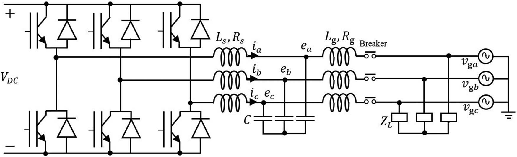
Synchronverter connected to a local load Z L and the power grid.
A synchronverter is formed by the power and control parts [12,13]. The power part has a three-phase full-bridge inverter, a DC source, and an LCL filter. The capacitors in the LCL filter do not consider the internal resistance because of a weakness in the attenuation ability of the LCL filter and because the active power losses increase [38].
The measured phase voltages (e a , e b , e c ) and currents (i a , i b , i c ) in the outer part of the synchronverter are used to compute the delivered active and reactive power (P e , Q e ). The induced voltage calculated in the control part triggers the bridge gates.
Figure 2 shows the block diagram with the control part used to obtain the induced voltage magnitude and the voltage angle θ. Self-synchronized synchronverter comprises three main loops.
![Figure 2
The control part of the synchronverter with the self-synchronized loop [13].](/document/doi/10.1515/nleng-2022-0043/asset/graphic/j_nleng-2022-0043_fig_002.jpg)
The control part of the synchronverter with the self-synchronized loop [13].
The upward loop in Figure 2 covers the frequency regulation control that usually appears in synchronous generators.
Eq. (1) represents the swing equation, where
A proportional integral (PI) controller can keep the difference between the nominal and current frequencies in zero values. The controller avoids sharing power between the inverter and the grid, and it is activated for synchronization purposes through a switch Sw P . Once the synchronverter is synchronized, this switch is turned off.
The electromagnetic torque may be calculated with any of the following expressions:
where M
f
is the mutual inductance between the stator windings and the rotor winding, i
f
is the rotor current, i is the three-phase stator current, P
e
is the delivered power,
An integrator and the moment of inertia (1/Js) produce the grid frequency that is implemented to obtain the angular speed or frequency (
The bottom left loop in Figure 2 represents the excitation of a synchronous machine. The reactive power is set to a specific value (Q set) and the delivered reactive power Q is calculated and fed back into the loop. The voltage magnitude must be calculated using Eq. (6) and filtered out to avoid the second frequency ripples [12].
where v
m
is the voltage magnitude; and v
a
, v
b
, and v
c
are the phase voltages measured in the power grid. The magnitude is subtracted from the nominal voltage and amplified by the voltage-droop coefficient D
q
, that is the ratio of the required change in reactive power
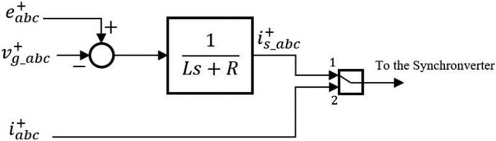
where Q is the calculated reactive power obtained from Eq. (10).
The bottom right loop in Figure 2 is known as the virtual current loop [13]. A virtual current i
s
is calculated using the tracking error between the measured grid voltage v
g and the calculated induced voltage e multiplied by
The operation modes of the self-synchronized synchronverter are summarized in ref. [13].
3 Space vector-based symmetrical decomposition
Three-phase electrical systems are based on three voltages and three currents that interact to provide both active and reactive powers to the loads. In classic theory, a set of balanced signals means the same magnitude and electrical rotational separation of 120°. This assumption is correct in transmission systems, but not all distribution networks comply with such a balance scenario because of the single- and two-phase loads or even the power grid asymmetry.
Power converters particularly need a space vector transformation to deal with these unbalances. This section presents symmetrical component decompositions for both the frequency and time domains.
3.1 Symmetrical components in the frequency domain
Grid-connected power converters are very sensitive to voltage disturbances at the point of common coupling (PCC). When considering sensitivity, it is essential to detect the unbalanced voltage vector properly. The symmetrical decomposition should be performed to accomplish such detection, and it was first presented by Fortescue in 1918 [39]. With this method, a group of three unbalanced voltage or current signals may be separated into three balanced vectors. Those vectors are well known as positive, negative, and zero sequences.
The positive sequence presents a counterclockwise rotation, keeping the abc rotational order. Meanwhile, the negative sequence establishes a clockwise rotation, maintaining the acb rotational order. Both cases have three vectors separated by 120° or 2π/3 radians. There are three vectors with the same magnitude and angle in the zero-sequence signal, which is zero degrees.
To transform from a natural frame to a ( + − 0) frame in the frequency domain, the following transformation must be considered:
After expanding each term, the following voltage vectors and the Fortescue transformation matrix are obtained:
where α = e j2π/3= 1 ∠ 120° is the Fortescue operator, which keeps the vectors 120° apart. Eq. (12) may be used for calculating the sequence components for the phase a in the frequency domain. If necessary, phases b and c can be calculated as well, as observed in Eq. (14).
Whether the voltage or current vectors are expressed in the symmetrical components for the phase a, the transformation to the natural frame can be obtained by:
and [T + − 0]−1 is expressed in Eq. (16):
The above formulation is correct for frequency domain vectors. When signal processing of the voltage and current vectors is needed in the time domain, an adequation should be introduced.
3.2 Symmetrical components in the time domain
The symmetrical components decomposition in the time domain was developed by Lyon [40]. If Eq. (13) proposed by Fortescue is applied to the arrays of unbalanced sinusoidal waveforms presented in Eq. (17), it is possible to obtain the instantaneous variables as in Eqs. (18) and (19).
The Lyon transformation may be expressed in Eq. (20) through a normalized matrix, where
From Eq. (19), it is possible to verify that the resulting vector comprises two complex terms
The α Fortescue operator must be converted from the frequency domain to the time domain in order to obtain the positive- and negative-sequence vectors
![Figure 3
Time-shifting operator (a) implementation in the time domain [42].](/document/doi/10.1515/nleng-2022-0043/asset/graphic/j_nleng-2022-0043_fig_003.jpg)
Time-shifting operator (a) implementation in the time domain [42].
4 Synchronization of the synchronverter
Grid-connected power converters may be synchronized in several ways, such as PLL or FLL [43,44]. In this article, the synchronization process is achieved using the positive-sequence instantaneous values of grid voltage, synchronverter voltage, and the current between the synchronverter and the power grid. These instantaneous values are used to accomplish the synchronization part of the self-synchronized synchronverter presented by Zhong et al. [13].
Each vector is split into a, b, and c phases and introduced in the LPF presented in Figure 3. As a result, every single phase has three resulting signals: the original (v a , v b , v c ), the one shifted by the Lyon operator (av a , av b , av c ), and the one shifted by the square Lyon operator (a 2 v a , a 2 v b , a 2 v c ). Then, the instantaneous positive and negative sequences per phase are calculated using these resulting signals, as in Eqs. (22) and (23).
The same process applies to the power converter output voltage (e abc ) and the current flowing from the converter to the power grid (i abc ).
Figure 4 introduces the synchronization process using the instantaneous positive-sequence values. The terms
Synchronization process using the instantaneous values of the positive-sequence components.
From Figure 4, it is possible to identify the equations used for the synchronization. First, there is a difference between the synchronverter voltage and the grid voltage, and this is useful for calculating a virtual current as follows:
where Ls and R may be the actual or virtual values of the LCL filter connected between the synchronverter and the PCC.
A switch allows the path of the virtual current or the measured current to the synchronverter formulation. While synchronizing, the virtual current is used until the power switch that connects the synchronverter to the grid is closed. At that point, the measured current is the one that is used for calculations for the synchronverter control.
5 Results
The implementation was performed with a three-phase synchronverter connected with a breaker to a balanced and unbalanced power grid and a local resistive load in Simulink-Matlab©. The PWM generation is modeled through a “Universal Bridge” mask together with a “PWM Generator (2-Level)” mask fed by the reference voltage obtained by the synchronverter.
The simulation time was adjusted in two seconds to emulate the synchronization and the entrance of each control loop, namely, frequency droop control, voltage droop control, virtual current, and the connection to the grid with the breaker. The system is presented in Figure 1.
According to ref. [12], there are four switches in synchronverter behavior. Those are SW P which allows the frequency droop control; SW Q that allows voltage droop control; SW Z which changes the current that feeds the synchronverter control from the virtual- to the measured-current; and SW B which is the power breaker that connects the inverter to the power grid.
The simulation model parameters are presented in Table 1, and the switch activation times are shown in Table 2.
Simulation model parameters
| Parameter | Value | Parameter | Value |
|---|---|---|---|
| Line voltage
|
48 | Filter capacitance [µF] | 287.82 |
| Active power [W] | 5,000 | Filter inductance [µH] | 244.46 |
| Reactive power [VAR] | 4,000 | Damping factor [kg m2/s] | 0.7036 |
| Rated frequency [Hz] | 60 | Inertia [µkg m2] | 284.97 |
| Cut-off frequency [rad/s] | 3,770 | Frequency time constant
|
405 |
| Sample time [s] | 1.67 × 10⁻⁶ | Voltage gain (K) | 377 |
| DC capacitance [µF] | 2,000 | Reactive damping [VAR/V] | 721.69 |
| DC voltage [V] | 150 | Voltage time constant (τ v ) [s] | 0.25 |
Switch activation times
| Switch | Time [s] |
|---|---|
| SW P | 0.5 |
| SW Q | 1.0 |
| SW Z | 1.5 |
| SW B | 1.5 |
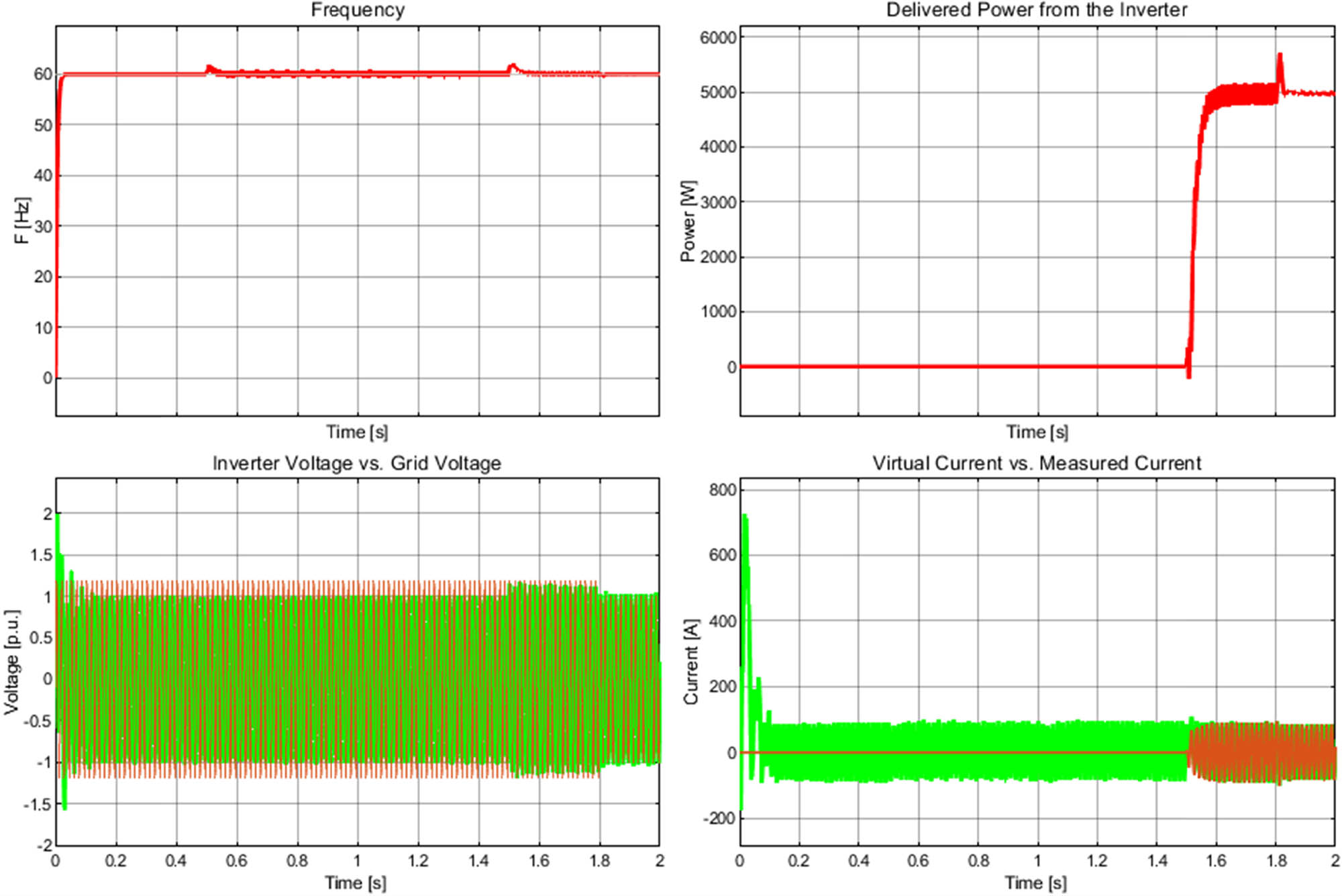
Three scenarios were performed. The first scenario considers the synchronization of both the conventional synchronverter and the proposed positive-sequence synchronization when the voltage grid is balanced. The second scenario considers the synchronization when the voltage grid is unbalanced, and a comparison is performed to demonstrate the effectiveness of the proposed method. Finally, a third scenario is accomplished with a voltage dip of 50% and unbalanced voltage conditions. In the following subsections, these three scenarios are presented and analyzed.
5.1 Synchronization with a balanced power grid
A “Three-Phase Programmable Generator” mask in Simulink© with a phase-voltage amplitude of
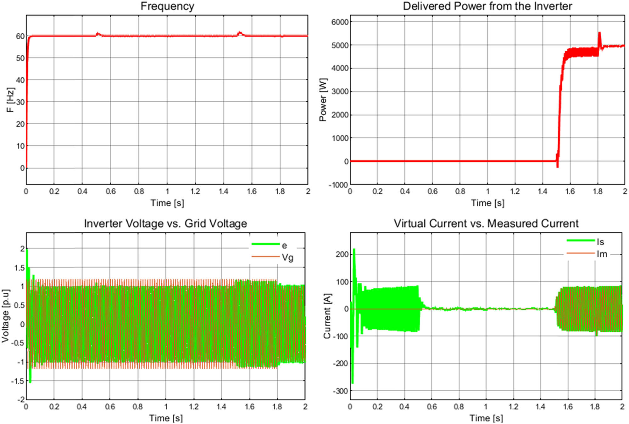
Results from Scenario 1 – connection to a balanced power grid.
From 0 to 0.5 s, the synchronverter is synchronized correctly, and it can be observed from Figure 5 (voltage plot) that the inverter and grid voltages are in phase. After that, the frequency droop control is activated, as observed in the current plot, when the virtual current goes down to zero. At 1.5 s, the measured current goes into the synchronverter control algorithm, and the breaker is closed to allow sharing power with the grid. The active power delivered to the load and the power grid is displayed in the delivered power plot of Figure 5, and it is identified as 5,000 W as set initially. The reactive power is not plotted because it is zero all time, based on the entirely resistive load nature.
Figure 5 also shows that the frequency remains at 60 Hz during the steady state operation, and in transient state behavior, the changes are small enough to be corrected by the frequency droop control loop. Some transients appeared on the inverter voltage e, but were corrected immediately by the voltage droop control loop.
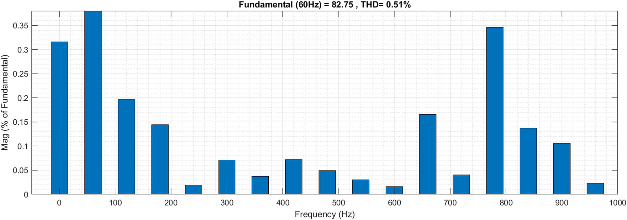
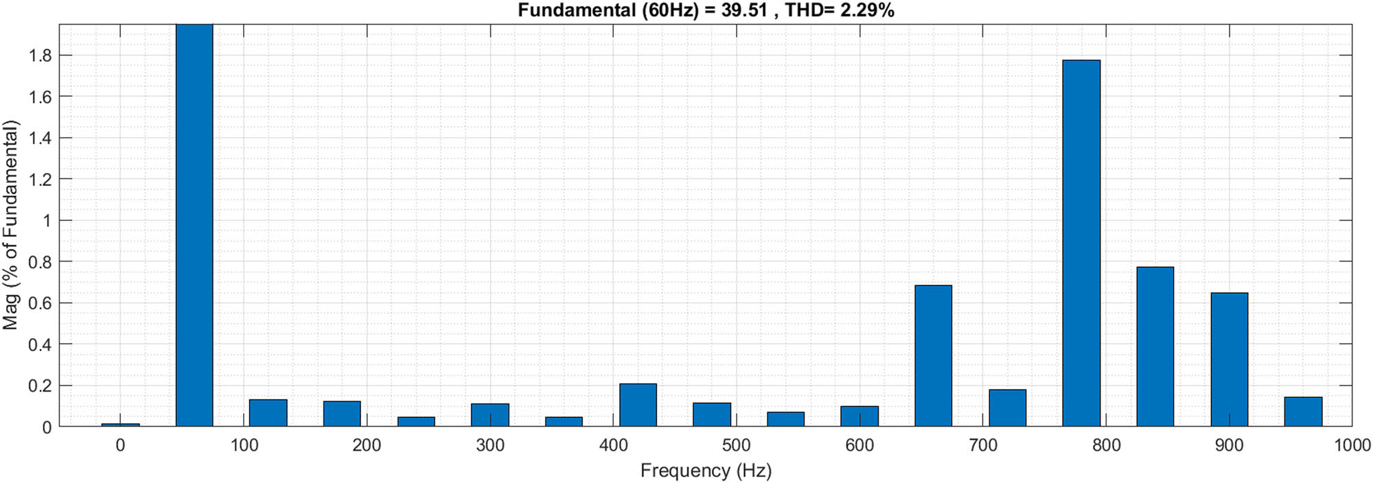
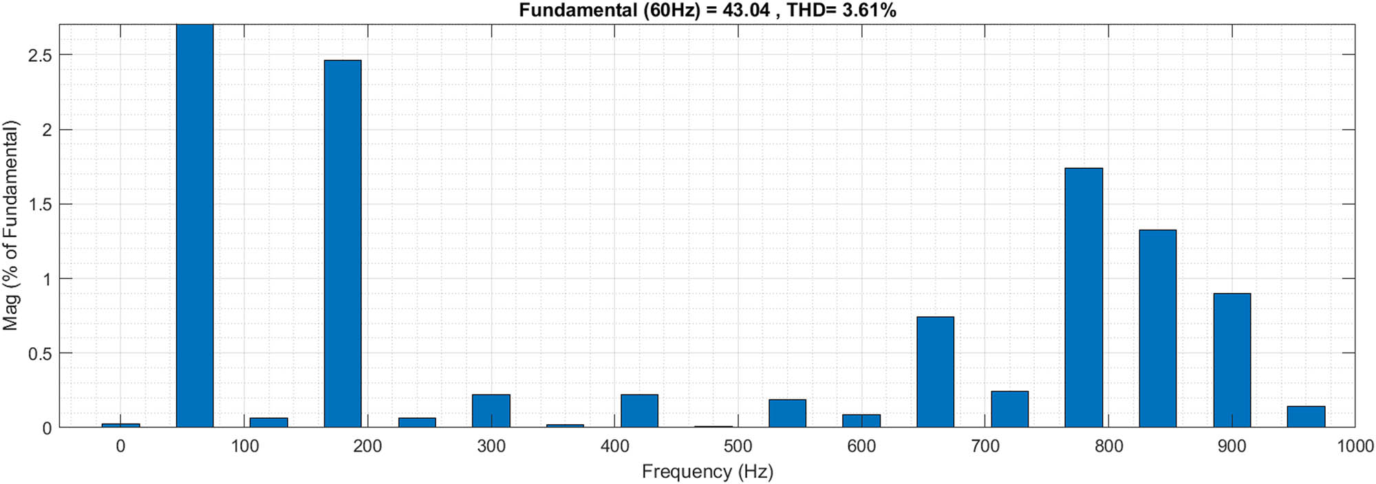
Total harmonic distortion (THD) was computed for the injected current i abc and voltage e abc after the connection has started (at 1.6 s) and through 5 cycles. The harmonic components and THD are illustrated in Figures 6 and 7.
i abc THD. Scenario 1 – connection to a balanced power grid.
e abc THD. Scenario 1 – connection to a balanced power grid.
Figures 6 and 7 show that the THDs for the current and voltage are lower than 3%, which means that the inverter may be connected to the power grid.
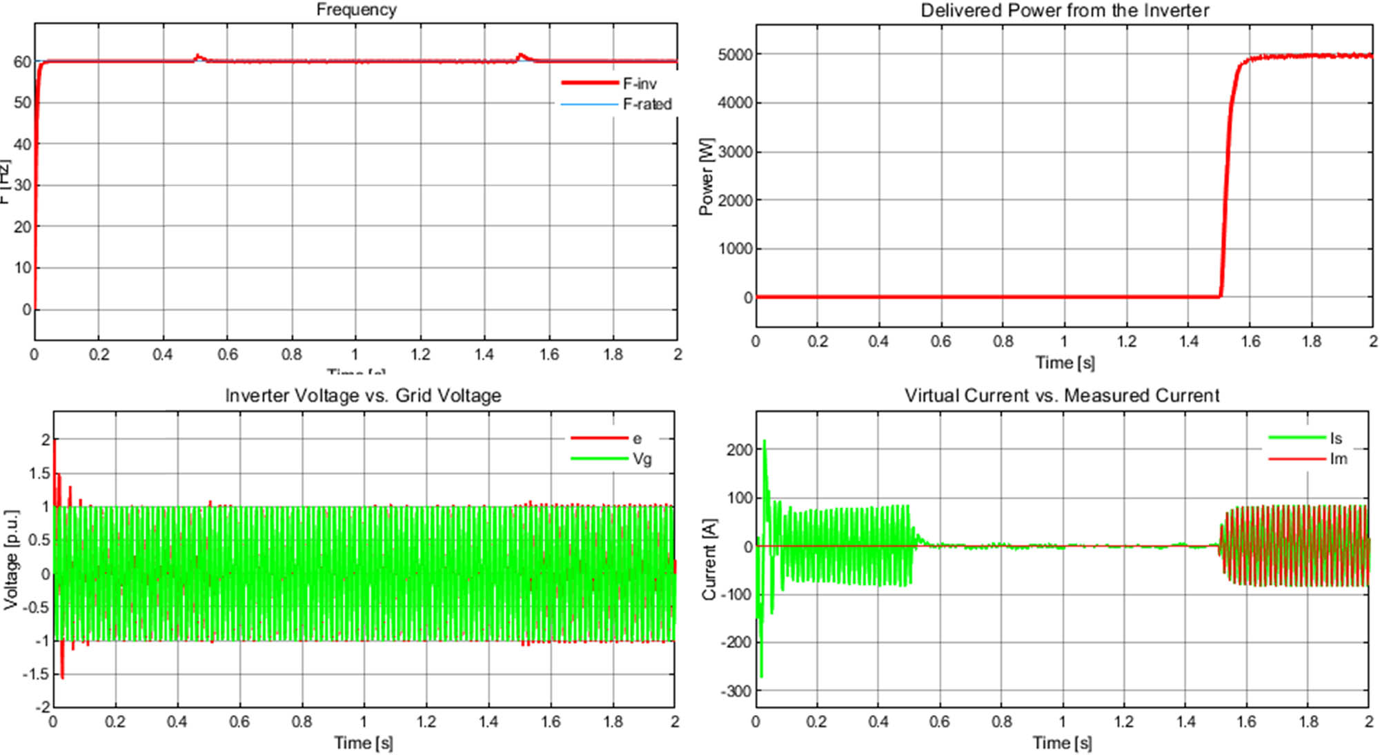
5.2 Synchronization with an unbalanced power grid
The second scenario considers an unbalanced power grid, and it is achieved by a three-phase programmable generator plus three independent controlled voltages in star connection and driven to the ground connector, while the programmable generator feeds the input. The harmonic generation is activated only in the fundamental component (60 Hz) in the negative sequence. The negative-sequence phase voltage amplitude is 8.165 V, approximately 20.83% of the fundamental component, and the phase angle is −30°. Table 3 shows the parameters for generating the unbalanced voltage in the power grid. This scenario is complicated for the inverter because the unbalance percentage is relatively high. Eq. (25) illustrates the unbalance calculation according to the IEEE Standard 1159-2019 [45], where only the positive and negative magnitudes are considered.
Harmonic generation parameters – Three-phase programmable generator
| Magnitude | Value |
|---|---|
| Sequence | Negative |
| Amplitude | 8.165 V |
| Phase | −30° |
| Harmonic order | 1 |
The positive-sequence magnitude for this scenario was 39.192 V, while the negative was 8.165 V. The unbalance percentage is 20.83% and is too high compared with the 3% of the allowed value from the standard mentioned above [45]. Since the inverter can synchronize at this unbalance level, it could work appropriately during normal and real conditions.
Figure 8 presents the results of this scenario. It is important to mention that the voltage plot compares only the phase a of inverter and grid voltages, and the unbalance is not noticeable directly, but the amplitude is different from 1 pu while the harmonic distortion is injected.
Results from Scenario 2 – connection to an unbalanced power grid.
During the first half second, there is a difference between the positive-sequence grid and inverter-sequence voltage, and we can observe it with the existence of the virtual current I s in the current plot. At 0.5 s, the frequency control loop is activated, the virtual current goes to zero, and the voltage waves are synchronized, as shown in the voltage plot in Figure 8. Nonetheless, the phase–voltage amplitudes are not the same until the measured current at 1.5 s is introduced into the synchronverter control algorithm. From the voltage plot, it is possible to observe that the unbalance lasts until 1.8 s when both the grid and the inverter voltages decrease to 1pu because the harmonic injection is not inserted any longer.
The frequency remains at 60 Hz during the steady state operation. There is a slight oscillation during the transient state operation because of the frequency droop control operation and the grid connection through the power breaker. The active power shared to the resistive load starts at 1.5 s when the connection is allowed, and the plot shows an oscillation because of the double frequency component presented in the unbalanced network. Figure 9 provides further information regarding the voltage waveforms.
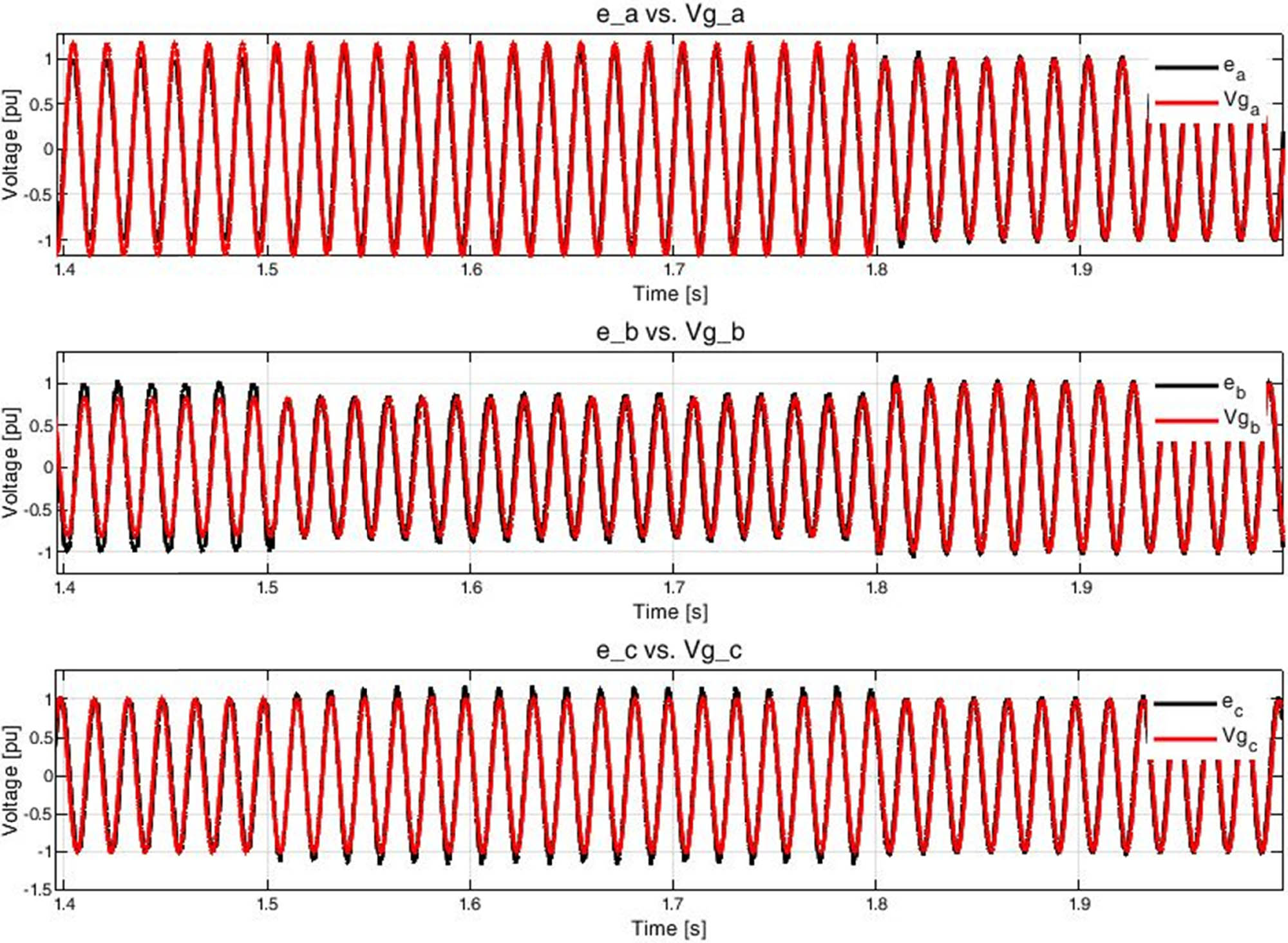
Comparison between per-phase inverter and grid voltages.
The time scale in Figure 9 was reduced from 1.4 to 2 s to better observe the voltage wave shapes. The inverter amplitude is 1 p.u. from the moment the frequency droop control starts up to the moment the power breaker is closed at 1.5 s, as the synchronverter not only follows the frequency of the power grid but the amplitude of the grid voltage too. The negative-sequence injection ends at 1.8 s, which is noticeable because the inverter and grid voltages return to 1 p.u.
The THD was computed for the injected current i abc and voltage e abc after the connection has started (at 1.6 s) and through 5 cycles. The harmonic components and THD are illustrated in Figures 10 and 11. Both figures show, on the positive-sequence synchronization, that the current and voltage THDs are below the limits defined in IEC/EN 61000-2-2 (10% for current and 5% for voltage).
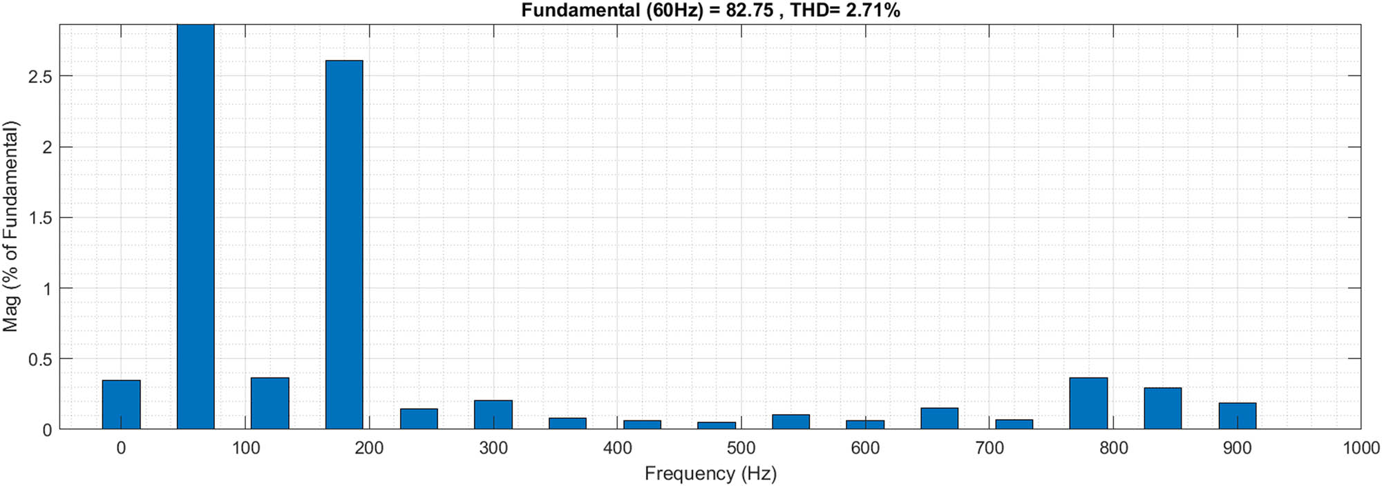
i abc THD. Scenario 2 (proposed method) – connection to an unbalanced power grid.
e abc THD. Scenario 2 (proposed method) – connection to an unbalanced power grid.
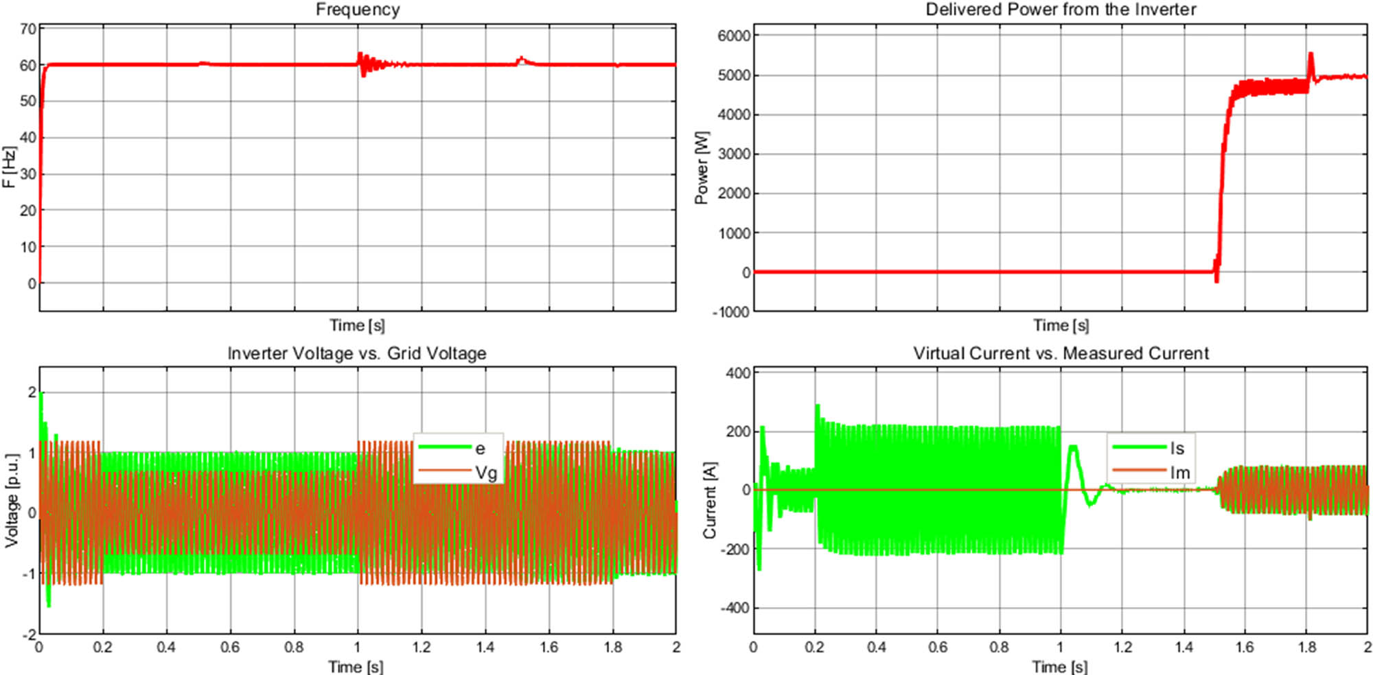
The conventional synchronverter is tested in this scenario to validate the effectiveness of the positive-sequence synchronization method proposed in this article, and its behavior is depicted in Figure 12. The most important point in Figure 12 focuses on the current plot because to get a correct synchronization, the virtual current must be zero after the active power control loop starts its operation at 0.5 s, and obviously, it does not occur. From the above, the conventional synchronverter control strategy is not a good option for connecting an inverter under voltage unbalance conditions. The proposed method is a better option, as depicted in Figures 8 and 9.
Results from scenario 2 – connection of the conventional synchronverter to an unbalanced power grid.
5.3 Synchronization considering a voltage dip of 50%
The third scenario contemplates a voltage dip of 50% together with a voltage unbalance condition. The unbalance voltage is the same as explained in Section 5.2. Again, the simulation time is 2 s. In this case, the voltage dip starts at 0.2 s and ends at 1.0 s to test the synchronization process of the positive-sequence synchronverter.
This scenario is quite complicated for any inverter because it must simultaneously deal with the unbalance condition and voltage dip. This is not usually presented in real conditions because the protection system usually would trigger once the voltage dip is below 90% of the nominal value. The proposed method is evaluated and it can be observed that the voltage waveform follows the grid at the beginning. Once the dip voltage starts, the inverter tries to keep following the grid using its active power control loop by maintaining the nominal voltage. The virtual current increases at 0.2 s because of the dip voltage, but it is essential to highlight that this virtual current is not flowing through any device. The current plot of Figure 13 shows how the virtual current returns to zero once the dip voltage is released and the power sharing is accomplished effectively, as presented in the power plot of Figure 13.
Results from scenario 3 – connection of the positive-sequence synchronverter to an unbalanced grid together with a voltage dip of 50%.
Frequency is almost stable all the time, except for the transient effects of the dip condition and the connection to the power grid (at 1.0 and 1.5 s, respectively). However, the frequency returns rapidly to the fundamental value of 60 Hz.
6 Conclusion
Synchronization is essential for the synchronverter to share the right power with the grid or a local load. Whether the synchronization process is not well accomplished, the stability of the inverter is compromised, the current injection will not be adequate, and the voltage amplitude will not follow the grid.
The positive sequence of the synchronverter voltage and the grid voltage may be used for calculating a virtual current that aids the synchronverter in synchronizing with the power grid. This virtual current helped calculate the excitation voltage, reactive power, and the reference voltage that triggers the MOSFETs or IGBTs through pulses. This current, together with the frequency droop control, is important for accomplishing the synchronization no matter whether the power grid is balanced or unbalanced.
The positive sequence was used in three scenarios to synchronize a synchronverter simulated on Simulink-Matlab©. The first scenario contemplated a balanced power grid and a local 5 kW resistive load. The second scenario considered an unbalanced power grid with an injection of a negative sequence rated at 20.83% of the positive-sequence amplitude and the same load. The third scenario considered the same unbalanced conditions as the second scenario and a voltage dip of 50%. The results showed that the synchronverter followed the grid frequency and the wave shape amplitude after the frequency droop control started in all cases.
In future work, the implemented technique may be used to reduce the unbalance percentage at the PCC when the synchronverter is connected to an unbalanced power grid or a non-symmetrical load.
Acknowledgments
The authors would like to thank Juan Palacios from the Western Autonomous University, Cali, Colombia, for his help in constructing the basis for the simulation model. Also, to Martin Sirový from the University of West Bohemia, in Plzen, Czech Republic, for his guidance in control systems. Finally, to the School of Electromechanical Engineering at the Pedagogical and Technological University of Colombia (Universidad Pedagógica y Tecnológica de Colombia) for the support received in the publication process.
-
Funding information: This research was funded by Universidad Nacional de Colombia, Sede Medellín, through the Hermes Project No. 41933 and the contract FP44842-130-2017 and the Colombian Ministry of Science, Technology, and Innovation – Minciencias (Ministerio de Ciencia, Tecnología e Innovación – Minciencias) through the national call 727-2015.
-
Author contributions: All authors equally contributed to the review of the papers and the writing of the manuscript.
-
Conflict of interest: The authors declare no conflict of interest.
References
[1] Mazari MB, Boudinar AH, Mazari B. Effect of open circuit fault on PMSM drive controlled by sliding mode control and feedback linearization using time and frequency analysis. Int Rev Model Simul. 2018;11(4):235–44.10.15866/iremos.v11i4.14109Suche in Google Scholar
[2] Farhat S, Alaoui R, Kahaji A, Bouhouch L. Wind turbine MPPT strategy with DFIG vector control. Int Rev Model Simul. 2018;11(6):406–13.10.15866/iremos.v11i6.16156Suche in Google Scholar
[3] Yang H, Guerrero JM, Zhao R, Zeng Z. Multi-functional distributed generation unit for power quality enhancement. IET Power Electron. 2015;8(3):467–76.10.1049/iet-pel.2013.0954Suche in Google Scholar
[4] Caicedo J, de Castro AR, Franca B, Aredes M. Resonant harmonic compensation for synchronverter, integrating wind and photovoltaic power generation into an electrical grid, case study: Nonlinear and unbalanced load. 2017 Brazilian Power Electronics Conference (COBEP); 2017 Nov 19-22; Juiz de Fora, Brazil. IEEE; 2018. p. 1–6.10.1109/COBEP.2017.8257275Suche in Google Scholar
[5] Molina E, Candelo-Becerra JE, Hoyos FE. Control strategy to regulate voltage and share reactive power using variable virtual impedance for a microgrid. Appl Sci. 2019;9(22):1–9.10.3390/app9224876Suche in Google Scholar
[6] Garces-Gomez YA, Hoyos FE, Candelo-Becerra JE. Classic discrete control technique and 3D-SVPWM applied to a dual unified power quality conditioner. Appl Sci. 2019;9(23):1–7.10.3390/app9235087Suche in Google Scholar
[7] Pizarro Pérez SA, Candelo-Becerra JE, Hoyos, Velasco FE. Optimal parameters of inverter-based microgrid to improve transient response. Int J Electr Comput Eng. 2020;10(1):637–40.10.11591/ijece.v10i1.pp637-650Suche in Google Scholar
[8] da Silva Junior GP, Barros LS, Barros CMV. Synchronverter coupled to a lithium-ion bank for grid frequency and voltage supports and controlled charge-discharge. Electr Power Syst Res. 2021;197(21):1–8.10.1016/j.epsr.2021.107352Suche in Google Scholar
[9] Yap KY, Lim JMY, Sarimuthu CR. A novel adaptive virtual inertia control strategy under varying irradiance and temperature in grid-connected solar power system. Int J Electr Power Energy Syst. 2021;132(21):1–6.10.1016/j.ijepes.2021.107180Suche in Google Scholar
[10] Vetoshkin L, Müller Z. A comparative analysis of a power system stability with virtual inertia. Energies. 2021;14(11):3277.10.3390/en14113277Suche in Google Scholar
[11] Schulze W, Zajadatz M, Suriyah M, Leibfried T. Emulation of grid-forming inverters using real-time PC and 4-quadrant voltage amplifier. Forsch im Ingenieurwes. 2021;85(2):425–30.10.1007/s10010-021-00484-9Suche in Google Scholar
[12] Zhong Q-C, Weiss G. Synchronverters: Inverters that mimic synchronous generators. IEEE Trans Ind Electron. 2011;58(4):1259–67.10.1109/TIE.2010.2048839Suche in Google Scholar
[13] Zhong QC, Nguyen PL, Ma Z, Sheng W. Self-synchronized synchronverters: Inverters without a dedicated synchronization unit. IEEE Trans Power Electron. 2014;29(2):617–30.10.1109/TPEL.2013.2258684Suche in Google Scholar
[14] Nguyen PL, Zhong QC, Blaabjerg F, Guerrero JM. Synchronverter-based operation of STATCOM to mimic synchronous condensers. 2012 7th IEEE Conference on Industrial Electronics and Applications (ICIEA); 2012 Jul 18-20; Singapore. IEEE; 2012. p. 942–7.10.1109/ICIEA.2012.6360859Suche in Google Scholar
[15] Arani MF, El-Saadany EF. Implementing virtual inertia in DFIG-based wind power generation. IEEE Trans Power Syst. 2013;28(2):1373–4.10.1109/TPWRS.2012.2207972Suche in Google Scholar
[16] Zhong QC, Ma Z, Nguyen PL. PWM-controlled rectifiers without the need of an extra synchronisation unit. IECON 2012 – 38th Annual Conference on IEEE Industrial Electronics Society; 2012 Oct 25-28; Montreal, Canada. IEEE; 2012. p. 691–5.10.1109/IECON.2012.6388668Suche in Google Scholar
[17] Ma Z, Zhong Q-C, Yan JD. Synchronverter-based control strategies for three-phase PWM rectifiers. 2012 7th IEEE Conference on Industrial Electronics and Applications (ICIEA); 2012 Jul 18-20; Singapore. IEEE; 2012. p. 225–30.10.1109/ICIEA.2012.6360727Suche in Google Scholar
[18] Ming W, Zhong Q. Synchronverter-based transformerless PV inverters. IECON 2014 – 40th Annual Conference of the IEEE Industrial Electronics Society; 2014 Oct 29 - Nov 1; Dallas (TX), USA. IEEE; 2015. p. 4396–401.10.1109/IECON.2014.7049164Suche in Google Scholar
[19] D’Arco S, Suul JA, Fosso OB. Small-signal modeling and parametric sensitivity of a virtual synchronous machine in islanded operation. Int J Electr Power Energy Syst. 2015;72(1):3–5.10.1016/j.ijepes.2015.02.005Suche in Google Scholar
[20] Aouini R, Marinescu B, Ben Kilani K, Elleuch M. Improvement of transient stability in an AC/DC system with synchronverter based HVDC. 2015 IEEE 12th International Multi-Conference on Systems, Signals & Devices (SSD15); 2015 Mar 16-19; Mahdia, Tunisia. IEEE; 2015. p. 1–6.10.1109/SSD.2015.7348137Suche in Google Scholar
[21] Brown E, Weiss G. Using synchronverters for power grid stabilization. 2014 IEEE 28th Convention of Electrical & Electronics Engineers in Israel (IEEEI); 2014 Dec 3-5; Eilat, Israel. IEEE; 2015. p. 1–5.10.1109/EEEI.2014.7005736Suche in Google Scholar
[22] Aouini R, Ben Kilani K, Marinescu B, Elleuch M. Virtual synchronous generators dynamic performances. 2014 International Conference on Electrical Sciences and Technologies in Maghreb (CISTEM); 2014 Nov 3-6; Tunis, Tunisia. IEEE; 2015. p. 1–6.10.1109/CISTEM.2014.7077025Suche in Google Scholar
[23] Zhang CH, Zhong QC, Meng JS, Chen X, Huang Q, Chen SH, et al. An Improved Synchronverter Model and its Dynamic Behaviour Comparison with Synchronous Generator. 2nd IET Renewable Power Generation Conference (RPG 2013); 2013 Sep 9-11; Beijing, China. IEEE; 2014. p. 1–4.10.1049/cp.2013.1879Suche in Google Scholar
[24] Shuai Z, Hu Y, Peng Y, Tu C, Shen ZJ. Dynamic stability analysis of synchronverter-dominated microgrid based on bifurcation theory. IEEE Trans Ind Electron. 2017;64(9):7467.10.1109/TIE.2017.2652387Suche in Google Scholar
[25] Luo S, Wu W, Koutroulis E, Chung HSH, Blaabjerg F. A new virtual oscillator control without third-harmonics injection for DC/AC inverter. IEEE Trans Power Electron. 2021;36(9):10879–88.10.1109/TPEL.2021.3066162Suche in Google Scholar
[26] Sevilmiş F, Karaca H. An advanced hybrid pre-filtering/in-loop-filtering based PLL under adverse grid conditions. Eng Sci Technol an Int J. 2021;24(5):1144–52.10.1016/j.jestch.2021.02.011Suche in Google Scholar
[27] Ahmad S, Mekhilef S, Mokhlis H. An improved power control strategy for grid-connected hybrid microgrid without park transformation and phase-locked loop system. Int Trans Electr Energy Syst. 2021;31(7):1–2.10.1002/2050-7038.12922Suche in Google Scholar
[28] Rajan R, Fernandez FM, Yang Y. Primary frequency control techniques for large-scale PV-integrated power systems: A review. Renew Sustain Energy Rev. 2021;144(1):1–8.10.1016/j.rser.2021.110998Suche in Google Scholar
[29] Phoeurn S, Somkun S. A study of a single phase grid connected pv inverter performance under a weak grid condition and distorted grid voltage for Cambodia. Int J Power Electron Drive Syst. 2021;12(2):1055–8.10.11591/ijpeds.v12.i2.pp1055-1068Suche in Google Scholar
[30] Li M, Zhang X, Guo Z, Wang J, Wang Y, Li F, et al. The control strategy for the grid-connected inverter through impedance reshaping in q-axis and its stability analysis under a weak grid. IEEE J Emerg Sel Top Power Electron. 2021;9(3):3229–32.10.1109/JESTPE.2020.3024863Suche in Google Scholar
[31] Madhav GV, Nagamani C, Rao BN. Adaptive control techniques integrated to grid-connected RES with harmonic filter capabilities. Int J Eng Trends Technol. 2021;69(2):201–6.10.14445/22315381/IJETT-V69I2P228Suche in Google Scholar
[32] Rong S, Ma J, Chen X, Guan W, Hao W, Cui J, et al. Steady-state stability analysis of synchronization loops in weak-grid-connected microgrid. IOP Conf Ser: Earth Environ Sci. 2021;742(1):012006.10.1088/1755-1315/742/1/012006Suche in Google Scholar
[33] Nirmal S, Sivarajan KN, Jasmin EA. Phase shift control and controller area network assisted proportional resonant control for grid integration of single phase voltage source inverters. IET Power Electron. 2021;14(7):1371–3.10.1049/pel2.12134Suche in Google Scholar
[34] Gupta Y, Parganiha N, Rathore AK, Doolla S. An improved reactive power sharing method for an islanded microgrid. IEEE Trans Ind Appl. 2021;57(3):2954–63.10.1109/IAS.2019.8911936Suche in Google Scholar
[35] Zheng T, Chen L, Guo Y, Mei S. Comprehensive control strategy of virtual synchronous generator under unbalanced voltage conditions. IET Gener Transm Distrib. 2018;12(7):1621–30.10.1049/iet-gtd.2017.0523Suche in Google Scholar
[36] Li F, Liu G, Zhu K, Wang W. An Improved Control Strategy of Virtual Synchronous Generator under Unbalanced Conditions. 2018 IEEE 4th Southern Power Electronics Conference (SPEC); 2018 Dec 10-13; Singapore. IEEE; 2019. p. 1–6.10.1109/SPEC.2018.8636005Suche in Google Scholar
[37] Elkhatib ME, Du W, Lasseter RH. Evaluation of inverter-based grid frequency support using frequency-watt and grid-forming PV inverters. 2018 IEEE Power Energy Society General Meeting; 2018 Aug 5-10; Portland (OG), USA. IEEE; 2018. p. 1–5.10.1109/PESGM.2018.8585958Suche in Google Scholar
[38] Abed ZM, Hassan TK, Hameed KR. Analysis and design of photovoltaic three-phase grid-connected inverter using passivity-based control. Int J Power Electron Drive Syst. 2022;13(1):167.10.11591/ijpeds.v13.i1.pp167-177Suche in Google Scholar
[39] Fortescue CL. Method of symmetrical co-ordinates applied to the solution of polyphase networks. Trans Am Inst Electr Eng. 1918;37(2):1027–140.10.1109/T-AIEE.1918.4765570Suche in Google Scholar
[40] Lyon WV. Application of the Method of Symmetrical Components. 1st ed. New York: McGraw-Hill; 1937.Suche in Google Scholar
[41] Iravani MR, Karimi-Ghartemani M. Online estimation of steady state and instantaneous symmetrical components. IEE Proc – Gener Transm Distrib. 2003;150(5):616–22.10.1049/ip-gtd:20030779Suche in Google Scholar
[42] Teodorescu R, Liserre M, Rodríguez P. Grid Converters for Photovoltaic and Wind Power Systems. 1st ed. West Sussex: John Wiley & Sons, Ltd; 2011.10.1002/9780470667057Suche in Google Scholar
[43] Kewat S, Singh B. Grid Synchronization of WEC-PV-BES Based Distributed Generation System using Robust Control Strategy. 2019 IEEE Industry Applications Society Annual Meeting; 2019 Sep 29-Oct 3; Baltimore (MD), USA. IEEE; 2019. p. 1–8.10.1109/IAS.2019.8912332Suche in Google Scholar
[44] Chen J, Liu M, O’Donnell T, Milano F. Impact of Current Transients on the Synchronization Stability Assessment of Grid-Feeding Converters. IEEE Trans Power Syst. 2020;35(5):4131–4.10.1109/TPWRS.2020.3009858Suche in Google Scholar
[45] IEEE Std 1159-2019. IEEE Recommended Practice for Monitoring Electric Power Quality. 2019, IEEE Standard 1159-2019 (Revision of IEEE Std 1159-2009); 2019.Suche in Google Scholar
© 2022 Michell J. Quintero-Duran et al., published by De Gruyter
This work is licensed under the Creative Commons Attribution 4.0 International License.
Artikel in diesem Heft
- Research Articles
- Fractal approach to the fluidity of a cement mortar
- Novel results on conformable Bessel functions
- The role of relaxation and retardation phenomenon of Oldroyd-B fluid flow through Stehfest’s and Tzou’s algorithms
- Damage identification of wind turbine blades based on dynamic characteristics
- Improving nonlinear behavior and tensile and compressive strengths of sustainable lightweight concrete using waste glass powder, nanosilica, and recycled polypropylene fiber
- Two-point nonlocal nonlinear fractional boundary value problem with Caputo derivative: Analysis and numerical solution
- Construction of optical solitons of Radhakrishnan–Kundu–Lakshmanan equation in birefringent fibers
- Dynamics and simulations of discretized Caputo-conformable fractional-order Lotka–Volterra models
- Research on facial expression recognition based on an improved fusion algorithm
- N-dimensional quintic B-spline functions for solving n-dimensional partial differential equations
- Solution of two-dimensional fractional diffusion equation by a novel hybrid D(TQ) method
- Investigation of three-dimensional hybrid nanofluid flow affected by nonuniform MHD over exponential stretching/shrinking plate
- Solution for a rotational pendulum system by the Rach–Adomian–Meyers decomposition method
- Study on the technical parameters model of the functional components of cone crushers
- Using Krasnoselskii's theorem to investigate the Cauchy and neutral fractional q-integro-differential equation via numerical technique
- Smear character recognition method of side-end power meter based on PCA image enhancement
- Significance of adding titanium dioxide nanoparticles to an existing distilled water conveying aluminum oxide and zinc oxide nanoparticles: Scrutinization of chemical reactive ternary-hybrid nanofluid due to bioconvection on a convectively heated surface
- An analytical approach for Shehu transform on fractional coupled 1D, 2D and 3D Burgers’ equations
- Exploration of the dynamics of hyperbolic tangent fluid through a tapered asymmetric porous channel
- Bond behavior of recycled coarse aggregate concrete with rebar after freeze–thaw cycles: Finite element nonlinear analysis
- Edge detection using nonlinear structure tensor
- Synchronizing a synchronverter to an unbalanced power grid using sequence component decomposition
- Distinguishability criteria of conformable hybrid linear systems
- A new computational investigation to the new exact solutions of (3 + 1)-dimensional WKdV equations via two novel procedures arising in shallow water magnetohydrodynamics
- A passive verses active exposure of mathematical smoking model: A role for optimal and dynamical control
- A new analytical method to simulate the mutual impact of space-time memory indices embedded in (1 + 2)-physical models
- Exploration of peristaltic pumping of Casson fluid flow through a porous peripheral layer in a channel
- Investigation of optimized ELM using Invasive Weed-optimization and Cuckoo-Search optimization
- Analytical analysis for non-homogeneous two-layer functionally graded material
- Investigation of critical load of structures using modified energy method in nonlinear-geometry solid mechanics problems
- Thermal and multi-boiling analysis of a rectangular porous fin: A spectral approach
- The path planning of collision avoidance for an unmanned ship navigating in waterways based on an artificial neural network
- Shear bond and compressive strength of clay stabilised with lime/cement jet grouting and deep mixing: A case of Norvik, Nynäshamn
- Communication
- Results for the heat transfer of a fin with exponential-law temperature-dependent thermal conductivity and power-law temperature-dependent heat transfer coefficients
- Special Issue: Recent trends and emergence of technology in nonlinear engineering and its applications - Part I
- Research on fault detection and identification methods of nonlinear dynamic process based on ICA
- Multi-objective optimization design of steel structure building energy consumption simulation based on genetic algorithm
- Study on modal parameter identification of engineering structures based on nonlinear characteristics
- On-line monitoring of steel ball stamping by mechatronics cold heading equipment based on PVDF polymer sensing material
- Vibration signal acquisition and computer simulation detection of mechanical equipment failure
- Development of a CPU-GPU heterogeneous platform based on a nonlinear parallel algorithm
- A GA-BP neural network for nonlinear time-series forecasting and its application in cigarette sales forecast
- Analysis of radiation effects of semiconductor devices based on numerical simulation Fermi–Dirac
- Design of motion-assisted training control system based on nonlinear mechanics
- Nonlinear discrete system model of tobacco supply chain information
- Performance degradation detection method of aeroengine fuel metering device
- Research on contour feature extraction method of multiple sports images based on nonlinear mechanics
- Design and implementation of Internet-of-Things software monitoring and early warning system based on nonlinear technology
- Application of nonlinear adaptive technology in GPS positioning trajectory of ship navigation
- Real-time control of laboratory information system based on nonlinear programming
- Software engineering defect detection and classification system based on artificial intelligence
- Vibration signal collection and analysis of mechanical equipment failure based on computer simulation detection
- Fractal analysis of retinal vasculature in relation with retinal diseases – an machine learning approach
- Application of programmable logic control in the nonlinear machine automation control using numerical control technology
- Application of nonlinear recursion equation in network security risk detection
- Study on mechanical maintenance method of ballasted track of high-speed railway based on nonlinear discrete element theory
- Optimal control and nonlinear numerical simulation analysis of tunnel rock deformation parameters
- Nonlinear reliability of urban rail transit network connectivity based on computer aided design and topology
- Optimization of target acquisition and sorting for object-finding multi-manipulator based on open MV vision
- Nonlinear numerical simulation of dynamic response of pile site and pile foundation under earthquake
- Research on stability of hydraulic system based on nonlinear PID control
- Design and simulation of vehicle vibration test based on virtual reality technology
- Nonlinear parameter optimization method for high-resolution monitoring of marine environment
- Mobile app for COVID-19 patient education – Development process using the analysis, design, development, implementation, and evaluation models
- Internet of Things-based smart vehicles design of bio-inspired algorithms using artificial intelligence charging system
- Construction vibration risk assessment of engineering projects based on nonlinear feature algorithm
- Application of third-order nonlinear optical materials in complex crystalline chemical reactions of borates
- Evaluation of LoRa nodes for long-range communication
- Secret information security system in computer network based on Bayesian classification and nonlinear algorithm
- Experimental and simulation research on the difference in motion technology levels based on nonlinear characteristics
- Research on computer 3D image encryption processing based on the nonlinear algorithm
- Outage probability for a multiuser NOMA-based network using energy harvesting relays