Outage probability for a multiuser NOMA-based network using energy harvesting relays
-
Rifqah Press


Abstract
This article evaluates the energy-harvesting capabilities of a multiuser non-orthogonal multiple access-based system, where energy harvesting relays utilise the power splitting relaying protocol to harvest energy and amplify-and-forward protocol to forward the signals to the connected users. The expressions for each user’s energy harvesting outage probability are calculated and compared to the same system model without energy harvesting. Simulation results show the effectiveness of the energy-harvesting relay nodes and the improved outage probability of each user.
1 Introduction
Energy harvesting in wireless communication networks has garnered much attention recently; it is a proposed solution to self-sustaining and lifetime extension of wireless networks. It is argued that battery replacement and charging can be done; however, it can be costly and inconvenient, especially if the location of the batteries is not ideal. There are environmental energy-harvesting techniques such as wind, solar, and vibration; however, radio frequency (RF) wireless energy transfer is a more controlled, convenient, and safer way to harvest energy from the environment. RF signals contain information and energy; thus, an energy-harvesting node can simultaneously harvest and process information. A relay in a cooperative wireless network needs to have sufficient energy to stay active; therefore, a relay node with energy-harvesting capabilities is an excellent advantage in a wireless network [1,2].
Research in cooperative networks shows the benefits of energy-harvesting nodes, such as an increase in the life span of the nodes and the self-sustainability of a communication network, especially for 5G applications. The energy-harvesting employs different receiver architectures, power splitting, and time switching, thus enabling two protocols: power splitting relaying (PSR) and time switching relaying (TSR). The authors of refs [3,4,5,6] utilise the most widely used PSR protocol, whereas ref. [7] utilises the TSR protocol. However, refs [8] and [2] utilise both protocols and evaluate the performance of each. Moreover, ref. [8] reports the superiority of the PSR protocol, whereas ref. [2] reports that the latter is superior. Many researchers only implement one energy-harvesting scheme into their system model; however, refs [3] and [9] implement three different relay schemes. To explore the comparison of the proposed schemes, [3] implements adaptable PSR schemes, whereas [9] increases the security of the communication system. The previous studies [9,10] focus on the physical layer security of the communication system, where the base station transmits a jamming signal to mitigate interference from the eavesdropper node.
2 System model
The system model is similar to that shown in ref. [11]; however, the two relays employ energy-harvesting capabilities. This article follows the layout and the method presented in ref. [11]: the system model in which user connections, time subslots, power allocation, decoding order, and outage probability conditions are the same, thus avoiding repetition.
2.1 Time sub-slot
t
s
1
The active users in the network are

System model 1.
The received signals at
The decoding order follows that of ref. [11], for time sub-slot
The decoded SINRs at
The energy-harvesting does not affect
With the remaining power of the received signal
The decoded SINR at relays
In the first block-time, the energy-harvesting receiver at
The harvested energy is used to power the relays; thus, the relay power is given by
2.2 Time sub-slot
t
s
2
In the second block-time, the amplify-and-forward (AF) protocol utilises an amplifying factor
The relays regenerate the signals for the users connected to it with the amplification given by Eqs. (21) and (22).
The received signals of
Combining Eqs. (19)–(24), the decoded SINRs at
2.3 Time sub-slot
t
s
3
In this time sub-slot, the UEs status changes according to their new locations as shown in Figure 2, with the following connections:

System model 2.
The received signals at
The decoded SINRs at
As previously stated in Section 2.1, the PSR protocol splits the received signal by
Eqs. (37)–(40) give the decoded SINR at the relays in time sub-slot
The energy-harvesting equations in Section 2.1 are not time dependent; thus, they are utilised in this time sub-slot as well.
2.4 Time sub-slot
t
s
4
The relays regenerate the signals for the users connected to it, given by the following equations:
The received signals of
The decoded SINRs at
3 Energy-harvesting outage probability
The outage probability for energy harvesting is similar to that presented in ref. [11]. For generality, the conditions for communication interruption or an outage event may occur if one of the following conditions hold:
If a user cannot detect the signals of higher-powered users.
If a relay cannot detect the signals of higher-powered users.
If a relay cannot detect the signals of the users connected to it.
If the user throughput is not able to achieve the target rate
See reference [11] for more details.
3.1 Outage probability for
UE
1
Outage probability for
Outage probability for
3.2 Outage probability for
UE
2
Outage probability for
Outage probability for
3.3 Outage probability for
UE
3
Outage probability for
Outage probability for
3.4 Outage probability for
UE
4
Outage probability for
Outage probability for
4 Simulation results
The simulation model is shown in Figures 1 and 2, with the energy-harvesting relay nodes. The system model has one BS, two relays
System parameters
|
|
Base station power |
|---|---|
|
|
Figure 1 channel variances |
|
|
Figure 2 channel variances |
|
|
Target rate |
|
|
Power splitting coefficient |
|
|
Energy conversion efficiency |
|
|
Transmit power |
The simulation results show the outage probability of UEs in the various time sub-slots. Figure 3 shows the outage probability of

Outage probability of user 1.
Figure 4 shows the outage probability of
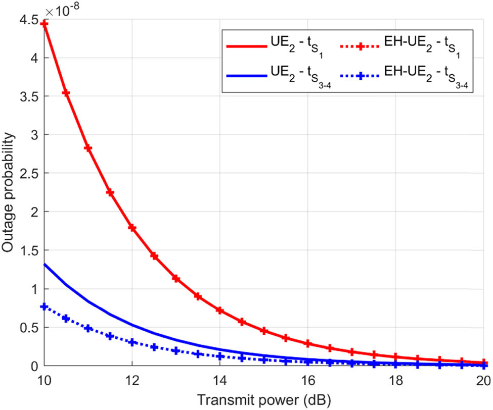
Outage probability of user 2.
Figures 5 and 6 show the outage probability of

Outage probability of user 3.

Outage probability of user 4.
5 Conclusion
This article evaluated the effectiveness of the energy-harvesting relay nodes on the user’s outage probability. The four-user NOMA-based network utilises energy-harvesting relays to communicate with the base station. This research is an adaptation and extension of the research presented by ref. [11], utilising the same methods and procedures to derive the outage probability expressions. The results simply show the impact of the energy harvesting on the outage probability of the users as well as their positions in the network. The cell edge users connected to the relays benefit from the harvested energy by receiving more power than the network without harvesting, which can be seen in the results. Future works may include the physical layer security of the energy-harvesting network by implementing a jamming signal to mitigate eavesdropping.
-
Funding information: The authors state no funding involved.
-
Author contributions: All authors have accepted responsibility for the entire content of this manuscript and approved its submission.
-
Conflict of interest: The authors state no conflict of interest.
References
[1] Shi L, Zhao L, Liang K. Power allocation for wireless powered MIMO transmissions with non-linear RF energy conversion models. China Commun. 2017;4(2):57–64.10.1109/CC.2017.7868175Search in Google Scholar
[2] Nasir AA, Zhou X, Durrani S, Kennedy RA. Relaying protocols for wireless energy harvesting and information processing. IEEE Trans Wirel Commun. 2013;12(17):3622–36.10.1109/TWC.2013.062413.122042Search in Google Scholar
[3] Mondal S, Dharroy S, Kundu S. Adaptive energy harvesting with relay selection schemes in an ordered NOMA network; In 2020 National Conference on Communications; 2020 Feb 21–24; Kharagpur, India. IEEE, 2020. p. 1–6.10.1109/NCC48643.2020.9056072Search in Google Scholar
[4] Guo C, Xin J, Zhao L, Chu X. Performance analysis of cooperative NOMA with energy harvesting in multi-cell networks. China Commun. 2019;16(11):120–9.10.23919/JCC.2019.11.010Search in Google Scholar
[5] Alsharoa A, Ghazzai H, Kamal AE, Kadri A. Near optimal power splitting protocol for energy harvesting based two way multiple relay systems; 2017 IEEE Wireless Communications and Networking Conference (WCNC); 2017 Mar 19–22; San Francisco (CA), USA. IEEE, 2017. p. 1–6.10.1109/WCNC.2017.7925700Search in Google Scholar
[6] Wang T, Lu G, Ye Y, Ren Y. Dynamic power splitting strategy for SWIPT based two-way multiplicative AF relay networks with nonlinear energy harvesting model. Wirel Commun Mob Comput. 2018;2018:1–9.10.1155/2018/1802063Search in Google Scholar
[7] Li F, Jiang H, Fan R, Tan P. Cognitive Non-Orthogonal Multiple Access With Energy Harvesting: An Optimal Resource Allocation Approach. IEEE Trans Veh Technol. 2019;68(7):7080–95.10.1109/TVT.2019.2919261Search in Google Scholar
[8] Du G, Xiong K, Qiu Z. Outage analysis of cooperative transmission with energy harvesting relay: Time switching versus power splitting. Math Probl Eng. 2015;2015:598290.10.1155/2015/598290Search in Google Scholar
[9] Salem A, Musavian L, Jorswieck E, Aissa S. Secrecy outage probability of energy-harvesting cooperative NOMA transmissions with relay selection. IEEE Trans Green Commun Netw. 2020;4(4):1130–48.10.1109/TGCN.2020.2999815Search in Google Scholar
[10] Le TA, Kong HY. Evaluating the performance of cooperative NOMA with energy harvesting under physical layer security. Wirel Pers Commun. 2019 Sep 4;108(2):1037–54.10.1007/s11277-019-06452-5Search in Google Scholar
[11] Balyan V, Daniels R. Resource allocation for NOMA based networks using relays: cell centre and cell edge users. Int J Smart Sens Intell Syst. 2020;13(1):1–18.10.21307/ijssis-2020-031Search in Google Scholar
[12] Balyan V. Cooperative relay to relay communication using NOMA for energy efficient wireless communication. Springer Telecommun Syst. 2021;76(2):14.10.1007/s11235-021-00756-3Search in Google Scholar
© 2022 the author(s), published by De Gruyter
This work is licensed under the Creative Commons Attribution 4.0 International License.
Articles in the same Issue
- Research Articles
- Fractal approach to the fluidity of a cement mortar
- Novel results on conformable Bessel functions
- The role of relaxation and retardation phenomenon of Oldroyd-B fluid flow through Stehfest’s and Tzou’s algorithms
- Damage identification of wind turbine blades based on dynamic characteristics
- Improving nonlinear behavior and tensile and compressive strengths of sustainable lightweight concrete using waste glass powder, nanosilica, and recycled polypropylene fiber
- Two-point nonlocal nonlinear fractional boundary value problem with Caputo derivative: Analysis and numerical solution
- Construction of optical solitons of Radhakrishnan–Kundu–Lakshmanan equation in birefringent fibers
- Dynamics and simulations of discretized Caputo-conformable fractional-order Lotka–Volterra models
- Research on facial expression recognition based on an improved fusion algorithm
- N-dimensional quintic B-spline functions for solving n-dimensional partial differential equations
- Solution of two-dimensional fractional diffusion equation by a novel hybrid D(TQ) method
- Investigation of three-dimensional hybrid nanofluid flow affected by nonuniform MHD over exponential stretching/shrinking plate
- Solution for a rotational pendulum system by the Rach–Adomian–Meyers decomposition method
- Study on the technical parameters model of the functional components of cone crushers
- Using Krasnoselskii's theorem to investigate the Cauchy and neutral fractional q-integro-differential equation via numerical technique
- Smear character recognition method of side-end power meter based on PCA image enhancement
- Significance of adding titanium dioxide nanoparticles to an existing distilled water conveying aluminum oxide and zinc oxide nanoparticles: Scrutinization of chemical reactive ternary-hybrid nanofluid due to bioconvection on a convectively heated surface
- An analytical approach for Shehu transform on fractional coupled 1D, 2D and 3D Burgers’ equations
- Exploration of the dynamics of hyperbolic tangent fluid through a tapered asymmetric porous channel
- Bond behavior of recycled coarse aggregate concrete with rebar after freeze–thaw cycles: Finite element nonlinear analysis
- Edge detection using nonlinear structure tensor
- Synchronizing a synchronverter to an unbalanced power grid using sequence component decomposition
- Distinguishability criteria of conformable hybrid linear systems
- A new computational investigation to the new exact solutions of (3 + 1)-dimensional WKdV equations via two novel procedures arising in shallow water magnetohydrodynamics
- A passive verses active exposure of mathematical smoking model: A role for optimal and dynamical control
- A new analytical method to simulate the mutual impact of space-time memory indices embedded in (1 + 2)-physical models
- Exploration of peristaltic pumping of Casson fluid flow through a porous peripheral layer in a channel
- Investigation of optimized ELM using Invasive Weed-optimization and Cuckoo-Search optimization
- Analytical analysis for non-homogeneous two-layer functionally graded material
- Investigation of critical load of structures using modified energy method in nonlinear-geometry solid mechanics problems
- Thermal and multi-boiling analysis of a rectangular porous fin: A spectral approach
- The path planning of collision avoidance for an unmanned ship navigating in waterways based on an artificial neural network
- Shear bond and compressive strength of clay stabilised with lime/cement jet grouting and deep mixing: A case of Norvik, Nynäshamn
- Communication
- Results for the heat transfer of a fin with exponential-law temperature-dependent thermal conductivity and power-law temperature-dependent heat transfer coefficients
- Special Issue: Recent trends and emergence of technology in nonlinear engineering and its applications - Part I
- Research on fault detection and identification methods of nonlinear dynamic process based on ICA
- Multi-objective optimization design of steel structure building energy consumption simulation based on genetic algorithm
- Study on modal parameter identification of engineering structures based on nonlinear characteristics
- On-line monitoring of steel ball stamping by mechatronics cold heading equipment based on PVDF polymer sensing material
- Vibration signal acquisition and computer simulation detection of mechanical equipment failure
- Development of a CPU-GPU heterogeneous platform based on a nonlinear parallel algorithm
- A GA-BP neural network for nonlinear time-series forecasting and its application in cigarette sales forecast
- Analysis of radiation effects of semiconductor devices based on numerical simulation Fermi–Dirac
- Design of motion-assisted training control system based on nonlinear mechanics
- Nonlinear discrete system model of tobacco supply chain information
- Performance degradation detection method of aeroengine fuel metering device
- Research on contour feature extraction method of multiple sports images based on nonlinear mechanics
- Design and implementation of Internet-of-Things software monitoring and early warning system based on nonlinear technology
- Application of nonlinear adaptive technology in GPS positioning trajectory of ship navigation
- Real-time control of laboratory information system based on nonlinear programming
- Software engineering defect detection and classification system based on artificial intelligence
- Vibration signal collection and analysis of mechanical equipment failure based on computer simulation detection
- Fractal analysis of retinal vasculature in relation with retinal diseases – an machine learning approach
- Application of programmable logic control in the nonlinear machine automation control using numerical control technology
- Application of nonlinear recursion equation in network security risk detection
- Study on mechanical maintenance method of ballasted track of high-speed railway based on nonlinear discrete element theory
- Optimal control and nonlinear numerical simulation analysis of tunnel rock deformation parameters
- Nonlinear reliability of urban rail transit network connectivity based on computer aided design and topology
- Optimization of target acquisition and sorting for object-finding multi-manipulator based on open MV vision
- Nonlinear numerical simulation of dynamic response of pile site and pile foundation under earthquake
- Research on stability of hydraulic system based on nonlinear PID control
- Design and simulation of vehicle vibration test based on virtual reality technology
- Nonlinear parameter optimization method for high-resolution monitoring of marine environment
- Mobile app for COVID-19 patient education – Development process using the analysis, design, development, implementation, and evaluation models
- Internet of Things-based smart vehicles design of bio-inspired algorithms using artificial intelligence charging system
- Construction vibration risk assessment of engineering projects based on nonlinear feature algorithm
- Application of third-order nonlinear optical materials in complex crystalline chemical reactions of borates
- Evaluation of LoRa nodes for long-range communication
- Secret information security system in computer network based on Bayesian classification and nonlinear algorithm
- Experimental and simulation research on the difference in motion technology levels based on nonlinear characteristics
- Research on computer 3D image encryption processing based on the nonlinear algorithm
- Outage probability for a multiuser NOMA-based network using energy harvesting relays