Impact of the convergent geometric profile on boundary layer separation in the supersonic over-expanded nozzle
-
Rabie Dehane
 ,
Abdallah Benarous
,
Abdallah Benarous

Abstract
This article aims to conduct a numerical investigation of phenomena induced by gas expansion in chemical propulsion nozzles. A numerical simulation of full-scale flat convergent-divergent nozzle geometry using the finite volume method on structured meshes is performed to predict the change in the convergent geometry on the boundary layer separation resulting from a shock/shock and shock/boundary layer. Two turbulence models are tested, namely, the k−ε and k−ω shear-stress transport (SST) models. Three steps are considered to achieve this work. First, 10 numerical schemes are tested to select the accurate one. The findings of the first step are used to predict the boundary layer separation in a supersonic overexpanded nozzle. The available experimental data from the NASA Langley Research Center are used to validate the results. The third step concerns investigating the impact of the convergent geometric profile on the downstream flow of the nozzle. The obtained results are analyzed and compared with the experimental data. These results show that convergent geometry may cause the formation of different shock structures and different points of flow separation and modifies several parameters of the flow and nozzle performance downstream the throat. The findings indicated that the convergent profile must be considered during the design phase when focusing on the problem of boundary layer separation in the supersonic overexpanded regime nozzles.
Nomenclature
- A
-
section
- e
-
internal energy
- E
-
total energy
- N
-
number of intervals
- P
-
pressure
- R
-
constant of the gas
- S
-
term source
- T
-
temperature
- t
-
time
- u
-
velocity
- x
-
abscissa
- Y
-
Coordinates
- γ
-
adiabatic index
- ρ
-
density
- φ
-
the flux vector
- ω
-
the vector of the conservative variables
Indices
- 0
-
generative condition
- a
-
inlet
- amb
-
ambient
- s
-
outlet
- sep
-
separation
- t
-
nozzle throat
Abbreviations
- AUFS
-
artificially upstream flux vector splitting
- AUSM
-
advection upwind splitting method
- HLL
-
Harten, Lax et van Leer
- Mach
-
Mach number
- NPR
-
nozzle pressure ratio
1 Introduction
Predicting flow separation in supersonic overexpanded nozzles resulting from a shock/boundary–layer interaction represents a significant stake in aerospace science [1]. The prediction allows the control of this phenomenon and develops in rocket nozzles. Indeed, during the thermal energy conversion into kinetic energy inside the convergent-divergent nozzle, an overexpanded flow process is needed to obtain the maximum power [2]. This expansion induces an increase in gas momentum and simultaneously a significant decrease in pressure and temperature, which causes a shock wave formation [3]. Due to the flow aero-elastic characteristics and the interaction of the shock waves with the boundary layer, a phenomenon of flow separation is generated [4]. The boundary layer separation causes a recirculation zone (reintroduction of ambient air) between the wall and the external environment and detached flow. This zone may give uncontrolled lateral loads [5]. Therefore, closer is a separation point to the nozzle outlet lip, the more a recirculation zone formation is avoided [6].
Several studies [7,8,9] were performed experimentally on subscale and full-scale models to demonstrate and understand the relation between the shock wave and boundary layer, notably how to cause the separation flow in an overexpanded nozzle [10,11].
The previous studies [12,13] revealed the existence of two different patterns of separation defined as the free shock separation (FSS) and restricted shock separation (RSS). In the case of FSS, flow/wall separation continued until the exit of the nozzle. While in RSS, the flow is reattached to the wall downstream of the separation location [5,14,15]. Papamoschou et al. [16] achieved an experimental investigation on the supersonic case with a planar converging–diverging nozzle where the geometry is flexible with variable nozzle pressure ratio (NPR). They pointed out that the section ratio A s/A t > 1.2 and the ratio NPR > 1.4 have a decisive impact on creating the shock wave and boundary layer separation. Gouidmi et al. [17] carried out a numerical study on the influence of the boundary layer profile and separation and the behavior of the flow in front of shock–the boundary layer interaction. Quadros and Bernardini [18] conducted a numerical investigation on the transitional shock wave–boundary layer interaction in the supersonic regime. It was found that the extent of the interaction region and properties are highly affected by the regime of the incoming flow. Meister et al. [19] studied the external nozzle parameters, precisely the parietal temperature and the ambient airflow velocity around the nozzle. They pointed out that the outward flow velocity causes the thickening of the mixed layer in the recirculation zone, which remains in contact with the nozzle wall during the stationary phase. This phenomenon is due to the thermal stress on the nozzle wall. Genin and Stark [20] studied the influence of the divergent geometry (dual bell nozzle) on boundary layer separation. They concluded that the extension length is the principal parameter for optimizing the flow behavior and side-load generation.
In reviewing the literature, the prediction and the understanding of the impact of the different parameters on the apparition and behavior of the flow separation in overexpanded supersonic convergent–divergent nozzle geometry remain a significant research gap. However, it is now well established that geometry, especially divergent parts, impacts the flow separation apparition. However, the influence of convergent geometry has remained unclear and not fully understood.
This study aims to contribute to this growing research field by focusing on three main axes: (1) to verify that the convergent geometry impacts the boundary layer separation, (2) to define the effects of this parameter on flow and separation behavior, and (3) determine the importance of convergent geometry change on the flow behavior, apparition of flow separation, and the nozzle’s performance.
To perform this study, different numerical schemes are tested in a shock tube case to select the best one to predict the boundary layer separation in a supersonic overexpanded nozzle. A series of experimental investigations on the NASA Langley Research Center 16-Foot Transonic Tunnel complex are performed to validate the numerical simulation, and hence, a deep analysis of the impact of the convergent geometry on the flow separation phenomenon is performed.
2 Formulation of the shock tube problem
A diaphragm separates the shock tube in the middle, creating two zones with different thermodynamics states P4 > P1. When the diaphragm is broken, two shock waves appear. The first one is formed and propagated along the tube from a high-pressure zone to low-pressure one called a shock wave (recompression wave). The second shock wave is propagated in the opposite direction and is known as a relaxation wave. This configuration is called the Riemann problem, as shown in Figure 1.
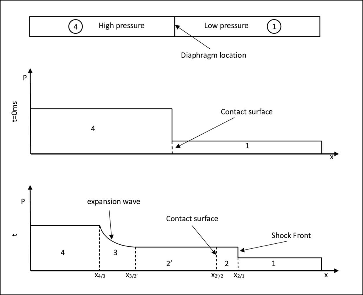
Schematic pressure distribution in the shock tube problem before and after diaphragm removal.
The tube is considered to be sufficiently long to avoid a reflection effect. We also assume that these two regions (two sides separated by the diaphragm) contain the same gas and negligible viscous effects. The fluid is considered as an ideal gas under polytropic transformation and submitted to an expansion, leading to a variable velocity in the space-time (x, t) domain. When assuming the ideal gas assumption, Eq. (1), the Euler formulation can be described by the conservative equation of a variable
where S represents the source term and
The flow vector is given by:
The computation domain is discretized in x
i
intervals (i = 1…N), where
The final equation form at the integration time t = n Δt is:
The previous study has proposed several numerical schemes [21] to predict the shock wave inside the tube shock. The Riemann approximation solution [22,23,24] can be obtained by different schemes like Lax-Wendorf, centered scheme, scheme of decomposition flow, scheme type Riemann solver, and no oscillation scheme.
3 Numerical study of the selected NASA nozzle
Numerical investigations are carried out by considering the experimental study achieved by Hunter [25] on a convergent–divergent of a flat nozzle to simulate the interaction phenomenon of shock waves. The computational domain is a 2D convergent–divergent nozzle with a section ratio of 1.8 and a divergence half-angle of 11.01°. The length of the divergent part L is equal to 0.0577 m, as shown in Figure 2. After validation, the convergent geometry will be changed to study its impact on the detachment of the boundary layers caused by the shock waves in the divergent part.
![Figure 2
Presentation of the NASA nozzle geometry [25].](/document/doi/10.1515/phys-2022-0185/asset/graphic/j_phys-2022-0185_fig_002.jpg)
Presentation of the NASA nozzle geometry [25].
3.1 Nozzle geometry
Several studies [26,27,28,29] showed that the flow in a nozzle subjected to a wave shock is asymmetrical, especially during the starting or at the stop phases. Hence, in this study, the flow is considered symmetric because we are on an established flow regime, and therefore, only the half geometry is represented with the axe of symmetry in 2D space.
3.2 Computational mesh
Several grids are tested to find the best compromise between the accuracy of the results and computational cost. The selected mesh is a structured model with embedded mesh refinement, as shown in Figure 3. The total number of cells is 276,118 cells. It is refined at the throat and walls.
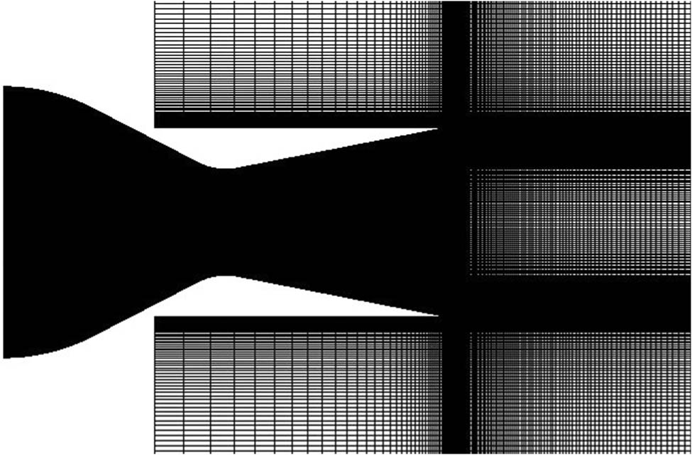
The nozzle structured mesh.
The results are compared with those obtained experimentally by Hunter [25] for different NPRs. Figure 4 shows the results from four meshes compared to the experimental data corresponding to NPR = 3.014. The choice of the mesh depends on the precision with which the boundary layer is processed. The commonly used parameter to evaluate this accuracy is Y+. As shown in Figure 4, the values of Y+ are less than 5 over the entire interaction zone, representing good precision in determining the properties of the boundary layer.

Determination of the best grid mesh for NPR = 3.014 and Y+ (M3 mesh).
3.3 Boundary conditions
The simulations are performed by CONVERGE CFD software. The boundary conditions are illustrated in Figure 5. A pressure inlet boundary condition is imposed at the inlet of the primary nozzle. Another pressure-far-field type is set on the ambient pressure, and a final boundary condition of the pressure outlet is required at the output of the computational domain. The walls of the nozzle are considered adiabatic and symmetry type. These conditions are imposed at the top and the bottom of the computational domain boundaries.

The different boundary conditions.
3.4 Turbulence models
In this study, different NPRs are considered: 2.008, 2.412, 3.014, 3.413, 3.816, 4.217, and 5.018. The experimental work reported in ref. [25] corresponds to NPR = 3.014. The choice of the turbulence model can affect the results significantly. The Reynolds-averaged Navier-Stokes approach is adopted as shown in ref. [30], and two turbulence models have been tested in this study, namely, the standard k−ε and k−ω SST models [31]. The results are qualitatively compared to the Schlieren flow visualization, as shown in Figure 6.

Schlieren flow visualization for NPR = 3.014.
As shown in Figure 7, the Mach disk position is apparent with the k−ω SST model, while for the k−ε model, it is in an external position far from the exit. On the other hand, the k−ω SST model accurately follows the boundary layer separation zone compared to the experimental visualization. Furthermore, Figure 8 illustrates the comparison between experimental and numerical nondimensional parietal static pressure of the nozzle. It shows that the pressure decreases more with the k−ε model than with the k−ω SST model at the separation point and daily of the separation point. Consequently, the k−ω SST model will be used in this study.

Impact of the two turbulence models on the numerical result: (a) k−ε and (b) k−ω shear-stress transport (SST).
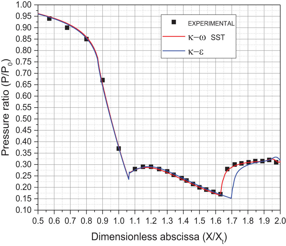
Comparison between the experimental and numerical results of the nozzle parietal static pressure for the two turbulence models.
4 Results and discussion
4.1 Shock tube problem
Ten Fortran programs were used to solve the shock tube problem with 10 different schemes. Reference [21] showed that this problem is numerically sensitive to the selected scheme. Those schemes are tested to choose the best one for describing the shock wave accurately.
They assume that the corresponding ratios are P4/P1 = 10.0, ρ4/ρ1 = 10.0, and T4/T1 = 1.1. The Courant–Friedrichs–Lewy number = 0.8. Air is considered a perfect gas with no viscous effect in the 1D flow.
Figure 9 shows that the schemes artificially upstream flux vector splitting (AUFS), advection upwind splitting method (AUSM), ROE, Steger-Warming, VAN-LEER, and Zha-Bligen are in good agreement with the literature [32,33,34,35,36,37,38,39]. Figure 1 shows that the three main zones are captured: the first zone is where the shock wave propagates from high to low pressure, the second zone is where the relaxation wave propagates from low pressure to high pressure, and the third zone is the isobaric line between these two zones. The other schemes, HLLL, LAX, Rusanove, and Ritchmyer, describe more than two different isobar sliding lines [22,23,24], which is not consistent with the literature.

The shock tube problem resolved using different numerical schemes.
Figure 10 shows for AUSM and Zha-Bilgne schemes, and this evolution presents oscillations at the isobar line, while the ROE, AUFS, and Steger-Warming schemes offer a solution without numerical oscillations. However, the Steger Warming scheme is noticeably more diffusive.

Pressure evolution at isobar line.
4.2 Supersonic NASA nozzle
Figure 11 presents the evolution of the pressure ratio P/P 0 (fraction of the parietal pressure on the generative pressure or pressure inlet), according to the nondimensional distance x/xt with xt in throat abscissa. These results correspond to NPR = 2.412, 3.014, and 3.816. They are compared with the experimental results reported in ref. [25] concerning the same NASA nozzle (NASA Langley Research Center 16-Foot Transonic Tunnel complex). Good agreement has been obtained, and we notice that the numerical simulation captures the location of the boundary layer separation. Figure 12 represents the shock scheme case for NPR = 2.412. Although the angles of incident shock and the reflection shock are mostly well simulated, the normal shock length is underestimated with a relative error of 18% compared to the experimental visualization case.
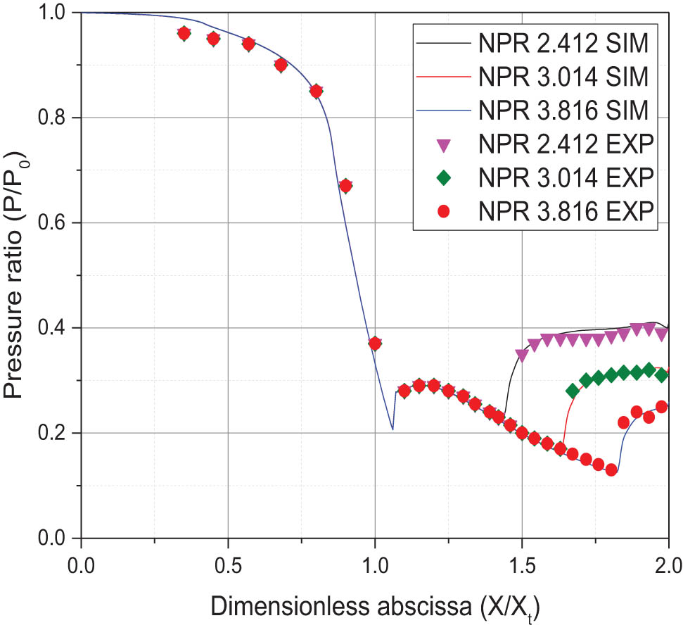
Comparison between numerical and experimental results of parietal static pressures for several NPRs.
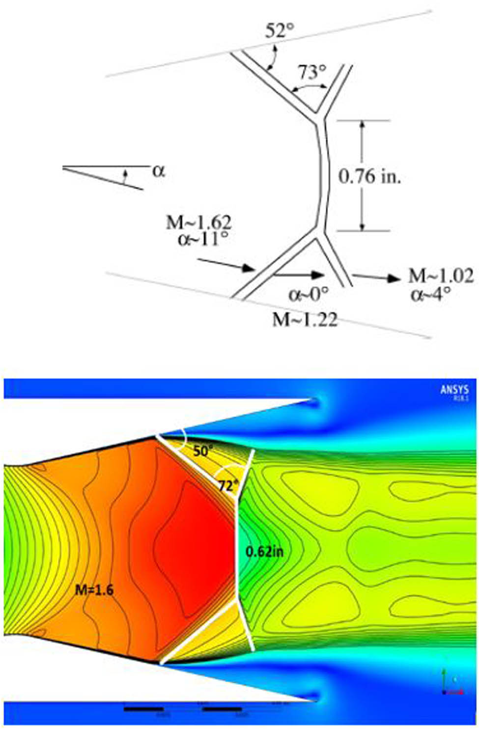
Comparison between numerical and experimental shock scheme for NPR = 2.412.
4.3 Impact of the convergent geometry
Some numerical and experimental investigations are focused on the divergent profile impact on the nozzle flow behavior [20,25,26,27,28,29,30,31,40]. Still, the effect of convergent remains a gap in the current literature. Hence, we carried out numerical investigations to study the impact of the convergent geometry change on the flow, the coordinates location of the boundary layer separation inside the divergent, and the characteristics of the flow. Three different shapes of the convergent are considered: (i) the convex shape corresponding to the studied nozzle (Profile A), (ii) the conical shape (Profile B), and (iii) the concave shape (Profile C). The input and the output sections of the convergent nozzle of NASA Langley Research Center 16-Foot Transonic Tunnel complex are maintained unchanged. Figure 13 shows the geometric profiles of the three considered convergents.
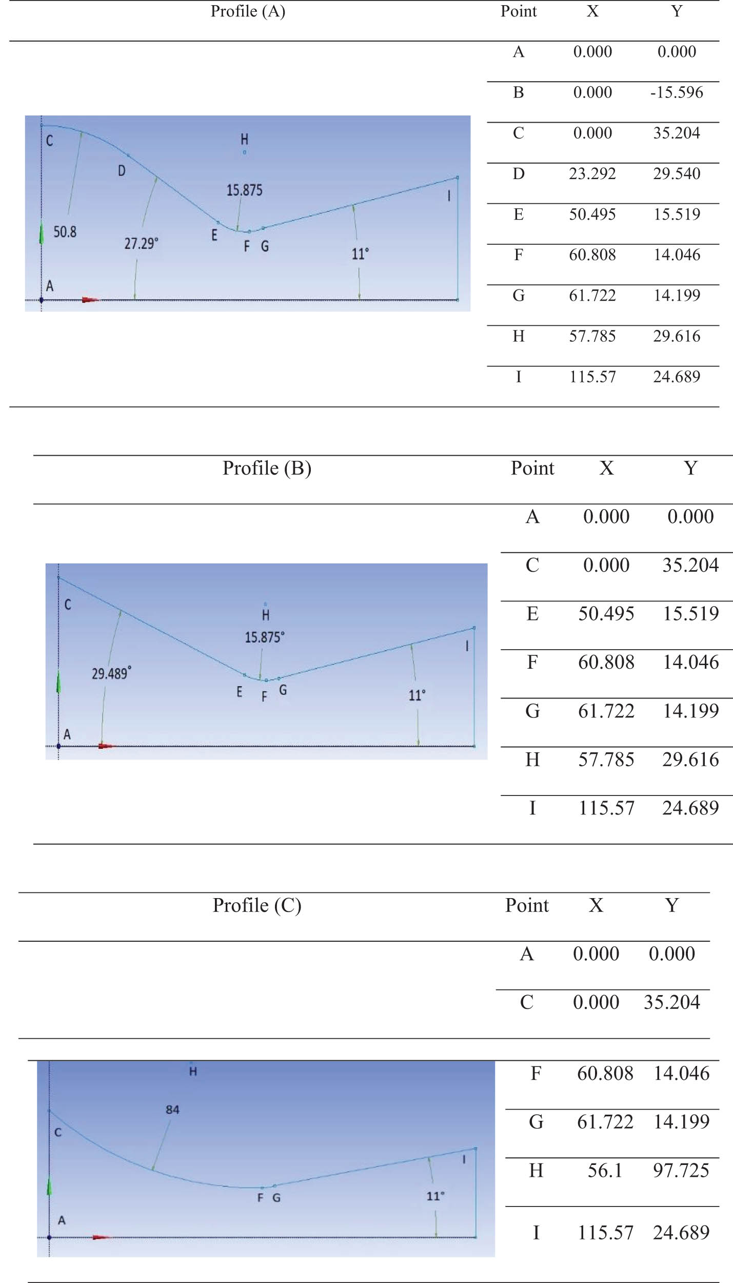
Geometric profile of the three convergent shapes.
Figure 14 illustrates the location of the boundary layer separation for each profile. It shows the effect of changing the convergent geometric profile on the appearance of the boundary layer separation. Seven different NPRs ranging from 2.008 to 5.018 are considered. Profile (A) provides an earlier separation location for all NPR values, followed by profile (B). It can be noticed that profile (C) presents the daily point of separation. This behavior is not changing for all NPRs. It can also be seen that profile (C) illustrates the optimum regime behavior for NPR 5.018, which is not the case for the two other profiles (A) and (B).
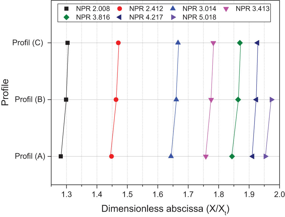
Location of the boundary layer separation for different NPR ratios and convergent profiles.
Figure 15 shows the reached Mach number at the separation section for each profile and each NPR. The results show that the changing of the geometric profile of the convergent influences the Mach number at the separation point called Mach separation. For all NPRs, profile (A) has a lower Mach number than those corresponding to profile (B), and profile (C) provides the higher Mach number separation This difference in Mach number attenuated when the NPR increases and the almost same value was obtained at the NPR 5.018, so it can be noticed that profile (C) offers a higher Mach number than the other profiles, and this comportment does not change for all NPRs.

Mach number at separation point for different NPR ratios and convergent profiles.
Figure 16 illustrates the different pressure separation ratio at various NPRs. It can be noticed that the lower pressure ratio (P sep/P 0) was always generated on profile (C), which is in good agreement with the result shown in Figure 15. Indeed, the pressure decrease causes the velocity to increase and, consequently, increases the Mach number. For all NPRs, profile (A) has a higher-pressure separation ratio than other profiles (B) and (C). But almost the same results were noticed at NPR 5.018 for (A) and (B). For profile (C), the nozzle is in the optimum regime.
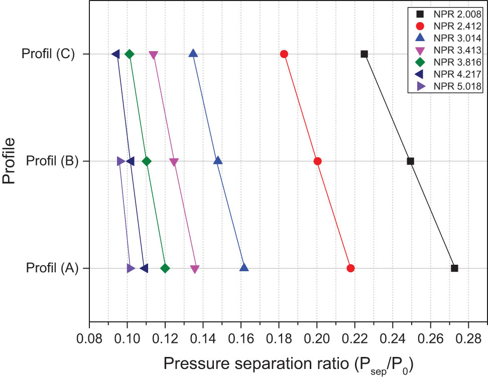
Pressure ratio at the separation point for different NPR and convergent profiles.
Figure 17 describes the axial evolution of the pressure ratio P/P 0 according to the nondimensional abscissa x/xt. The examination of these curves shows that in graph (a), the pressure curve corresponding to profile (C) decreases more rapidly (strong expansion) between the inlet of the convergent and the throat section than in the other profiles. This effect is due to the impact of the convergent profile, imposing the intensity to decrease along the abscissa x. For graph (b), the shock wave of profile (C), which recompresses the flow outside the nozzle, is 5% higher than the other profiles. However, the shock wave location is different for each convergent profile. Figure 18 describes the pressure ratio P/P 0 close to the wall according to the nondimensional abscissa x/xt. Similarly, this parietal pressure ratio decreases strongly for profile (C) according to the reduced abscissa x/xt. The ratio P/P 0 is the same at the throat section for all the profiles (sonic wall).
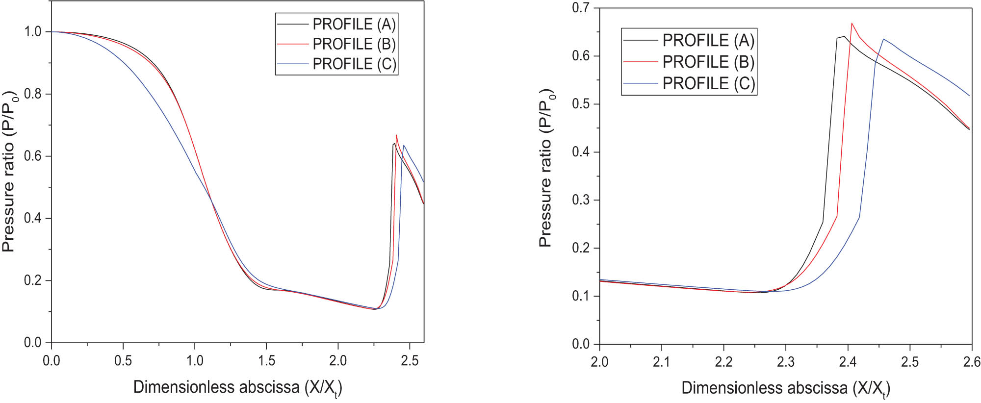
Axial pressure ratio P/P 0 along with the nozzle for different convergent profiles at NPR = 3.816.
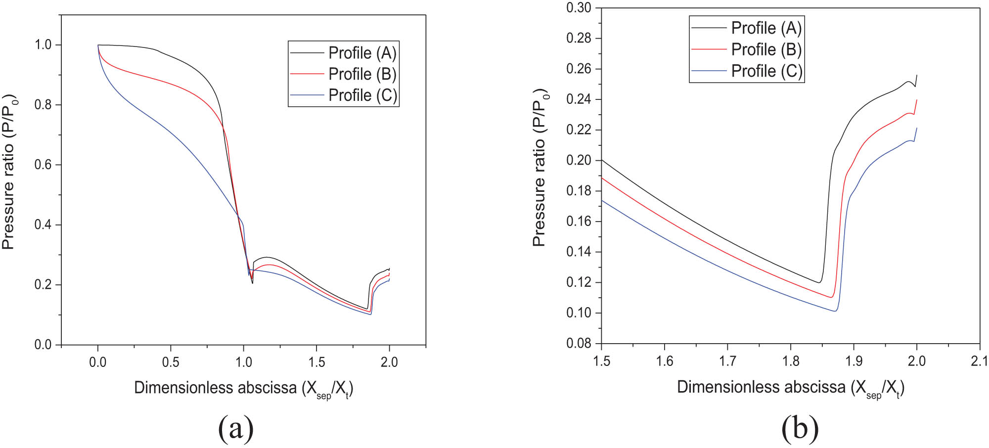
Wall pressure ratio P/P 0 along with the nozzle for different convergent profiles at NPR = 3.816. (a) The evolution of the pressure along the wall of the nozzle and (b) the evolution of the pressure at the separation zone on the wall of the nozzle.
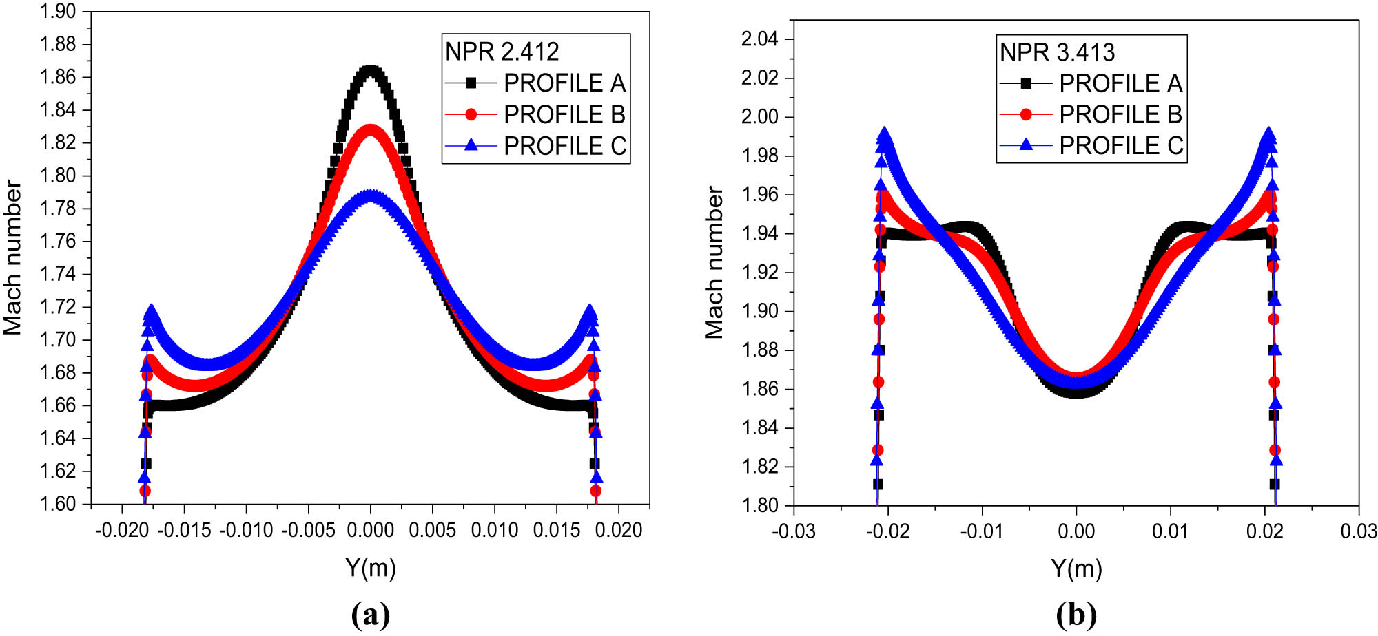
Figure 19 shows the difference between Mach number profiles at the throat section for different NPR and three different convergent profiles. It can be noticed that at the low NPR of 2.008, profiles (A) and (B) are mostly superimposed, and profile (C) is relatively different. The Mach gradient in this section (difference between the highest value and the lower value of Mach) is more important in the case of profiles (A) and (B) with Δ Mach number = 0.4. While for profile (C), Δ Mach number = 0.2. Also, for a higher NPR, Mach number = 3.413. This behavior is confirmed, and the distinction between profiles (A) and (B) are noticed but with the same gradient Δ Mach number = 0.4. For profile (C), Δ Mach number = 0.15, the velocity profile is one of the conditions that create different flow behavior at the downstream (divergent) for different profiles of convergent. At the same time, the Mach number near a wall is always higher in the case of profile (A) followed by (B) and profile (C), and that is true for all NPR. But, at the axis of the flow (axis of the nozzle), the Mach number at profile (C) is higher than profile (A) et (B). This behavior and tendency are reversed in the separation section, as shown in Figure 20, although for profile (C). The distribution of the Mach number is smooth or with a low gradient Δ Mach number. This behavior should result from the quasi-linear acceleration in the convergent, as shown in Figures 17, 18 and 21.

Comparison between the Mach number profile at the throat section for (a) NPR = 2.412 and (b) NPR = 3.413 of different profiles.
Comparison between the Mach number profile at the separation section for (a) NPR = 2.412 and (b) NPR = 3.413 for different profiles.

Evolution of the Mach number in the convergent for NPR 2.008.
Figure 21 shows the Mach number evolution near the wall (at 1 mm) and at the axis of symmetry for different profiles (A), (B), and (C) for NPR = 2.008. It is noticed that the acceleration in the convergent follows a different curve for different profiles of convergent geometric. Also, profile (C) allows an almost linear acceleration, unlike profiles (A) and (B). This behavior can explain why the profile of Mach number downstream before separation is more uniform and smoother than the two other profiles (A) and (B).
The recirculation zone located downstream of the separation point results from the reintroduction of ambient air inside the nozzle. Figure 22 illustrates the difference between the recirculation zones for the different profiles at NPR = 3.413. It can be seen clearly that profile (A) induced the largest vortex (+40% compared to profile (B) and +60% compared to profile (C)), given the problems that can be generated by this phenomenon such as the lateral load (side-load). It is very important to understand that the change in the convergent profile can influence the vortex intensity of the recirculation zone.
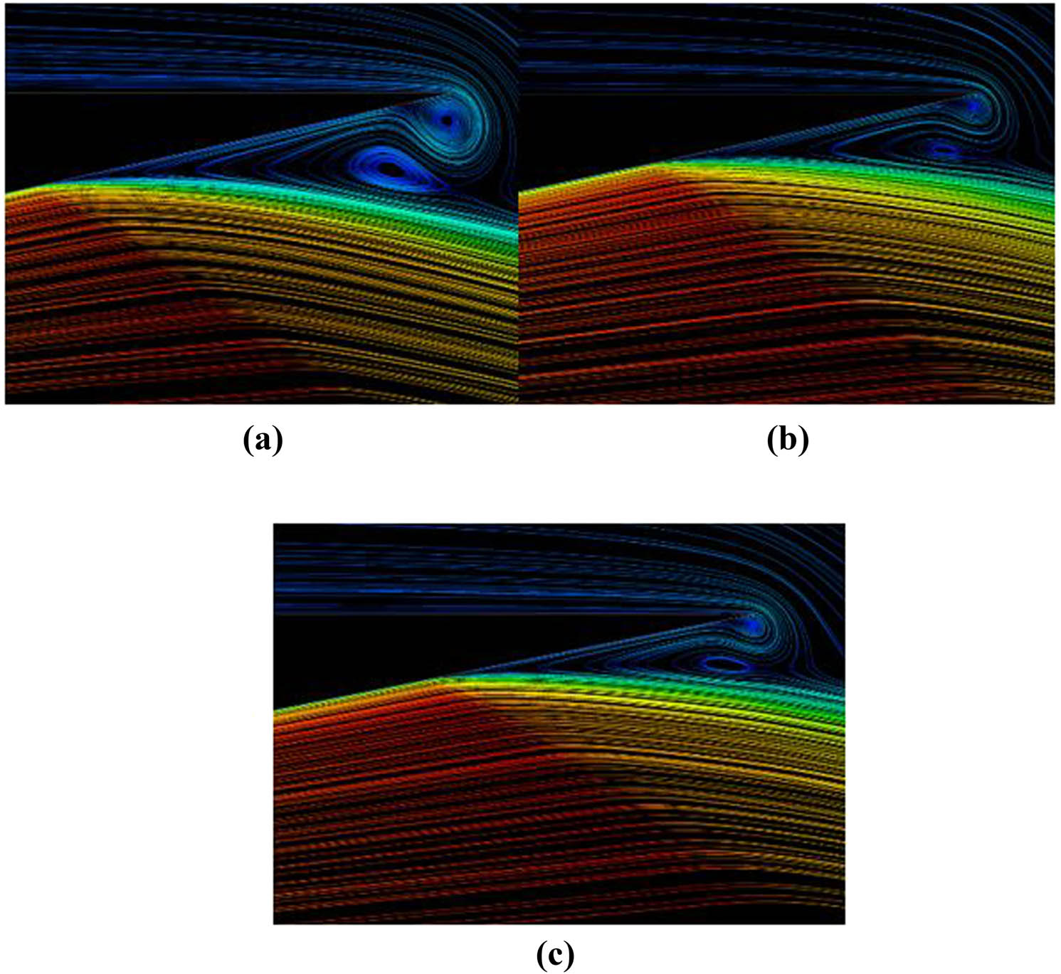
Recirculation zone for profiles a, b and c at NPR = 3.413.
Figure 23 illustrates the effect of changing the convergent geometric profiles on the Mach number, the wall pressure ratio P/P 0, and the location of the separation of the boundary layer for different NPR values. This figure allows better distinguishing the difference between the three studied convergent profiles and observing each profile’s behavior for different NPR values. For all NPR values, profile (C) depicts the lowest wall pressure ratio at the point of boundary layer separation. Consequently, it presents the highest resistance to separation than the other profiles and develops a higher Mach number for all NPRs of this study.

Effect of the convergent geometric profiles on the Mach number, the wall pressure, and the location of the boundary layer separation.
For the other two profiles, profile (B) resists the separation relatively more than profile (A) for all NPRs significantly beyond 3.413.
The insert of the obtained results in Figure 24 shows that the three studied profiles follow the resulting tendency found by previous researchers summarized by Stark [40], but only for the NPR from 2.008 to 3.816 (delimited in the figure by the rectangle). It should be noted that the three profiles follow the Schmucker separation criteria Eq. (7). However, it should also be noted that apparently, the Schmucker criteria do not consider the difference induced by the different geometries of the convergent. Still, it is also unable to describe the evolution of P sep/P a as a function of M sep for NPR 1.608 and NPR 4.217 at 5.018. For these NPR, the separation is close either to the throat or to the outlet lip of the nozzle. The influence of this cretic location makes the relation P sep/P a a function of M sep obsolete. Figure 23, which is described by a relation P sep/P 0 according to M sep, which describes this evolution well whatever the number of NPR, it also describes the difference of changes in the convergent geometry.

Separation database.
The thrust efficiency results are shown in Figure 25. The measured thrust ratio F/F i [41] is plotted and compared with the three curves resulting from the numerical simulation of the three different convergent profiles (A)–(C). The analysis shows that the curves of Figure 25 show that the results of Cf resulting from the simulation follow the experimental results well. This figure also shows that the change in the convergent profile affects the thrust efficiency. We notice that for NPR = 5.016, the three curves of the numerical simulation almost coincide. This NPR represents the optimum regime case, where the separation of the boundary layer is at the nozzle exit lip. For lower NPRs, the curves separate gradually. But, still following the experimental curve tendency, for an NPR of 3.014, profile (C) develops a F/F i higher than profile (A) by 5%.
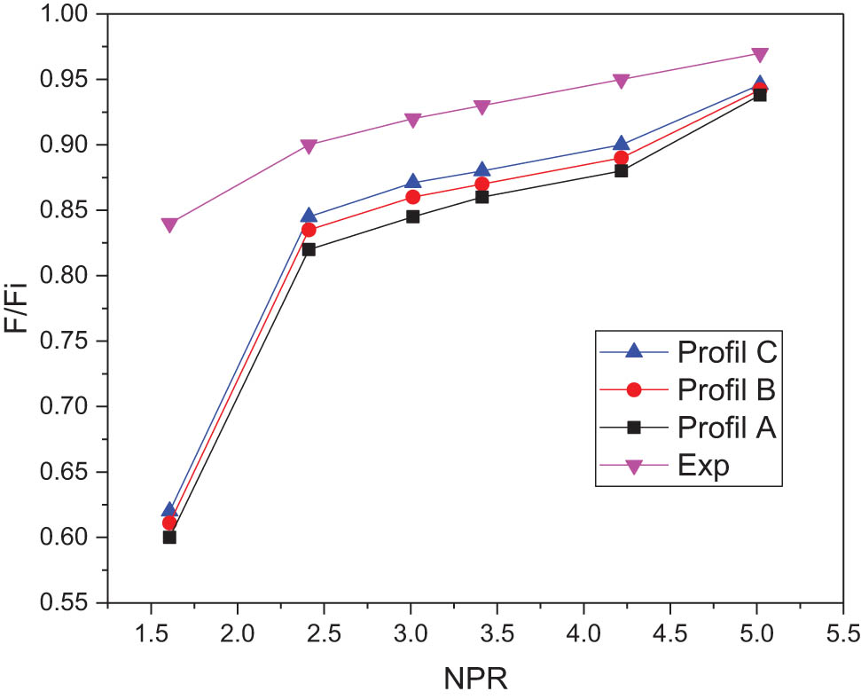
Experimental and numerical thrust efficiency for different profiles and NPR.
5 Conclusion
This work investigated the impact of changes in the convergent geometry profile on the boundary layer separation in an overextended supersonic nozzle numerically. The ROE numerical flow scheme has better predicted the shock wave phenomenon. The following conclusions are drawn from the obtained results.
The convergent geometric profile of the nozzle impacts the localization of the boundary layer separation and the shock wave because it modifies the profile of velocity and pressure at the throat section.
The changes in pressure and temperature fields are also due to the convergent geometry change, thus affecting the kinetic energy repartition, potential energy, and the intensity of the Mach, and creating the difference in locations of the boundary layer separation.
The profiles were adapted well to the Schmucker criterion for NPR, where the separation is far from the exit lip.
The curve of P/P 0 = f(M sep) can give a better criterion. The convergent geometry also influences trust efficiency.
As a recommendation, the geometrical optimization of the nozzles operating in an overextended regime must consider the appropriate geometric profile of the convergent and its impact on the flow behavior.
For future work, our approach will be based on two main objectives:
To investigate the optimal convergent geometry profile for nozzle,
to expand the simulations on other cases to obtain the maximum data to develop a new boundary layer separation criterion that takes into account the change in the profile of the convergent.
Acknowledgments
The authors wish to express their deep consideration to Convergent Science (USA) team for their cooperation and assistance.
-
Funding information: The authors state no funding involved.
-
Author contributions: All authors have accepted responsibility for the entire content of this manuscript and approved its submission.
-
Conflict of interest: The authors state no conflict of interest.
References
[1] Assonitis A, Paciorri R, Bonfiglioli A. Numerical simulation of shock boundary layer interaction using shock fitting technique. Conference of the Italian Association of Theoretical and Applied Mechanics. Springer; 2019. p. 124–34.10.23967/wccm-eccomas.2020.243Suche in Google Scholar
[2] Das BD, Sardar R, Sarkar S, Manna NK, editors. Compressible flow through convergent–divergent nozzle. Singapore: Springer Singapore; 2021.10.1007/978-981-33-4165-4_32Suche in Google Scholar
[3] Zhang Y, Ma Z, Zou J, Zheng Y, editors. Shock bifurcation phenomenon in the reflected shock/boundary layer interaction. Singapore: Springer Singapore; 2019.10.1007/978-981-13-3305-7_34Suche in Google Scholar
[4] Matheson MA, Grosvenor AD, Zheltovodov AA. Shock wave/turbulent boundary layer interactions. Proceedings of the 2011 companion on High Performance Computing Networking, Storage and Analysis Companion. Seattle, Washington, USA: Association for Computing Machinery; 2011. p. 131–2.10.1145/2148600.2148669Suche in Google Scholar
[5] Lee C, Choi K, Kim C, Han S. Computational investigation of flow separation in a thrust-optimized parabolic nozzle during high-altitude testing. Comput Fluids. 2020;197:104363.10.1016/j.compfluid.2019.104363Suche in Google Scholar
[6] Goncalves E, Lehnasch BG, Herpe CJ, editors. Hybrid RANS/LES Simulation of Shock-Induced Separated Flow in Truncated Ideal Contour Nozzle. 31st International Symposium on Shock Waves 2 ISSW 2017 Springer. Cham: Springer International Publishing; 2019.10.1007/978-3-319-91017-8_65Suche in Google Scholar
[7] Li Y, He C, Li J, Miao L, Gao R, Liang J. Experimental investigation of flow separation in a planar convergent-divergent nozzle. Phys: Conf Ser. 2019;1300(1):012088.10.1088/1742-6596/1300/1/012088Suche in Google Scholar
[8] Wang YS, Xu JL, Huang S, Lin YC, Jiang JJ. Experimental and numerical investigation of an axisymmetric divergent dual throat nozzle. Part G: J Aerosp Eng. 2020;234(3):563–72.10.1177/0954410019872089Suche in Google Scholar
[9] Léger L, Zmijanovic V, Sellam M, Chpoun A. Experimental investigation of forced flow regime transition in a dual bell nozzle by secondary fluidic injection. Int J Heat Fluid Flow. 2021;89:108818.10.1016/j.ijheatfluidflow.2021.108818Suche in Google Scholar
[10] Zebiri B, Piquet A, Hadjadj A, Verma S. Shock-induced flow separation in an overexpanded supersonic planar nozzle. AIAA J. 2020;58(5):2122–31.10.2514/1.J058705Suche in Google Scholar
[11] Vaisakh S, Muruganandam T. Visualization of over-expanded supersonic wall-jet. Aerosp Sci Technol. 2021;112:106617.10.1016/j.ast.2021.106617Suche in Google Scholar
[12] Verma SB, Manisankar C. Origin of flow asymmetry in planar nozzles with separation. Shock Waves. 2014;24(2):191–209.10.1007/s00193-013-0492-1Suche in Google Scholar
[13] Yu Y. Over-expanded separation transitions of single expansion ramp nozzle in the accelerating and decelerating processes. Aerosp Sci Technol. 2020;98:105674.10.1016/j.ast.2019.105674Suche in Google Scholar
[14] Martelli E, Saccoccio L, Ciottoli P, Tinney C, Baars W, Bernardini M. Flow dynamics and wall-pressure signatures in a high-Reynolds-number overexpanded nozzle with free shock separation. J Fluid Mech. 2020;895:A29. 10.1017/jfm.2020.280.Suche in Google Scholar
[15] Ivanov I, Kryukov I. Numerical study of ways to prevent side loads in an over–expanded rocket nozzles during the launch stage. Acta Astronaut. 2019;163:196–201.10.1016/j.actaastro.2019.02.032Suche in Google Scholar
[16] Papamoschou D, Zill A, Johnson A. Supersonic flow separation in planar nozzles. Shock Waves Springer. 2009;19(3):171.10.1007/s00193-008-0160-zSuche in Google Scholar
[17] Gouidmi H, Beghidja A, Benderradji R. Etude numérique d’une structure de choc Phénomène d’interaction choc/couche limite. Rev des Energ Renouvelables. 2017;20(3):397–413.10.54966/jreen.v20i3.636Suche in Google Scholar
[18] Quadros R, Bernardini M. Numerical investigation of transitional shock-wave/boundary-layer interaction in supersonic regime. AIAA. 2018;56(7):2712–24.10.2514/1.J056650Suche in Google Scholar
[19] Meister L, Burtschell Y, Zeitoun DE. Numerical study of a reactive flow in an over-expanded nozzle: influence of wall temperature and altitude. Méc Ind. 2003;4(4):339–46.10.1007/978-3-540-27009-6_183Suche in Google Scholar
[20] Genin C, Stark R. Side loads in subscale dual bell nozzles. Propuls Power AIAA. 2011;27(4):828–37.10.2514/1.B34170Suche in Google Scholar
[21] Masatsuka K. I, do Like CFD. Vol. 1. Lulu. com; 2013.Suche in Google Scholar
[22] Erturk V, Godwe E, Baleanu D, Kumar P, Asad J, Jajarmi A. Novel fractional-order lagrangian to describe motion of beam on nanowire. Acta Phys Polon A. 2021;140(3):265–72.10.12693/APhysPolA.140.265Suche in Google Scholar
[23] Jajarmi A, Baleanu D, Vahid KZ, Pirouz HM, Asad J. A new and general fractional Lagrangian approach: a capacitor microphone case study. Results Phys. 2021;31:104950.10.1016/j.rinp.2021.104950Suche in Google Scholar
[24] Soomro A, Qureshi S, Shaikh AA. A New Nonlinear Hybrid Technique with fixed and adaptive step-size approaches. Sigma J Eng Nat Sci. 2022;40(1):162–78.10.14744/sigma.2022.00013Suche in Google Scholar
[25] Hunter CA. Experimental investigation of separated nozzle flows. Propuls Power AIAA. 2004;20(3):527–32.10.2514/1.4612Suche in Google Scholar
[26] Xiao Q, Tsai H-M, Papamoschou D. Numerical investigation of supersonic nozzle flow separation. AIAA. 2007;45(3):532–41.10.2514/1.20073Suche in Google Scholar
[27] Shigeru M, Kousuke K, Junji N, Md Tawhidul Islam K, Toshiaki S, Heuy Dong K. Effects of supersonic nozzle geometry on characteristics of shock wave structure. Open J Fluid Dyn. 2012;2012:181–6.10.4236/ojfd.2012.24A019Suche in Google Scholar
[28] Östlund J, Damgaard T, Frey M. Side-load phenomena in highly overexpanded rocket nozzles. Propuls Power AIAA. 2014;20(4):695–704.10.2514/1.3059Suche in Google Scholar
[29] Abdol-Hamid KS, Hunter CA. Numerical investigation of flow in an overexpanded nozzle with porous surfaces. Aircraft. 2006;43(4):1217–25.10.2514/1.18835Suche in Google Scholar
[30] Asproulias I, Revell A, Craft T, editors. Modelling shock wave/boundary layer interactions using advanced RANS models. International Symposium on Shock Waves Springr. Springer; 2015.10.1007/978-3-319-16838-8_71Suche in Google Scholar
[31] Menter F. Zonal two equation kw turbulence models for aerodynamic flows. American Institute of Aeronautics and Astronautics AIAA; 1993. p. 1–21.10.2514/6.1993-2906Suche in Google Scholar
[32] Hadjadj A. Analyse physique et simulation numérique des écoulements compressibles. Application aux tuyères de propulseurs: Universite de Rouen; 1997. p. 82.Suche in Google Scholar
[33] Houas L, editor. Ten Years of shock tube research at Marseille. International Symposium on Shock Waves. Springer; 2013. p. 11–8.10.1007/978-3-319-16835-7_2Suche in Google Scholar
[34] Aune V, Fagerholt E, Langseth M, Børvik T. A shock tube facility to generate blast loading on structures. Int J Protect Struct. 2016;7(3):340–66.10.1177/2041419616666236Suche in Google Scholar
[35] Dewey JM. Explosive flows: shock tubes and blast waves. Handbook of flow visualization. Routledge; 2018. p. 495.10.1201/9780203752876-31Suche in Google Scholar
[36] Zhai Z, Zou L, Wu Q, Luo X. Review of experimental Richtmyer–Meshkov instability in shock tube: from simple to complex. Mech Eng Sci. 2018;232(16):2830–49.10.1177/0954406217727305Suche in Google Scholar
[37] Kiverin A, Yakovenko I. Ignition and detonation onset behind incident shock wave in the shock tube. Combust Flame. 2019;204:227–36.10.1016/j.combustflame.2019.03.012Suche in Google Scholar
[38] Nativel D, Cooper SP, Lipkowicz T, Fikri M, Petersen EL, Schulz C. Impact of shock-tube facility-dependent effects on incident-and reflected-shock conditions over a wide range of pressures and Mach numbers. Combust Flame. 2020;217:200–11.10.1016/j.combustflame.2020.03.023Suche in Google Scholar
[39] Sembian S, Liverts M. On using converging shock waves for pressure amplification in shock tubes. Metrologia. 2020;57:035008.10.1088/1681-7575/ab7f99Suche in Google Scholar
[40] Stark R, editor. Flow separation in rocket nozzles, a simple criteria. 41st AIAA/ASME/SAE/ASEE Joint Propulsion Conference & Exhibit; 2005.10.2514/6.2005-3940Suche in Google Scholar
[41] Hunter CA. An approximate theoretical method for modeling the static thrust performance of non-axisymmetric two-dimensional convergent-divergent nozzles. George Washington University; 1995. p. 32.Suche in Google Scholar
© 2022 Rabie Dehane et al., published by De Gruyter
This work is licensed under the Creative Commons Attribution 4.0 International License.
Artikel in diesem Heft
- Regular Articles
- Test influence of screen thickness on double-N six-light-screen sky screen target
- Analysis on the speed properties of the shock wave in light curtain
- Abundant accurate analytical and semi-analytical solutions of the positive Gardner–Kadomtsev–Petviashvili equation
- Measured distribution of cloud chamber tracks from radioactive decay: A new empirical approach to investigating the quantum measurement problem
- Nuclear radiation detection based on the convolutional neural network under public surveillance scenarios
- Effect of process parameters on density and mechanical behaviour of a selective laser melted 17-4PH stainless steel alloy
- Performance evaluation of self-mixing interferometer with the ceramic type piezoelectric accelerometers
- Effect of geometry error on the non-Newtonian flow in the ceramic microchannel molded by SLA
- Numerical investigation of ozone decomposition by self-excited oscillation cavitation jet
- Modeling electrostatic potential in FDSOI MOSFETS: An approach based on homotopy perturbations
- Modeling analysis of microenvironment of 3D cell mechanics based on machine vision
- Numerical solution for two-dimensional partial differential equations using SM’s method
- Multiple velocity composition in the standard synchronization
- Electroosmotic flow for Eyring fluid with Navier slip boundary condition under high zeta potential in a parallel microchannel
- Soliton solutions of Calogero–Degasperis–Fokas dynamical equation via modified mathematical methods
- Performance evaluation of a high-performance offshore cementing wastes accelerating agent
- Sapphire irradiation by phosphorus as an approach to improve its optical properties
- A physical model for calculating cementing quality based on the XGboost algorithm
- Experimental investigation and numerical analysis of stress concentration distribution at the typical slots for stiffeners
- An analytical model for solute transport from blood to tissue
- Finite-size effects in one-dimensional Bose–Einstein condensation of photons
- Drying kinetics of Pleurotus eryngii slices during hot air drying
- Computer-aided measurement technology for Cu2ZnSnS4 thin-film solar cell characteristics
- QCD phase diagram in a finite volume in the PNJL model
- Study on abundant analytical solutions of the new coupled Konno–Oono equation in the magnetic field
- Experimental analysis of a laser beam propagating in angular turbulence
- Numerical investigation of heat transfer in the nanofluids under the impact of length and radius of carbon nanotubes
- Multiple rogue wave solutions of a generalized (3+1)-dimensional variable-coefficient Kadomtsev--Petviashvili equation
- Optical properties and thermal stability of the H+-implanted Dy3+/Tm3+-codoped GeS2–Ga2S3–PbI2 chalcohalide glass waveguide
- Nonlinear dynamics for different nonautonomous wave structure solutions
- Numerical analysis of bioconvection-MHD flow of Williamson nanofluid with gyrotactic microbes and thermal radiation: New iterative method
- Modeling extreme value data with an upside down bathtub-shaped failure rate model
- Abundant optical soliton structures to the Fokas system arising in monomode optical fibers
- Analysis of the partially ionized kerosene oil-based ternary nanofluid flow over a convectively heated rotating surface
- Multiple-scale analysis of the parametric-driven sine-Gordon equation with phase shifts
- Magnetofluid unsteady electroosmotic flow of Jeffrey fluid at high zeta potential in parallel microchannels
- Effect of plasma-activated water on microbial quality and physicochemical properties of fresh beef
- The finite element modeling of the impacting process of hard particles on pump components
- Analysis of respiratory mechanics models with different kernels
- Extended warranty decision model of failure dependence wind turbine system based on cost-effectiveness analysis
- Breather wave and double-periodic soliton solutions for a (2+1)-dimensional generalized Hirota–Satsuma–Ito equation
- First-principle calculation of electronic structure and optical properties of (P, Ga, P–Ga) doped graphene
- Numerical simulation of nanofluid flow between two parallel disks using 3-stage Lobatto III-A formula
- Optimization method for detection a flying bullet
- Angle error control model of laser profilometer contact measurement
- Numerical study on flue gas–liquid flow with side-entering mixing
- Travelling waves solutions of the KP equation in weakly dispersive media
- Characterization of damage morphology of structural SiO2 film induced by nanosecond pulsed laser
- A study of generalized hypergeometric Matrix functions via two-parameter Mittag–Leffler matrix function
- Study of the length and influencing factors of air plasma ignition time
- Analysis of parametric effects in the wave profile of the variant Boussinesq equation through two analytical approaches
- The nonlinear vibration and dispersive wave systems with extended homoclinic breather wave solutions
- Generalized notion of integral inequalities of variables
- The seasonal variation in the polarization (Ex/Ey) of the characteristic wave in ionosphere plasma
- Impact of COVID 19 on the demand for an inventory model under preservation technology and advance payment facility
- Approximate solution of linear integral equations by Taylor ordering method: Applied mathematical approach
- Exploring the new optical solitons to the time-fractional integrable generalized (2+1)-dimensional nonlinear Schrödinger system via three different methods
- Irreversibility analysis in time-dependent Darcy–Forchheimer flow of viscous fluid with diffusion-thermo and thermo-diffusion effects
- Double diffusion in a combined cavity occupied by a nanofluid and heterogeneous porous media
- NTIM solution of the fractional order parabolic partial differential equations
- Jointly Rayleigh lifetime products in the presence of competing risks model
- Abundant exact solutions of higher-order dispersion variable coefficient KdV equation
- Laser cutting tobacco slice experiment: Effects of cutting power and cutting speed
- Performance evaluation of common-aperture visible and long-wave infrared imaging system based on a comprehensive resolution
- Diesel engine small-sample transfer learning fault diagnosis algorithm based on STFT time–frequency image and hyperparameter autonomous optimization deep convolutional network improved by PSO–GWO–BPNN surrogate model
- Analyses of electrokinetic energy conversion for periodic electromagnetohydrodynamic (EMHD) nanofluid through the rectangular microchannel under the Hall effects
- Propagation properties of cosh-Airy beams in an inhomogeneous medium with Gaussian PT-symmetric potentials
- Dynamics investigation on a Kadomtsev–Petviashvili equation with variable coefficients
- Study on fine characterization and reconstruction modeling of porous media based on spatially-resolved nuclear magnetic resonance technology
- Optimal block replacement policy for two-dimensional products considering imperfect maintenance with improved Salp swarm algorithm
- A hybrid forecasting model based on the group method of data handling and wavelet decomposition for monthly rivers streamflow data sets
- Hybrid pencil beam model based on photon characteristic line algorithm for lung radiotherapy in small fields
- Surface waves on a coated incompressible elastic half-space
- Radiation dose measurement on bone scintigraphy and planning clinical management
- Lie symmetry analysis for generalized short pulse equation
- Spectroscopic characteristics and dissociation of nitrogen trifluoride under external electric fields: Theoretical study
- Cross electromagnetic nanofluid flow examination with infinite shear rate viscosity and melting heat through Skan-Falkner wedge
- Convection heat–mass transfer of generalized Maxwell fluid with radiation effect, exponential heating, and chemical reaction using fractional Caputo–Fabrizio derivatives
- Weak nonlinear analysis of nanofluid convection with g-jitter using the Ginzburg--Landau model
- Strip waveguides in Yb3+-doped silicate glass formed by combination of He+ ion implantation and precise ultrashort pulse laser ablation
- Best selected forecasting models for COVID-19 pandemic
- Research on attenuation motion test at oblique incidence based on double-N six-light-screen system
- Review Articles
- Progress in epitaxial growth of stanene
- Review and validation of photovoltaic solar simulation tools/software based on case study
- Brief Report
- The Debye–Scherrer technique – rapid detection for applications
- Rapid Communication
- Radial oscillations of an electron in a Coulomb attracting field
- Special Issue on Novel Numerical and Analytical Techniques for Fractional Nonlinear Schrodinger Type - Part II
- The exact solutions of the stochastic fractional-space Allen–Cahn equation
- Propagation of some new traveling wave patterns of the double dispersive equation
- A new modified technique to study the dynamics of fractional hyperbolic-telegraph equations
- An orthotropic thermo-viscoelastic infinite medium with a cylindrical cavity of temperature dependent properties via MGT thermoelasticity
- Modeling of hepatitis B epidemic model with fractional operator
- Special Issue on Transport phenomena and thermal analysis in micro/nano-scale structure surfaces - Part III
- Investigation of effective thermal conductivity of SiC foam ceramics with various pore densities
- Nonlocal magneto-thermoelastic infinite half-space due to a periodically varying heat flow under Caputo–Fabrizio fractional derivative heat equation
- The flow and heat transfer characteristics of DPF porous media with different structures based on LBM
- Homotopy analysis method with application to thin-film flow of couple stress fluid through a vertical cylinder
- Special Issue on Advanced Topics on the Modelling and Assessment of Complicated Physical Phenomena - Part II
- Asymptotic analysis of hepatitis B epidemic model using Caputo Fabrizio fractional operator
- Influence of chemical reaction on MHD Newtonian fluid flow on vertical plate in porous medium in conjunction with thermal radiation
- Structure of analytical ion-acoustic solitary wave solutions for the dynamical system of nonlinear wave propagation
- Evaluation of ESBL resistance dynamics in Escherichia coli isolates by mathematical modeling
- On theoretical analysis of nonlinear fractional order partial Benney equations under nonsingular kernel
- The solutions of nonlinear fractional partial differential equations by using a novel technique
- Modelling and graphing the Wi-Fi wave field using the shape function
- Generalized invexity and duality in multiobjective variational problems involving non-singular fractional derivative
- Impact of the convergent geometric profile on boundary layer separation in the supersonic over-expanded nozzle
- Variable stepsize construction of a two-step optimized hybrid block method with relative stability
- Thermal transport with nanoparticles of fractional Oldroyd-B fluid under the effects of magnetic field, radiations, and viscous dissipation: Entropy generation; via finite difference method
- Special Issue on Advanced Energy Materials - Part I
- Voltage regulation and power-saving method of asynchronous motor based on fuzzy control theory
- The structure design of mobile charging piles
- Analysis and modeling of pitaya slices in a heat pump drying system
- Design of pulse laser high-precision ranging algorithm under low signal-to-noise ratio
- Special Issue on Geological Modeling and Geospatial Data Analysis
- Determination of luminescent characteristics of organometallic complex in land and coal mining
- InSAR terrain mapping error sources based on satellite interferometry