Compressive behavior of BFRP-confined ceramsite concrete: An experimental study and stress–strain model
-
Hongchun Li
 ,
Yirui Zhang
,
Yirui Zhang

Abstract
The novel structure of a basalt fiber reinforced polymer (BFRP)-confined ceramsite concrete column (BFCCC) reinforced with bamboo strips (BSs) was investigated. The characteristics of light weight, BSs and FRP reinforcement were reflected in the structure. Thirty-six BFCCCs and 18 unconfined ceramsite concrete columns were fabricated and subjected to axial compression tests, and the stress–strain curves were obtained. The research parameters included the number of BFRP layers and the volume content of BSs. Both types of specimens, with and without BFRP confinement, underwent brittle failure after reaching the ultimate bearing capacity. The increase in the number of BFRP layers had a positive effect on the bearing capacity and deformation capacity of the specimens. With the increase in the number of BFRP layers, the compressive strengths of BFCCCs were improved by 1.17–1.44 times, and the deformations were improved by 6.30–12.92 times, compared to the unconfined concrete. The addition of BSs could improve the ductility of the specimen, while the effect on the bearing capacity had an optimal value of 2.0%. The stress–strain curves of the BFCCCs showed obvious softening behavior after the peak point. Models were proposed to predict the axial stress–strain curves of BFCCCs reinforced with BSs.
Nomenclature
- Parameter
-
Definition
- f l
-
lateral confinement force of FRP
- f co
-
peak stress of unconfined concrete
- f c1
-
peak stress of FRP-confined concrete
- f c2
-
stress at the lowest point after the peak point
- f cu
-
ultimate stress of FRP-confined concrete
- ε co
-
peak strain of unconfined concrete
- ε c1
-
peak strain of FRP-confined concrete
- ε cu
-
ultimate strain of FRP-confined concrete
- ε c2
-
strain at the lowest point after the peak point
- P c1
-
peak load of the specimen
- P cu
-
ultimate load of the specimen
- t f
-
total thickness of FRP
- d
-
diameter of core concrete
- E l
-
lateral confinement stiffness of FRP
- E f
-
elastic modulus of FRP
- E co
-
elastic modulus of unconfined concrete
- f′ cc
-
peak strength of FRP-confined concrete
- f f
-
ultimate tensile stress of FRP standard specimen
- f 30
-
strength of unconfined C30 concrete
- ε f
-
ultimate tensile strain of FRP standard specimen
- Δf l
-
increment of lateral confinement
- Δε r
-
increment of lateral strain
- ε h,rup
-
lateral fracture strain of FRP
1 Introduction
With the continuous development of society, engineers are developing buildings in the direction of super high-rise and large span structures and proposing more demanding requirements for self-weight, strength, and toughness of concrete. Compared to normal concrete with the same strength grade, lightweight aggregate concrete (LWAC) can reduce weight by 20–40% and has the advantages of good impermeability, good durability and seismic resistance, thermal insulation and green environmental protection [1], and thus it has been more widely used in construction projects [2,3]. Ceramsite concrete is a commonly used LWAC prepared by replacing a certain proportion of coarse aggregate with ceramsite and then combining the mixture with cementing materials, admixtures, and water [4]. However, the elastic modulus of ceramsite concrete is low, and the common aggregates of ceramsite concrete, such as shale ceramsite [5,6], clay ceramsite [7], and fly ash ceramsite [8], are lightweight and low density. Due to the low strength and porosity of aggregate, cracks can penetrate ceramsite aggregate during failure, resulting in greater brittleness and low strength of ceramsite concrete and a steeper decline in the stress–strain curve [9,10,11,12], which greatly restricts the further promotion and application of ceramsite concrete.
Adding fibers to LWAC and using external confinement are effective ways to improve its deformation capacity and bearing capacity [13,14,15,10]. Fibers can improve tensile flexural strength, ductility, and toughness of concrete, and effectively inhibit the segregation of lightweight aggregates [16,17]. During recent decades, Liu et al. [18], Wang et al. [19], Libre et al. [20], Kayali et al. [21], and Xiao et al. [22] studied the effects of carbon fiber, steel fiber, basalt fiber, and polypropylene fiber on the mechanical properties of concrete, and they found that fibers could effectively prevent crack formation and improve the ductility of concrete. Although the abovementioned fibers could achieve certain effects, their impact on engineering costs and the environment was significant. Biomass materials have the characteristics of wide sources and environmental friendliness, but structural applications are very much limited. Scholars studied bamboo fiber [23], straw fiber [24,25], sisal fiber [26], and other biomass materials reinforced concrete [27,28], and found that biomass materials could significantly improve the tensile strength and crack resistance of concrete. As a green material, bamboo is lightweight, undergoes little shrinkage, and has high elastic modulus, good toughness, and good radial tensile strength [29,30]. In addition, bamboo is easy to obtain and process, is of low cost, and is expected to be widely used as a biomass material to improve the mechanical properties of concrete [31].
Fiber reinforced polymer (FRP) sheets have the advantages of light weight, high strength, and good corrosion resistance [32,33,34] and can significantly improve the strength and ductility of LWAC [5,6,35]. Scholars have conducted extensive research on FRP-confined concrete, including concrete type [36,37,38,39,40,41], FRP type [42,43], and cross-sectional shape [44,45,46]. The results show that these factors have a significant impact on the mechanical properties of FRP-confined concrete. However, most of the studies on FRP-confined concrete are mainly concentrated on normal concrete, and there is a lack of research on basalt FRP (BFRP)-confined ceramsite concrete column (BFCCC). The low density and brittleness of aggregates can lead to significant differences in the mechanical properties of FRP-confined concrete [47], which may explain why the current model is not applicable to FRP-confined LWAC. There are few research on the compressive performance of LWAC confined by FRP [48,49,50]. Guan et al. [48] studied glass FRP (GFRP)-confined ceramsite concrete and found that GFRP tubes significantly improved the strength and ductility of ceramsite concrete. Compared with FRP-confined normal concrete, the rapid expansion of ceramsite concrete was significantly delayed, which resulted in delayed activation of the FRP confinement effect. Li et al. [49] conducted axial compression tests on carbon FRP (CFRP)-confined LWAC. The study found that the confinement efficiency of FRP gradually decreased with increasing external pressure. Replacing normal fine aggregate with lightweight aggregate could significantly improve the deformation capacity of the concrete. Zhou et al. [50] found that the mechanical performance differed for LWAC and normal concrete with the same strength and FRP confinement, and the aggregate type and FRP confinement rate had significant effect on FRP-confined LWAC. The above scholars also proposed models of FRP-confined lightweight aggregate, but these models failed to accurately predict the softening section (descending-rising) after the peak point of the stress–strain curve. Moreover, further verification is needed to determine whether the existing classical models [51,52,53] of FRP-confined concrete can be extended to LWAC. Therefore, a model that can accurately describe ceramsite concrete and consider the softening section of the curve should be proposed. Moreover, the available studies are mainly concentrated on CFRP-confined LWAC, and research on BFRP-confined LWAC is still needed.
To date, there has been no report on the study of BFCCC reinforced with bamboo strips (BSs). In this study, a total of 54 specimens were tested to investigate the axial compressive behavior of BFCCCs reinforced with BSs. The advantages of the composite structure mainly include using the excellent characteristics of BFRP and ceramsite concrete, which can not only reduce the weight of the structure but also improve its deformation and bearing capacity. Adding BSs to concrete can also improve ductility.
The purpose of this study was to research the stress–strain behavior of BFCCCs reinforced with BSs. Through the combination of experimental analysis and theoretical analysis, the failure modes of specimens with different volume contents of BSs and number of BFRP layers were analyzed, and their mechanical properties, including peak stress, peak strain, ultimate stress, ultimate strain, and stress–strain curve, were studied. Based on the results of research on FRP-confined normal concrete, this study proposed a model to calculate the full stress–strain curve of BFCCC reinforced with BSs.
2 Test investigation
2.1 Specimen design
Figure 1 shows the structural diagram. The height H of the core concrete column was 300 mm, the diameter D was 150 mm, and t f is the total thickness of FRP. A total of 18 groups of specimens were tested, and 3 specimens were designed for each group to reduce experimental errors. The variable parameters of the test were the number of BFRP layers (1 layer, 2 layers, 3 layers) and the volume content of BSs (0.5, 1.0, 2.0, 4.0, 6.0%). Table 1 shows the specific specimen parameters.
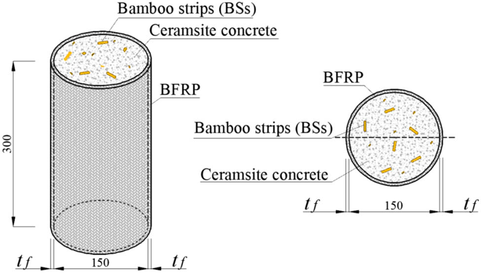
Structural diagram of BFCCC.
Design parameters
| Number | Test series | Height H (mm) | Internal diameter D (mm) | Concrete strength | BFRP layers | Content of BSs (%) | Number of specimens |
|---|---|---|---|---|---|---|---|
| 1 | F0B0 | 300 | 150 | LC30 | 0 | 0 | 3 |
| 2 | F0B0.5 | 300 | 150 | LC30 | 0 | 0.5 | 3 |
| 3 | F0B1.0 | 300 | 150 | LC30 | 0 | 1.0 | 3 |
| 4 | F0B2.0 | 300 | 150 | LC30 | 0 | 2.0 | 3 |
| 5 | F0B4.0 | 300 | 150 | LC30 | 0 | 4.0 | 3 |
| 6 | F0B6.0 | 300 | 150 | LC30 | 0 | 6.0 | 3 |
| 7 | F1B0 | 300 | 150 | LC30 | 1 | 0 | 3 |
| 8 | F1B1.0 | 300 | 150 | LC30 | 1 | 1.0 | 3 |
| 9 | F1B2.0 | 300 | 150 | LC30 | 1 | 2.0 | 3 |
| 10 | F1B4.0 | 300 | 150 | LC30 | 1 | 4.0 | 3 |
| 11 | F2B0 | 300 | 150 | LC30 | 2 | 0 | 3 |
| 12 | F2B1.0 | 300 | 150 | LC30 | 2 | 1.0 | 3 |
| 13 | F2B2.0 | 300 | 150 | LC30 | 2 | 2.0 | 3 |
| 14 | F2B4.0 | 300 | 150 | LC30 | 2 | 4.0 | 3 |
| 15 | F3B0 | 300 | 150 | LC30 | 3 | 0 | 3 |
| 16 | F3B1.0 | 300 | 150 | LC30 | 3 | 1.0 | 3 |
| 17 | F3B2.0 | 300 | 150 | LC30 | 3 | 2.0 | 3 |
| 18 | F3B4.0 | 300 | 150 | LC30 | 3 | 4.0 | 3 |
Note: The specimen’s name consists of two parts, where “F” represents BFRP and “B” represents BSs, followed by the number of BFRP layers and the volume content of BSs.
2.2 Test material
2.2.1 Ceramsite concrete
LC30 shale ceramsite concrete was used, and the proportions are shown in Table 2. The concrete was cured for 28 days, and the average compressive strength of ceramsite concrete (Φ 150 mm × 300 mm) was 33.03 MPa.
Design of concrete proportions
| Cement (kg) | Silica fume (kg) | Fly ash (kg) | River sand (kg) | Ceramsite (kg) | Water (kg) | Water-reducing agent (%) | Thickening agent (g) |
|---|---|---|---|---|---|---|---|
| 425 | 37.5 | 37.5 | 661 | 515 | 150 | 0.40 | 225 |
The material used to prepare ceramsite concrete was Zhonglian cement (P. O 42.5). Grade 700 shale ceramsite was selected, as shown in Figure 2(a), and the specific parameters are shown in Table 3.

Test materials. (a) Grade 700 shale ceramsite, (b) BSs, and (3) BFRP.
Parameters of shale ceramsite
| Ceramsite | Particle size (mm) | Accumulation density (kg·m−3) | Cylinder compressive strength (MPa) | 1 h water absorption (%) |
|---|---|---|---|---|
| Shale ceramsite | 5–20 | 653 | 5.6 | 3 |
2.2.2 BSs
The dimensions of the BSs produced by the Dalin Bamboo Sea in Lu’an, Anhui Province were 50 mm × 8 mm × 3 mm (Figure 2b). Before the concrete was poured, the surface of BSs was brushed with epoxy resin glue to prevent corrosion and increase adhesion with the concrete.
2.2.3 BFRP
BFRP with a nominal thickness of 0.167 mm was used, as shown in Figure 2c. The BFRP tensile testing are shown in Figure 3, and the tensile test results of the BFRP specimens are shown in Table 4. Five material specimens were tested in total, and the average ultimate tensile strength, elastic modulus E f, and ultimate tensile strain ε f were 1641.8 MPa, 74.3 GPa, and 2.22%, respectively.

Tensile test of BFRP. (a) BFRP tensile testing and (b) tensile specimens of BFRP.
Tensile test results for BFRP specimens
| Specimen number | Ultimate load (N) | Ultimate tensile strength (MPa) | Ultimate displacement (mm) | Ultimate tensile strain (%) | Elastic modulus (GPa) |
|---|---|---|---|---|---|
| 1 | 4,405 | 1758.5 | 1.166 | 2.33 | 75.4 |
| 2 | 3,723 | 1486.2 | 1.032 | 2.06 | 72.0 |
| 3 | 4,233 | 1689.8 | 1.063 | 2.13 | 79.5 |
| 4 | 4,407 | 1759.3 | 1.158 | 2.33 | 76.0 |
| 5 | 3,795 | 1515.0 | 1.119 | 2.24 | 67.7 |
| Average | 4,113 | 1641.8 | 1.108 | 2.22 | 74.3 |
2.3 Preparation of specimens
The density of ceramsite aggregate is small and the aggregate is easy to float during pouring and vibration. It is of great significance to control the floating of ceramsite aggregates to improve the quality of concrete. In accordance with JGJT 12-2019 [4], the following methods were mainly adopted to solve the problem of ceramsite aggregates floating:
1) Aggregates with rough and unsmooth surfaces were used to increase the adhesion with cement mortar;
2) Aggregates were pre-wetted in advance, and fly ash and silica fume were reasonably added to the concrete to reduce the density difference between ceramsite aggregates and cement mortar;
3) Thickener agent and water-reducing agent were used to increase the viscosity of the concrete mixture and improve the floating of ceramsite aggregate;
4) The vibration time is controlled to avoid excessive vibration.
Figure 4 shows the specific production process of BFCCCs. The ceramsite was loose and porous with high water absorption. Shale ceramsite was soaked in water for 24 h to achieve self-curing of concrete [54], and removed to drain the surface water 0.5 h before concrete was poured. The length of BFRP was cut according to the different numbers of layers, 0.5 more lap lengths were reserved, and epoxy resin glue was used to paste BFRP sheets.

Preparation of specimens. (a) Pre-wetted ceramsite, (b) pouring of concrete, (c) curing of concrete, (d) gluing of BFRP, (e) polishing, and (f) attaching strain gauges.
2.4 Test setup and loading
A 3,000 kN high-stiffness concrete testing machine was used for loading. The specimens were preloaded three times before formal testing. The loading mode with deformation control was adopted, with a rate of 0.2 mm·min−1, and the test was terminated when the bearing capacity significantly decreased after FRP failure.
Before the test, four axial strain (AS) gauges and four lateral strain (LS) gauges were symmetrically glued on the middle of the specimen, and they were used to measure the strain in the middle. Additionally, two laser displacement sensors (LDSs) and two linear variable differential transformers (LVDTs) were symmetrically arranged in the vertical direction on the specimen to measure the axial deformation of the specimen. The test setup and loading are shown in Figure 5.
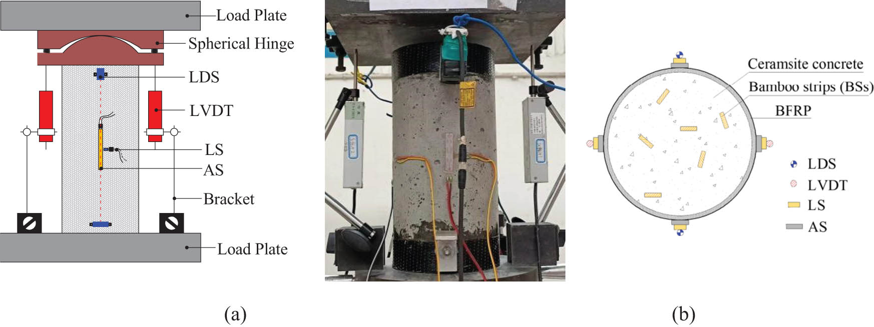
Loading and test setup. (a) Loading and (b) test setup.
3 Test results
3.1 Test phenomenon
3.1.1 Failure modes of unconfined ceramsite concrete
The failure process of ceramsite concrete specimens without BSs is shown in Figure 6a. After cracking, the cracks quickly penetrated, and the concrete between the cracks began to fall off in chunks, causing the specimen to lose its bearing capacity immediately. Finally, that cracks ran through the ceramsite aggregate to form a shear surface (as shown in Figure 6d), which showed obvious brittleness that was quite different from that of normal concrete when cracks bypassed the aggregate particles. This was mainly because the ceramsite aggregate had great brittleness and low strength, and thus the ceramsite was prone to failure [12,55]. The failure modes of unconfined ceramsite concrete columns reinforced with BSs are shown in Figure 6b–c. The number of visible cracks was reduced before the load reached the peak load. The descending section of the load–displacement curve became gentle and exhibited ductile failure. After the failure, the concrete surface was relatively intact without obvious concrete falling off due to the effect of the BSs.
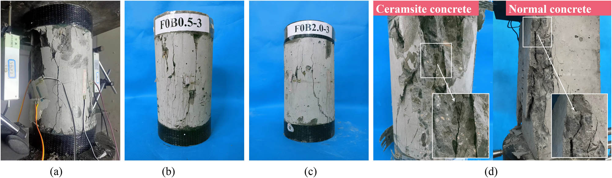
Failure modes of unconfined ceramsite concrete columns. (a) F0B0, (b) F0B0.5, (c) F0B2.0, and (d) shear surface.
3.1.2 Failure modes of BFCCCs
The failure modes of the BFCCCs are shown in Figure 7. There was no obvious phenomenon during the elastic stage of the specimen. When the load was close to the peak load, the lateral confinement effect of BFRP was gradually activated, and there was a continuous slight sound as epoxy glue cracked. Then, the test force quickly reached the peak and rapidly decreased. When the test force was reduced to 80–90% of the peak load, the test force started to rise slowly. When the load reached a certain level, expansion deformation gradually occurred in the middle of the specimen. This was observed as the braid in the local area of the BFRP surface gradually started to turn white, and the area gradually increased in size. During this stage, the specimen could undergo large deformation without damage. When the strain of BFRP reached its fracture strain, it suddenly cracked, and brittle failure occurred with a loud noise. Then, the specimen lost its bearing capacity.
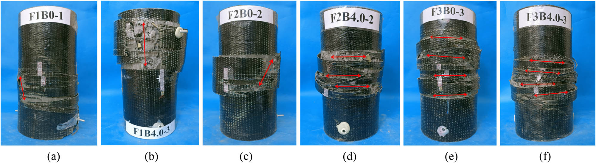
Failure modes of BFCCCs. (a) F1B0-1, (b) F1B4.0-3, (c) F2B0-2, (d) F2B4.0-2, (e) F3B0-3, (f) F3B4.0-3.
There were mainly two types of failure modes of the specimens, most of which were intermediate failures, attributed to significant deformation in the middle of the specimen, and a few were two end failures, possibly due to eccentric compression or internal defects. In addition, when the number of BFRP layers was small, the failure modes mainly showed axial cracking, while when the number of layers was large, the failure modes showed lateral cracking, because the more the number of BFRP layers, the stronger the lateral confinement.
3.2 Stress–strain curves
The stress–strain curves of specimens were obtained based on the test data. The stress was obtained by dividing the test axial compressive load by the initial cross-sectional area of the specimens. The strain at the elastic stage was measured by the strain gauge, and the data of LDSs and LVDTs were used to convert and correct AS at each subsequent stage [6,56].
3.2.1 Stress–strain curves of unconfined ceramsite concrete columns
To more clearly compare the changes in the curves for specimens with different contents of BSs, one specimen was selected from each series. Each curve could be divided into three stages: elastic stage, elastic-plastic stage, and descending stage, as shown in Figure 8. In the elastic stage, the load increased rapidly with the increase in axial deformation, while the LS increased slowly. As the specimen entered the elastic-plastic stage, the stiffness of the specimen decreased, showing nonlinear changes. When the strain reached approximately 0.002, the stress of the specimen reached the peak. With the increase in the load, the specimen entered the descending stage, and the stress decreased rapidly. The compressive strength of ceramsite concrete reinforced with BSs was improved compared with that of concrete without BSs.

Stress–strain curves of unconfined ceramsite concrete columns.
3.2.2 Stress–strain curves of BFCCCs
The stress–strain curves of the BFCCCs could be divided into three stages: elastic stage, transition stage, and strengthening stage, as shown in Figure 9. In the elastic stage, the stress–strain was similar to unconfined concrete, the LS increased slowly, and the confinement of BFRP was not demonstrated. When the axial stress of the specimen approached the peak stress, the curve entered the transition stage. At this time, cracks in the concrete gradually formed, lateral expansion and deformation occurred, concrete played a major role, and the lateral confinement effect of BFRP was gradually activated but was weak. It is worth noting that the stress decreased after reaching the peak point, which was similar to the research conclusion of Liu et al. [6,50,57]. This phenomenon was attributed to the brittleness and low expansibility of ceramsite concrete. Its rapid expansion had an obvious hysteresis effect compared with normal concrete, resulting in delayed activation of the FRP confinement effect [48]. At the peak point, cracks developed rapidly in ceramsite concrete and ran through the ceramsite aggregate particles, resulting in limited lateral deformation and the loss of bearing capacity of the core concrete. At this time, the confinement of BFRP was weak, and the stress decreased rapidly. With a further increase in deformation, the ceramsite concrete became more compact. With the rapid development of lateral deformation, the confinement effect of BFRP gradually increased and could provide stable confinement, the stress was no longer reduced but gradually increased, and the curve entered the strengthening stage. The load increased slowly, and the specimen could undergo large deformation before reaching the ultimate failure point at this stage.

Stress–strain curves of the BFCCCs. (a) B0 series, (b) B1.0 series, (c) B2.0 series, and (d) B4.0 series.
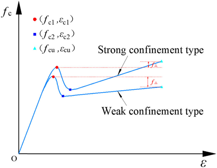
Typical stress–strain curve of BFCCCs is shown in Figure 10b. When the ceramsite concrete was not confined, the stress–strain curve reached the peak point (f co, ε co), and the stress decreased significantly, which could be divided into three stages: elastic stage (Ⅰa), elastic‒plastic stage (Ⅱa), and descending stage (Ⅲa). The stress–strain curves of the BFCCCs showed softening in which the curve rose and fell, which were different from the two-stage equation (parabolic + straight line) proposed by Lam and Teng [58] (Figure 10a). The stress–strain curves were related to the FRP confinement strength, the properties of concrete, etc. [59]. The curve could be divided into three stages: elastic stage (Ⅰb), transition stage (Ⅱb), and strengthening stage (Ⅲb). When the specimen reached the first peak point B (f c1, ε c1), the stress dropped sharply to the lowest point after peak point C (f c2, ε c2), and the softening section (BC) occurred. Next due to the confinement of BFRP being gradually increased, the stress of the specimen was gradually restored, the secondary strengthening stage appeared, and finally, the failed FRP specimen was destroyed. The point that defined the beginning of BFRP failure was the ultimate point D (f cu, ε cu).
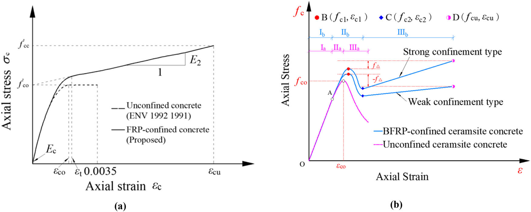
Typical stress–strain curves of FRP-confined concrete. (a) FRP-confined concrete (Lam and Teng) and (b) BFCCC in this study.
The more layers of BFRP that were used, the stronger the lateral confinement. The stress–strain curve showed different branches after the transition section when the number of BFRP layers differed. According to whether the stress at the ultimate point of the specimen exceeded the stress at the peak point, the curves were classified into two different types: weak confinement type (1-layer and 2-layer BFRP) and strong confinement type (3-layer BFRP), as shown in Figure 10b.
To systematically analyze the influence of the BFRP and BSs on the mechanical performance of ceramsite concrete, the test results are summarized in Table 5.
Test results for axial compression
| Test series | P c1 (kN) | f c1 (MPa) | ε c1 | f c2 (MPa) | ε c2 | P cu (kN) | f cu (MPa) | ε cu |
|---|---|---|---|---|---|---|---|---|
| F0B0 | 583.33 | 33.03 | 0.0020 | — | — | — | — | — |
| F0B0.5 | 597.17 | 33.81 | 0.0020 | — | — | — | — | — |
| F0B1.0 | 641.44 | 36.32 | 0.0020 | — | — | — | — | — |
| F0B2.0 | 686.72 | 38.88 | 0.0021 | — | — | — | — | — |
| F0B4.0 | 633.61 | 35.87 | 0.0021 | — | — | — | — | — |
| F0B6.0 | 516.98 | 29.27 | 0.0021 | — | — | — | — | — |
| F1B0 | 690.78 | 39.11 | 0.0020 | 31.12 | 0.0031 | 553.84 | 31.36 | 0.0121 |
| F1B1.0 | 739.59 | 41.87 | 0.0021 | 30.30 | 0.0035 | 557.37 | 31.56 | 0.0123 |
| F1B2.0 | 790.75 | 44.77 | 0.0021 | 33.24 | 0.0035 | 567.62 | 32.14 | 0.0130 |
| F1B4.0 | 743.65 | 42.10 | 0.0021 | 30.64 | 0.0033 | 565.20 | 32.00 | 0.0137 |
| F2B0 | 774.15 | 43.83 | 0.0021 | 32.41 | 0.0039 | 646.51 | 36.60 | 0.0185 |
| F2B1.0 | 811.95 | 45.97 | 0.0022 | 33.14 | 0.0032 | 659.69 | 37.35 | 0.0180 |
| F2B2.0 | 871.64 | 49.35 | 0.0022 | 35.76 | 0.0032 | 688.84 | 39.00 | 0.0194 |
| F2B4.0 | 775.09 | 42.80 | 0.0023 | 31.84 | 0.0034 | 679.42 | 38.47 | 0.0184 |
| F3B0 | 855.10 | 48.41 | 0.0023 | 37.47 | 0.0028 | 808.76 | 45.79 | 0.0234 |
| F3B1.0 | 883.54 | 50.02 | 0.0024 | 40.96 | 0.0032 | 925.75 | 52.41 | 0.0267 |
| F3B2.0 | 922.57 | 52.23 | 0.0024 | 44.79 | 0.0041 | 967.49 | 54.78 | 0.0260 |
| F3B4.0 | 864.58 | 48.95 | 0.0025 | 42.50 | 0.0039 | 917.74 | 51.96 | 0.0286 |
Note: P c1: peak load of the specimen; P cu: ultimate load of the specimen.
3.3 Comparative analysis
3.3.1 Effect of BFRP layers
The number of BFRP layers did not play a confinement role during the elastic stage, as can be seen from the curve. When the curve entered the transition stage, FRP gradually exerted a confinement effect. The bearing capacity and deformation capacity of the specimen were improved obviously with the increase in the number of BFRP layers (Figure 9a–d). This was attributed to that BFRP could provide effective confinement, keeping the ceramsite concrete in a triaxial compression state, and the lateral expansion of the core concrete was restrained.
The effect of the numbers of BFRP layers on the mechanical properties of ceramsite concrete is shown in Figure 11. The stress and strain at the peak point and ultimate point are the averages of the results for three specimens in the same group. The improvement values of stress and strain of specimens were calculated. The BFRP significantly improved the deformation capacity and bearing capacity of ceramsite concrete columns. Taking the series with 2.0% BSs as an example, compared with the unconfined concrete, the peak stress increased by 15.2, 27, and 34.3%, and the peak strain increased by 2.0, 8.6, and 16.5%, as the number of BFRP layers increased from 1 to 3, respectively. The ultimate stress changed by −17.4, 0.3, and 40.8%, and the ultimate strain increased by 534.8, 849.3, and 1172.2%. The results for other parameter series were similar. It is worth noting that the 1-layer FRP had a negative effect on the ultimate stress, which was mainly attributed to the weak confinement of 1-layer FRP and the obvious softening section of the stress–strain curve.
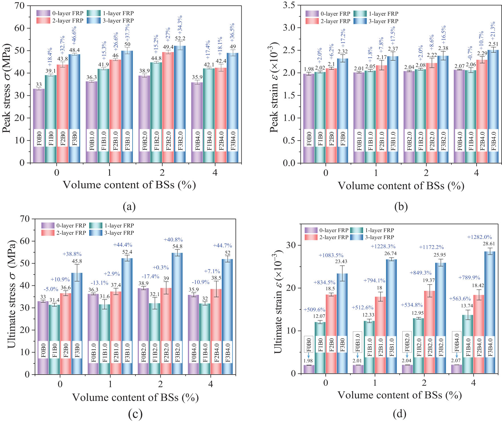
Influence of different numbers of BFRP layers on mechanical performance. (a) Peak stress, (b) peak strain, (c) ultimate stress, and (d) ultimate strain.
3.3.2 Effect of content of BSs
For unconfined concrete, the peak stress increased with the increase in the content of BSs. When the content of BSs was reasonable, the influence on peak strain was not very significant. The decline section of the curve also tended to be gentle due to the effect of BSs, significantly improving the ductility of the specimen (Figure 8). For the stress at the peak point of all specimen curves, the reasonable range of the content of BSs was within 2.0%. The BSs benefitted the compressive bearing capacity and ductility of ceramsite concrete columns within a reasonable volume content range. The improvement in the mechanical properties of BFCCCs with different contents of BSs is shown in Figure 12. It could be seen that the influence on peak stress of BSs was similar to that of unconfined concrete. In addition, BSs had little effect on the ultimate point. During the strengthening stage, due to the compression and compaction of the core concrete, the stress and strain at the ultimate point were mainly affected by BFRP.
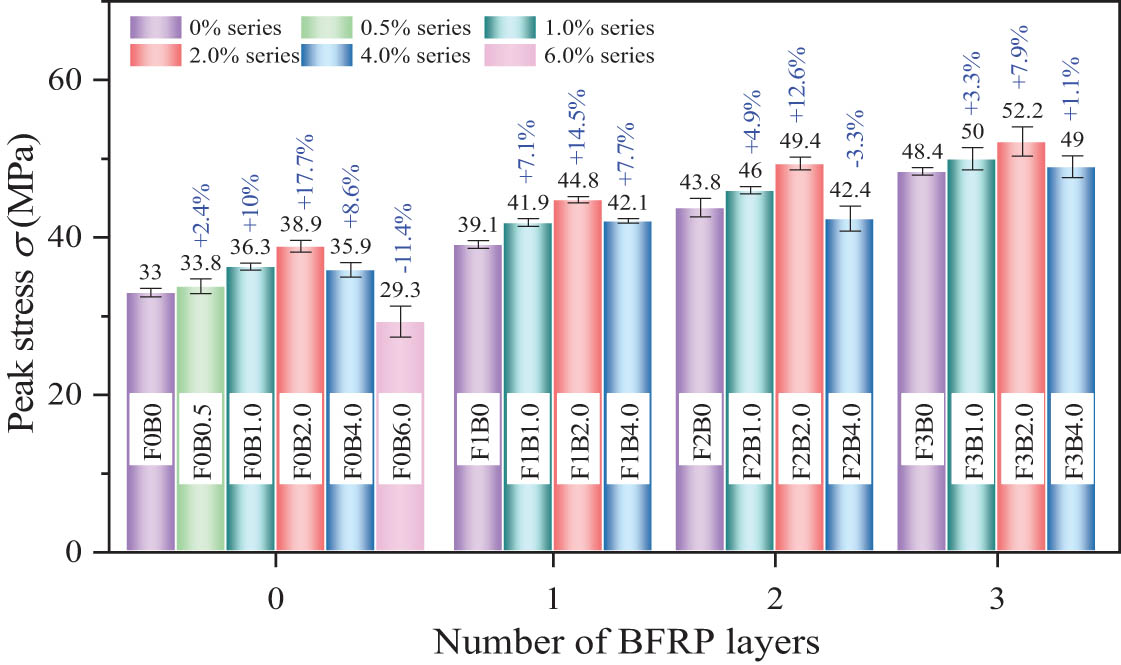
Influence of different contents of BSs on the peak stress.
When the content of BSs was 1.0–2.0%, the peak stress and peak strain increased to different degrees compared to the concrete without BSs. Taking the 2-layer BFRP as an example, the peak stress at the peak point increased by 4.9 and 12.6%, and the peak strain increased by 3.3 and 5.5%. The behavior for other numbers of BFRP layers was similar.
Compared with ceramsite concrete without BSs, the BSs could restrain the generation and expansion of cracks under axial loading and undertook internal tensile stress, and delayed or avoided the occurrence of macroscopic cracks in concrete. Therefore, the BSs could effectively improve the ductility and strength of concrete [60]. When the content of BSs exceeded 2.0%, the main reason for the decrease in strength was that the high content of BSs reduced the workability of the concrete, causing problems in the compaction and production of the specimens. At the same time, BSs were prone to agglomerate, so the optimal content was 2.0%.
4 Stress–strain model
At present, most of the models of FRP-confined concrete are based on normal concrete, and there are few research on models of BFCCC. Ceramsite concrete is different from normal concrete in that it is relatively brittle, and cracks pass through coarse aggregate during failure, showing lower expansibility. Under the same stress, ceramsite concrete undergoes greater axial deformation than normal concrete, and thus the final result deviates largely from that of normal concrete.
4.1 Confinement mechanism
FRP-confined concrete is a passive confinement, and the lateral confinement force of FRP is activated only when the core concrete expands [12]. Due to the brittleness and low expansibility of ceramsite concrete, cracks ran through the ceramsite aggregate when the specimen reached the peak point, which resulted in limited lateral deformation, and the BFRP confinement was weak. After the peak point, the lateral deformation gradually increased with the gradual compaction of the core concrete, and BFRP played an effective role in confinement. The interaction between FRP and concrete is shown in Figure 13.
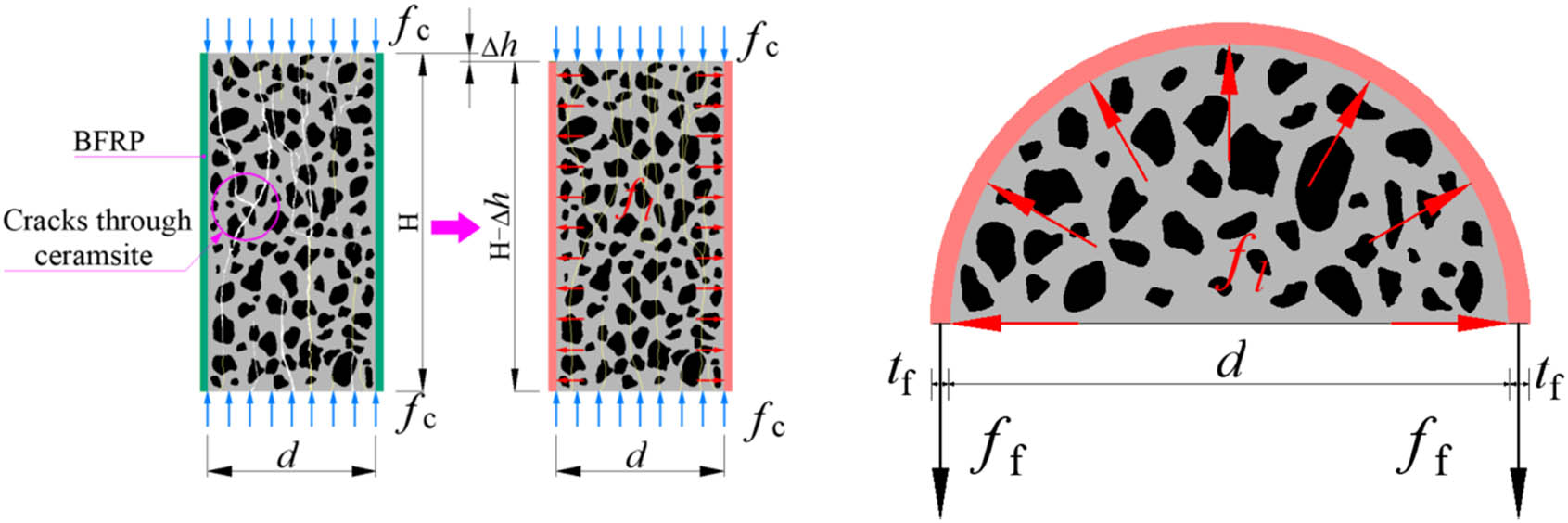
Interaction between FRP and concrete.
The lateral confinement force f l and lateral confinement stiffness E l of FRP determine the lateral deformation capacity of FRP-confined concrete, thus affecting the mechanical performance of the structure. According to the internal force balance, the calculation formula is as follows:
where f f is the ultimate tensile stress of FRP standard specimen, E f is the elastic modulus of FRP, ε f is the ultimate tensile strain of FRP standard specimen, t f is the total thickness of FRP, d is the diameter of core concrete, Δf l is the increment of lateral confinement, and Δε r is the increment of LS.
Pessiki et al. [61] found that the fracture strain of FRP was less than that of the FRP standard tensile specimen and proposed the strain efficiency coefficient k ε , which took into account the degradation of the performance of FRP in lateral tension. According to the experimental results of this article, k ε was taken as 0.665, which was similar to that reported by Guan et al. [48], 0.69. The calculation formula of fracture strain ε h,rup is as follows:
4.2 Existing models
Due to the limited research on BFCCC, the existing classic models of FRP-confined normal concrete were analyzed in this study. Scholars have proposed many strength models, most of which were obtained by adjusting k 1 of f′ cc/f co = 1 + k 1 f l/f co in the strength model proposed by Richard in the early stage, and the ultimate strain was most frequently obtained by adjusting k 2 with the formula ε cu/ε co = 1 + k 2 f l/f co, where f l/f co was used to define the confinement ratio to determine the lateral confinement force of different concrete strengths. However, due to the differences in the quality of the test data and the accuracy of regression by scholars, the k 1 and k 2 values obtained were also quite different. Several representative theoretical models of FRP-confined concrete are collected, as shown in Table 6. See notation for the meaning of each parameter.
Theoretical models of FRP-confined concrete
| No. | Ref. | Peak strength | Ultimate strain |
|---|---|---|---|
| 1 | Lam and Teng [58] (2003) | f′cc/f co = 1 + 3.3f l/f co | ε cu/ε co = 1.75 + 12(f l/f co)(ε h,rup/ε co)0.45 |
| 2 | Wei and Wu [62] (2011) | f′cc/f co = 0.5 + 2.7(f l/f co)0.73 | ε cu/ε co = 1.75 + 12(f l/f co)0.75(f 30/f co)0.62 |
| 3 | Youssef et al. [63] (2007) | f′cc/f co = 1 + 2.25(f l/f co)1.25 | ε cu = 0.003368 + 0.2590(f l /f co)(f f/E f)0.5 |
| 4 | Wu and Wei [64] (2015) | f′cc/f co = 0.75 + 2.7(f l/f co)0.9 | ε cu/ε co = 1.75 + 140(f l/f co)εf 0.6 |
| 5 | Spoelstra and Monti [65] (1999) | f′cc/f co = 0.2 + 3(f l/f co)0.5 | ε cu/ε co = 2 + 1.25(E co/f co)ε f(f l/f co)0.5 |
| 6 | Liu et al. [6] (2020) | f′cc/f co = 1 + 2.06(f l/f co)0.74 | ε cu = 0.0018 + 0.022(f′ cc f l/f co 2)0.76 |
| 7 | Guan et al. [48] (2022) | f′ cc /f co = 1 + 1.95(1.42f l/f co)1.51 | ε cu/ε co = 1.5 + 14[2E f t/(df co/ε co)]0.65(ε h,rup/ε co)0.62 |
| 8 | Zhou et al. [50] (2016) | f′cc/f co = 1 + 2.11(f l/f co)0.65 | ε cu/ε co = 1.5 + 5.24[2Ef t/(df co/ε co)]1.45(ε h,rup/ε co)2.63 |
The maximum value of the peak stress f c1 and ultimate stress f cu in the test was taken as the peak strength f′ cc of the specimen, and the ultimate strain ε cu corresponding to the point (ultimate point) where the FRP starts to fail [58,59]. In this study, f co is the strength of unconfined concrete.
4.3 Evaluation of the existing models
To comprehensively evaluate the accuracy and applicability of the current models and propose a model to predict BFCCCs, three statistical indicators were introduced for quantitative evaluation, namely, the average value (AV), standard deviation (SD), and average absolute error (AAE), as shown in Table 7.
Evaluation of calculation models for characteristic points
| Model | Peak strength | Ultimate strain | ||||
|---|---|---|---|---|---|---|
| AV | SD | AAE (%) | AV | SD | AAE (%) | |
| Lam and Teng [58] | 1.29 | 0.11 | 20.15 | 0.94 | 0.11 | 10.43 |
| Wei and Wu [62] | 1.02 | 0.12 | 11.17 | 0.54 | 0.07 | 45.73 |
| Youssef et al. [63] | 1.02 | 0.05 | 4.05 | 0.59 | 0.07 | 40.94 |
| Wu and Wei [64] | 1.07 | 0.10 | 11.01 | 0.50 | 0.05 | 49.77 |
| Spoelstra and Monti [65] | 1.17 | 0.13 | 17.91 | 1.05 | 0.17 | 15.27 |
| Liu et al. [6] | 1.14 | 0.06 | 37.71 | 0.56 | 0.07 | 44.32 |
| Guan et al. [48] | 1.02 | 0.06 | 5.58 | 0.66 | 0.08 | 34 |
| Zhou et al. [50] | 1.22 | 0.05 | 22.21 | 0.52 | 0.09 | 48.01 |
where Theo. is the theoretical calculated value, Expe. is the test value, and n is the number of specimens.
The next step was to more intuitively analyze the applicability of each model. Figure 14a shows a scatter diagram of the comparison between the calculated peak strength value of each model and the test value, and Figure 14b shows a scatter diagram of the calculated ultimate strain of the model with good fitted results compared with the test value.

Comparison of calculated peak strengths and ultimate strains with test results. (a) Peak strength and (b) ultimate strain.
Analyzing the figure above shows that the peak strength calculated by the above model was generally above the ideal line, and the calculated value was generally larger than the experimental value. The peak strengths calculated by Wei and Wu [62], Youssef et al. [63], Wu and Wei [64], and Guan et al. [48] were relatively similar to the test value, which could approximately predict the peak strength of the BFCCC. However, the above model was mainly based on the “two-stage equation” stress–strain curve, and the two parts of the curve were approximately two straight lines, which differed from the stress–strain curve of BFCCCs.
The ultimate strain calculated by Lam and Teng [58] was relatively accurate. The predicted values of other models were all smaller than the test values, and the predicted values were relatively conservative. This was mainly attributed to the brittleness and low expansion of ceramsite concrete, which tended to produce larger axial deformations when it reached the ultimate point, resulting in larger actual ultimate strains of the specimens [12].
4.4 Proposed stress–strain model
4.4.1 Model of the characteristic point
Liao et al. [66] found three characteristic points in the stress–strain curve when studying FRP-confined ultra-high performance concrete (UHPC) columns, namely, the first peak point, the lowest point after the peak point, and Ultimate failure point. The ratios of the stress and strain of the three characteristic points to the peak stress and strain of unconfined UHPC column f ci/f co and ε ci/ε co are linearly correlated with the actual confinement ratio (f l/f co) a and the lateral fracture strain ratio (ε h,rup/ε co) b , and a general formula for the stress and strain at the characteristic point was proposed,
where ε h,rup is the lateral fracture strain of FRP; f co and ε co are the peak stress and peak strain of unconfined concrete; and k i1, k i2, k i3, k i4, a i , b i , c i , and d i are undetermined parameters. Since ceramsite concrete and UHPC have similar properties of brittleness, low expansion, and post-peak softening behavior of stress–strain curve, and the calculation model for characteristic point of the BFCCC reinforced with BSs could be obtained by improving the characteristic point calculation model of Liao et al.
Figure 15 shows the characteristic points of two types of stress–strain curves (weak confinement and strong confinement) of BFCCCs, where (f c1, ε c1) is the first peak point, (f c2, ε c2) is the lowest point after the peak, and (f cu, ε cu) is the ultimate failure point.
Stress–strain curves of two types of BFCCCs reinforced with BSs.
Based on the test data in this study, regression analysis was conducted on the above formula to obtain the values of the undetermined parameters, as shown in Table 8. The characteristic point calculation model applicable to the BFCCC reinforced with BSs was obtained.
Characteristic point calculation model parameters
| Parameter | First peak point (i = 1) | Lowest point after peak point (i = 2) | Ultimate failure point (i = u) |
|---|---|---|---|
| k i1 | 1 | 0.437 | 0.395 |
| k i2 | 0.115 | 1.224 | 1.496 |
| k i3 | 1 | 1.112 | 1.834 |
| k i4 | 0.418 | 0.120 | 1.810 |
| a i | 0.8 | 0.8 | 0.6 |
| b i | 0.9 | 0.2 | 0.1 |
| c i | 1.0 | 0.1 | 0.1 |
| d i | 0.1 | 0.7 | 0.7 |
The scatter plot in Figure 16 compares the calculated values with the test values. The comparison shows that the calculated values are relatively close to the test values, with errors generally within 15%. The results showed that the proposed model accurately predicted the characteristic points of the BFCCCs reinforced with BSs.

Evaluation of the stress and strain calculation model at the characteristic points. (a) f c1/f co, (b) f c2/f co, (c) f cu/f co, (d) ε c1/ε co, (e) ε c2/ε co, and (f) ε cu/ε co.
4.4.2 Model of the stress–strain curve
To the best of our knowledge, studies of models of the stress–strain curve of BFCCC were rarely reported, and the curve of BFCCC had an obvious softening stage (stress rising-falling-rising), which made it difficult to use a formula to express its complete stress–strain curve. Therefore, the stress–strain curve was divided into two parts and expressed with a subsection function. The first part was the stress rising and falling stage, and the second part was the stress rising stage (secondary strengthening stage).
Based on the model of Popovics [67], Wu and Wei [64] introduced multiple parameters b and c to establish a general model for predicting the stress–strain curve of FRP or steel tube confined concrete columns, which could be used to predict the first part of the curve, as shown in Eq. (9). The expression can model both hardening and softening behavior, and x = ε c /ε c1, where ε c1 is the peak strain.
There are four undetermined parameters in the model: δ is a small constant, with a value of 0.01; for FRP-confined concrete, b = −0.1; and parameters a and c can be calculated by the following formula:
where E c is the elastic modulus of the core concrete, and E sec is the secant modulus at the peak point of the confined concrete, which is calculated by the following formula:
The second part of the curve is approximated by a straight line, and its slope can be calculated through the characteristic points (f c2, ε c2) and (f cu, ε cu). Therefore, the stress–strain model proposed in this study was as follows:
The test curve was calculated and verified according to the model for the stress–strain curve proposed in this study, and the prediction model was applied to fit and compare the test data. As shown in Figure 17, the model curve and the test curve coincided well, and thus the model of Wei et al. accurately simulated the stress–strain trend of BFCCC reinforced with BSs.
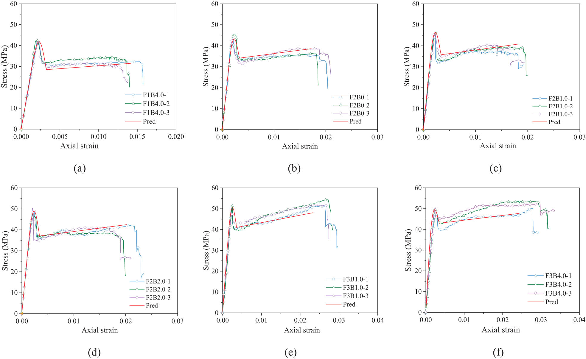
Comparison of models of stress–strain curves of BFCCC reinforced with BSs. (a) F1B4.0 series, (b) F2B0 series, (c) F2B1.0 series, (d) F2B2.0 series, (e) F3B1.0 series, and (f) F3B4.0 series.
5 Conclusion
Based on the test study and theoretical analysis of the axial compression performance of BFCCCs reinforced with BSs, a model for the characteristic point and a model for the stress–strain curve of BFCCC reinforced with BSs were proposed. The main conclusions were as follows:
1) The failure mode of ceramsite concrete occurred when cracks ran through the ceramsite aggregate, which resulted in limited lateral deformation. This differed from normal concrete where cracks bypassed crushed stone aggregate and had obvious brittle characteristics. BFCCCs showed brittle failure when they reached the ultimate failure point.
2) According to the different lateral confinement by BFRP, the stress–strain curves were divided into two different states, namely, strong confinement and weak confinement. In both cases, stress–strain curves had three stages: elastic stage, transition stage, and strengthening stage. Due to the brittleness and low expansion of ceramsite concrete, the stress–strain curve of BFCCC showed that stress decreased and then increased after the peak point, and there was softening behavior. BFRP had a significant impact on the stiffness of the specimen at the strengthening stage.
3) BFRP could significantly improve the bearing capacity and deformation capacity of the specimen. The number of BFRP layers was in the range of 1–3, the bearing capacities of the specimens were improved by 1.17–1.44 times, and the deformation capacities of the specimens were improved by 6.30–12.92 times, compared to unconfined concrete.
4) The optimal volume content of BSs was 2.0%, at which the peak stress was 1.13 times higher, and the peak strain was 1.04 times higher, than for concrete columns without BSs. At less than 2.0% of the optimum content, the stress and strain at peak point increased with increasing content of BSs. When the content of BSs exceeded 2.0%, these improvements were not obvious.
5) Existing models of FRP-confined concrete were evaluated. A stress–strain model suitable for BFCCCs reinforced with BSs was proposed, and the calculation results were in good agreement with the test results. Thus, the proposed model provided better predictions of the stress–strain curves of BFCCCs reinforced with BSs.
Acknowledgments
The authors wish to express their gratitude to the National Natural Science Foundation of China (Nos 52378244 and 51778300), the Natural Science Foundation of Jiangsu Province (No. BK20231293), and Key Research and Development Project of Jiangsu Province (No. BE2020703).
-
Funding information: The National Natural Science Foundation of China (Nos 52378244 and 51778300), the Natural Science Foundation of Jiangsu Province (No. BK20231293), and Key Research and Development Project of Jiangsu Province (No. BE2020703).
-
Author contributions: All authors have accepted responsibility for the entire content of this manuscript and approved its submission.
-
Conflict of interest: The authors state no conflict of interest.
References
[1] Wu, T., X. Yang, H. Wei, and X. Liu. Mechanical properties and microstructure of lightweight aggregate concrete with and without fibers. Construction and Building Materials, Vol. 199, 2019, pp. 526–539.Suche in Google Scholar
[2] Agrawal, Y., T. Gupta, R. Sharma, N. L. Panwar, and S. Siddique. A comprehensive review on the performance of structural lightweight aggregate concrete for sustainable construction. Construction Materials, Vol. 1, No. 1, 2021, pp. 39–62.Suche in Google Scholar
[3] Sohel, K. M. A., K. Al-Jabri, M. H. Zhang, and J. Y. R. Liew. Flexural fatigue behavior of ultra-lightweight cement composite and high strength lightweight aggregate concrete. Construction and Building Materials, Vol. 173, 2018, pp. 90–100.Suche in Google Scholar
[4] JGJT 12-2019. Technical standard for application of lightweight aggregate concrete, China Architecture and Building Press, China, 2019.Suche in Google Scholar
[5] Zhou, Y. W., X. M. Liu, F. Xing, D. G. Li, Y. C. Wang, and L. L. Sui. Behavior and modeling of FRP-concrete-steel double-skin tubular columns made of full lightweight aggregate concrete. Construction and Building Materials, Vol. 139, 2017, pp. 52–63.Suche in Google Scholar
[6] Liu, X., T. Wu, H. Chen, and Y. Liu. Compressive stress-strain behavior of CFRP-confined lightweight aggregate concrete reinforced with hybrid fibers. Composite Structures, Vol. 244, 2020, id. 112288.Suche in Google Scholar
[7] Lu, Y., X. Hu, X. Yang, and Y. Xiao. Comprehensive tests and quasi-brittle fracturemodeling of light-weight foam concrete with expanded clay aggregates. Cement and Concrete Composites, Vol. 115, 2021, id. 103822.Suche in Google Scholar
[8] Sahoo, S., A. K. Selvaraju, and S. S. Prakash. Mechanical characterization of structural lightweight aggregate concrete made with sintered fly ash aggregates and synthetic fibres. Cement and Concrete Composites, Vol. 113, 2020, id. 103712.Suche in Google Scholar
[9] Zhang, M. H. and O. E. Gjvorv. Mechanical properties of high-strength lightweight concrete. Materials Journal, Vol. 88, No. 3, 1991, pp. 240–247.Suche in Google Scholar
[10] Hassanpour, M., P. Shafigh, and H. B. Mahmud. Lightweight aggregate concrete fiber reinforcement - A review. Construction and Building Materials, Vol. 37, 2012, pp. 452–461.Suche in Google Scholar
[11] Wang, P. T., S. P. Shah, and A. E. Naaman. Stress-strain curves of normal and lightweight concrete in compression. Journal Proceedings, Vol. 75, No. 11, 1978, pp. 603–611.Suche in Google Scholar
[12] Lim, J. C. and T. Ozbakkaloglu. Stress-strain model for normal- and light-weight concretes under uniaxial and triaxial compression. Construction and Building Materials, Vol. 71, 2014, pp. 492–509.Suche in Google Scholar
[13] Romualdi, J. P. and G. B. Batson. Mechanics of crack arrest in concrete. Journal of the Engineering Mechanics Division, Vol. 89, No. 3, 1963, pp. 147–168.Suche in Google Scholar
[14] Mirza, F. A. and P. Soroushian. Effects of alkali-resistant glass fiber reinforcement on crack and temperature resistance of lightweight concrete. Cement and Concrete Composites, Vol. 24, No. No. 2, 2002, pp. 223–227.Suche in Google Scholar
[15] Wei, H., T. Wu, X. Liu, and R. Zhang. Investigation of stress-strain relationship for confined lightweight aggregate concrete. Construction and Building Materials, Vol. 256, 2020, id. 119432.Suche in Google Scholar
[16] Choi, J., G. Zi, S. Hino, K. Yamaguchi, and S. Kim. Influence of fiber reinforcement on strength and toughness of all-lightweight concrete. Construction and Building Materials, Vol. 69, 2014, pp. 381–389.Suche in Google Scholar
[17] Chen, B. and J. Y. Liu. Contribution of hybrid fibers on the properties of the high-strength lightweight concrete having good workability. Cement and Concrete Research, Vol. 35, No. 5, 2005, pp. 913–917.Suche in Google Scholar
[18] Liu, X., T. Wu, and Y. Liu. Stress-strain relationship for plain and fibre-reinforced lightweight aggregate concrete. Construction and Building Materials, Vol. 225, 2019, pp. 256–272.Suche in Google Scholar
[19] Wang, H. T. and L. C. Wang. Experimental study on static and dynamic mechanical properties of steel fiber reinforced lightweight aggregate concrete. Construction and Building Materials, Vol. 38, 2013, pp. 1146–1151.Suche in Google Scholar
[20] Libre, N. A., M. Shekarchi, M. Mahoutian, and P. Soroushian. Mechanical properties of hybrid fiber reinforced lightweight aggregate concrete made with natural pumice. Construction and Building Materials, Vol. 25, No. 5, 2011, pp. 2458–2464.Suche in Google Scholar
[21] Kayali, O., M. N. Haque, and B. Zhu. Some characteristics of high strength fiber reinforced lightweight aggregate concrete. Cement and Concrete Composites, Vol. 25, No. 2, 2003, pp. 207–213.Suche in Google Scholar
[22] Xiao, L. G. and G. Z. Li. Basalt fiber for volcanic slag lightweight aggregate concrete research on the impact of performance. IOP Conference Series: Earth and Environmental Science, Vol. 128, No. 1, 2018, id. 012154.Suche in Google Scholar
[23] Yang, T. C., Z. S. Hua, and H. T. Hu. Physical and mechanical properties of the cement composite with Makino bamboo fibers disintegrated by alkali treatment. Wood Material Science & Engineering, Vol. 18, No. 3, 2023, pp. 1076–1085.Suche in Google Scholar
[24] Li, C. F., G. P. Chen, and S. W. Zhu. Study on the properties of straw fiber reinforced cement-based composite. Applied Mechanics and Materials, Vol. 368, 2013, pp. 997–1000.Suche in Google Scholar
[25] Wang, G. H. and Y. Han. Research on the performance of straw fiber concrete. IOP Conference Series: Materials Science and Engineering, Vol. 394, No. 3, 2018, id. 032080.Suche in Google Scholar
[26] Sabarish, K. V., P. Paul, and J. Jones. An experimental investigation on properties of sisal fiber used in the concrete. Materials Today: Proceedings, Vol. 22, 2020, pp. 439–443.Suche in Google Scholar
[27] Du, H., X. M. Hu, Y. F. Meng, and Z. Xie. Study of the shear performance of inclined screws in glulam-concrete composite beams under standard ISO 834 fire. Fire Safety Journal, Vol. 141, 2023, id. 103975.Suche in Google Scholar
[28] Wei, Y., Y. H. Nie, Y. Lin, D. J. Shen, and G. F. Wang. Axial stress strain behaviour of bamboo composite tube confined recycled aggregate concrete with different aggregate replacement ratios. Wood Material Science and Engineering, Vol. 7, 2023, id. 2229275.Suche in Google Scholar
[29] Sharma, B., A. Gatóo, M. Bock, and M. Ramage. Engineered bamboo for structural applications. Construction and Building Materials, Vol. 81, 2015, pp. 66–73.Suche in Google Scholar
[30] Shu, B., Z. Xiao, L. Hong, S. Zhang, C. Li, N. Fu, et al. Review on the application of bamboo-based materials in construction engineering. Journal of Renewable Materials, Vol. 8, No. 10, 2020, pp. 1215–1242.Suche in Google Scholar
[31] Nie, Y. H., Y. Wei, K. T. Miao, K. Zhao, and L. J. Huang. Experimental investigation of full-culm bamboo tubes strengthened by filled concrete and bamboo sheets under axial compression. Journal of Building Engineering, Vol. 45, 2022, id. 103548.Suche in Google Scholar
[32] Dong, C. X., A. K. H. Kwan, and J. C. M. Ho. Axial and lateral stress-strain model for concrete-filled steel tubes with FRP jackets. Engineering Structures, Vol. 126, 2016, pp. 365–378.Suche in Google Scholar
[33] Hamid, K., H. Mostafa, and F. B. Farash. Effect of modified carbon nanotubes epoxy on the mechanical properties of concrete reinforced with FRP sheets. Civil and Environmental Engineering Reports, Vol. 31, No. 3, 2021, pp. 177–196.Suche in Google Scholar
[34] Li, Y. L., J. G. Teng, X. L. Zhao, and R. S. Raman. Theoretical model for seawater and sea-sand concrete-filled circular FRP tubular stub columns under axial compression. Engineering Structures, Vol. 160, 2018, pp. 71–84.Suche in Google Scholar
[35] Wei, Y., J. W. Bai, Y. R. Zhang, K. T. Miao, and K. Q. Zheng. Compressive performance of high-strength seawater and sea sand concrete filled circular FRP-steel composite tube columns. Engineering Structures, Vol. 240, No. 8, 2021, id. 112357.Suche in Google Scholar
[36] Zeng, J. J., W. Y. Gao, Z. J. Duan, Y. L. Bai, Y. C. Guo, and L. J. Ouyang. Axial compressive behavior of polyethylene terephthalate/carbon FRP-confined seawater sea-sand concrete in circular columns. Construction and Building Materials, Vol. 234, 2020, id. 117383.Suche in Google Scholar
[37] Wang, G. F., Y. Wei, K. T. Miao, K. Q. Zheng, and F. H. Dong. Axial compressive behavior of seawater sea-sand coral aggregate concrete-filled circular FRP-steel composite tube columns. Construction and Building Materials, Vol. 315, 2022, id. 125737.Suche in Google Scholar
[38] Wang, G. F., Y. Wei, C. Shen, Z. Huang, and K. Q. Zheng. Compression performance of FRP-steel composite tube-confined ultrahigh-performance concrete (UHPC) columns. Thin-Walled Structures, Vol. 192, 2023, id. 111152.Suche in Google Scholar
[39] Li, P. D., D. Q. Huang, R. Y. Li, R. K. Li, and F. Yuan. Effect of aggregate size on the axial compressive behavior of FRP-confined coral aggregate concrete. Polymers, Vol. 14, No. 18, 2022, id 3877.Suche in Google Scholar
[40] Gao, C., Q. N. Fu, L. Huang, L. B. Yan, and G. M. Gu. Jute fiber-reinforced polymer tube-confined sisal fiber-reinforced recycled aggregate concrete waste. Polymers, Vol. 14, No. 6, 2022, id. 1260.Suche in Google Scholar
[41] Liao, J. J., J. J. Zeng, W. M. Quach, and J. K. Zhou. Axial compressive behavior and model assessment of FRP-confined seawater sea-sand concrete-filled stainless steel tubular stub columns. Composite Structures, Vol. 311, 2023, id. 116782.Suche in Google Scholar
[42] Pimanmas, A. and S. Saleem. Evaluation of existing stress–strain models and modeling of PET FRP–confined concrete. Journal of Materials in Civil Engineering, Vol. 31, No. 12, 2019, id. 04019303.Suche in Google Scholar
[43] Yuan, W. Y., Q. Han, and Y. L. Bai. A unified stress-strain model for LRS FRP-confined concrete columns with square and circular cross-sections. Engineering Structures, Vol. 255, 2022, id. 113900.Suche in Google Scholar
[44] Wei, Y., Y. R. Zhang, J. L. Chai, G. Wu, and Z. Q. Dong. Experimental investigation of rectangular concrete-filled fiber reinforced polymer (FRP)-steel composite tube columns for various corner radii. Composite Structures, Vol. 244, No. 7, 2020, id. 112311.Suche in Google Scholar
[45] Zeng, J. J., J. J. Liao, D. H. Zhu, and P. D. Li. Axial compressive behavior and design-oriented model for large-rupture-strain (LRS) FRP-confined concrete in rectangular columns. Journal of Building Engineering, 2023, id. 106925. 10.1016/j.jobe.2023.106925 Suche in Google Scholar
[46] Wei, Y., C. Zhu, K. T. Miao, J. L. Chai, and K. Q. Zheng. Compressive behavior of rectangular concrete-filled fiber-reinforced polymer and steel composite tube columns with stress-release grooves. Composite Structures, Vol. 281, 2022, id. 114984.Suche in Google Scholar
[47] Guan, H. B., Y. F. Xia, S. C. Zhang, and J. L. Wang. Stress-strain behaviour of spontaneous combustion gangue coarse aggregate concrete under FRP tube confinement. Construction and Building Materials, Vol. 328, 2022, id. 127131.Suche in Google Scholar
[48] Guan, H. B., Y. F. Xia, S. C. Zhang, J. W. Wu, J. L. Wang, and B. Wang. A theoretical axial stress-strain model for gangue ceramsite concrete confined with FRP tube. Construction and Building Materials, Vol. 350, 2022, id. 128864.Suche in Google Scholar
[49] Li, P. D., L. L. Sui, F. Xing, X. X. Huang, Y. W. Zhou, and Y. C. Yun. Effects of aggregate types on the stress-strain behavior of fiber reinforced polymer (FRP)-confined lightweight concrete. Sensors, Vol. 18, No. 10, 2018, id. 3525.Suche in Google Scholar
[50] Zhou, Y. W., X. M. Liu, F. Xing, H. Z. Cui, and L. L. Sui. Axial compressive behavior of FRP-confined lightweight aggregate concrete: An experimental study and stress-strain relation model. Construction and Building Materials, Vol. 119, 2016, pp. 1–15.Suche in Google Scholar
[51] Lam, L. and J. G. Teng. Design-oriented stress-strain model for FRP-confined concrete in rectangular columns. Journal of Reinforced Plastics and Composites, Vol. 22, No. 13, 2003, pp. 1149–1186.Suche in Google Scholar
[52] Teng, J. G., T. Jiang, L. Lam, and Y. Z. Luo. Refinement of a design-oriented stress-strain model for FRP-confined concrete. Journal of Composites for Construction, Vol. 13, No. 4, 2009, pp. 269–278.Suche in Google Scholar
[53] Zhou, Y. W. and Y. F. Wu. General model for constitutive relationships of concrete and its composite structures. Composite Structures, Vol. 94, No. 2, 2012, pp. 580–592.Suche in Google Scholar
[54] Cusson, D. and T. Hoogeveen. Internal curing of high-performance concrete with pre-soaked fine lightweight aggregate for prevention of autogenous shrinkage cracking. Cement and Concrete Research, Vol. 38, No. 6, 2008, pp. 757–765.Suche in Google Scholar
[55] Bogas, J. A. and A. Gomes. Compressive behavior and failure modes of structural lightweight aggregate concrete – Characterization and strength prediction. Materials & Design, Vol. 46, 2013, pp. 832–841.Suche in Google Scholar
[56] Zhang, Y. R., Y. Wei, K. T. Miao, and B. Li. A novel seawater and sea sand concrete-filled FRP-carbon steel composite tube column: Cyclic axial compression behaviour and modelling. Engineering Structures, Vol. 252, 2022, id. 113531.Suche in Google Scholar
[57] Zhang, T., D. Niu, and C. Rong. GFRP-confined coral aggregate concrete cylinders: The experimental and theoretical analysis. Construction and Building Materials, Vol. 218, 2019, pp. 206–213.Suche in Google Scholar
[58] Lam, L. and J. G. Teng. Design-oriented stress-strain model for FRP-confined concrete. Construction and Building Materials, Vol. 17, No. 6–7, 2003, pp. 471–489.Suche in Google Scholar
[59] Yuan, W. Y., Q. Han, Y. L. Bai, X. L. Du, and Q. L. Liu. A unified confinement model of FRP-wrapped concrete cylinder. China Journal of Highway and Transport, Vol. 35, No. 2, 2022, id. 146 (in Chinese).Suche in Google Scholar
[60] Nie, Y. H., Y. Wei, K. Zhao, M. M. Ding, and L. J. Huang. Compressive performance of bamboo sheet twining tube-confined recycled aggregate concrete columns. Construction and Building Materials, Vol. 323, 2022, id. 126544.Suche in Google Scholar
[61] Pessiki, S., K. A. Harries, J. T. Kestner, R. Sause, and J. M. Ricles. Axial behavior of reinforced concrete columns confined with FRP jackets. Journal of Composites for Construction, Vol. 5, No. 4, 2001, pp. 237–245.Suche in Google Scholar
[62] Wei, Y. Y. and Y. F. Wu. Unified stress-strain model of concrete for FRP-confined columns. Construction and Building Materials, Vol. 26, No. 1, 2012, pp. 381–392.Suche in Google Scholar
[63] Youssef, M. N., M. Q. Feng, and A. S. Mosallam. Stress-strain model for concrete confined by FRP composites. Composites Part B: Engineering, Vol. 38, No. 5–6, 2007, pp. 614–628.Suche in Google Scholar
[64] Wu, Y. F. and Y. Wei. General stress-strain model for steel-and FRP-confined concrete. Journal of Composites for Construction, Vol. 19, No. 4, 2015, id. 04014069.Suche in Google Scholar
[65] Spoelstra, M. R. and G. Monti. FRP-confined concrete model. Journal of Composites for Construction, Vol. 3, No. 3, 1999, pp. 143–150.Suche in Google Scholar
[66] Liao, J. J., J. J. Zeng, Q. M. Gong, W. M. Quach, W. Y. Gao, and L. H. Zhang. Design-oriented stress-strain model for FRP-confined ultra-high performance concrete (UHPC). Construction and Building Materials, Vol. 318, 2022, id. 126200.Suche in Google Scholar
[67] Popovics, S. A numerical approach to the complete stress-strain curve of concrete. Cement and Concrete Research, Vol. 3, 1973, pp. 583–599.Suche in Google Scholar
© 2023 the author(s), published by De Gruyter
This work is licensed under the Creative Commons Attribution 4.0 International License.
Artikel in diesem Heft
- Review Articles
- Progress in preparation and ablation resistance of ultra-high-temperature ceramics modified C/C composites for extreme environment
- Solar lighting systems applied in photocatalysis to treat pollutants – A review
- Technological advances in three-dimensional skin tissue engineering
- Hybrid magnesium matrix composites: A review of reinforcement philosophies, mechanical and tribological characteristics
- Application prospect of calcium peroxide nanoparticles in biomedical field
- Research progress on basalt fiber-based functionalized composites
- Evaluation of the properties and applications of FRP bars and anchors: A review
- A critical review on mechanical, durability, and microstructural properties of industrial by-product-based geopolymer composites
- Multifunctional engineered cementitious composites modified with nanomaterials and their applications: An overview
- Role of bioglass derivatives in tissue regeneration and repair: A review
- Research progress on properties of cement-based composites incorporating graphene oxide
- Properties of ultra-high performance concrete and conventional concrete with coal bottom ash as aggregate replacement and nanoadditives: A review
- A scientometric review of the literature on the incorporation of steel fibers in ultra-high-performance concrete with research mapping knowledge
- Weldability of high nitrogen steels: A review
- Application of waste recycle tire steel fibers as a construction material in concrete
- Wear properties of graphene-reinforced aluminium metal matrix composite: A review
- Experimental investigations of electrodeposited Zn–Ni, Zn–Co, and Ni–Cr–Co–based novel coatings on AA7075 substrate to ameliorate the mechanical, abrasion, morphological, and corrosion properties for automotive applications
- Research evolution on self-healing asphalt: A scientometric review for knowledge mapping
- Recent developments in the mechanical properties of hybrid fiber metal laminates in the automotive industry: A review
- A review of microscopic characterization and related properties of fiber-incorporated cement-based materials
- Comparison and review of classical and machine learning-based constitutive models for polymers used in aeronautical thermoplastic composites
- Gold nanoparticle-based strategies against SARS-CoV-2: A review
- Poly-ferric sulphate as superior coagulant: A review on preparation methods and properties
- A review on ceramic waste-based concrete: A step toward sustainable concrete
- Modification of the structure and properties of oxide layers on aluminium alloys: A review
- A review of magnetically driven swimming microrobots: Material selection, structure design, control method, and applications
- Polyimide–nickel nanocomposites fabrication, properties, and applications: A review
- Design and analysis of timber-concrete-based civil structures and its applications: A brief review
- Effect of fiber treatment on physical and mechanical properties of natural fiber-reinforced composites: A review
- Blending and functionalisation modification of 3D printed polylactic acid for fused deposition modeling
- A critical review on functionally graded ceramic materials for cutting tools: Current trends and future prospects
- Heme iron as potential iron fortifier for food application – characterization by material techniques
- An overview of the research trends on fiber-reinforced shotcrete for construction applications
- High-entropy alloys: A review of their performance as promising materials for hydrogen and molten salt storage
- Effect of the axial compression ratio on the seismic behavior of resilient concrete walls with concealed column stirrups
- Research Articles
- Effect of fiber orientation and elevated temperature on the mechanical properties of unidirectional continuous kenaf reinforced PLA composites
- Optimizing the ECAP processing parameters of pure Cu through experimental, finite element, and response surface approaches
- Study on the solidification property and mechanism of soft soil based on the industrial waste residue
- Preparation and photocatalytic degradation of Sulfamethoxazole by g-C3N4 nano composite samples
- Impact of thermal modification on color and chemical changes of African padauk, merbau, mahogany, and iroko wood species
- The evaluation of the mechanical properties of glass, kenaf, and honeycomb fiber-reinforced composite
- Evaluation of a novel steel box-soft body combination for bridge protection against ship collision
- Study on the uniaxial compression constitutive relationship of modified yellow mud from minority dwelling in western Sichuan, China
- Ultrasonic longitudinal torsion-assisted biotic bone drilling: An experimental study
- Green synthesis, characterizations, and antibacterial activity of silver nanoparticles from Themeda quadrivalvis, in conjugation with macrolide antibiotics against respiratory pathogens
- Performance analysis of WEDM during the machining of Inconel 690 miniature gear using RSM and ANN modeling approaches
- Biosynthesis of Ag/bentonite, ZnO/bentonite, and Ag/ZnO/bentonite nanocomposites by aqueous leaf extract of Hagenia abyssinica for antibacterial activities
- Eco-friendly MoS2/waste coconut oil nanofluid for machining of magnesium implants
- Silica and kaolin reinforced aluminum matrix composite for heat storage
- Optimal design of glazed hollow bead thermal insulation mortar containing fly ash and slag based on response surface methodology
- Hemp seed oil nanoemulsion with Sapindus saponins as a potential carrier for iron supplement and vitamin D
- A numerical study on thin film flow and heat transfer enhancement for copper nanoparticles dispersed in ethylene glycol
- Research on complex multimodal vibration characteristics of offshore platform
- Applicability of fractal models for characterising pore structure of hybrid basalt–polypropylene fibre-reinforced concrete
- Influence of sodium silicate to precursor ratio on mechanical properties and durability of the metakaolin/fly ash alkali-activated sustainable mortar using manufactured sand
- An experimental study of bending resistance of multi-size PFRC beams
- Characterization, biocompatibility, and optimization of electrospun SF/PCL composite nanofiber films
- Morphological classification method and data-driven estimation of the joint roughness coefficient by consideration of two-order asperity
- Prediction and simulation of mechanical properties of borophene-reinforced epoxy nanocomposites using molecular dynamics and FEA
- Nanoemulsions of essential oils stabilized with saponins exhibiting antibacterial and antioxidative properties
- Fabrication and performance analysis of sustainable municipal solid waste incineration fly ash alkali-activated acoustic barriers
- Electrostatic-spinning construction of HCNTs@Ti3C2T x MXenes hybrid aerogel microspheres for tunable microwave absorption
- Investigation of the mechanical properties, surface quality, and energy efficiency of a fused filament fabrication for PA6
- Experimental study on mechanical properties of coal gangue base geopolymer recycled aggregate concrete reinforced by steel fiber and nano-Al2O3
- Hybrid bio-fiber/bio-ceramic composite materials: Mechanical performance, thermal stability, and morphological analysis
- Experimental study on recycled steel fiber-reinforced concrete under repeated impact
- Effect of rare earth Nd on the microstructural transformation and mechanical properties of 7xxx series aluminum alloys
- Color match evaluation using instrumental method for three single-shade resin composites before and after in-office bleaching
- Exploring temperature-resilient recycled aggregate concrete with waste rubber: An experimental and multi-objective optimization analysis
- Study on aging mechanism of SBS/SBR compound-modified asphalt based on molecular dynamics
- Evolution of the pore structure of pumice aggregate concrete and the effect on compressive strength
- Effect of alkaline treatment time of fibers and microcrystalline cellulose addition on mechanical properties of unsaturated polyester composites reinforced by cantala fibers
- Optimization of eggshell particles to produce eco-friendly green fillers with bamboo reinforcement in organic friction materials
- An effective approach to improve microstructure and tribological properties of cold sprayed Al alloys
- Luminescence and temperature-sensing properties of Li+, Na+, or K+, Tm3+, and Yb3+ co-doped Bi2WO6 phosphors
- Effect of molybdenum tailings aggregate on mechanical properties of engineered cementitious composites and stirrup-confined ECC stub columns
- Experimental study on the seismic performance of short shear walls comprising cold-formed steel and high-strength reinforced concrete with concealed bracing
- Failure criteria and microstructure evolution mechanism of the alkali–silica reaction of concrete
- Mechanical, fracture-deformation, and tribology behavior of fillers-reinforced sisal fiber composites for lightweight automotive applications
- UV aging behavior evolution characterization of HALS-modified asphalt based on micro-morphological features
- Preparation of VO2/graphene/SiC film by water vapor oxidation
- A semi-empirical model for predicting carbonation depth of RAC under two-dimensional conditions
- Comparison of the physical properties of different polyimide nanocomposite films containing organoclays varying in alkyl chain lengths
- Effects of freeze–thaw cycles on micro and meso-structural characteristics and mechanical properties of porous asphalt mixtures
- Flexural performance of a new type of slightly curved arc HRB400 steel bars reinforced one-way concrete slabs
- Alkali-activated binder based on red mud with class F fly ash and ground granulated blast-furnace slag under ambient temperature
- Facile synthesis of g-C3N4 nanosheets for effective degradation of organic pollutants via ball milling
- DEM study on the loading rate effect of marble under different confining pressures
- Conductive and self-cleaning composite membranes from corn husk nanofiber embedded with inorganic fillers (TiO2, CaO, and eggshell) by sol–gel and casting processes for smart membrane applications
- Laser re-melting of modified multimodal Cr3C2–NiCr coatings by HVOF: Effect on the microstructure and anticorrosion properties
- Damage constitutive model of jointed rock mass considering structural features and load effect
- Thermosetting polymer composites: Manufacturing and properties study
- CSG compressive strength prediction based on LSTM and interpretable machine learning
- Axial compression behavior and stress–strain relationship of slurry-wrapping treatment recycled aggregate concrete-filled steel tube short columns
- Space-time evolution characteristics of loaded gas-bearing coal fractures based on industrial μCT
- Dual-biprism-based single-camera high-speed 3D-digital image correlation for deformation measurement on sandwich structures under low velocity impact
- Effects of cold deformation modes on microstructure uniformity and mechanical properties of large 2219 Al–Cu alloy rings
- Basalt fiber as natural reinforcement to improve the performance of ecological grouting slurry for the conservation of earthen sites
- Interaction of micro-fluid structure in a pressure-driven duct flow with a nearby placed current-carrying wire: A numerical investigation
- A simulation modeling methodology considering random multiple shots for shot peening process
- Optimization and characterization of composite modified asphalt with pyrolytic carbon black and chicken feather fiber
- Synthesis, characterization, and application of the novel nanomagnet adsorbent for the removal of Cr(vi) ions
- Multi-perspective structural integrity-based computational investigations on airframe of Gyrodyne-configured multi-rotor UAV through coupled CFD and FEA approaches for various lightweight sandwich composites and alloys
- Influence of PVA fibers on the durability of cementitious composites under the wet–heat–salt coupling environment
- Compressive behavior of BFRP-confined ceramsite concrete: An experimental study and stress–strain model
- Interval models for uncertainty analysis and degradation prediction of the mechanical properties of rubber
- Preparation of PVDF-HFP/CB/Ni nanocomposite films for piezoelectric energy harvesting
- Frost resistance and life prediction of recycled brick aggregate concrete with waste polypropylene fiber
- Synthetic leathers as a possible source of chemicals and odorous substances in indoor environment
- Mechanical properties of seawater volcanic scoria aggregate concrete-filled circular GFRP and stainless steel tubes under axial compression
- Effect of curved anchor impellers on power consumption and hydrodynamic parameters of yield stress fluids (Bingham–Papanastasiou model) in stirred tanks
- All-dielectric tunable zero-refractive index metamaterials based on phase change materials
- Influence of ultrasonication time on the various properties of alkaline-treated mango seed waste filler reinforced PVA biocomposite
- Research on key casting process of high-grade CNC machine tool bed nodular cast iron
- Latest research progress of SiCp/Al composite for electronic packaging
- Special Issue on 3D and 4D Printing of Advanced Functional Materials - Part I
- Molecular dynamics simulation on electrohydrodynamic atomization: Stable dripping mode by pre-load voltage
- Research progress of metal-based additive manufacturing in medical implants