Axial compression behavior and stress–strain relationship of slurry-wrapping treatment recycled aggregate concrete-filled steel tube short columns
-


Abstract
The utilization of recycled concrete can effectively solve the problems of large accumulations of construction waste and the constant consumption of natural aggregates. Slurry-wrapping modification and concrete-filled steel tubes (CFSTs) are effective approaches to enhance the utilization ratio of recycled concrete. The study involved 4 ordinary CFST columns and 16 slurry-wrapping recycled aggregate concrete-filled steel tube (SRACFST) columns. The variable parameters included the slurry-wrapping recycled aggregate replacement ratio and the section form. The result shows that the ultimate strength of the specimens reached the minimum and maximum at 25 and 100% aggregate replacement ratio. The favorable strength performance of the SRACFST columns is attributed to the dominant positive effect of the slurry-wrapping treatment in reducing matrix porosity over the negative impact of the recycled aggregate’s complex interface transition zone. Due to the hoop factor, the residual bearing ratio peaks at a 25% substitution ratio. Four design standards were used to predict the ultimate strength, with GB50936 and EC4 yielding more accurate estimations, while AISC360-10 and AIJ provided conservative estimations. This study presents the equations of the stress–strain curve for the whole axial compression process, which can be directly applied in the theoretical and numerical analysis of RACFST columns.
1 Introduction
In the global construction industry, population growth has brought forth two significant challenges: the excessive consumption of non-renewable resources and the massive accumulation of construction waste [1]. Extensive stone quarrying has resulted in the depletion of aggregate resources and various ecological problems [2,3,4]. Consequently, an increasing number of nations are considering using recycled concrete to reduce their reliance on ordinary concrete. However, due to the high water absorption, large crushing index, low apparent density, and complex interface transition zone (ITZ) of recycled aggregate, the mechanical properties of recycled concrete are inferior to those of ordinary concrete [5,6]. From the perspective of mortar sticking to the recycled aggregate surface, two main methods for enhancing the physical properties of recycled concrete are considered: strengthening old mortar and removing old mortar [7]. Strengthening old mortar methods that do not introduce components other than recycled concrete has potent effects, such as carbonation treatment, nano-SiO2 treatment, and slurry-wrapping treatment [8,9,10].
The carbonation treatment shows an initial rapid enhancement rate, followed by a slower rate. Pre-soaking in Ca(OH)2 solution prior to treatment significantly increases the carbonation rate, but it results in Ca(OH)2 enrichment, which affects the quality of concrete [11,12]. The nano-SiO2 treatment effectively enhances concrete strength. However, nanomaterials tend to agglomerate, leading to higher construction quality requirements [12]. Wang et al. [13] compared the slurry-wrapping treatment to the carbonation treatment. They concluded that the former not only reduces poor compatibility issues caused by high water absorption but also exhibits superior resistance to chloride ion penetration. Wang et al. [14] conducted an experiment on pre-soaking various recycled aggregates. The results indicated that, regarding the crushing index and strength improvement, the slurry-wrapping treatment with a 0.5 water/cement ratio outperformed the nano-SiO2 treatment. Poon et al. [6] examined the ITZ between the aggregate and the matrix by preparing concrete with three distinct aggregates. This study confirmed that ITZ is a critical factor influencing recycled concrete strength. Martirena et al. [10] demonstrated that slurry-wrapping treatment could enhance the impermeability and porosity of recycled aggregate. Additionally, the treatment facilitated the formation of a thinner and denser ITZ within the concrete. Shi et al. [15] investigated the ITZ of recycled concrete, revealing that pozzolan slurry treatment increased the microhardness and density of the ITZ. The literature demonstrates that the slurry-wrapping treatment has advantages over other modifications, including resistance to chloride ion penetration, improved physical properties of aggregates, and enhanced ITZ. However, these modification methods in the literature have been applied to concrete rather than composite members.
Concrete-filled steel tube (CFST) columns are extensively used in multi-story buildings, bridges, offshore structures, and heavy industrial buildings due to their inherent advantages, including high ductility, strength, and seismic performance [16,17,18]. Tam et al. [19] proposed using recycled concrete to fill the steel tubes in order to incorporate environmental protection measures in CFST column preparation. Xiao et al. [20] performed an axial compression test on recycled aggregate concrete-filled steel tube (RACFST) specimens. The results indicated that the confinement of steel tubes significantly improved the strength and ultimate strain of the core recycled concrete. Ke et al. [21] conducted a high-temperature test of CFST columns. They observed that larger steel tube diameters resulted in more damage to the core concrete. Zhang et al. [22] found that the ultimate bearing capacity and ductility of square RACFST specimens decreased with an increasing replacement ratio. Lyu et al. [23] conducted axial compressive tests on RACFST specimens. The results revealed that the ultimate strength of square and circular RACFST specimens at 100% recycled aggregate replacement decreased by only 6.5 and 7.3%, respectively. Zhou et al. [24] conducted an axial compression test on 32 high titanium slag CFST columns. They found that the hoop coefficient significantly influenced the bearing capacity of short columns, but its effect on medium-long columns was not as pronounced. Bahrami and Nematzadeh [25] and Karimi et al. [26] conducted tests on CFST columns containing rock wool waste and tire rubber. The results showed that while specimens with these waste materials exhibited inferior mechanical properties compared to ordinary CFST, they displayed good high-temperature resistance. Liang et al. [27,28] and Lin et al. [29] performed a series of axial compression tests and proposed the strength calculation models for CFRP-strengthened RACFST columns. The results indicated that specimens with a higher replacement ratio had lower axial stress but larger strain at the peak point [27]. The FRP-confined RACFT column with a higher replacement ratio exhibited a smaller axial strength but tended to exhibit more ductile behavior [28]. The proposed strength calculation models provided more accurate predictions [27,28,29]. de Azevedo et al. [30] suggested that the composite section exhibits a ductile response, and the ductility of ordinary CFST columns is higher than that of RACFST columns. These findings indicate that RACFST columns still possess a certain bearing capacity, despite their limitations relative to ordinary CFST columns. Additionally, their studies mainly focused on the effect of aggregate type, steel tube length, and fiber type on the RACFST column.
Utilization of construction waste is vital to environmental protection, carbon emission reduction, and ore resource conservation. The use of unmodified recycled aggregates in RACFST columns has limitations. It is worthwhile for scholars to study how to improve the utilization ratio of recycled aggregates while ensuring the quality of RACFST columns. Previous studies mainly focused on the effect of aggregate type on RACFST columns, and there were few studies on modified recycled aggregates on RACFST columns. Slurry-wrapping treatment can improve the quality of recycled concrete. Meanwhile, steel tube confinement can improve the performance of recycled concrete. However, few studies have combined the two methods to enhance recycled concrete strength.
Currently, there are limited studies reporting on RACFST columns filled with modified recycled aggregates. This study utilized the slurry-wrapping treatment and steel tubes to enhance the bearing capacity of recycled concrete. Twenty CFST columns were prepared, using the slurry-wrapping aggregate replacement ratio and the steel tube section form as the variation parameters. The axial compressive test revealed the failure mechanism and bearing capacity of the slurry-wrapping RACFST (SRACFST) columns. Moreover, the experiment offers valuable insights for the future application of recycled aggregates in CFST columns.
2 Test overview
2.1 Concrete material properties
Type I Portland cement 42.5 R and Type I fly ash were used for all specimen preparations. A polycarboxylate superplasticizer with a 20% water reduction was produced by Beijing Muhu Admixture Co., which was used to enhance concrete workability. Locally produced manufactured sand with a continuous gradation of 0–5 mm was used as fine aggregates. The recycled aggregate, obtained from disused C30 road pavement, was screened to a particle size of 5–20 mm after secondary crushing. Figure 1 illustrates the particle size distribution curve, tested according to JGJ 52-2006 [31].
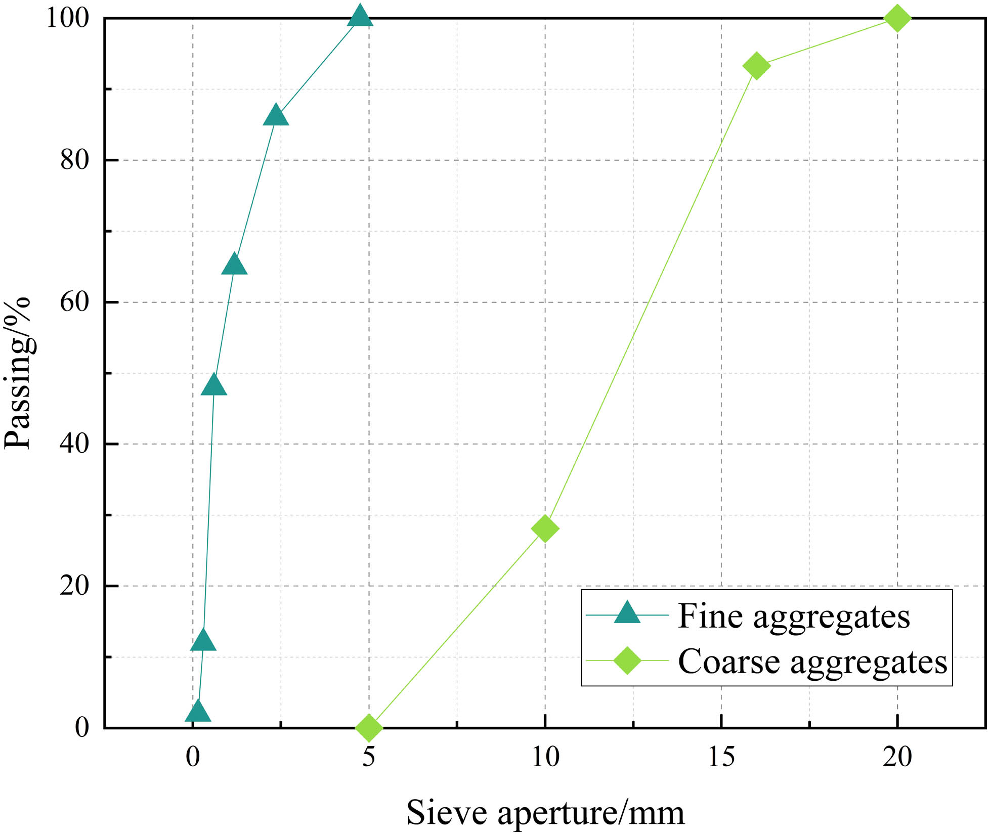
Particle size distribution curve.
2.2 Slurry-wrapping treatment process
To apply the cement slurry for the recycled coarse aggregate, three particle size ranges were used: 5–10, 10–16, and 16–20 mm. The slurry had a water/cement ratio of 0.5 and a fly ash content of 20%. The recycled coarse aggregates were soaked in the slurry, stirred thoroughly for 10 min, poured into a sieve, and rubbed until the slurry stopped dripping. Then, the aggregates were transferred indoors to a shaded area for curing for 3 days before being used in concrete. While transferring the aggregates to the shade, try to separate them. The aggregates of 5–10 mm were found to be difficult to separate. Table 1 and Figure 2 display the basic physical properties and appearance of aggregates.
Basic physical properties of aggregates
| Type | Particle size range (mm) | Water absorption (%) | Moisture content (%) | Crushing index (%) | Apparent density (kg·m−3) | Bulk density (kg·m−3) |
|---|---|---|---|---|---|---|
| Natural aggregate | 5–20 | 0.74 | 0.37 | 8.8 | 2,708 | 1,496 |
| Recycled aggregate | 5–20 | 7.33 | 2.13 | 12.5 | 2,714 | 1,335 |
| Slurry-wrapping recycled aggregate | 5–20 | 5.70 | 2.19 | 12.3 | 2,723 | 1,378 |

Appearance of three types of coarse aggregates: (a) natural aggregate, (b) recycled aggregate, and (c) slurry-wrapping recycled aggregate.
2.3 Steel material properties
The test coupons were made from the same batch of Q235 steel tubes, and testing was conducted following GB/T 228.1-2010 [32]. The stress–strain curve is presented in Figure 3. Table 2 shows Young’s modulus (E s), yield stress (f y), corresponding strain at the yield stress (ε y), ultimate stress (f u), corresponding strain at the ultimate stress (ε u), and Poisson’s ratio (ν).

Tested stress–strain curves of steel.
Physical properties of steel
| Type | E s (GPa) | f y (MPa) | ε y (mm·mm−1) | f u (MPa) | ε u (mm·mm−1) | N (mm·mm−1) |
|---|---|---|---|---|---|---|
| Square steel tube | 203.4 | 262.5 | 0.00598 | 295.4 | 0.14738 | 0.33 |
| Circular steel tube | 202.2 | 272.5 | 0.00754 | 302.4 | 0.13422 | 0.33 |
2.4 Specimen preparation
The 20 specimens were divided into two series: square sections (S series) and circular sections (C series). Five mix proportions were used, which varied with the replacement ratios (the mass percentages of natural aggregate replaced by slurry-wrapping recycled aggregate in concrete). The replacement ratios corresponded to 0 (natural aggregate) and 25, 50, 75, and 100% (slurry-wrapping recycled aggregate). All specimens had a wall thickness of 2 mm and a length of 400 mm. The square specimens had a side length of 100 mm, while the circular tubes had a diameter of 114 mm. Two identical specimens were prepared for each series and replacement ratio to minimize the accidental error. A uniform water/cement ratio of 0.7:0.3:0.41:1.76:1.69 (cement: fly ash: water: sand: coarse aggregate) was used for all concretes. One tube end was welded with a 10 mm thick steel plate, and the concrete was poured in from the open end. After being cured in water for 28 days, the other end was finally welded with a steel plate of the same size. Three 100 × 100 × 100 cubic blocks were prepared simultaneously and tested for compressive strength in accordance with GB/T 50081-2019 [33]. The substitution ratio (r), length (L), width (B) or diameter (D), thickness (t), yield strength (f y), cube compressive strength (f c), prism compressive strength (f ck), hoop coefficient (θ), and ultimate strength (N u) of the specimen are shown in Table 3.
Basic parameters and measured strength of specimens
| Type | R (%) | L (mm) | D(B) (mm) | t (mm) | f y (MPa) | f c (MPa) | f ck (MPa) | θ | N u (kN) |
|---|---|---|---|---|---|---|---|---|---|
| S-0-1/2 | 0 | 400 | 100 | 2 | 262.5 | 48.2 | 36.6 | 0.610 | 579.7 |
| S-25-1/2 | 25 | 400 | 100 | 2 | 262.5 | 33.2 | 25.2 | 0.886 | 442.3 |
| S-50-1/2 | 50 | 400 | 100 | 2 | 262.5 | 43.6 | 33.1 | 0.675 | 531.4 |
| S-75-1/2 | 75 | 400 | 100 | 2 | 262.5 | 47.9 | 36.4 | 0.613 | 569.0 |
| S-100-1/2 | 100 | 400 | 100 | 2 | 262.5 | 48.7 | 37.0 | 0.604 | 607.2 |
| C-0-1/2 | 0 | 400 | 114 | 2 | 272.5 | 48.2 | 36.6 | 0.552 | 722.4 |
| C-25-1/2 | 25 | 400 | 114 | 2 | 272.5 | 33.2 | 25.2 | 0.801 | 577.2 |
| C-50-1/2 | 50 | 400 | 114 | 2 | 272.5 | 43.6 | 33.1 | 0.610 | 675.0 |
| C-75-1/2 | 75 | 400 | 114 | 2 | 272.5 | 47.9 | 36.4 | 0.555 | 717.1 |
| C-100-1/2 | 100 | 400 | 114 | 2 | 272.5 | 48.7 | 37.0 | 0.546 | 736.2 |
Note: θ = (f y × A s)/(f ck × A c); A s = section area of steel tube; A c = section area of concrete.
2.5 Test loading system and measuring point arrangement
The test was conducted using a two-stage graded loading system [34]. In the first stage (0–0.6 P u, predicted ultimate load capacity), the specimen was loaded at a rate of P u/10 per level. In the range of 0.6–0.9 P u, the specimen was loaded at a rate of P u/15 per level. The load was held constant for 2 min at each level. In the second stage, once the load reached 0.9 P u, the loading system switched to displacement control with a 1 mm·min−1 loading rate. The loading was stopped when the specimen was seriously damaged [35].
The test setup is illustrated in Figure 4a. The loading equipment was the SHT-4106 pressure testing machine manufactured by Meters Industrial Systems (China) Co., Ltd. Four YHD-100 displacement gauges were positioned around the specimen. Four sets of strain gauges were symmetrically positioned in the middle of the specimen. Each set of strain gauges included a vertically arranged transverse strain gauge and a longitudinal strain gauge, as shown in Figure 4b.

(a) Test setup and (b) measurement point arrangement.
3 Test results and analysis
3.1 Test phenomena and failure patterns
Figure 5a and b shows the failure pattern of all specimens. During the early loading stage, the surface of all specimens underwent minimal changes. When subjected to the ultimate strength, the middle and upper portions of square specimens and the circumference of circular specimens exhibited slight bulging. At the most unfavorable position where the bulge occurred, the deformation of specimens increased sharply with displacement. At the end of the test, the square specimens exhibited cracks at the weld, and one or two prominent bulging rings appeared in the middle and upper parts. This occurred because the coarse aggregate sank due to gravity when the concrete was being prepared. As a result, the lower part of the specimen became denser, leading to higher bearing capacity and no appearance of bulging rings [22]. Figure 5c illustrates that the square specimens exhibited the typical waist-bulge damage pattern. Figure 5d shows that the circular specimens had one to two obvious bulges along a certain diagonal direction, which represented the typical shear sliding failure. After dismantling all the specimens, it was observed that regardless of the aggregate substitution ratio, the core concrete of square specimens was crushed at the bulge ring, while the circular specimens had an obvious diagonal shear crack at the bulge. Therefore, it can be concluded that the influence of section form on failure pattern is greater than that of the replacement ratio [23,36,37]. The damage pattern of the specimens did not differ significantly with the substitution ratio, consistent with the previous study [38].

Failure patterns of specimens: (a) all the square specimens, (b) all the circular specimens, (c) square specimen destruction mode, (d) circular specimen destruction mode.
3.2 Load–displacement curves
Figure 6 shows the load–displacement curves of the square and circular specimens. The curves of the square specimens are sharper near the peak load, while those of the circular specimens are more rounded. The general trend of the square specimens remains relatively stable regardless of the aggregate substitution ratio. In the initial loading stage, the curves of the square specimens show a specific linear relationship, and they decrease rapidly after reaching the peak load, with the bearing capacity remaining basically unchanged. Different aggregate replacement ratios have an influence on the curve of circular specimens. At the beginning of loading, the curves of circular specimens have a somewhat linear relationship. However, after reaching the peak load, the circular specimen curves drop relatively slowly, and the loads remain stable.

Load–displacement curves of specimens: (a) the square specimens, (b) the circular specimens.
Figure 7 depicts the relationship between the specimens’ ultimate strength N u and ultimate displacement Δ u with different replacement ratios. The ultimate strength tends to first decrease and then increase as the replacement ratio increases, regardless of the section form. Figure 7a shows that under a 25% replacement ratio, the ultimate strength of specimens decreases the most, with the square and circular specimens decreasing by 23.7 and 20.1%, respectively. At a low substitution ratio, the strength decreases due to the weakness of recycled aggregates [39]. However, when the replacement ratio increases to 100%, the ultimate strength increases the most, with the square specimens and circular specimens increasing by 4.7 and 1.9%, respectively. The strength of low- and medium-strength concrete is jointly determined by the ITZ and the porosity of the matrix [40]. Therefore, the strength decrease is attributed to the weakening of the ITZ by the recycled aggregates, resulting in a decrease in concrete strength. In addition, the strength increase is caused by the increase in under-hydrated active material on the aggregate surface [41] and higher water absorption [42], which decreases the actual water/cement ratio and porosity of the matrix. The reduction in matrix porosity has a positive effect that outweighs the negative effect of ITZ weakening, resulting in an increase in concrete strength.

Performance comparison of specimens with replacement ratio: (a) ultimate strength, (b) ultimate displacement.
Figure 7b shows that the ultimate displacement of both square and circular specimens increases with the substitution ratios. Chen et al. [43] attributed the increase in ultimate displacement to the lower stiffness of recycled coarse aggregate compared to natural coarse aggregate. Figure 7b demonstrates a general increase in ultimate displacement with the replacement ratio, which may be attributed to the decrease in recycled concrete’s modulus of elasticity as the aggregate replacement ratio increases [44,45]. At a substitution ratio of 100%, the ultimate displacement of square specimens exhibits the highest increase, reaching 62.4%. Figure 7a and b and Table 3 indicate that, despite the hoop coefficient of square specimens being greater than that of circular specimens, the ultimate strength and ultimate displacement of circular specimens surpass those of square specimens, regardless of the replacement ratio. It suggests that circular specimens are more effective in restraining the core concrete than square specimens, which aligns with the previous study [36].
3.3 Load–strain curve
Figure 8 displays the load–strain curves of both square and circular specimens. During the initial loading stage, both square and circular specimens exhibit linear performance, with the slope of the axial strain greater than the lateral strain. The different Poisson’s ratios between the steel tube and the core concrete result in each being under individual stress during this time, with the steel tube having a minimal impact on the concrete.

Load–strain curves of specimens: (a) the square specimens, (b) the circular specimens.
Following the end of the linear elastic stage, the square and circular specimens exhibit a distinct behavior with increasing load. In the case of most square specimens, the axial and transverse strains maintain a linear relationship until the load reaches 0.9 N u. Subsequently, the transverse strain increases at a faster rate, and the curve’s slope begins to decrease. This occurrence can be attributed to the lateral expansion of the core concrete, resulting in the emergence of a bonding force with the steel tube. When the load reaches 0.75 N u, the axial and transverse strains of circular specimens experience a sudden increase. This sudden increase can be attributed to the decrease in bonding force, indicating that the specimen has entered the yield state.
Upon reaching N u, the curves vary based on the section form of the specimen. In Figure 8a, it can be observed that the load of square specimens decreases sharply with a small strain and then stabilizes, resulting in a prominent point in the load–strain curve. In contrast, the strain increases sharply for circular specimens as shown in Figure 8b, but the load decreases to a lesser extent, resulting in a relatively smoother load–strain curve. This observation suggests that circular specimens have better deformation capacity than square specimens. The difference in deformation capacity is attributed to the more uniform distribution of contact pressure between the tube wall and the core concrete in circular specimens [46]. Rectangular sections experience stress concentrations at the corners, while the constraint near the flat edge is insufficient [47].
Figure 8 shows that the different replacement ratios have a minimal impact on the load–strain curves in the early stage. However, after the specimens have yielded, the curves for different replacement ratios begin to diverge. The influence of the replacement ratios on the ultimate strain is irregular. The replacement ratios have a certain influence on the subsequent load–strain curve, but no significant regular pattern is observed.
3.4 Lateral deformation factor
The lateral deformation factor μ is the ratio of the transverse strain to the longitudinal strain. Figure 9 displays the lateral deformation factor of the specimens. It can be observed that the substitution ratio has a minimal effect on the curves, while the cross-section form significantly influences the results. Circular specimens exhibit more regular curves compared to square specimens. The lateral deformation factor μ of circular specimens remains near 0.3 (Poisson’s ratio of steel [35]) until the load reaches 0.8 N u. In contrast, Poisson’s ratio for concrete is only 0.2 [23], which indicates the effective restraint effect of the circular section.

Lateral deformation factor of the specimens: (a) the square specimens, (b) the circular specimens.
3.5 Analysis of test results
3.5.1 Initial stiffness K 0
The initial stiffness K 0 is a measure of a specimen’s ability to resist elastic deformation under initial stress [48]. The calculation formula is defined as follows:
where N 45% is the strength of the specimens when the applied load reaches 45% of the ultimate strength before damage and Δ 45% is the axial displacement of the specimens when the applied load reaches 45% of the ultimate load before damage.
Figure 10a illustrates that as the replacement ratios increase, the initial stiffness first decreases and then increases. This variation in initial stiffness is attributed to the impact of different replacement ratios on the compressive strength of the core concrete [49].

Analysis of test parameters: (a) initial stiffness, (b) residual bearing ratio, (c) strength improvement factor.
3.5.2 Residual bearing ratio α r
The residual bearing ratio α r is defined as the ratio of the minimum bearing capacity N r to the ultimate strength N u, which is used to measure the continuous bearing capacity of specimens after damage [50]. It is defined as follows:
Figure 10b illustrates that the residual bearing ratio exhibits an upward and then downward trend with the replacement ratio. The maximum residual bearing ratio occurs when the replacement ratio is 25%. This is due to the positive correlation between the residual bearing ratio and the hoop coefficient [51]. Once the hoop factor exceeds a specific value (about 4.5 and 1 for square and circular CFST specimens, respectively), the residual bearing capacity increases even after reaching the ultimate strength [23,52,53]. After reaching the ultimate strength, a higher residual bearing ratio is observed in specimens with lower core concrete strength, indicating a stronger restraint provided by the steel tubes.
3.5.3 Strength improvement factor SI
The strength improvement factor SI, defined by Eqs. (3) and (4), represents the ratio of the ultimate strength N u to the nominal strength N 0. It is used to measure the degree of strength improvement due to the interaction between the steel tube and the concrete.
Figure 10c illustrates that the strength improvement factor of all specimens is greater than 1, irrespective of the replacement ratio. It is attributed to the restraining effect of the steel tube [54], resulting in an ultimate strength of the specimen that is significantly higher than the sum of the steel tube and concrete (N u/(A s f y + A c f c′) > 1). The strength improvement factor is greater for circular specimens than for square specimens. However, the change in strength improvement factor is insignificant for both square and circular specimens with the replacement ratio. It is likely due to the large diameter-to-thickness ratio, which leads to less confining pressure provided by the steel tube and less constraint on the internal core concrete [51].
4 Comparison of test values with national codes
The bearing capacity of CFST short columns with slurry-wrapping recycled aggregates was studied, and the test results were compared with the following codes: Chinese code GB50936 [55], European code EC4 [56], American code AISC360-10 [57], and Japanese code AIJ [58]. The tested compressive strength was transformed due to the different concrete shapes used for calculations in the various codes (prism in China, cylinder in Europe, USA, and Japan) [51]. The cylinder compressive strength (f cc) was obtained by converting the cubic compressive strength (f c) according to the European code (BS EN 1992-1-1-2004) [59]. The prism compressive strength (f ck) was obtained by converting the cubic compressive strength (f c) according to the Chinese code (GB50010-2010) [60]. The conversion results are shown in Table 4.
Conversion table of concrete compressive strength
| Type | NCA/(MPa) | RCA1/(MPa) | RCA2/(MPa) | RCA3/(MPa) | RCA4/(MPa) |
|---|---|---|---|---|---|
| f c | 48.2 | 33.2 | 43.6 | 47.9 | 48.7 |
| f cc | 36.6 | 25.2 | 33.1 | 36.4 | 37.0 |
| f ck | 38.2 | 27.3 | 34.1 | 37.9 | 38.7 |
Note: f c = the cubic compressive strength; f cc = the cylindrical compressive strength; f ck = the prismatic compressive strength.
4.1 Chinese code GB50936
Chinese code GB50936 treats the steel tube and the core concrete as a single entity, studying their combined compressive capacity, which is calculated by multiplying the combined area of CFST (A sc) and the compressive strength of CFST (f sc). The conversion factors for the compressive strength of CFST (f sc) and prism compressive strength (f ck) depend on the section form. The calculation formulas are shown in the following:
where for the square specimens:
4.2 European code EC4
The European code EC4 calculates the CFST bearing capacity using the superposition method, where the total capacity is the sum of the bearing capacity of steel tubes and core concrete. It involves the sum of the products of steel tube area A s and yield strength f y, and concrete area A c and concrete compressive cylinder strength f cc, as shown in Eq. (7). When the section form is circular, and the relative slenderness ratio and eccentricity are small, the coefficients η s and η c can be used to reflect the increase in core concrete strength caused by constraint, as shown in the following equations:
where
4.3 American code AISC360-10
The American code AISC360-10 uses the superposition method to calculate the strength. For the steel tube part, no correction factor is applied, while the concrete part uses correction factors of 0.85 and 0.95 for square and circular specimens, respectively, as shown in Eqs. (11) and (12).
where P e is calculated according to AISC360-10 [57] and the effective length factor is taken as 1.0.
4.4 Japanese code AIJ
The Japanese code AIJ uses the superposition method to calculate the strength. It applies different correction factors to the calculation formulas for different section forms. For square sections, a correction factor of 0.85 is applied to the concrete part; while for circular sections, a correction factor of 1.27 is applied to the steel tube part. The calculation formulas for square and circular specimens are shown in the following equations, respectively:
4.5 Comparative results
The calculation results are presented in Table 5 and Figure 11. It can be observed that the results of the GB50936 and EC4 codes are more accurate, both falling within ±9% of the error range. The EC4 code is the most accurate, with results ranging from −3 to +8%, but the GB50936 calculation is more stable. However, the AISC360-10 and AIJ codes are more conservative, with the maximum exceeding 36 and 20% of the measured values, respectively.
Comparison of measured and calculated bearing capacity
| Type | Calculated values/(kN) | Measured value/(kN) | N u/N CN | N u/N EU | N u/N US | N u/N JP | |||
|---|---|---|---|---|---|---|---|---|---|
| N CN | N EU | N US | N JP | N u | |||||
| S-0 | 620.4 | 557.9 | 499.4 | 505.0 | 579.7 | 0.93 | 1.04 | 1.16 | 1.15 |
| S-25 | 483.8 | 457.4 | 415.6 | 419.7 | 442.3 | 0.91 | 0.97 | 1.06 | 1.05 |
| S-50 | 578.4 | 520.1 | 467.9 | 472.9 | 531.4 | 0.92 | 1.02 | 1.14 | 1.12 |
| S-75 | 617.9 | 555.1 | 497.1 | 502.7 | 569.0 | 0.92 | 1.03 | 1.14 | 1.13 |
| S-100 | 625.3 | 562.5 | 503.2 | 509.0 | 607.2 | 0.97 | 1.08 | 1.21 | 1.19 |
| Mean value | 0.93 | 1.03 | 1.14 | 1.13 | |||||
| Standard deviation | 0.05 | 0.08 | 0.10 | 0.10 | |||||
| Coefficients of variation | 0.05 | 0.08 | 0.09 | 0.09 | |||||
| C-0 | 673.5 | 690.9 | 535.4 | 606.7 | 722.4 | 1.07 | 1.05 | 1.35 | 1.19 |
| C-25 | 533.9 | 591.4 | 437.4 | 503.1 | 577.2 | 1.08 | 0.98 | 1.32 | 1.15 |
| C-50 | 630.5 | 653.4 | 498.5 | 567.7 | 675.0 | 1.07 | 1.03 | 1.35 | 1.19 |
| C-75 | 671.0 | 688.1 | 532.7 | 603.8 | 717.1 | 1.07 | 1.04 | 1.35 | 1.19 |
| C-100 | 678.4 | 695.5 | 539.8 | 611.4 | 736.2 | 1.09 | 1.06 | 1.36 | 1.20 |
| Mean value | 1.08 | 1.03 | 1.35 | 1.18 | |||||
| Standard deviation | 0.02 | 0.06 | 0.03 | 0.04 | |||||
| Coefficients of variation | 0.02 | 0.06 | 0.02 | 0.03 | |||||

Comparison of experimental and calculated values: (a) GB50936, (b) EC4, (c) AISC360-10, (d) AIJ.
5 Axial compressive stress–strain analysis of the specimens
During the axial compression of the specimens, the deformation of the test points was too large and exceeded the permissible range of the strain gauges. The nominal stress–strain curve of the specimens was obtained by transforming the measured axial displacement from the displacement gauges using the appropriate formula and normalizing it [61], as shown in Figure 12. Based on the observed trends, the curves in Figure 12a are divided into ascending, descending, and stable segments, while the curves in Figure 12b are divided into elastic, elastoplastic, descending, and stable segments. Mathematical models for square and circular specimens were established based on the test data from this study and the relevant literature [22,36,61], represented by Eqs. (15) and (16), respectively.
where X = ε/ε u, Y = σ/σ u, ε u = ε scy, σ u = f scy, f scy represents the calculated strength index of specimens, and ε scy represents the strain corresponding to the specimen strength index f scy. For the square specimens, A is the parameter of the ascending section and is recommended to be set to 0.98; B and x A are the parameters of the descending section, and their recommended values are 0.41 and 2.6, respectively; C and D are the stable section parameters, with recommended values of −0.01441 and 0.84289, respectively. For the circular specimen, a and x a are the elastic section parameters and are suggested to take the values of 2 and 0.4, respectively; b is the elastoplastic stage parameter and is recommended to be −0.55; c, d, e, f, x b are the elastic section parameters, with recommended values of 0.1328, −0.6312, 0.81, 0.69, and 2.2, respectively; g is the parameter of the stable segment and is suggested to be set to 0.83.
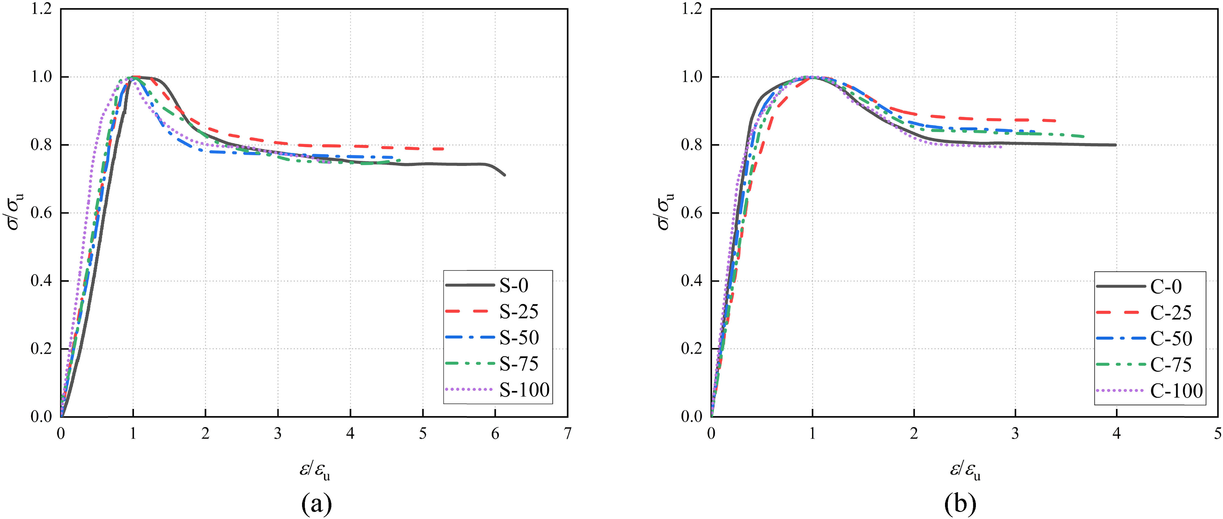
Dimensionless nominal stress–strain curves: (a) the square specimens, (b) the circular specimens.
This study analyzes the fundamental parameters that affect the working mechanism and mechanical properties of specimens. The influence of the slurry-wrapping recycled aggregate replacement ratio and cross-sectional forms on the ultimate stress and ultimate strain is taken into account. The GB50936 code, chosen for its accuracy and stability, is used to establish stress–strain curve expressions for the whole process of the SRACFST specimens. The stress–strain curves for square and circular specimens are given in the following, respectively:
where the correction factors η and φ are the cubic polynomials of the calculated strength index f scy and the calculated strain index ε scy respectively, with respect to the slurry-wrapping recycled aggregate replacement ratio r. The expressions for η and φ are given in the following equations:
for square specimens:
for circular specimens:
Figure 13 compares the calculated stress–strain curve with the test-measured curve for some specimens. The results show a good agreement between the calculated and test-measured curves, indicating the predictability of the whole-process stress–strain curve of the SRACFST using the proposed mathematical expressions.

Comparison of calculated and test-measured stress–strain curves for part specimens: (a) S-0, (b) S-25, (c) S-50, (d) S-75, (e) C-0, (f) C-50, (g) C-75, (h) C-100.
6 Conclusions
This study presents the results of 20 CFST short columns with varying slurry-wrapping recycled aggregate replacement ratios. The study compares the current calculation codes and analyzes the whole-process stress–strain curves of the specimens, leading to the following conclusions:
The ultimate strength decreases and then increases as the replacement ratio increases. The strength of SRACFST columns exhibited a minimum at 25% aggregate replacement and a maximum at 100% aggregate replacement. The positive effect of the slurry-wrapping treatment in enhancing matrix porosity outweighs the negative effect of the complex ITZ of the recycled aggregate, resulting in a favorable strength performance of the SRACFST columns.
Circular CFST columns exhibit higher ultimate strength and displacement compared to the square CFST columns at the same slurry-wrapping recycled aggregate replacement ratio.
The residual bearing ratio of specimens positively correlates with the hoop factor. However, the change in strength improvement factor for circular and square specimens is not significant as the substitution ratios increase.
Among the codes studied, the European Code EC4 demonstrates more prediction of the ultimate load of specimens and the Chinese Code GB50936 exhibits more calculation stability. In contrast, the American Code AISC360-10 and the Japanese Code AIJ tend to calculate more conservatively.
The expression for the whole-process stress–strain curve has been established, and the calculated curve shows good agreement with the test-measured curve.
Slurry-wrapping treatment becomes more complicated for aggregates with particle sizes between 5 and 10 mm. Apply slurry-wrapping treatment to aggregates above 10 mm, which facilitates industrial production.
Acknowledgments
The authors are very grateful to the people involved for their dedication to this work.
-
Funding information: The project was supported by National Natural Science Foundation of China (No. 51968060), which was gratefully acknowledged.
-
Author contributions: All authors have accepted responsibility for the entire content of this manuscript and approved its submission.
-
Conflict of interest: The authors state no conflict of interest.
References
[1] Xu, Z., Z. Huang, C. Liu, X. Deng, D. Hui, and S. Deng. Research progress on mechanical properties of geopolymer recycled aggregate concrete. Reviews on Advanced Materials Science, Vol. 60, No. 1, 2021, pp. 158–172.10.1515/rams-2021-0021Search in Google Scholar
[2] Zhu, P., Y. Hao, H. Liu, X. Wang, and L. Gu. Durability evaluation of recycled aggregate concrete in a complex environment. Journal of Cleaner Production, Vol. 273, 2020, id. 122569.10.1016/j.jclepro.2020.122569Search in Google Scholar
[3] Fareed, S. and A. U. R. Khan. Strengthening of recycled concrete aggregates two-way RC slabs by externally bonded CFRP. International Conference on Fibre-Reinforced Polymer (FRP) Composites in Civil Engineering, 2022.10.1007/978-3-030-88166-5_140Search in Google Scholar
[4] Piccinali, A., A. Diotti, G. Plizzari, and S. Sorlini. Impact of recycled aggregate on the mechanical and environmental properties of concrete: a review. Materials, Vol. 15, No. 5, 2022, id. 1818.10.3390/ma15051818Search in Google Scholar PubMed PubMed Central
[5] Tam, V. W. Y., M. Soomro, and A. C. J. Evangelista. A review of recycled aggregate in concrete applications (2000-2017). Construction and Building Materials, Vol. 172, 2018, pp. 272–292.10.1016/j.conbuildmat.2018.03.240Search in Google Scholar
[6] Poon, C. S., Z. H. Shui, and L. Lam. Effect of microstructure of ITZ on compressive strength of concrete prepared with recycled aggregates. Construction and Building Materials, Vol. 18, No. 6, 2004, pp. 461–468.10.1016/j.conbuildmat.2004.03.005Search in Google Scholar
[7] Shi, C., Y. Li, J. Zhang, W. Li, L. Chong, and Z. Xie. Performance enhancement of recycled concrete aggregate - A review. Journal of Cleaner Production, Vol. 112, 2016, pp. 466–472.10.1016/j.jclepro.2015.08.057Search in Google Scholar
[8] Luo, S., S. Ye, J. Xiao, J. Zheng, and Y. Zhu. Carbonated recycled coarse aggregate and uniaxial compressive stress-strain relation of recycled aggregate concrete. Construction and Building Materials, Vol. 188, 2018, pp. 956–965.10.1016/j.conbuildmat.2018.08.159Search in Google Scholar
[9] Heidari, A. and D. Tavakoli. A study of the mechanical properties of ground ceramic powder concrete incorporating nano-SiO2 particles. Construction and Building Materials, Vol. 38, 2013, pp. 255–264.10.1016/j.conbuildmat.2012.07.110Search in Google Scholar
[10] Martirena, F., T. Castaño, A. Alujas, R. Orozco-Morales, L. Martinez, and S. Linsel. Improving quality of coarse recycled aggregates through cement coating. Journal of Sustainable Cement-Based Materials, Vol. 6, No. 1, 2017, pp. 69–84.10.1080/21650373.2016.1234983Search in Google Scholar
[11] Zhan, B. J., D. X. Xuan, and C. S. Poon. Enhancement of recycled aggregate properties by accelerated CO2 curing coupled with limewater soaking process. Cement & Concrete Composites, Vol. 89, 2018, pp. 230–237.10.1016/j.cemconcomp.2018.03.011Search in Google Scholar
[12] Wang, Y. S., J. L. Zheng, and F. You. Review on enhancement methods of recycled aggregate. Materials Reports, Vol. 35, No. 05, 2021, pp. 5053–5061. in Chinese.Search in Google Scholar
[13] Wang, J., J. Zhang, D. Cao, H. Dang, and B. Ding. Comparison of recycled aggregate treatment methods on the performance for recycled concrete. Construction and Building Materials, Vol. 234, 2020, id. 117366.10.1016/j.conbuildmat.2019.117366Search in Google Scholar
[14] Wang, X. G., M. L. Jiang, X. Chen, Y. G. Wang, J. P. Zhu, and F. Cheng. Effect of different pre-soaked aggregate-PVA fiber on the mechanical properties of recycled aggregate concrete. Acta Materiae Compositae Sinica, Vol. 39, No. 03, 2022, pp. 1205–1214. in Chinese.Search in Google Scholar
[15] Shi, C. J., Z. M. Wu, Z. J. Cao, C. L. Tung, and J. L. Zheng. Performance of mortar prepared with recycled concrete aggregate enhanced by CO2 and pozzolan slurry. Cement & Concrete Composites, Vol. 86, 2018, pp. 130–138.10.1016/j.cemconcomp.2017.10.013Search in Google Scholar
[16] Hasan, H. G., T. Ekmekyapar, and B. A. Shehab. Mechanical performances of stiffened and reinforced concrete-filled steel tubes under axial compression. Marine Structures, Vol. 65, 2019, pp. 417–432.10.1016/j.marstruc.2018.12.008Search in Google Scholar
[17] Hasan, H. G. and T. Ekmekyapar. Bond-slip behaviour of concrete filled double skin steel tubular (CFDST) columns. Marine Structures, Vol. 79, 2021, id. 103061.10.1016/j.marstruc.2021.103061Search in Google Scholar
[18] Ekmekyapar, T. and H. G. Hasan. The influence of the inner steel tube on the compression behaviour of the concrete filled double skin steel tube (CFDST) columns. Marine Structures, Vol. 66, 2019, pp. 197–212.10.1016/j.marstruc.2019.04.006Search in Google Scholar
[19] Tam, V. W. Y., Z. Tao, and A. Evangelista. Performance of recycled aggregate concrete filled steel tubular (RACFST) stub columns with expansive agent. Construction and Building Materials, Vol. 272, 2021, id. 121627.10.1016/j.conbuildmat.2020.121627Search in Google Scholar
[20] Xiao, J. Z., J. Yang, H. J. Huang, and Z. P. Wang. Experimental study on recycled concrete confined by steel tube under axial compression. Journal of Building Structures, Vol. 32, No. 6, 2011, pp. 92–98. in Chinese.Search in Google Scholar
[21] Ke, X., W. Xiang, X. Peng, and Y. Dan. Axial compression performance and residual strength calculation of concrete-encased CFST composite columns exposure to high temperature. Applied Sciences-Basel, Vol. 12, No. 1, 2022, id. 480.10.3390/app12010480Search in Google Scholar
[22] Zhang, X., X. Gao, Y. Ding, P. Xu, G. Zhou, and J. Xu. Axial compression behavior of basalt fiber-reinforced recycled aggregate concrete-filled square steel tubular stub column. Structural Concrete, Vol. 23, No. 1, 2022, pp. 365–381.10.1002/suco.202100016Search in Google Scholar
[23] Lyu, W. Q., L. H. Han, and C. Hou. Axial compressive behaviour and design calculations on recycled aggregate concrete-filled steel tubular (RAC-FST) stub columns. Engineering Structures, Vol. 241, 2021, id. 112452.10.1016/j.engstruct.2021.112452Search in Google Scholar
[24] Zhou, C., W. Chen, X. Ruan, and X. Tang. Experimental study on axial compression behavior and bearing capacity analysis of high titanium slag CFST columns. Applied Sciences-Basel, Vol. 9, No. 10, 2019, id. 2021.10.3390/app9102021Search in Google Scholar
[25] Bahrami, A. and M. Nematzadeh. Bond behavior of lightweight concrete-filled steel tubes containing rock wool waste after exposure to high temperatures. Construction and Building Materials, Vol. 300, 2021, id. 124039.10.1016/j.conbuildmat.2021.124039Search in Google Scholar
[26] Karimi, A., M. Nematzadeh, and S. Mohammad-Ebrahimzadeh-Sepasgozar. Analytical post-heating behavior of concrete-filled steel tubular columns containing tire rubber. Computers & Concrete, Vol. 6, 2020, id. 26.10.1016/j.istruc.2020.07.034Search in Google Scholar
[27] Liang, J., S. Lin, and M. Ahmed. Axial behavior of carbon fiber-reinforced polymer–confined recycled aggregate concrete-filled steel tube slender square columns. Advances in Structural Engineering, Vol. 24, No. 15, 2021, pp. 3507–3518.10.1177/13694332211033964Search in Google Scholar
[28] Liang, J., S. Lin, W. Li, and D. Liu. Axial compressive behavior of recycled aggregate concrete-filled square steel tube stub columns strengthened by CFRP. Structures, Vol. 29, 2021, pp. 1874–1881.10.1016/j.istruc.2020.12.084Search in Google Scholar
[29] Lin, S., Y.-G. Zhao, J. Li, and Z. H. Lu. Confining stress path-based compressive strength model of axially loaded FRP-confined columns. Journal of Composites for Construction, Vol. 25, No. 1, 2021, id. 04020077.10.1061/(ASCE)CC.1943-5614.0001090Search in Google Scholar
[30] de Azevedo, V. S., L. R. O. de Lima, P. C. G. S. Vellasco, M. Tavares, and T. M. Chan. Experimental investigation on recycled aggregate concrete filled steel tubular stub columns under axial compression. Journal of Constructional Steel Research, Vol. 187, 2021, id. 106930.10.1016/j.jcsr.2021.106930Search in Google Scholar
[31] JGJ 52-2006. Standard for technical requirements and test method of sand and crushed stone (or gravel) for ordinary concrete. China Academy of Building Research, 2006.Search in Google Scholar
[32] GB/T 228.1-2010. Metallic materials-tensile testing-part 1: method of test at room temperature. China National Standardization Administration Committee, 2010.Search in Google Scholar
[33] G.T. 50081-2019. Standard for test methods of concrete physical and mechanical properties. China Architecture & Building Press, 2019.Search in Google Scholar
[34] Gao, S., Z. Peng, L. Guo, F. Fu, and Y. Wang. Compressive behavior of circular concrete-filled steel tubular columns under freeze-thaw cycles. Journal of Constructional Steel Research, Vol. 166, 2020, id. 105934.10.1016/j.jcsr.2020.105934Search in Google Scholar
[35] Chen, Z. P., X. J. Ke, J. Y. Xue, and Y. S. Su. Mechanical performance and ultimate bearing capacity calculation of steel tube confined recycled coarse aggregate concrete. China Civil Engineering Journal, Vol. 46, No. 2, 2013, pp. 70–77. in Chinese.Search in Google Scholar
[36] Wang, Y. Y., J. Chen, and Y. Geng. Testing and analysis of axially loaded normal-strength recycled aggregate concrete filled steel tubular stub columns. Engineering Structures, Vol. 86, 2015, pp. 192–212.10.1016/j.engstruct.2015.01.007Search in Google Scholar
[37] Li, P., Y. Zhou, T. Yang, Q. Yang, and F. Xing. Axial compressive behavior of seawater sea-sand recycled aggregate concrete-filled double-skin non-corrosive tubular columns with square cross-section. Thin-Walled Structures, Vol. 167, 2021, id. 108213.10.1016/j.tws.2021.108213Search in Google Scholar
[38] Wang, J. H., C. L. Zheng, B. H. Jin, Y. D. Zhao, S. X. Li, X. Z. Li, et al. Effect of fly ash/different aggregates on the mechanical properties of fibre reinforced self-compacting recycled concrete. Journal of Functional Materials, Vol. 53, No. 9, 2022, pp. 9209–9218. in Chinese.Search in Google Scholar
[39] Mehta, P. K. and P. Monteiro. Concrete: microstructure, properties, and materials, Concrete: microstructure, properties, and materials. 2013.Search in Google Scholar
[40] Chen, Z. P., D. H. Zhan, and J. J. Xu. Research on mechanical properties of recycled concrete using different recycled coarse aggregate replacement. Industrial Construction, Vol. 45, No. 1, 2015, pp. 130–135. in Chinese.Search in Google Scholar
[41] Chen, J., S. Zhang, Y. Wang, and Y. Geng. Axial compressive behavior of recycled concrete filled steel tubular stub columns with the inclusion of crushed brick. Structures, Vol. 26, 2020, pp. 271–283.10.1016/j.istruc.2020.03.045Search in Google Scholar
[42] Wang, Y. Y., J. Chen, B. Zong, and Y. Geng. Mechanical behavior of axially loaded recycled aggregate concrete filled steel tubular stubs and reinforced recycled aggregate concrete stubs. Journal of Building Structures, Vol. 32, No. 12, 2011, pp. 170–177. in Chinese.Search in Google Scholar
[43] Xiao, J. Z. Experimental investigation on complete stress-strain curve of recycled concrete under uniaxial loading. Journal of Tongji University(Natural Science), Vol. 11, 2007, pp. 1445–1449.Search in Google Scholar
[44] Cai, J. M., J. L. Pan, and Q. F. Shan. Failure mechanism of full-size concrete filled steel circle and square tubes under uniaxial compression. Science China-Technological Sciences, Vol. 58, No. 10, 2015, pp. 1638–1647.10.1007/s11431-015-5890-4Search in Google Scholar
[45] Lam, L. and J. G. Teng. Design-oriented stress-strain model for FRP-confined concrete in rectangular columns. Journal of Reinforced Plastics and Composites, Vol. 22, No. 13, 2003, pp. 1149–1186.10.1177/0731684403035429Search in Google Scholar
[46] Yan, J. B., Z. Wang, and J. Xie. Compressive behaviours of double skin composite walls at low temperatures relevant to the arctic environment. Thin-Walled Structures, Vol. 140, 2019, pp. 294–303.10.1016/j.tws.2019.03.047Search in Google Scholar
[47] Yan, J. B., Y. L. Luo, X. C. Lin, Y. B. Luo, N. X. Zhang, and Q. F. Liu. Studies on axial compressive behavior of square concrete filled-high-strength steel tube columns in cold regions, Journal of Tianjin University(Science and Technology). Vol. 55, No. 4, 2022, pp. 402–410. in Chinese.Search in Google Scholar
[48] Wang, Y. B., C. Song, X. Y. Zhao, and G. Li. Experimental study on behavior of circular concrete-filled high-strength steel tubular stub columns under compression. Journal of Building Structures, Vol. 43, No. 11, 2022, pp. 221–234. in Chinese.Search in Google Scholar
[49] Han, L. H. Concrete filled steel tubular structures—theory and practice, 3rd edn, Beijing: China Science Press: 2016.Search in Google Scholar
[50] Shen, M., W. Huang, J. Liu, and Z. Zhou. Axial compressive behavior of rubberized concrete-filled steel tube short columns. Case Studies in Construction Materials, Vol. 16, 2022, id. e00851.10.1016/j.cscm.2021.e00851Search in Google Scholar
[51] Li, P., J. Hu, F. Xing, L. Sui, Y. Zhou, and C. Chen. Behavior and modeling of double-skin tubular columns filled by ultra-lightweight cement composites (ULCCs). Composite Structures, Vol. 263, 2021, id. 113709.10.1016/j.compstruct.2021.113709Search in Google Scholar
[52] GB50936. Technical code for concrete filled steel tubular structures, Ministry of Construction of the People’s Republic of China, 2014.Search in Google Scholar
[53] Eurocode 4. Design of composite steel and concrete structures. part 1-1: general rules and rules for building, European Committee for Standardization, 2004.Search in Google Scholar
[54] AISC360-10. Specification for structural steel buildings, American Institute of Steel Construction, 2010.Search in Google Scholar
[55] AIJ. Recommendations for design and construction of concrete filled steel tubular structures, Architectural Institute of Japan, 2008.Search in Google Scholar
[56] Eurocode 2. Design of concrete structures - general rules and rules for buildings, British Standards Institution, 2004.Search in Google Scholar
[57] GB50010-2010. Code for design of concrete structures, China Academy of Building Research, 2010.Search in Google Scholar
[58] X. G. Zhang, G. Q. Zhou, Y. H. Fan, X. Gao, F. G. Leng, and F. Wang. Axial compressive property of circular steel tubular stub column filled with basalt-fiber reinforced recycled-concrete. Acta Materiae Compositae Sinica, Vol. 40, No. 1, 2023, pp. 369–382 in Chinese.Search in Google Scholar
© 2023 the author(s), published by De Gruyter
This work is licensed under the Creative Commons Attribution 4.0 International License.
Articles in the same Issue
- Review Articles
- Progress in preparation and ablation resistance of ultra-high-temperature ceramics modified C/C composites for extreme environment
- Solar lighting systems applied in photocatalysis to treat pollutants – A review
- Technological advances in three-dimensional skin tissue engineering
- Hybrid magnesium matrix composites: A review of reinforcement philosophies, mechanical and tribological characteristics
- Application prospect of calcium peroxide nanoparticles in biomedical field
- Research progress on basalt fiber-based functionalized composites
- Evaluation of the properties and applications of FRP bars and anchors: A review
- A critical review on mechanical, durability, and microstructural properties of industrial by-product-based geopolymer composites
- Multifunctional engineered cementitious composites modified with nanomaterials and their applications: An overview
- Role of bioglass derivatives in tissue regeneration and repair: A review
- Research progress on properties of cement-based composites incorporating graphene oxide
- Properties of ultra-high performance concrete and conventional concrete with coal bottom ash as aggregate replacement and nanoadditives: A review
- A scientometric review of the literature on the incorporation of steel fibers in ultra-high-performance concrete with research mapping knowledge
- Weldability of high nitrogen steels: A review
- Application of waste recycle tire steel fibers as a construction material in concrete
- Wear properties of graphene-reinforced aluminium metal matrix composite: A review
- Experimental investigations of electrodeposited Zn–Ni, Zn–Co, and Ni–Cr–Co–based novel coatings on AA7075 substrate to ameliorate the mechanical, abrasion, morphological, and corrosion properties for automotive applications
- Research evolution on self-healing asphalt: A scientometric review for knowledge mapping
- Recent developments in the mechanical properties of hybrid fiber metal laminates in the automotive industry: A review
- A review of microscopic characterization and related properties of fiber-incorporated cement-based materials
- Comparison and review of classical and machine learning-based constitutive models for polymers used in aeronautical thermoplastic composites
- Gold nanoparticle-based strategies against SARS-CoV-2: A review
- Poly-ferric sulphate as superior coagulant: A review on preparation methods and properties
- A review on ceramic waste-based concrete: A step toward sustainable concrete
- Modification of the structure and properties of oxide layers on aluminium alloys: A review
- A review of magnetically driven swimming microrobots: Material selection, structure design, control method, and applications
- Polyimide–nickel nanocomposites fabrication, properties, and applications: A review
- Design and analysis of timber-concrete-based civil structures and its applications: A brief review
- Effect of fiber treatment on physical and mechanical properties of natural fiber-reinforced composites: A review
- Blending and functionalisation modification of 3D printed polylactic acid for fused deposition modeling
- A critical review on functionally graded ceramic materials for cutting tools: Current trends and future prospects
- Heme iron as potential iron fortifier for food application – characterization by material techniques
- An overview of the research trends on fiber-reinforced shotcrete for construction applications
- High-entropy alloys: A review of their performance as promising materials for hydrogen and molten salt storage
- Effect of the axial compression ratio on the seismic behavior of resilient concrete walls with concealed column stirrups
- Research Articles
- Effect of fiber orientation and elevated temperature on the mechanical properties of unidirectional continuous kenaf reinforced PLA composites
- Optimizing the ECAP processing parameters of pure Cu through experimental, finite element, and response surface approaches
- Study on the solidification property and mechanism of soft soil based on the industrial waste residue
- Preparation and photocatalytic degradation of Sulfamethoxazole by g-C3N4 nano composite samples
- Impact of thermal modification on color and chemical changes of African padauk, merbau, mahogany, and iroko wood species
- The evaluation of the mechanical properties of glass, kenaf, and honeycomb fiber-reinforced composite
- Evaluation of a novel steel box-soft body combination for bridge protection against ship collision
- Study on the uniaxial compression constitutive relationship of modified yellow mud from minority dwelling in western Sichuan, China
- Ultrasonic longitudinal torsion-assisted biotic bone drilling: An experimental study
- Green synthesis, characterizations, and antibacterial activity of silver nanoparticles from Themeda quadrivalvis, in conjugation with macrolide antibiotics against respiratory pathogens
- Performance analysis of WEDM during the machining of Inconel 690 miniature gear using RSM and ANN modeling approaches
- Biosynthesis of Ag/bentonite, ZnO/bentonite, and Ag/ZnO/bentonite nanocomposites by aqueous leaf extract of Hagenia abyssinica for antibacterial activities
- Eco-friendly MoS2/waste coconut oil nanofluid for machining of magnesium implants
- Silica and kaolin reinforced aluminum matrix composite for heat storage
- Optimal design of glazed hollow bead thermal insulation mortar containing fly ash and slag based on response surface methodology
- Hemp seed oil nanoemulsion with Sapindus saponins as a potential carrier for iron supplement and vitamin D
- A numerical study on thin film flow and heat transfer enhancement for copper nanoparticles dispersed in ethylene glycol
- Research on complex multimodal vibration characteristics of offshore platform
- Applicability of fractal models for characterising pore structure of hybrid basalt–polypropylene fibre-reinforced concrete
- Influence of sodium silicate to precursor ratio on mechanical properties and durability of the metakaolin/fly ash alkali-activated sustainable mortar using manufactured sand
- An experimental study of bending resistance of multi-size PFRC beams
- Characterization, biocompatibility, and optimization of electrospun SF/PCL composite nanofiber films
- Morphological classification method and data-driven estimation of the joint roughness coefficient by consideration of two-order asperity
- Prediction and simulation of mechanical properties of borophene-reinforced epoxy nanocomposites using molecular dynamics and FEA
- Nanoemulsions of essential oils stabilized with saponins exhibiting antibacterial and antioxidative properties
- Fabrication and performance analysis of sustainable municipal solid waste incineration fly ash alkali-activated acoustic barriers
- Electrostatic-spinning construction of HCNTs@Ti3C2T x MXenes hybrid aerogel microspheres for tunable microwave absorption
- Investigation of the mechanical properties, surface quality, and energy efficiency of a fused filament fabrication for PA6
- Experimental study on mechanical properties of coal gangue base geopolymer recycled aggregate concrete reinforced by steel fiber and nano-Al2O3
- Hybrid bio-fiber/bio-ceramic composite materials: Mechanical performance, thermal stability, and morphological analysis
- Experimental study on recycled steel fiber-reinforced concrete under repeated impact
- Effect of rare earth Nd on the microstructural transformation and mechanical properties of 7xxx series aluminum alloys
- Color match evaluation using instrumental method for three single-shade resin composites before and after in-office bleaching
- Exploring temperature-resilient recycled aggregate concrete with waste rubber: An experimental and multi-objective optimization analysis
- Study on aging mechanism of SBS/SBR compound-modified asphalt based on molecular dynamics
- Evolution of the pore structure of pumice aggregate concrete and the effect on compressive strength
- Effect of alkaline treatment time of fibers and microcrystalline cellulose addition on mechanical properties of unsaturated polyester composites reinforced by cantala fibers
- Optimization of eggshell particles to produce eco-friendly green fillers with bamboo reinforcement in organic friction materials
- An effective approach to improve microstructure and tribological properties of cold sprayed Al alloys
- Luminescence and temperature-sensing properties of Li+, Na+, or K+, Tm3+, and Yb3+ co-doped Bi2WO6 phosphors
- Effect of molybdenum tailings aggregate on mechanical properties of engineered cementitious composites and stirrup-confined ECC stub columns
- Experimental study on the seismic performance of short shear walls comprising cold-formed steel and high-strength reinforced concrete with concealed bracing
- Failure criteria and microstructure evolution mechanism of the alkali–silica reaction of concrete
- Mechanical, fracture-deformation, and tribology behavior of fillers-reinforced sisal fiber composites for lightweight automotive applications
- UV aging behavior evolution characterization of HALS-modified asphalt based on micro-morphological features
- Preparation of VO2/graphene/SiC film by water vapor oxidation
- A semi-empirical model for predicting carbonation depth of RAC under two-dimensional conditions
- Comparison of the physical properties of different polyimide nanocomposite films containing organoclays varying in alkyl chain lengths
- Effects of freeze–thaw cycles on micro and meso-structural characteristics and mechanical properties of porous asphalt mixtures
- Flexural performance of a new type of slightly curved arc HRB400 steel bars reinforced one-way concrete slabs
- Alkali-activated binder based on red mud with class F fly ash and ground granulated blast-furnace slag under ambient temperature
- Facile synthesis of g-C3N4 nanosheets for effective degradation of organic pollutants via ball milling
- DEM study on the loading rate effect of marble under different confining pressures
- Conductive and self-cleaning composite membranes from corn husk nanofiber embedded with inorganic fillers (TiO2, CaO, and eggshell) by sol–gel and casting processes for smart membrane applications
- Laser re-melting of modified multimodal Cr3C2–NiCr coatings by HVOF: Effect on the microstructure and anticorrosion properties
- Damage constitutive model of jointed rock mass considering structural features and load effect
- Thermosetting polymer composites: Manufacturing and properties study
- CSG compressive strength prediction based on LSTM and interpretable machine learning
- Axial compression behavior and stress–strain relationship of slurry-wrapping treatment recycled aggregate concrete-filled steel tube short columns
- Space-time evolution characteristics of loaded gas-bearing coal fractures based on industrial μCT
- Dual-biprism-based single-camera high-speed 3D-digital image correlation for deformation measurement on sandwich structures under low velocity impact
- Effects of cold deformation modes on microstructure uniformity and mechanical properties of large 2219 Al–Cu alloy rings
- Basalt fiber as natural reinforcement to improve the performance of ecological grouting slurry for the conservation of earthen sites
- Interaction of micro-fluid structure in a pressure-driven duct flow with a nearby placed current-carrying wire: A numerical investigation
- A simulation modeling methodology considering random multiple shots for shot peening process
- Optimization and characterization of composite modified asphalt with pyrolytic carbon black and chicken feather fiber
- Synthesis, characterization, and application of the novel nanomagnet adsorbent for the removal of Cr(vi) ions
- Multi-perspective structural integrity-based computational investigations on airframe of Gyrodyne-configured multi-rotor UAV through coupled CFD and FEA approaches for various lightweight sandwich composites and alloys
- Influence of PVA fibers on the durability of cementitious composites under the wet–heat–salt coupling environment
- Compressive behavior of BFRP-confined ceramsite concrete: An experimental study and stress–strain model
- Interval models for uncertainty analysis and degradation prediction of the mechanical properties of rubber
- Preparation of PVDF-HFP/CB/Ni nanocomposite films for piezoelectric energy harvesting
- Frost resistance and life prediction of recycled brick aggregate concrete with waste polypropylene fiber
- Synthetic leathers as a possible source of chemicals and odorous substances in indoor environment
- Mechanical properties of seawater volcanic scoria aggregate concrete-filled circular GFRP and stainless steel tubes under axial compression
- Effect of curved anchor impellers on power consumption and hydrodynamic parameters of yield stress fluids (Bingham–Papanastasiou model) in stirred tanks
- All-dielectric tunable zero-refractive index metamaterials based on phase change materials
- Influence of ultrasonication time on the various properties of alkaline-treated mango seed waste filler reinforced PVA biocomposite
- Research on key casting process of high-grade CNC machine tool bed nodular cast iron
- Latest research progress of SiCp/Al composite for electronic packaging
- Special Issue on 3D and 4D Printing of Advanced Functional Materials - Part I
- Molecular dynamics simulation on electrohydrodynamic atomization: Stable dripping mode by pre-load voltage
- Research progress of metal-based additive manufacturing in medical implants