Damage constitutive model of jointed rock mass considering structural features and load effect
-
Bing Sun
 ,
Peng Yang
,
Peng Yang

Abstract
Rock masses in underground engineering are usually damaged, which are caused by rock genesis and environmental stress. Studying the constitutive relationship between rock strength and deformation under loading is crucial for the design and evaluation of such scenarios. The new damage constitutive model considering the dynamic change of joint damage was developed to describe the behavior of rocks under loading in this work. First, considering the influence of jointed rock mass structural features in their entirety, the Drucker–Prager criterion and the Hoek–Brown criterion were combined. Second, based on the idea of macro–micro coupling, the calculation formulae of damage variables were derived. Finally, the damage constitutive model of the jointed rock mass was established, and the proposed model was fitted and compared with the test data. Results show that the variation rules for damage value and peak strength are opposite, and the stress–strain is highly sensitive to changes in the parameter s of the model. Moreover, the proposed model can accurately describe the effect of joint deterioration on the entire process of rock mass compression failure, which shows that the damage constitutive models are useful for evaluating the strength characteristics of jointed rock mass in engineering practice.
1 Introduction
Long-term geological evolution has led to the widespread development of random joint surfaces in rocks. The existence of various scale defects in jointed rock mass from micro to macro makes the mechanical behavior and failure characteristics of rock materials extremely complicated, which has great influence on the safety and long-term stability of rock engineering. Frequently, water conservancy, slopes, and mining engineering are affected by environmental stress – for instance, after the foundation of a hydropower dam is excavated, the stress relaxation of the rock mass of the dam foundation, or even the failure of the dam owing to seepage. Natural and constructed slopes are subject to landslides and cave-ins due to the influences of gravity and vibration. The surrounding rock mass fractures and deforms as a result of the redistribution of stress caused by the excavation of the mining route. Since the constitutive relationship of rock masses is the basis for rational design and assessing the stability of engineering constructions. Consequently, using the damage constitutive relationship to describe the deformation and failure characteristics of the jointed rock mass under stress is one of the hottest research topics. Taking into account the macroscopic with a mesoscopic damage coupling mechanism, the staged deformation characteristics of the jointed rock mass are essential to solve this issue.
The emergence and development of damage mechanics gives a new research concept for examining the mechanical properties and failure mechanism of rocks [1]. Kyoya et al. [2] applied damage theory for the first time to the analysis of initial joint damage of rock mass and established its constitutive relationship. Rocks with different initial damage states can be considered as materials of different properties; based on damage continuum and statistical theory, the constitutive model affected by the loading capacity of the damaged elements is derived [3]. Chen et al. [4,5] created the concepts of damage rate and damage index and discovered that the Weibull distribution can more accurately reflect the transition of rock from brittleness to ductility than power function. Therefore, the micro-unit strength is generally assumed to follow the Weibull distribution [6]. In order to consider joint geometry, strength, and deformation parameters simultaneously, the macro- and mesoscopic damage coupling viewpoint is put forward, and the damage constitutive model of intermittently jointed rock mass is developed [7,8]. In the analysis of the damage evolution law, it is shown that joint inclination has a major effect on initial damage [9,10,11]. Considering the interaction between joints and surrounding rock, a damage-plasticity cohesive-frictional model is established, which enables the model to capture the key characteristics of jointed rock mass responses at different spatial scales [12]. With the advancement of strength theory, the micro-element strength of rock mass is primarily described by the strength criterion connected to the factor of the rock mass strength – the Hoek–Brown (H-B) criteria, which can consider the various factors of the rock quality and the rock strength associated with the surrounding rock [13,14]; the Griffith criterion, which can characterize the fracture failure of brittle materials from an energy perspective [15]; and the Drucker–Prager (D-P) criterion, which can consider the effect of intermediate primary stress and hydrostatic pressure [16,17]. However, the D-P criterion normally produces larger damage zone in numerical simulations as it is a distribution parameter of mesoscopic element strength, so the Mohr–Coulomb (M-C) criterion is used as the distribution parameter of damage-softening statistical constitutive model [18]. Due to the presence of a fissure compaction mechanism in the initial process of rock failure, Wen et al. [19] derived a calculation formula considering the crack closure effect and proposed a statistical damage model of structural surfaces based on the M-C criterion to define the micropore strength of rock structural surfaces [20]. With the deep development of engineering environment, its stress environment is gradually complicated. Since M-C criterion is only suitable for predicting the stress characteristic values of rock at low confining pressure level, after the basic concept of critical confining pressure was introduced, and a nonlinear strength criterion of rock that can consider the transformation of brittle–ductile characteristics was proposed [21]. Based on the relationship between the rock deformation and the deformation of the initial void and the skeleton, a rock deformation analysis model was established [22] and the idea of void strain ratio was introduced [23]. The internal cracks of a rock grow constantly under load, and its strength also fluctuates continuously [24]; in this context, the constitutive model of fissured rock mass was constructed based on the deformation characteristics of compressive micro-cracks under compression [25]. Considering that crack closure and development are accompanied by energy dissipation, Liu et al. [26] and Ma et al. [27] proposed the damage variable based on energy dissipation, respectively. The lateral strain of rock exhibits nonlinear properties throughout the damage and failure processes. Under the circumstance that rock exhibits dilatancy in the compression process, a damage evolution equation considering dilatancy characteristics and post-peak shape was derived [28]. The residual strength after the peak of stress–strain curve plays an important role in the stability of geotechnical system. With the increase of the confining pressure, the residual strength gradually becomes the main factor affecting the posterior section of the rock full stress–strain curve [29]. A theoretical approach to simulate the brittle rock stress–strain curve was proposed by considering the residual strength response of rock materials [30].
Strength criteria are frequently used to determine the micro-element strength of rock masses in previous studies, while the definition of macroscopic damage variables is mostly based on changes in elastic modulus. Some existing constitutive models simulate the stress and deformation of rock mass in stages for a better estimate, but their complexity and number of parameters limit their practicality. Although these studies have made significant advances in the theory of joint fracture damage, they have not considered the effect of joint deterioration on the rock mass failure process under pressure. Moreover, the presence of joint surfaces in actual rock mass engineering will cause varying degrees of deterioration of the rock mass under random stress and will become the primary inducing factor of rock mass failure under certain conditions. To address shortcomings in existing research and characterize jointed damage accurately during loading, the H-B criterion and the D-P criterion are combined to account for the structural features of the rock mass. On the micro-level, the rock mass strength obtained by Griffith criterion is used to establish the micro-damage variable through the idea of element subdivision. Then, a damage constitutive model of jointed rock mass under the coupling action of structural features and load effect is proposed, and the rationality of the model is verified.
2 Damage constitutive model of jointed rock mass considering load and structural features
The natural rock mass contains various scale defects from macro to micro. Various damage defects of different scales will have different effects on the physical and mechanical properties of rock mass. Due to the large number and incomplete penetration of rock mass structural plane, it cannot be considered individually. For engineering rock mass, the distributed joint cracks are regarded as macroscopic defects. If the initial damage state of intact rock is taken as the benchmark damage state, the macroscopic defects can be regarded as macroscopic damage.
2.1 Macroscopic damage variable
The accumulation of micro-cracks and pores in rock mass under loading will affect the mechanical properties of rock and eventually lead to its failure. Failure criteria of rock mass elements can be stated as a function of their effective stress and material parameters [31]:
where
The presence of a joint surface modifies the macroscopic structural features of a rock mass structure and causes varying degrees of damage to the rock mass under different stress levels. According to the failure criterion adopted in the theory of damage and the introduction of a micro-mechanical expression to characterize the deterioration process of the action effect of rock mass structure [32], the following equation can be obtained as:
where
Due to the fact that the D-P criterion may simultaneously reflect the influence of volume stress, shear stress, and intermediate principal stress on rock strength, it can more precisely describe the actual condition. Consequently,
where
Moreover, the H-B criterion considers the surrounding rock strength, and it is more applicable to rock materials. The H-B criterion of effective stress-invariant modification is therefore introduced, as shown in the following equation:
where the H-B criterion parameter m reflects the hardness of the rock and its value ranges from 1 × 10⁻⁷ to 25, take a small value when it is badly disturbed and a large value when it is entirely hard; parameter s reflects the degree of rock fragmentation and its value range is 0–1, the value of broken rock mass is small and the value of intact rock mass is large;
where E is the elastic modulus,
The definition of damage variable based on elastic modulus variation can adequately explain the initial damage of jointed rock mass [33], but the degradation of jointed rock mass during the compression failure process is not taken into account. In consideration of the applicability of the H-B criterion and the D-P criterion in anisotropic rock mass materials, this work combines them to account for the macroscopic damage of rock mass induced by joints during the loading failure process. Substituting Eqs. (3) and (6) into Eq. (2) yields the following expression for the macroscopic damage produced by joints to a rock mass:
2.2 Microscopic damage variable
All kinds of micro-defects are randomly distributed inside the rock, so the internal defects can be regarded as random damage and studied from the idea of statistical damage mechanics. It quantifies the degree of damage inside the rock by the strength of the micro-element and according to the characteristics of random distribution of damage inside the rock. It is assumed that the internal defects of rocks obey certain distribution, and then, the corresponding statistical damage constitutive model of rocks is established [14,15,16]. The modified Griffith criterion is used in building rock mass element strength. Cracks in the rock will close during compression [34]; stress is transmitted to crack surfaces and causes friction between them. Brace [35] believed that the compressive stress necessary for the crack to close was negligible. The resulting equation for the simplified modified Griffith criterion is obtained:
where
Assuming that the micro-element strength and other relationships of rock under load correspond to the Weibull distribution function, the micro-element probability density function can be obtained [36,37]:
where
Failure of jointed rock mass is the macroscopic manifestation of the partial failure of its internal micro-elements; the relationship between the damage variable
According to Eqs. (11) and (12), the damage variable
By substituting Eq. (10) into Eq. (13) to replace the strength of rock micro-element approximatively, the damage variable of rock micro-element can be obtained as:
2.3 Establishment of the damage constitutive model
According to the theory of damage mechanics, the definition of damage variables is the premise and basis of damage model establishment, and the coupling of damage defects at different scales is concentrated as the coupling of damage variables [8]. The total damage of jointed rock mass under load can be equivalent to the coupling of structural features and load effect. One is based on the definition of the structural features of the loaded rock mass, which characterizes as macroscopic damage the changes in the structural features of the rock mass induced by cracks and joints during the loading process. The other is loading damage, which is the micro-damage induced by the micro-element strength reduction during the loading process. According to Lemaitre’s strain equivalence hypothesis, the damage constitutive relationship of jointed rock mass can be obtained as:
Liu et al. [38] believed that the following equation represents the total damage variable of jointed rock mass under load:
By substituting Eq. (16) into Eq. (15), the constitutive relationship of the jointed rock mass expressed by the joint damage variable and the load damage variable can be obtained as:
The damage variable is a measure of the damage degree of the rock mass under force, and the damage degree is related to the defects within the rock mass, which have a direct impact on the mechanical characteristics of engineering rock mass. By substituting Eqs. (9) and (14) into Eq. (16), the total damage evolution equation of jointed rock mass under loading can be obtained as:
As mentioned earlier, the fractured rock mass has both macro- and mesoscopic defects. The mesoscopic defects of the rock mass deteriorate under the action of load, and the micropores (cracks) inside the rock mass may expand, resulting in mesoscopic damage and new cracks. The combination of these cracks may lead to the formation of macroscopic cracks. The existence of macroscopic defects such as cracks will also weaken the strength and stiffness of rock mass [39]. By substituting Eq. (18) into Eq. (15), the final damage constitutive model of jointed rock mass can be obtained as:
When the rock mass is subjected to triaxial stress, the three principal stresses
When
3 Verification and analysis of the model
3.1 Experiment
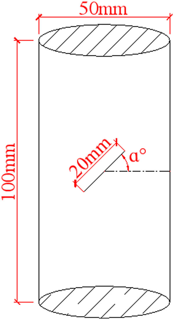
The experiment used yellow sandstone from Hunan, China. According to the method recommended by the international society of rock mechanics, the cylinder rock samples with the diameter of 50 mm and the height of 100 mm were generated [40]. In order to limit the impact of rock dispersion, rock samples with equal wave velocities and good homogeneity were chosen using ultrasonic testing. The common dip angle joints with a length of 20 mm were sawed with an emery wire, and the specimens were sorted into six groups based on the total rock mass and the dip angle
Specimen parameters (
The RMT-150B rock mechanics testing system was applied, which was designed by the Chinese Academy of Sciences’ Institute of Rock and Soil Mechanics, and the jointed rock mass specimens were subjected to uniaxial compression failure testing, as shown in Figure 2. The main parameters of the testing machine are as follows: the vertical cylinder piston stroke is 0–50 mm, the force sensor has a range of 1,000 kN with an accuracy of 5‰, the axial and lateral displacement sensors have respective ranges of 5 and 2.5 mm, with an accuracy of 1.5‰. Before the uniaxial compression experiment, butter was applied to the end face of the sample to reduce the influence of friction on the contact surface between the apparatus and the sample. During the test, the loading rate was applied at 0.5 MPa·s−1. The mechanical properties of the rock mass with different inclinations are shown in Table 1.
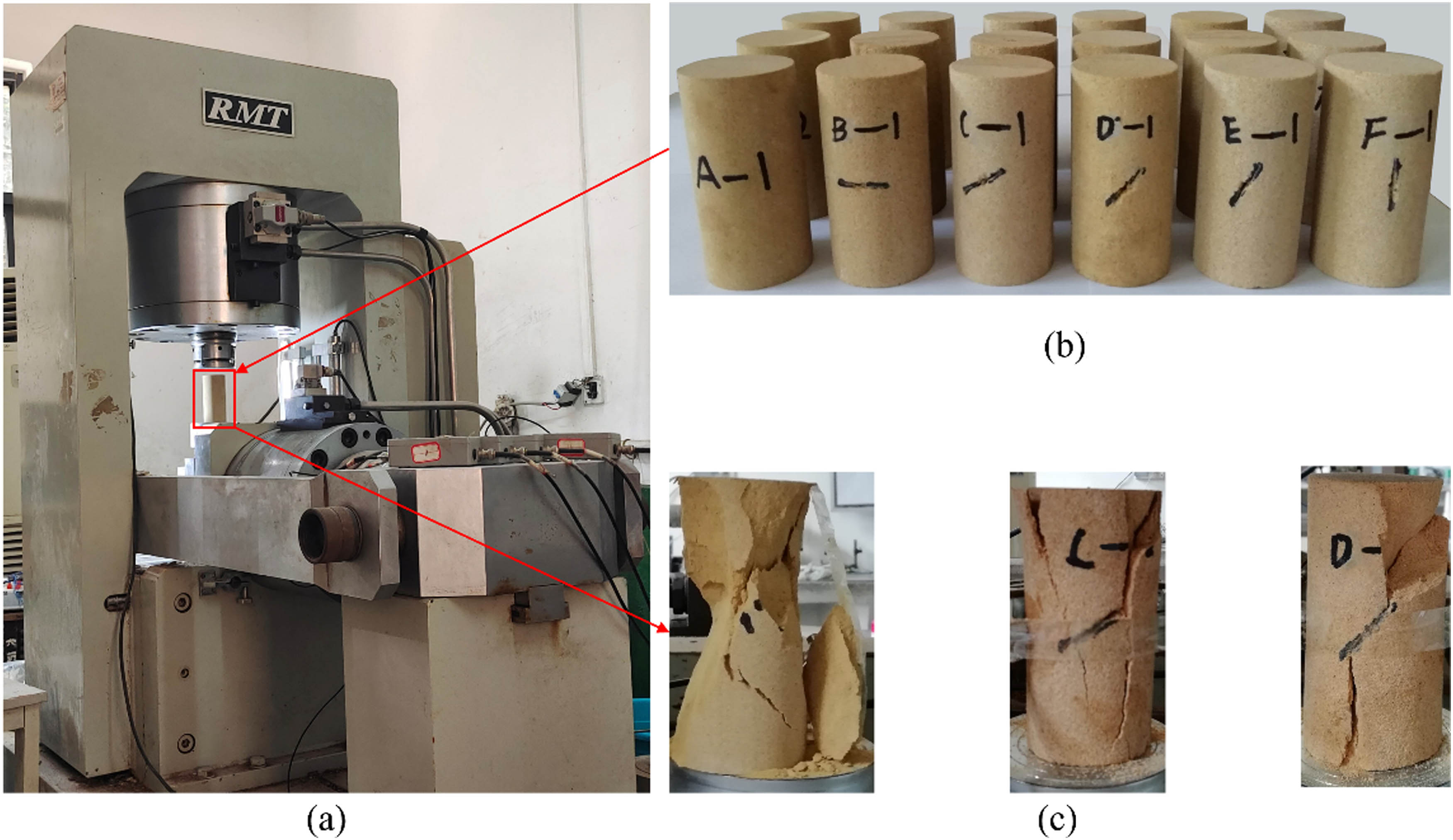
Uniaxial compression testing: (a) RMT-150B, (b) before compression, and (c) after compression.
Mechanical properties of jointed rock mass with different inclinations
| Joint inclination (°) |
|
Peak stress (MPa) | Peak strain (10−3) |
|---|---|---|---|
| Intact rock mass | 9.52 | 70.77 | 11.21 |
|
|
7.48 | 53.18 | 8.49 |
|
|
7.49 | 46.17 | 9.18 |
|
|
7.67 | 44.19 | 8.23 |
|
|
7.20 | 37.80 | 8.98 |
|
|
7.78 | 59.38 | 9.89 |
3.2 Damage characteristic analysis
3.2.1 Model validation
The damage constitutive model of jointed rock mass under uniaxial stress (Eq. (21)) was validated by the uniaxial compression test. Herein, the internal friction angle
where
Curve fitting is a typical method for determining the parameters of a constitutive model, which can make full use of experimental data to achieve the smallest possible total discrepancy between theoretical and experimental results [41]. Based on mechanical parameters of a rock mass with various inclination joints, Eq. (22) is used to perform nonlinear least-squares fitting, as shown in Figure 3, and the values of the model parameters are shown in Table 2.

Comparison of experimental and theoretical values of stress–strain curves: (a) intact rock mass, (b) β = 0°, (c) β = 30°, (d) β = 45°, (e) β = 60°, and (f) β = 90°.
Model parameters s, F 0, and n
| Joint inclination (°) |
|
|
|
|---|---|---|---|
| Intact rock mass | 0.0193 | 11.480 | 16.965 |
|
|
0.0125 | 24.499 | 12.554 |
|
|
0.0129 | 5.487 | 14.432 |
|
|
0.0130 | 9.580 | 12.850 |
|
|
0.0193 | 35.391 | 12.985 |
|
|
0.0165 | 36.896 | 14.194 |
As can be seen from Figure 3, the stress–strain curves can be separated into five stages. During the early loading phase, the joint surface and initial micro-cracks gradually close, the friction between the closed surfaces restricts the development and beginning of micro-cracks, and the strain develops rapidly, which is the compaction stage (Ⅰ). In the concave portion of the curve, it enters the nonlinear elastic stage (Ⅱ). The slope of the curve increases gradually and tends to be linear, and the rock mass enters the linear elastic stage (Ⅲ) from the nonlinear elastic stage as its deformation velocity slows and its stress–strain increases in equal steps. When stress redistribution gradually builds an effective load-bearing structure, the specimen structure continues to absorb external energy and store energy for later damage and failure, as seen by an upward concave curve, and the rock mass enters the yield stage (Ⅳ). After reaching the ultimate bearing capacity, the bearing structure of rock mass is continuously softened and enters the brittle failure stage (Ⅴ).
All correlation coefficients between stress–strain curves and fitting curves of jointed rock mass with varying inclinations are higher than 0.98. The result proves the constitutive model developed in this study can describe the compression, elastic, yield, and brittle failure stages of the stress–strain curve of a jointed rock mass during loading and indicates that the mechanical behavior, strength, and deformation law of rock mass under varying jointed inclinations could accurately predict.
3.2.2 Law of damage evolution
The jointed structural surface substantially impacts the deformation properties and failure law of rock mass. In order to further verify the rationality of the established model, the damage at the peak value is calculated by Eq. (18) according to the parameter values in Table 2, and its damage evolution characteristics are analyzed and verified through normalization. The peak strength and damage changes induced by jointed inclination are shown in Figure 4.

Relationship of peak stress and critical damage with jointed inclination.
As can be seen in Figure 4, under the coupling effect of structural features and load effect, the experimental peak value of jointed rock mass is the least at 60° and reaches the maximum at 90°, showing a “U”-shaped distribution rule in general. When the joint inclination angle increases from 0° to 30°, the absolute deviation marginally increases from 1.05 to 1.78 MPa, and the maximum deviation rate is 3.86%. The variation can be decreased through parameter adjustment, and it is vital to assess the parameter sensitivity in order to improve the precision of theoretical results. As the angle of inclination increases, the absolute deviation decreases to less than 1.0 MPa, the peak stress calculated theoretically corresponds to the experimental peak stress level, and the degree of coincidence is high.
The damage value at the peak of a mass of jointed rock with varying inclination is plainly distinct, and the variation rules for the damage value and peak strength value are diametrically opposed. The damage value is lowest when the joint inclination angle is 0° and increases to 0.88 from 0.61 as the joint inclination increases to 30°. While the joint inclination increases to 45°, the damage value increases to 0.79, which indicates that the compressive resistance of the rock mass structure has been enhanced. However, when the joint inclination is 60°, the damage value is maximum, and the peak strength of the jointed rock mass is lowest. The rock mass experiences shear slip failure along the joint surface and has a low failure resistance, which indicates that the shear force on the joint surface is more than the sum of friction force and cohesion force. In theory, this is consistent with the rock mass failure angle (
4 Discussion
The parameters

Stress–strain curve under different values of the parameters s, F
0, and n. (a)
The macro-damage parameter s of the model governs the overall shape of the stress–strain curve and exerts varied degrees of influence on the shape of the stress–strain curve at each stage, as shown in Figure 5(a). The parameter s increases with the gradient from 0.0133 to 0.0193, while peak stress declines by 13.07, 11.55, and 10.37%, respectively. The magnitude of the peak stress variation decreases, although the peak strain remains constant, and the rate of reduction during the post-peak phase is slowed. The microscopic damage parameter
Based on the change features of the stress–strain curve for various parameter values, it is evident that the stress–strain curve is highly sensitive to parameter s. Both stress–strain curves in Figure 5(b) and (c) exhibit evident bifurcation points. Simplify Eq. (22) into a negative exponential function whose value is close to 1 when ɛ is close to 0. Currently, the stress–strain curve is only related to the coefficient of the function, resulting in a coincident segment. A bifurcation point emerges as the value of the function without the coefficient component deviates from 1 as strain increases. Therefore, in the gradient change of parameter
5 Conclusions
As basic elements in mines, the study of the relationship between strength and deformation under load is all important for the rock mass. In this study, the damage constitutive model of jointed rock mass under the influence of structural features and load effect is developed, and the main conclusions are as follows.
The results calculated by the model correspond well with the stress–strain experimental results obtained by uniaxial compression for jointed rock masses with differing inclinations, which accurately described the stress–strain relationship of jointed rock masses with varying inclinations, thereby validating the rationality of the model.
The rock mass has the lowest resistance to failure and the highest damage value when the joint inclination is 60°. In this condition, the shear force on the joint surface exceeds the sum of friction and cohesion, resulting in shear slip failure along the joint surface. Therefore, this form of jointed and fractured rock mass requires special consideration in engineering.
The theoretical curve of the model is highly sensitive to the macroscopic damage parameter s, and the microscopic damage parameter
Acknowledgments
The authors would like to thank the National Natural Science Foundation for Young Scientists of China (Grant No. 51204098) and the Natural Science Foundation of Hunan (2021JJ30575). The authors also express their sincere gratitude to the editor and reviewers for their valuable comments, which have greatly improved this article.
-
Funding information: This work was supported by the National Natural Science Foundation for Young Scientists of China (Grant No. 51204098) and the Natural Science Foundation of Hunan (2021JJ30575). The authors are very grateful for the financial contributions and convey their appreciation to the organizations for supporting this basic research.
-
Author contributions: Bing Sun and Sheng Zeng: conceptualization, methodology; Peng Yang and Yu Luo: experiment, analysis, writing; Bo Deng checked the manuscript. All authors have accepted responsibility for the entire content of this manuscript and approved its submission.
-
Conflict of interest: The authors state no conflict of interest.
-
Data availability statement: The datasets generated and/or analyzed during the current study are available from the corresponding author on a reasonable request.
References
[1] Qin, Y. Discussion on damage mechanics model and constitutive equation of rock. Chinese Journal of Rock Mechanics and Engineering, Vol. 20, No. 4, 2001, pp. 560–562.Search in Google Scholar
[2] Kyoya, T., Y. Ichikawa, and T. Kawamoto. Damage mechanics theory for discontinuous rock mass. In: Proceedings of International Conference on Numerical Methods in Geomechanics, Nagoya, 1985, pp. 469–480.Search in Google Scholar
[3] Li, T. C., L. X. Lyu, S. L. Zhang, and J. C. Sun. Development and application of a statistical constitutive model of damaged rock affected by the load-bearing capacity of damaged elements. Journal of Zhejiang University-SCIENCE A, Vol. 16, 2015, pp. 644–655.10.1631/jzus.A1500034Search in Google Scholar
[4] Chen, Y., L. Zhang, H. Xie, J. F. Liu, H. Liu, and B. Q. Yang. Damage ratio based on statistical damage constitutive model for rock. Mathematical Problems in Engineering, Vol. 2019, 2019, id. 3065414.10.1155/2019/3065414Search in Google Scholar
[5] Chen, S., C. Qiao, Q. Ye, and M. U. Khan. Comparative study on three-dimensional statistical damage constitutive modified model of rock based on power function and Weibull distribution. Environmental Earth Sciences, Vol. 77, No. 3, 2018, pp. 1–8.10.1007/s12665-018-7297-6Search in Google Scholar
[6] Shen, P. W., H. M. Tang, Y. B. Ning, and D. Xia. A damage mechanics based on the constitutive model for strain-softening rocks. Engineering Fracture Mechanics, Vol. 216, 2019, id. 106521.10.1016/j.engfracmech.2019.106521Search in Google Scholar
[7] Liu, Y. and F. Dai. A damage constitutive model for intermittent jointed rocks under cyclic uniaxial compression. International Journal of Rock Mechanics and Mining Sciences, Vol. 103, 2018, pp. 289–301.10.1016/j.ijrmms.2018.01.046Search in Google Scholar
[8] Liu, H. Y. and F. J. Zhu. A damage constitutive model for the intermittent cracked rock mass under the planar complicated stress condition. Current Science, Vol. 115, No. 3, 2018, pp. 559–565.10.18520/cs/v115/i3/559-565Search in Google Scholar
[9] Wang, J., W. Song, and J. Fu. A damage constitutive model and strength criterion of rock mass considering the dip angle of joints. Chinese Journal of Rock Mechanics and Engineering, Vol. 37, No. 10, 2018, pp. 2253–2263.Search in Google Scholar
[10] Yang, W. D., G. Z. Li, P. G. Ranjith, and L. D. Fang. An experimental study of mechanical behavior of brittle rock-like specimens with multi-non-persistent joints under uniaxial compression and damage analysis. International Journal of Damage Mechanics, Vol. 28, No. 10, 2019, pp. 1490–1522.10.1177/1056789519832651Search in Google Scholar
[11] Xu, J., D. Fei, Y. Yu, Y. Cui, C. Yan, H. Bao, et al. Research on crack evolution law and macroscopic failure mode of joint Phyllite under uniaxial compression. Scientific Reports, Vol. 11, No. 1, 2021, pp. 1–18.10.1038/s41598-021-83571-9Search in Google Scholar PubMed PubMed Central
[12] Le, L. A., G. D. Nguyen, H. H. Bui, A. H. Sheikh, A. Kotousov, and A. Khanna. Modelling jointed rock mass as a continuum with an embedded cohesive-frictional model. Engineering Geology, Vol. 228, 2017, pp. 107–120.10.1016/j.enggeo.2017.07.011Search in Google Scholar
[13] Gao, W., C. Hu, T. He, X. Chen, C. Zhou, and S. Cui. Study on constitutive model of fractured rock mass based on statistical strength theory. Rock and Soil Mechanics, Vol. 41, No. 7, 2020, pp. 2179–2188.Search in Google Scholar
[14] Chen, Y., H. Lin, Y. Wang, S. Xie, Y. Zhao, and W. Yong. Statistical damage constitutive model based on the Hoek–Brown criterion. Archives of Civil and Mechanical Engineering, Vol. 21, No. 3, 2021, pp. 1–9.10.1007/s43452-021-00270-ySearch in Google Scholar
[15] Chen, S., X. Cao, and Z. Yang. Three dimensional statistical damage constitutive model of rock based on Griffith strength criterion. Geotechnical and Geological Engineering, Vol. 39, No. 8, 2021, pp. 5549–5557.10.1007/s10706-021-01844-6Search in Google Scholar
[16] Li, Y., H. Zhang, M. Chen, X. Meng, Y. Shen, H. Liu, et al. Strength criterion of rock mass considering the damage and effect of joint dip angle. Scientific Reports, Vol. 12, No. 1, 2022, pp. 1–14.10.1038/s41598-022-06317-1Search in Google Scholar PubMed PubMed Central
[17] Li, F., S. You, H. Ji, and H. Wang. Study of damage constitutive model of brittle rocks considering stress dropping characteristics. Advances in Civil Engineering, Vol. 2020, 2020, id. 8875029.10.1155/2020/8875029Search in Google Scholar
[18] Wang, Z. L., Y. C. Li, and J. G. Wang. A damage-softening statistical constitutive model considering rock residual strength. Computers & Geosciences, Vol. 33, No. 1, 2007, pp. 1–9.10.1016/j.cageo.2006.02.011Search in Google Scholar
[19] Wen, T., Y. Liu, C. Yang, and X. Yi. A rock damage constitutive model and damage energy dissipation rate analysis for characterising the crack closure effect. Geomechanics and Geoengineering, Vol. 13, No. 1, 2018, pp. 54–63.10.1080/17486025.2017.1330969Search in Google Scholar
[20] Hu, B., Z. Zhang, J. Li, H. Xiao, and Z. Wang. Statistical damage model of rock structural plane considering void compaction and failure modes. Symmetry, Vol. 14, No. 3, 2022, pp. 434–447.10.3390/sym14030434Search in Google Scholar
[21] Zhang, C., J. Yu, Y. Bai, W. G. Cao, S. Zhang, and Z. G. Guo. Statistical damage constitutive model of rock brittle-ductile transition based on strength theory. Chinese Journal of Rock Mechanics and Engineering, Vol. 42, No. 02, 2023, pp. 307–316.Search in Google Scholar
[22] Cao, W. G., X. Tan, C. Zhang, and H. Min. A constitutive model to simulate full deformation and failure process for rocks considering initial compression and residual strength behaviors. Canadian Geotechnical Journal, Vol. 56, No. 5, 2019, pp. 649–661.10.1139/cgj-2018-0178Search in Google Scholar
[23] Li, X., H. Chen, and J. Zhang. Statistical damage model for whole deformation and failure process of rock considering initial void closure. Journal of Southwest Jiaotong University, Vol. 57, No. 2, 2022, pp. 314–321.Search in Google Scholar
[24] Peng, Z., Y. Zeng, X. Chen, and S. Cheng. A macro–micro damage model for rock under compression loading. Applied Sciences, Vol. 11, No. 24, 2021, pp. 12154–12172.10.3390/app112412154Search in Google Scholar
[25] Liu, H., L. Li, S. Zhao, and S. Hu. Complete stress–strain constitutive model considering crack model of brittle rock. Environmental Earth Sciences, Vol. 78, No. 21, 2019, pp. 1–18.10.1007/s12665-019-8643-zSearch in Google Scholar
[26] Liu, X. S., J. G. Ning, Y. L. Tan, and Q. H. Gu. Damage constitutive model based on energy dissipation for intact rock subjected to cyclic loading. International Journal of Rock Mechanics and Mining Sciences, Vol. 85, 2016, pp. 27–32.10.1016/j.ijrmms.2016.03.003Search in Google Scholar
[27] Ma, Q., Y. L. Tan, X. S. Liu, Q. H. Gu, and X. B. Li. Effect of coal thicknesses on energy evolution characteristics of roof rock-coal-floor rock sandwich composite structure and its damage constitutive model. Composites Part B Engineering, Vol. 198, 2020, id. 108086.10.1016/j.compositesb.2020.108086Search in Google Scholar
[28] Liang, M., S. Miao, M. Cai, Z. Huang, and P. Yang. A damage constitutive model of rock with consideration of dilatation and postpeak shape of the stress-strain curve. Chinese Journal of Rock Mechanics and Engineering, Vol. 40, No. 12, 2021, pp. 2392–2401.Search in Google Scholar
[29] Cao, R. L., S. H. He, J. Wei, and F. Wang. Study of modified statistical damage softening constitutive model for rock considering residual strength. Rock and Soil Mechanics, Vol. 34, No. 6, 2013, pp. 1652–1660+1667.Search in Google Scholar
[30] Zhao, H., C. J. Shi, M. H. Zhao, and X. B. Li. Statistical damage constitutive model for rocks considering residual strength. International Journal of Geomechanics, Vol. 17, No. 17, 2017, id. 04016033.10.1061/(ASCE)GM.1943-5622.0000680Search in Google Scholar
[31] Deng, J. and D. Gu. On a statistical damage constitutive model for rock materials. Computers & Geosciences, Vol. 2011, No. 37, 2011, pp. 122–128.10.1016/j.cageo.2010.05.018Search in Google Scholar
[32] Zhou, C., M. Karakus, C. Xu, and J. Shen. A new damage model accounting the effect of joint orientation for the jointed rock mass. Arabian Journal of Geosciences, Vol. 13, No. 7, 2020, pp. 1–13.10.1007/s12517-020-5274-3Search in Google Scholar
[33] Liu, D. Q., M. C. He, and M. Cai. A damage model for modeling the complete stress-strain relations of brittle rocks under uniaxial compression. International Journal of Damage Mechanics, Vol. 27, No. 7, 2018, pp. 1000–1019.10.1177/1056789517720804Search in Google Scholar
[34] Peng, J., G. Rong, M. Cai, and C. B. Zhou. A model for characterizing crack closure effect of rocks. Engineering Geology, Vol. 189, 2015, pp. 48–57.10.1016/j.enggeo.2015.02.004Search in Google Scholar
[35] Brace, W. F. An extension of the Griffith theory of fracture to rocks. Journal of Geophysical Research, Vol. 65, 1960, pp. 3477–3480.10.1029/JZ065i010p03477Search in Google Scholar
[36] Lin, H., J. Feng, R. Cao, and S. Xie. Comparative analysis of rock damage models based on different distribution functions. Geotechnical and Geological Engineering, Vol. 40, No. 1, 2022, pp. 301–310.10.1007/s10706-021-01899-5Search in Google Scholar
[37] Li, X., W. G. Cao, and Y. H. Su. A statistical damage constitutive model for softening behavior of rocks. Engineering Geology, Vol. 143, 2012, pp. 1–17.10.1016/j.enggeo.2012.05.005Search in Google Scholar
[38] Liu, H., S. Lv, Z. DanZeng, and J. Zhang. Study on 3-D constitutive model for jointed rock mass by coupling macroscopic and microscopic damage. Journal of Water Resources Architecture Engineering, Vol. 11, No. 3, 2013, pp. 85–88.Search in Google Scholar
[39] Li, X., C. Qi, Z. Shao, and C. Ma. Evaluation of strength and failure of brittle rock containing initial cracks under lithospheric conditions. Acta Geophysica, Vol. 66, No. 2, 2018, pp. 141–152.10.1007/s11600-018-0123-4Search in Google Scholar
[40] Fairhurst, C. E. and J. A. Hudson. Draft ISRM suggested method for the complete stress-strain curve for intact rock in uniaxial compression. International Journal of Rock Mechanics and Mining Sciences, Vol. 36, No. 3, 1999, pp. 279–289.Search in Google Scholar
[41] Zhang, Z., X. Zhu, and X. Liu. Study on creep characteristics and constitutive model of peridotite. Chinese Journal of Rock Mechanics and Engineering, Vol. 41, No. 8, 2022, pp. 1525–1535.Search in Google Scholar
© 2023 the author(s), published by De Gruyter
This work is licensed under the Creative Commons Attribution 4.0 International License.
Articles in the same Issue
- Review Articles
- Progress in preparation and ablation resistance of ultra-high-temperature ceramics modified C/C composites for extreme environment
- Solar lighting systems applied in photocatalysis to treat pollutants – A review
- Technological advances in three-dimensional skin tissue engineering
- Hybrid magnesium matrix composites: A review of reinforcement philosophies, mechanical and tribological characteristics
- Application prospect of calcium peroxide nanoparticles in biomedical field
- Research progress on basalt fiber-based functionalized composites
- Evaluation of the properties and applications of FRP bars and anchors: A review
- A critical review on mechanical, durability, and microstructural properties of industrial by-product-based geopolymer composites
- Multifunctional engineered cementitious composites modified with nanomaterials and their applications: An overview
- Role of bioglass derivatives in tissue regeneration and repair: A review
- Research progress on properties of cement-based composites incorporating graphene oxide
- Properties of ultra-high performance concrete and conventional concrete with coal bottom ash as aggregate replacement and nanoadditives: A review
- A scientometric review of the literature on the incorporation of steel fibers in ultra-high-performance concrete with research mapping knowledge
- Weldability of high nitrogen steels: A review
- Application of waste recycle tire steel fibers as a construction material in concrete
- Wear properties of graphene-reinforced aluminium metal matrix composite: A review
- Experimental investigations of electrodeposited Zn–Ni, Zn–Co, and Ni–Cr–Co–based novel coatings on AA7075 substrate to ameliorate the mechanical, abrasion, morphological, and corrosion properties for automotive applications
- Research evolution on self-healing asphalt: A scientometric review for knowledge mapping
- Recent developments in the mechanical properties of hybrid fiber metal laminates in the automotive industry: A review
- A review of microscopic characterization and related properties of fiber-incorporated cement-based materials
- Comparison and review of classical and machine learning-based constitutive models for polymers used in aeronautical thermoplastic composites
- Gold nanoparticle-based strategies against SARS-CoV-2: A review
- Poly-ferric sulphate as superior coagulant: A review on preparation methods and properties
- A review on ceramic waste-based concrete: A step toward sustainable concrete
- Modification of the structure and properties of oxide layers on aluminium alloys: A review
- A review of magnetically driven swimming microrobots: Material selection, structure design, control method, and applications
- Polyimide–nickel nanocomposites fabrication, properties, and applications: A review
- Design and analysis of timber-concrete-based civil structures and its applications: A brief review
- Effect of fiber treatment on physical and mechanical properties of natural fiber-reinforced composites: A review
- Blending and functionalisation modification of 3D printed polylactic acid for fused deposition modeling
- A critical review on functionally graded ceramic materials for cutting tools: Current trends and future prospects
- Heme iron as potential iron fortifier for food application – characterization by material techniques
- An overview of the research trends on fiber-reinforced shotcrete for construction applications
- High-entropy alloys: A review of their performance as promising materials for hydrogen and molten salt storage
- Effect of the axial compression ratio on the seismic behavior of resilient concrete walls with concealed column stirrups
- Research Articles
- Effect of fiber orientation and elevated temperature on the mechanical properties of unidirectional continuous kenaf reinforced PLA composites
- Optimizing the ECAP processing parameters of pure Cu through experimental, finite element, and response surface approaches
- Study on the solidification property and mechanism of soft soil based on the industrial waste residue
- Preparation and photocatalytic degradation of Sulfamethoxazole by g-C3N4 nano composite samples
- Impact of thermal modification on color and chemical changes of African padauk, merbau, mahogany, and iroko wood species
- The evaluation of the mechanical properties of glass, kenaf, and honeycomb fiber-reinforced composite
- Evaluation of a novel steel box-soft body combination for bridge protection against ship collision
- Study on the uniaxial compression constitutive relationship of modified yellow mud from minority dwelling in western Sichuan, China
- Ultrasonic longitudinal torsion-assisted biotic bone drilling: An experimental study
- Green synthesis, characterizations, and antibacterial activity of silver nanoparticles from Themeda quadrivalvis, in conjugation with macrolide antibiotics against respiratory pathogens
- Performance analysis of WEDM during the machining of Inconel 690 miniature gear using RSM and ANN modeling approaches
- Biosynthesis of Ag/bentonite, ZnO/bentonite, and Ag/ZnO/bentonite nanocomposites by aqueous leaf extract of Hagenia abyssinica for antibacterial activities
- Eco-friendly MoS2/waste coconut oil nanofluid for machining of magnesium implants
- Silica and kaolin reinforced aluminum matrix composite for heat storage
- Optimal design of glazed hollow bead thermal insulation mortar containing fly ash and slag based on response surface methodology
- Hemp seed oil nanoemulsion with Sapindus saponins as a potential carrier for iron supplement and vitamin D
- A numerical study on thin film flow and heat transfer enhancement for copper nanoparticles dispersed in ethylene glycol
- Research on complex multimodal vibration characteristics of offshore platform
- Applicability of fractal models for characterising pore structure of hybrid basalt–polypropylene fibre-reinforced concrete
- Influence of sodium silicate to precursor ratio on mechanical properties and durability of the metakaolin/fly ash alkali-activated sustainable mortar using manufactured sand
- An experimental study of bending resistance of multi-size PFRC beams
- Characterization, biocompatibility, and optimization of electrospun SF/PCL composite nanofiber films
- Morphological classification method and data-driven estimation of the joint roughness coefficient by consideration of two-order asperity
- Prediction and simulation of mechanical properties of borophene-reinforced epoxy nanocomposites using molecular dynamics and FEA
- Nanoemulsions of essential oils stabilized with saponins exhibiting antibacterial and antioxidative properties
- Fabrication and performance analysis of sustainable municipal solid waste incineration fly ash alkali-activated acoustic barriers
- Electrostatic-spinning construction of HCNTs@Ti3C2T x MXenes hybrid aerogel microspheres for tunable microwave absorption
- Investigation of the mechanical properties, surface quality, and energy efficiency of a fused filament fabrication for PA6
- Experimental study on mechanical properties of coal gangue base geopolymer recycled aggregate concrete reinforced by steel fiber and nano-Al2O3
- Hybrid bio-fiber/bio-ceramic composite materials: Mechanical performance, thermal stability, and morphological analysis
- Experimental study on recycled steel fiber-reinforced concrete under repeated impact
- Effect of rare earth Nd on the microstructural transformation and mechanical properties of 7xxx series aluminum alloys
- Color match evaluation using instrumental method for three single-shade resin composites before and after in-office bleaching
- Exploring temperature-resilient recycled aggregate concrete with waste rubber: An experimental and multi-objective optimization analysis
- Study on aging mechanism of SBS/SBR compound-modified asphalt based on molecular dynamics
- Evolution of the pore structure of pumice aggregate concrete and the effect on compressive strength
- Effect of alkaline treatment time of fibers and microcrystalline cellulose addition on mechanical properties of unsaturated polyester composites reinforced by cantala fibers
- Optimization of eggshell particles to produce eco-friendly green fillers with bamboo reinforcement in organic friction materials
- An effective approach to improve microstructure and tribological properties of cold sprayed Al alloys
- Luminescence and temperature-sensing properties of Li+, Na+, or K+, Tm3+, and Yb3+ co-doped Bi2WO6 phosphors
- Effect of molybdenum tailings aggregate on mechanical properties of engineered cementitious composites and stirrup-confined ECC stub columns
- Experimental study on the seismic performance of short shear walls comprising cold-formed steel and high-strength reinforced concrete with concealed bracing
- Failure criteria and microstructure evolution mechanism of the alkali–silica reaction of concrete
- Mechanical, fracture-deformation, and tribology behavior of fillers-reinforced sisal fiber composites for lightweight automotive applications
- UV aging behavior evolution characterization of HALS-modified asphalt based on micro-morphological features
- Preparation of VO2/graphene/SiC film by water vapor oxidation
- A semi-empirical model for predicting carbonation depth of RAC under two-dimensional conditions
- Comparison of the physical properties of different polyimide nanocomposite films containing organoclays varying in alkyl chain lengths
- Effects of freeze–thaw cycles on micro and meso-structural characteristics and mechanical properties of porous asphalt mixtures
- Flexural performance of a new type of slightly curved arc HRB400 steel bars reinforced one-way concrete slabs
- Alkali-activated binder based on red mud with class F fly ash and ground granulated blast-furnace slag under ambient temperature
- Facile synthesis of g-C3N4 nanosheets for effective degradation of organic pollutants via ball milling
- DEM study on the loading rate effect of marble under different confining pressures
- Conductive and self-cleaning composite membranes from corn husk nanofiber embedded with inorganic fillers (TiO2, CaO, and eggshell) by sol–gel and casting processes for smart membrane applications
- Laser re-melting of modified multimodal Cr3C2–NiCr coatings by HVOF: Effect on the microstructure and anticorrosion properties
- Damage constitutive model of jointed rock mass considering structural features and load effect
- Thermosetting polymer composites: Manufacturing and properties study
- CSG compressive strength prediction based on LSTM and interpretable machine learning
- Axial compression behavior and stress–strain relationship of slurry-wrapping treatment recycled aggregate concrete-filled steel tube short columns
- Space-time evolution characteristics of loaded gas-bearing coal fractures based on industrial μCT
- Dual-biprism-based single-camera high-speed 3D-digital image correlation for deformation measurement on sandwich structures under low velocity impact
- Effects of cold deformation modes on microstructure uniformity and mechanical properties of large 2219 Al–Cu alloy rings
- Basalt fiber as natural reinforcement to improve the performance of ecological grouting slurry for the conservation of earthen sites
- Interaction of micro-fluid structure in a pressure-driven duct flow with a nearby placed current-carrying wire: A numerical investigation
- A simulation modeling methodology considering random multiple shots for shot peening process
- Optimization and characterization of composite modified asphalt with pyrolytic carbon black and chicken feather fiber
- Synthesis, characterization, and application of the novel nanomagnet adsorbent for the removal of Cr(vi) ions
- Multi-perspective structural integrity-based computational investigations on airframe of Gyrodyne-configured multi-rotor UAV through coupled CFD and FEA approaches for various lightweight sandwich composites and alloys
- Influence of PVA fibers on the durability of cementitious composites under the wet–heat–salt coupling environment
- Compressive behavior of BFRP-confined ceramsite concrete: An experimental study and stress–strain model
- Interval models for uncertainty analysis and degradation prediction of the mechanical properties of rubber
- Preparation of PVDF-HFP/CB/Ni nanocomposite films for piezoelectric energy harvesting
- Frost resistance and life prediction of recycled brick aggregate concrete with waste polypropylene fiber
- Synthetic leathers as a possible source of chemicals and odorous substances in indoor environment
- Mechanical properties of seawater volcanic scoria aggregate concrete-filled circular GFRP and stainless steel tubes under axial compression
- Effect of curved anchor impellers on power consumption and hydrodynamic parameters of yield stress fluids (Bingham–Papanastasiou model) in stirred tanks
- All-dielectric tunable zero-refractive index metamaterials based on phase change materials
- Influence of ultrasonication time on the various properties of alkaline-treated mango seed waste filler reinforced PVA biocomposite
- Research on key casting process of high-grade CNC machine tool bed nodular cast iron
- Latest research progress of SiCp/Al composite for electronic packaging
- Special Issue on 3D and 4D Printing of Advanced Functional Materials - Part I
- Molecular dynamics simulation on electrohydrodynamic atomization: Stable dripping mode by pre-load voltage
- Research progress of metal-based additive manufacturing in medical implants