Evaluation of a novel steel box-soft body combination for bridge protection against ship collision
-
Hongfei Yan
 ,
Lu Zhu
,
Lu Zhu

Abstract
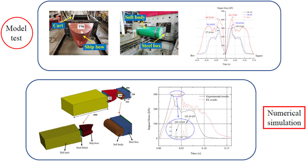
Ship–bridge collision is a common type of accident in bridge engineering which could cause heavy casualties and economic losses. To ensure the safety of both the ships and bridges during collision, a novel steel box-soft body combination was proposed in this work. The time history curves of the impact force of three downscaled facility specimens were obtained through the horizontal impact test. The influence of the steel box web spacing and the existence of the anti-collision facilities on the ship collision force reduction rate was investigated. The collision failure modes of ship bow and the anti-collision facilities, as well as the energy absorption behavior of the facility were analyzed. Based on ANSYS/LS-DYNA finite element (FE) analysis software, the nonlinear numerical models of the anti-collision facilities were generated. The analysis results show that the proposed anti-collision facility can not only greatly reduce the ship impact force, but the bow damage as well. The densified steel box web can improve the anti-collision performance of the whole anti-collision facilities to a certain extent. Compared with the direct impact on the steel plate, the maximum reduction rate of peak force of the proposed facility can be achieved to be 31.07%. The anti-collision facilities deformation energy absorption accounts for more than 70% of the total energy, which shows that the facility is able to absorb most of the energy and protect the bow. The FE simulation results coincide with the experimental outcomes, indicating the acceptable accuracy of the FE models.
Graphical abstract
1 Introduction
The transportation industry on waterway has developed rapidly in recent years. Various kinds of ship–bridge collision accidents occur, which cause a serious impact on architecture and society [1]. To ensure the safety of both the ships and bridges, anti-collision facilities were commonly adopted as practical engineering solution.
There exist many types of traditional anti-collision facilities. Composite materials have been applied to anti-collision systems recently, which achieved good results and showed promising application prospects. In order to alleviate the damage caused by ship impacting with the bridge pier, Fang et al. [2] proposed a large-scale composite bumper system (LCBS). Glass fiber-reinforced polymer (GFRP) was used in the modular segment of LCBS. Zhu et al. [3] put forward a novel fiber-reinforced polymer foam-filled lattice composite bumper system and used it as a bridge pier to resist ship collision and protect bridge structure. Wang et al. [4] evaluated a composite anti-collision facility. Important material parameters of GFRP have been clarified. All these systems have been proved to have good energy dissipation capacity and can effectively protect piers and ships through both experimental and FE numerical analysis way.
Up to now, several facilities with different kinds of materials were proposed by other scholars and their anti-collision characteristics were studied. Various anti-collision facilities are combined to give full play to their performance advantages [5,6,7,8,9]. For example, Shan et al. [10] proposed a kind of composite anti-collision box with steel-polyurethane (PU) sandwich plates as the structural material. Its panel was mainly designed for resisting impact force, and the sandwich structure was mainly used for receiving and transmitting the shear force. The circular curved box can rotate around the central point during impact, making the bow of the ship easier to deflect and avoid severe frontal collision. Composite fender structure [11,12] was proposed to resist ship impact, and its effectiveness was examined. The feasibility was verified through model test [13,14], numerical simulation [15], and some novel, fast, and general analytical procedures [16,17].
Several scholars have studied the energy absorption behavior of hollow or composite filled circular tubes under quasi-static or impact loads. For the research on composite cylinder, Niknejad et al. [18,19] carried out the experimental study on the tube filled with PU foam with lateral quasi-static loading conditions. The PU foam was proved to be effective on improving the bearing capacity and energy absorption value of the tube under lateral pressure. Liu et al. [20] used two rigid plates to conduct quasi-static transverse compression of aluminum foam-filled and empty circular tubes. The deformation modes of the circular tube filled with aluminum foam were verified to be changed and the energy absorption capacity was increased. Ujihashi et al. [21] studied the energy absorption performance of thin-walled cylinder with carbon fiber reinforced polymer (CFRP) under impact load. The results showed that CFRP can be used as an effective energy absorption material, but the resin strength will be greatly reduced in high temperature. The above research is an important reference for the impact energy absorption test and mechanism research of soft body with filler in this work.
The rigid anti-collision facilities represented by steel boxes can absorb high collision energy with their deformable plastic zone [22,23]. However, it will cause great damage to the ship. At present, most of the anti-collision facilities are flexible. However, for the impact of large tonnage ships, the simple flexible anti-collision facilities cannot meet the engineering needs. Based on the design principle that the ship directly impacts with soft body, a steel box-soft body combination anti-collision system is proposed in this work, as shown in Figure 1b. The proposed facility can be designed and installed on the pier and float up and down with the water level and its schematic diagram is shown in Figure 1a. The dynamic response and deformation modes of the anti-collision facilities were analyzed when subjected to impact load [24,25,26], and its performance [27] was also explored in the current study.
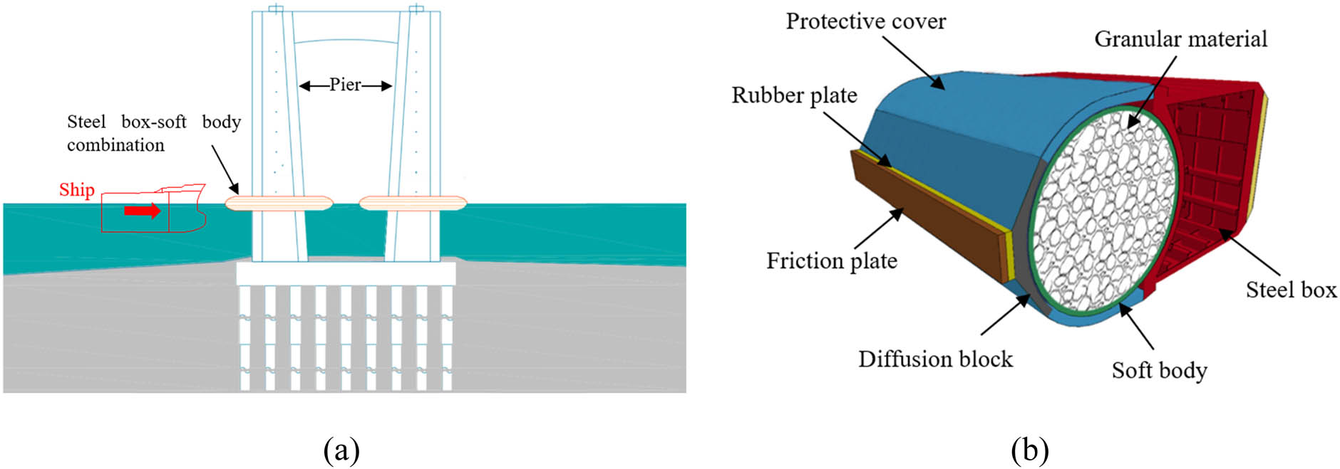
(a) Installation diagram of steel box-soft body combination and (b) segment of steel box-soft body combination.
2 Configuration of soft body
The flexible soft body part is mainly composed of soft body cavity, granular material, and protective cover. Fiber-reinforced resin matrix composite anti-collision system has good energy absorption performance [28,29], but it is easy to produce unrecoverable deformation when impacted with a vessel. In addition, the maintenance is difficult, and the cost is high. So, in this work, the cylindrical or semicylindrical shaped soft body cavity is made of thin-walled soft material with highly elastic fiber or high-strength steel wire reinforced rubber composite. Rubber layer is generally divided into three layers: outer layer, sandwich layer, and inner layer (Figure 2a). This composite material has the advantages of strong designability, good elasticity, excellent corrosion resistance, and convenient transportation and installation. At present, it is widely used in many fields. Take rubber dam as an example, the fiber reinforced materials in the rubber dam bear the main force, as shown in Figure 2b. The cost of rubber dam is more than 70% lower than that of ordinary dam, and its construction period is much shorter than that of ordinary dam. All these show the remarkable advantages of the soft body anti-collision structure. Combined with the principle of boxing sandbags (Figure 2c), the soft body anti-collision system is designed. The granular material is densely filled in the soft body cavity, which plays a major role in energy consumption. The interaction between the soft body cavity and granular material can be considered as a nonlinear spring connection (Figure 2d). The protective cover is wrapped outside the soft body cavity to protect it.

(a) Soft body layer with fiber-reinforced rubber composite, (b) fiber-reinforced rubber dam, (c) sandbag, and (d) the interaction between soft body cavity and granular material.
3 Experimental section
3.1 Specimen design
Taking the web spacing of steel box and the presence or absence of anti-collision facilities as test parameters, three specimens were designed. The model construction of anti-collision facilities is shown in Figure 3, in which the diameter of the soft body was 300 mm, the width of the steel box was 800 mm, the thickness of the steel plate for the steel box was 5 mm, and the height was 320 mm. Moreover, the thickness of the fiber-reinforced rubber composites was 5 mm, which were composed of fiber cloth and rubber. Ceramsite with particle size less than 10 mm was adopted. The whole manufacturing process of anti-collision facilities is depicted in Figure 4.

Model construction of anti-collision facilities (units: mm): (a) cross section and (b) 1–1 diagram.
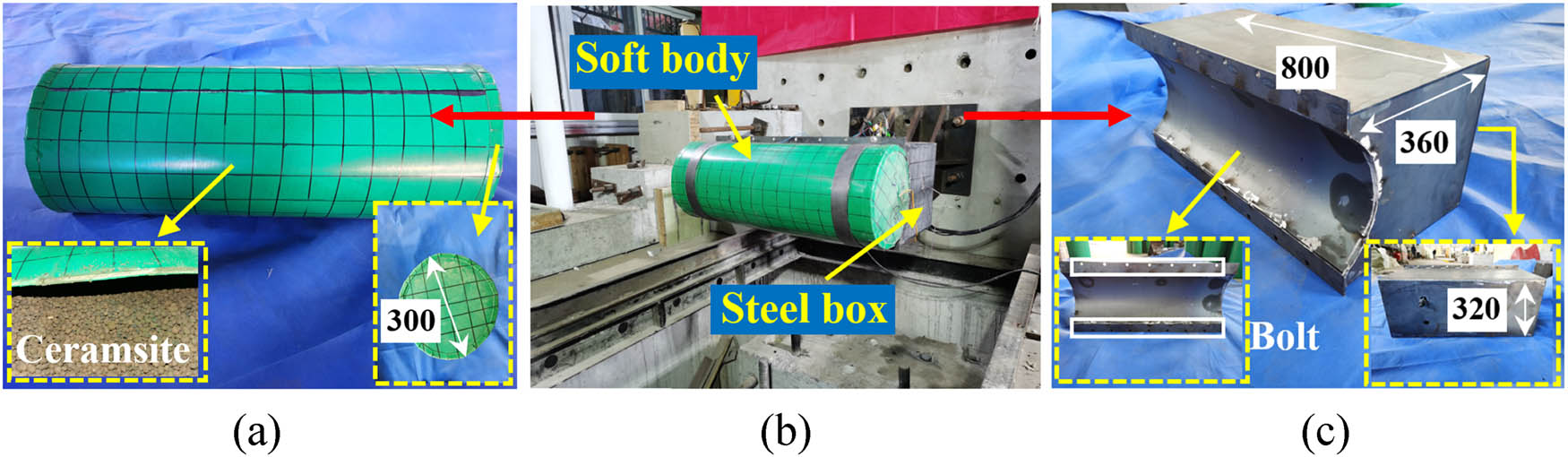
Manufacturing process of anti-collision facilities: (a) soft body (units: mm), (b) steel box-soft body combination, and (c) steel box (units: mm).
When a ship collides with a pier, the hull deforms, which is a very complex nonlinear process. Due to the high cost of full-scale test, scaled test is often used for research. It was very difficult to restore the real ship structure, so the simplified model of steel bow was used in the current tests. The model was downscaled to 1:10 compared with the prototype and it was welded with the impact rigid cart. Since it was difficult to ensure that the ship model was geometrically similar to the prototype ship, the steel plate with the same material properties as the ship was utilized to make the model. The stiffener in the actual hull was simplified based on the equivalent bending stiffness, and the thickness of the bow steel plate was selected as 2 mm. To prevent the bending moment of the back plate from affecting the test results, the back plate was thickened to 15 mm to increase the contact areas. The prototype of the ship was a 10,000 DWT cargo ship. In the current test, the ship’s weight, speed, and the total weight of the rigid cart and bow are 13,550 kg, 2.26 m·s−1, and 2,668 kg, respectively. Based on the principle of kinetic energy, which is equivalent to energy (Eq. (1)), the impact speed was calculated as 5.09 m·s−1. The main similarity ratio of the tests in this work is summarized in Table 1. Figure 5 shows the bow model.
where a stands for ship, b stands for impact rigid cart.
Main similarity ratio of impact model test
| Type | Physical quantity | Dimension | Similarity coefficient | Similarity ratio (10,000 DWT) |
|---|---|---|---|---|
| Geometric properties | Length | [L] | S L | 1/10 |
| Linear displacement | [L] | S L | 0.1 | |
| Material properties | Stress | [ML −1 T −2] | S E | 1 |
| Strain | — | 1 | 1 | |
| Elastic modulus | [ML −1 T −2] | S E | 1 | |
| Poisson’s ratio | — | 1 | 1 | |
| Load characteristics | Concentrated force | [MLT −2] | S E S L 2 | 0.01 |
| Dynamic characteristics | Mass | [M] | S ρ S L 3 | 0.001 |
| Velocity | [LT −1] |
|
1 |
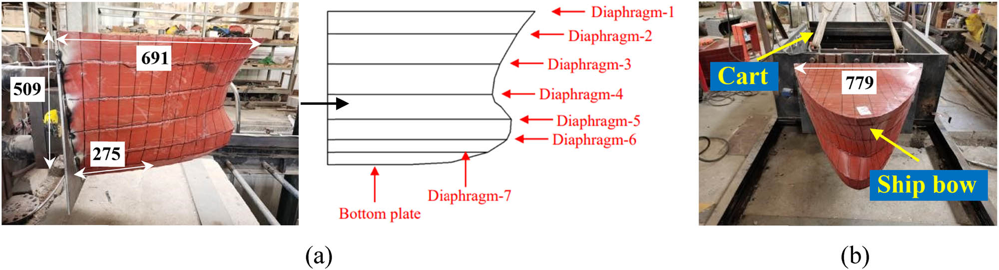
Ship bow model (units: mm): (a) side view and (b) overall view.
3.2 Quasi-static compression test
3.2.1 Experimental setup scheme
The quasi-static compression test of the steel ship bow was conducted at Nanjing Tech University using large load-shear test machine (YAW-10000 J). The resolution of the force measurement for the test machine is 0.5 N while the displacement is 0.01 mm. The square loading header was adopted to simulate the rigid wall, which was loaded vertically down on the bow. Before the start of the main test, a trial specimen was used to pre load to 20–30 kN. Then, the prepared specimen was replaced and installed. The displacement was used to control the loading rate, which was 5 mm·min−1. The displacement was controlled to 300 mm. The specimen was loaded continuously until it was damaged.
3.2.2 Analysis of experimental results
Figure 6 shows the failure modes. Figure 7 shows the load–displacement curve of the bow. When the pressing depth of the loading header reached 107.52 mm, the peak value of reaction force measured was 162.35 kN. When the loading header contacted with the bow, the top area of the bow deformed first. When the loading header was pressed into the depth of 12 mm, the first wrinkles on steel plate appeared at the connection between the upper deck and the peak cabin of the bow. With the gradual increase in the pressed depth, the steel plate gradually began to buckle and deform. Material bending and folding sound was spotted, the wrinkles on ship hull plate were also gradually increased. When the pressed depth reached 300 mm, many small cracks appeared at the welding position of the hull plate. At the displacement of 15 mm, 48 mm, 70 mm, and other positions, there are obvious unloading falling sections in the curve. During the test, the steel plate was crushed and fractured at those positions, which was the reason for the fracture of the local welding points between the internal diaphragm plates and the external steel plates.

Quasi-static compression test (compression amount of 300 mm moment).

Load–displacement curve of the bow under the quasi-static compression test.
3.3 Horizontal impact test
3.3.1 Experimental setup scheme and acquisition system
The test was performed by using the 230 kJ impact test machine at Nanjing Tech University. The horizontal impact test system mainly consisted of an impact cart, a reaction frame and a reaction wall. The DTM2234-11 drop-hammer machine is capable of being lifted up to 20 m high, with a maximum impact energy of 230 kJ. The gravitational potential energy is transformed into kinetic energy by the free-fall of the drop hammer. One side of the steel rope was attached to the drop hammer, and the other side was attached to the cart-pulling device. After lifting the drop hammer to a specified height, the steel rope decoupled and separated from the cart, and the cart hit the specimen at a certain speed. The mass of the cart is 1,582 kg, and the impact point is 600 mm away from the top surface of the footing. The size of the rigid impact head at the front end of the cart is 580 × 200 × 100 mm3. Figures 8 and 9 illustrate the layout of the horizontal impact test.

Schematic diagram of the horizontal impact test.
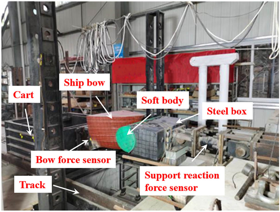
Layout of the horizontal impact test.
Horizontal impact force and velocity would be measured. The dynamic data collecting system included force sensor, speed collector, charge amplifier, data acquisition box, etc. The impact force is acquired based on the transformation of strain change on the force sensor, with expertise of 0.5 and inherent frequency of 200 kHz. The signal is amplified by DH3840 programmable strain amplifier and then input to the dynamic data acquisition instrument. The resolution of speed data collection is 0.5, which is measured by double laser. The impact process is captured by a high-speed camera, Sony NEX-FS700RH, with frames per second of 400 fps.
3.3.2 Test phenomenon
The specific test specimens are listed in Table 2.
Specifications of the test specimens
| Label | Web spacing of steel box | Ship tonnage | Combined form | Specimen number |
|---|---|---|---|---|
| GR-160 | 160 mm (five web plates) | 10,000 DWT | Steel box + soft body | 1 |
| GR-200 | 200 mm (four web plates) | 10,000 DWT | Steel box + soft body | 1 |
| G-A | / | 10,000 DWT | 800 × 320 mm2 steel plate | 1 |
Note: G stands for rigid body and R for soft body. 160 and 200 stand for the web spacing of steel box, which is 160 and 200 mm, respectively.
The test phenomena of each specimen are introduced as follows.
3.3.2.1 GR-160
The actual impact speed of the cart measured in the test was 5.03 m·s−1. The peak force of bow force sensor was 277.45 kN, and the peak force of support reaction force sensor was 299.19 kN. At the time of about 0.0745 s, the bow collides with the soft body. During the impact, as the bow contacted with the soft body, the soft body deformed obviously and rebounded rapidly, the deformation of the bow tip was more uniform, and the final crush depth was 10.58 cm. After the impact, the soft body and the steel box were not damaged significantly. The soft body was slightly dented with a final distance of 2.10 cm. The deformation of the steel box was 0.09 cm. After an impact of 5.03 m·s−1, Figure 10 presents the time history curves of the impact force with GR-160. Figure 11 shows the failure modes after the impact.
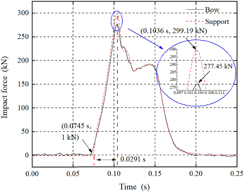
The time history curves of the impact force with GR-160 (v = 5.03 m·s−1).
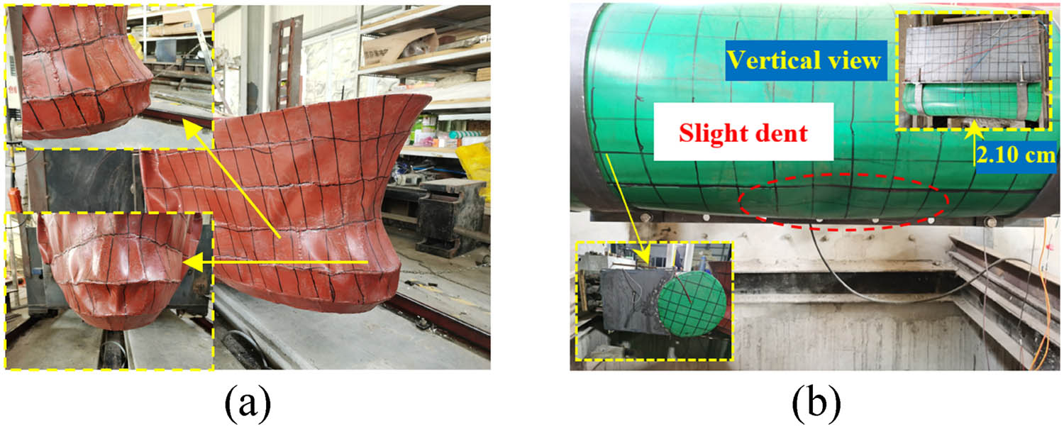
Failure modes of the bow and anti-collision facilities after the impact: (a) ship bow deformation and (b) anti-collision facilities deformation.
3.3.2.2 GR-200
Keeping the lifting height of the drop hammer unchanged and changing the web spacing of the steel box, GR-200 was tested. The actual impact speed of the cart measured was 5.07 m·s−1. The peak force of bow force sensor was 301.86 kN, and the peak force of support reaction force sensor was 328.85 kN. At the time of about 0.0729 s, the bow collides with the soft body. During the collision, the bow contacted with the soft body, the soft body had obvious deformation and rebounded rapidly, the deformation of the bow tip was more uniform, and the final crush depth was 9.32 cm. After the impact, the soft body and the steel box were not damaged obviously. The soft body was slightly dented at the median-lower part. The final distance of dent was 2.80 cm, and the deformation of the steel box was 0.10 cm. After an impact of 5.07 m·s−1, Figure 12 presents the time history curves of the impact force with GR-200. Figure 13 shows the failure modes after the impact.
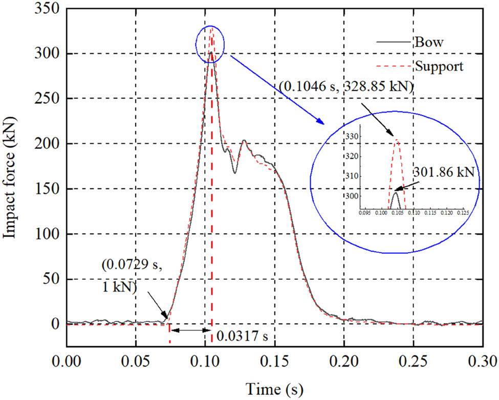
The time history curves of the impact force with GR-200 (v = 5.07 m·s−1).
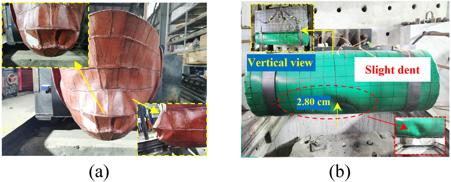
Failure modes of the bow and anti-collision facilities after the impact: (a) ship bow deformation and (b) anti-collision facilities deformation.
3.3.2.3 G-A
Keeping the lifting height of the drop hammer unchanged, G-A was tested while impacting with a steel plate. The actual impact speed of the cart measured in the test was 5.13 m·s−1. The peak force of bow force sensor was 402.52 kN, and the peak force of support reaction force sensor was 411.35 kN. There was no obvious deformation of the steel plate after the bow contacted with the steel plate during the impact, and the bow collapsed. After an impact of 5.13 m·s−1, Figure 14 presents the time history curves of the impact force with G-A. Figure 15 shows the failure modes after the impact.

The time history curves of the impact force with G-A (v = 5.13 m·s−1).
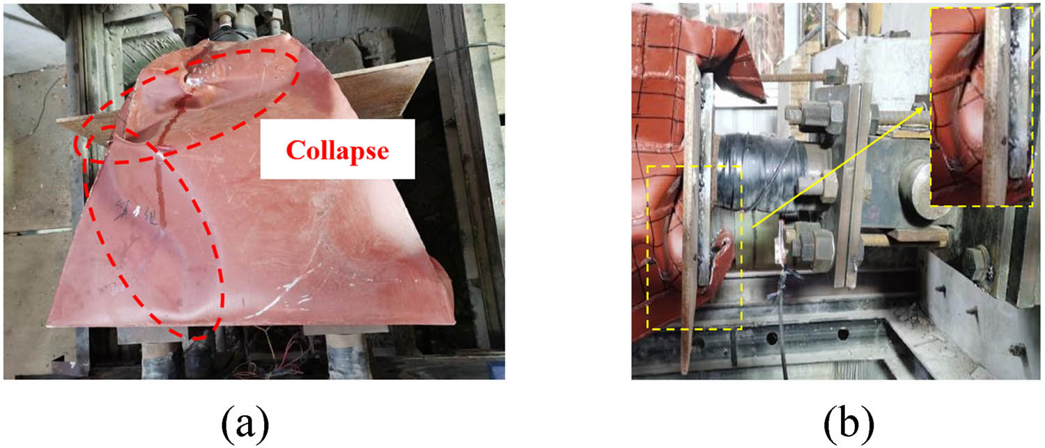
Failure modes of the bow and steel plate after the impact: (a) top view and (b) side view.
3.3.3 Analysis of experimental results
3.3.3.1 Analysis on experimental phenomena
When impacted by a ship, the impact force first diffused to the soft body cavity and was transmitted to the steel box through the internal granular filler. The flexible anti-collision facilities were greatly deformed, and the internal granular filler was restrained and squeezed to cause friction, extrusion, and crushing, for absorbing the collision energy of the ship. After the soft body cavity was compressed, it basically did not need to be repaired. It only needed to be filled with the crushed granular filler and replaced for the damaged part of the protective cover, when necessary, which shows that it has the characteristic of low maintenance rate. When the cart speed was high, the soft body and the steel box deformed obviously, indicating that the facilities can absorb energy through the deformation of steel box to resist high-energy impact.
The work mechanism of steel box-soft body combination is that this anti-collision facility has the advantages that when the pier is hit by low-energy drifters, it can rely on the soft body deformation to resist the impact. The damaged part which is the filled energy-consuming materials, can be easily replaced and supplemented, indicating that the maintenance is simple and economical with the pier and the bow effectively protected. When subjected to high-energy ship impact, the steel box takes part in deformation and energy absorption, which reduces the collision force of the ship. The proposed anti-collision facility is economic, effective, and efficient.
Under all working conditions, the deformation of the bow tip was relatively uniform. However, when G-A was tested with impacting with a steel plate, the bow collapsed, indicating that the anti-collision facilities can effectively protect the bow. The combination of steel box and soft body can not only greatly reduce the ship impact force but the bow damage as well.
3.3.3.2 Summary of impact force
The shape of the above curves show that the force increases first and then decreases with time. By comparing the three working conditions, it could be found that the time required from 1 kN to peak force was different, and G-A was the largest, which may be due to different actual impact speeds and different stiffness of the impacted specimens. According to the similarity ratio theory, the similarity ratio is 1:10 and the similarity ratio of impact force is 1:100, and the impact force obtained from the test can be used for the real model magnified according to this ratio. The test data and converted full-scale bow impact force are shown in Table 3 and Figure 16. The actual impact speeds of the cart measured in the tests may have error after lifting the drop hammer to the specified height due to the influence of factors such as friction of the steel wire rope. When the cart speed is similar, the impact peak force generated by GR-200 is higher than GR-160, but both are lower than G-A.
Summary of impact force
| Label | Impact velocity (m·s−1) | Equivalent tonnage (t) | Bow peak force (kN) | Support peak force (kN) | Actual bow peak force (MN) | Actual support peak force (MN) |
|---|---|---|---|---|---|---|
| GR-160 | 5.03 | 10,000 | 277.45 | 299.19 | 27.75 | 29.92 |
| GR-200 | 5.07 | 10,000 | 301.86 | 328.85 | 30.19 | 32.89 |
| G-A | 5.13 | 10,000 | 402.52 | 411.35 | 40.25 | 41.14 |

Comparison of bow and support impact force.
3.3.3.3 Effect of different parameters on peak force reduction rate
Table 4 summarizes the peak impact force reduction rate. Compared with the direct impact on the steel plate, GR-160 (v = 5.03 m·s−1) has the highest reduction rate of peak force under various experiments, reaching 31.07%. The impact force reduction of 160 mm web spacing (five web plates) is better than that of 200 mm (four web plates), and the maximum difference is 7.21%. It can be seen that the densified steel box web to a certain extent can improve the anti-collision performance of the whole anti-collision facilities. Compared with impacting with the steel plate under different test conditions, the peak impact force of bow has different reduction rates, indicating that the anti-collision facilities can effectively protect the bow.
Summary of peak impact force reduction rate
| Label | Reduction rate compared with the impact with steel plate (%) | |
|---|---|---|
| Bow | Support | |
| GR-160 | 31.07 | 27.27 |
| GR-200 | 25.01 | 20.06 |
3.3.3.4 Analysis on the dent distance of soft body after the impact
With the increase in impact speed, the dent distance of soft body increased, i.e., the damage of ceramsite was more serious. In addition, the difference in the compactness of ceramsite filling in the soft body will also affect the final distance of dent. Insufficient compactness will lead to more dents, resulting in the hitting between the lower part of the bow and the steel box and slightly increasing the impact force. Therefore, it fails to protect the bow but increases the bow deformation.
3.3.4 Energy absorption behavior
Figure 17 shows the energy time history curves of GR-160 and GR-200, which were obtained by integrating the load-displacement histories as shown in Figure 18. Energy absorption increases with time before reaching the peak. The peak value represents the maximum impact energy. It is known from the curves that the maximum energy absorption of GR-160 is 33,751.40 J and that of GR-200 is 34,290.34 J, but this energy is the energy absorbed by the total deformation of the bow and the anti-collision facilities. According to the load–displacement curve of the bow under the quasi-static compression test in Figure 7, when the displacement was 100 mm, i.e., when the test cart reached the maximum displacement, the energy absorption of the bow was 7,558 J. Table 5 shows the energy absorption. The bow deformation energy absorption of GR-160 accounts for 22.39%, and the anti-collision facilities deformation energy absorption accounts for 77.61%. The bow deformation energy absorption of GR-200 accounts for 22.04%, and the anti-collision facilities deformation energy absorption accounts for 77.96%. It could be concluded that the anti-collision facilities absorb most of the energy and effectively protect the bow. In addition, the total deformation energy absorption of the bow and the anti-collision facilities is less than the initial kinetic energy of the cart, which is mainly caused by the rebound speed of the impact cart, the friction energy consumption between the cart and the track, as well as the friction energy consumption of ceramsite inside the soft body. When the energy reaches the peak value, the final energy value decreases, which may be due to the elastic deformation of the soft body.
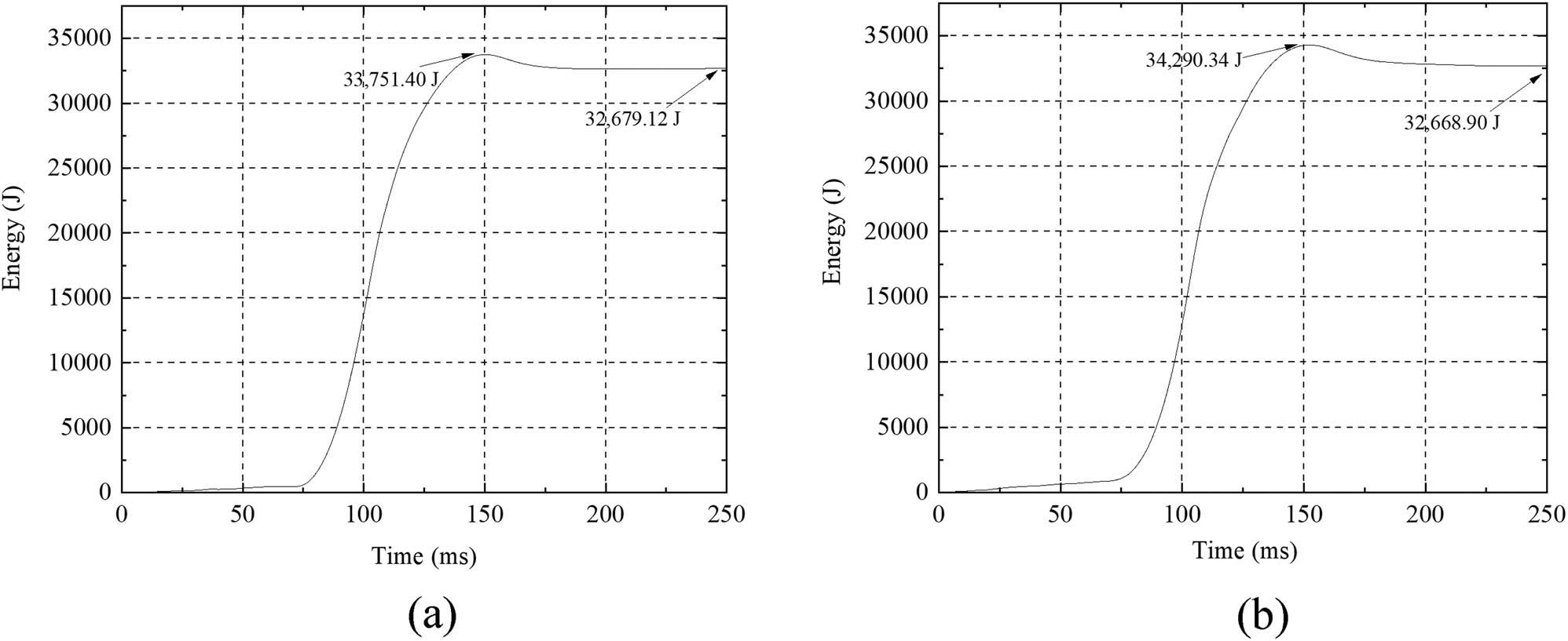
Energy–time history curves: (a) GR-160 and (b) GR-200.

Load–displacement curves of the specimens under horizontal impact test.
Summary of energy absorption
| Label | Total energy (J) | Bow energy absorption | Anti-collision facilities energy absorption | ||
|---|---|---|---|---|---|
| Value (J) | Proportion (%) | Value (J) | Proportion (%) | ||
| GR-160 | 33,751.40 | 7,558.58 | 22.39 | 26,192.82 | 77.61 |
| GR-200 | 34,290.34 | 7,558.58 | 22.04 | 26,731.76 | 77.96 |
3.3.5 Comparison of specific energy absorption (SEA) and crush load efficiency (CLE)
SEA and CLE are used as crashworthiness indexes for evaluating the crashworthiness of steel box-soft body combination. SEA represents the energy absorbed per unit mass.
where m is the sample mass, and E a is the energy absorption value of the specimens. The energy absorption value is the area enclosed by the load–displacement curve and the abscissa (displacement), the calculation formula is as follows:
where s is the compression displacement of the specimens and F(s) is the load corresponding to the compression displacement s.
The calculation formula of CLE is as follows:
where F peak represents peak crushing force. F mean is used to describe the mean energy absorption of the specimens as follows:
where E a is the energy absorption value of the specimens, and δ is the displacement.
The energy absorption can be obtained by integrating the load–displacement curve [30]. The energy results can be obtained by the area enclosed by the load–displacement curve and the abscissa under GR-160, GR-200, and G-A, which are 32,148.92, 31,713.41, and 35,106.74 J, respectively. By observing the energy–displacement curves (not given due to the length), the δ selected here is the displacement at the time of maximum energy absorption. After removing energy absorption of the bow, Table 6 lists the calculation results of crashworthiness indexes.
Calculation results of crashworthiness indexes
| Label | m (kg) | E a (J) | δ (mm) | F mean (kN) | F peak (kN) | SEA (J·kg−1) | CLE |
|---|---|---|---|---|---|---|---|
| GR-160 | 87.26 | 24,590.34 | 581.84 | 45.02 | 277.45 | 281.81 | 0.16 |
| GR-200 | 83.68 | 24,590.34 | 590.51 | 45.27 | 301.86 | 288.66 | 0.15 |
| G-A | 40.19 | 27,548.16 | 223.08 | 123.49 | 402.52 | 685.45 | 0.31 |
It can be seen from the Table 6 that the SEA values of GR-160 and GR-200 have little difference and are not high generally. This result can be explained as due to the tested specimens having heavy quality. The overall energy absorption of steel box-soft body combination is more. The SEA value of G-A is higher because the steel plate is lighter and has greater stiffness, which can withstand higher impact force. Light is not the main advantage of the proposed anti-collision facility, which is the characteristic of other designs, such as composite anti-collision facilities. Steel box-soft body combination floats up and down with the water level and can withstand high impact energy. The F peak values of GR-160 and GR-200 are low, a good anti-collision facility should have a low peak load to prevent damage to the impactor. In addition, the larger the CLE, the more serious the failure of the specimens. The CLE value of G-A is also high, which shows that the bow is seriously damaged.
4 Numerical model calibration
4.1 Simulation conditions
4.1.1 FE model of steel box-soft body combination
The simulated FE model shown in Figure 19 is consistent with the test described in the above sections and the results are processed in LS-PREPOST.

FE model (units: mm).
The Solid164 eight-node solid elements and SHELL163 four-node shell elements were utilized for modeling the steel box-soft body combination. The SHELL163 element was employed to model the steel box, protective cover, and steel plate, which was suitable for analysis of shell structure with certain thickness. The Solid164 element was used for ceramsite, which was a three-dimensional display unit with eight nodes.
Based on the tests in this work, it can be known that stress concentration will occur in the soft body part and the bow part under horizontal impact, so it is necessary to refine the mesh of these parts of the model. The anti-collision device model elements used the minimum mesh size of 20 mm. The device with four web plates consisted of 7,064 shell and 7,760 solid elements, while the device with five web plates had a little more elements. Ceramsite used the *MAT_CRUSHABLE_FOAM model, and the compressive stress–strain curve of ceramsite was input (Figure 20), which was measured by cylinder pressure test, Figure 21 shows the schematic diagram and Figure 22 illustrates the layout of the test. This model uses the *MAT_ADD_EROSION option, which is often selected to provide the erosion criteria to eliminate failed elements [31], specific failure criteria calculations can be found in ref. [32]. The soft layer employed the *MAT_ELASTIC model. The steel box used the *MAT_PLASTIC_KINEMATIC elastic-plastic material model [33]. Table 7 tabulates the specific parameter values used in the materials.
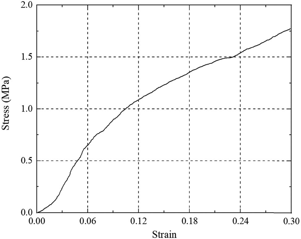
Compressive stress–strain curve of ceramsite.

Schematic diagram of pressure cylinder (units: mm).

Layout of the cylinder pressure test.
Material properties of FE model
| Material | LS-DYNA model | Input parameter | Magnitude |
|---|---|---|---|
| Ceramsite | *MAT_CRUSHABLE_FOAM | Density | 5,350 kg·m−3 |
| Elastic modulus | 12 GPa | ||
| Poisson’s ratio | 0.25 | ||
| Stress–strain curve | Measured by cylinder pressure test | ||
| Soft layer | *MAT_ELASTIC | Density | 1,350 kg·m−3 |
| Elastic modulus | 493.73 GPa | ||
| Poisson’s ratio | 0.31 | ||
| Steel bow and Steel box | *MAT_PLASTIC_KINEMATIC | Density | 7,850 kg·m−3 |
| Elastic modulus | 200 GPa | ||
| Poisson’s ratio | 0.27 | ||
| Yield stress | 310 MPa | ||
| Hardening parameter | 0 | ||
| C | 40 | ||
| P | 5 | ||
| Failure strain | 0.35 | ||
| steel block | *MAT_PLASTIC_KINEMATIC | Density | 95,000 kg·m−3 |
| Elastic modulus | 200 GPa | ||
| Poisson’s ratio | 0.27 | ||
| Yield stress | 235 MPa | ||
| Hardening parameter | 0 | ||
| C | 40 | ||
| P | 5 | ||
| Failure strain | 0.35 |
Note: C and P are the parameters of the Cowper–Symonds constitutive equation, which can be found in ref. [34].
4.1.2 FE model of impactor
The bow model used shell elements, while steel block and the hull utilized solid elements. According to the equivalent simplified model, it was consistent with the scaled bow model adopted in the test. To be similar to the actual stiffness, the bow model was carefully modeled. The decks and the outer panels were deliberately established in the model. The length, height, and width of the bow are 0.718, 0.509, and 0.78 m, respectively. The initial distance between the bow and soft body was set as 10 mm to save calculation time. The ship model was divided into bow and rear sections, as shown in Figure 19. The ship bow consisted of 9,100 shell elements, a finer mesh was adopted in the bow section than that in the rear section. Small components in the bow model were simplified [2,5]. The *MAT_ PLASTIC_KINEMATIC model was employed. The Cowper–Symonds constitutive equation was utilized to describe the elastic visco-plastic behavior of the structural steel of the ship bow. Hence, the yield stress σ y is expressed as follows:
Table 8 lists the names of indicators in equation (2). The specific parameter values can be found in ref. [34].
Contact parameters
| Symbol | Names of indicators |
|---|---|
| σ 0 | Initial yield stress |
|
|
Strain rate |
| C and P | Cowper–Symonds parameters of the strain rate |
|
|
Effective plastic strain |
|
|
Plastic hardening modulus |
|
|
Elastic modulus |
|
|
Tangent modulus |
A relatively coarse meshing was adopted to model the rear section with a total of 25,100 solid elements. The hull part was simulated by *MAT_ RIGID. It was simplified and only mass was given in the simulation because the collision mainly occurred in the bow area, with no deformations at the hull part. The actual weight of the ship was reflected by the rear section of the FE model, which was 2 m long. The specific parameter values used in the materials of other parts are tabulated in Table 7. 30 and 40 mm mesh sizes were selected to model the bow and rear part, respectively. The impact speed of the impactor was 2.26 m·s−1.
4.1.3 Contact definition
In FE simulation, contact settings between different elements are critical. This model included two contact pairs. The contact algorithm CONTACT_TIED_SHELL_EDGE_TO_SURFACE_OFFSET was defined between the soft body and the steel box contact. The dynamic and static friction coefficients were set to be 0.15. When the bow collides with the soft body, obvious deformation may occur. The contact algorithm CONTACT_AUTOMATIC_SURFACE_TO_SURFACE was defined for the bow and the anti-collision facilities contact. The specific settings of the parameters are shown in Table 9.
Contact parameters
| Contact components | Keywords | Input parameter | Magnitude |
|---|---|---|---|
| Soft body-steel box | CONTACT_TIED_SHELL_EDGE_TO_SURFACE_OFFSET | Static coefficient of friction | 0.15 |
| Scale factor of master penalty stiffness | 0.15 | ||
| Scale factor of slave penalty stiffness | 1 | ||
| Impactor-soft body | CONTACT_AUTOMATIC_SURFACE_TO_SURFACE | Static coefficient of friction | 0.15 |
| Dynamic coefficient of friction | 0.15 | ||
| Scale factor of slave penalty stiffness | 1 |
4.2 Validation and discussion
Two typical working conditions were selected, and the simulation results were analyzed. After an impact of 5.03 m·s−1, Figure 23 shows the stress distribution for the bow and the anti-collision facilities for GR-160. It can be seen that the model deformation agreed well with the test phenomenon. The bow and the anti-collision facility’s von Mises stress is shown at the fringe levels. A certain degree of deformation and stress concentration occurred in the contact part between the bow and the soft body. In addition, at the rear of the bow and the corner of the steel box, stress concentration was also observed. Figure 24 shows the comparison of the time history curves of the impact force between the numerical and experimental results when the anti-collision device model was impacted horizontally by the bow. The support peak impact force in the model test was 299.19 kN, while in the numerical simulation was 320.18 kN, the deviation was 7.01%. The impact durations of the test and the FE were about 0.10 and 0.13 s, respectively. Figure 25 presents the load–displacement curves with GR-160 between the test results and FE results. Figure 26 shows the comparison of energy–time history curves with GR-160 between the test results and FE results. The maximum absorbed energy deviation is 4.13%.
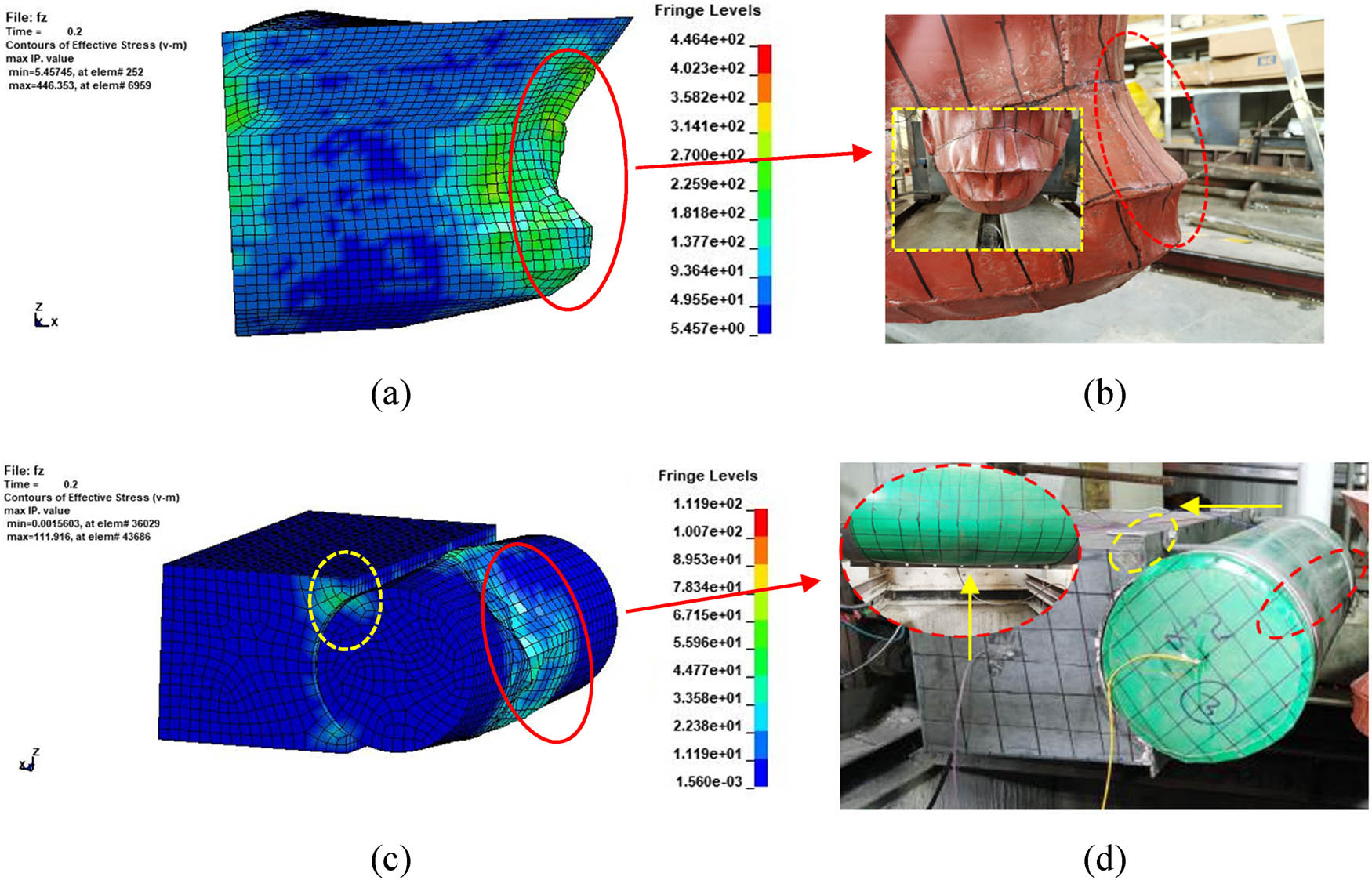
Comparison of failure modes of the ship bow and anti-collision facilities for GR-160 between FE analysis and impact test: (a) FE model of failure modes of the ship bow, (b) horizontal impact test of failure modes of the ship bow, (c) FE model of failure modes of the anti-collision facilities, and (d) horizontal impact test of failure modes of the anti-collision facilities.

Comparison of impact force with GR-160 between test results and FE results.

Load–displacement curves with GR-160 between test results and FE results.

Comparison of energy time history curves with GR-160 between test results and FE results.
After an impact of 5.13 m·s−1, Figure 27 compares the final deformation of bow and rigid body for G-A between the test and FE simulation. A large degree of deformation and stress concentration occurred at the front and rear ends of the bow. Figure 28 shows the comparison between the numerical simulation values and model test values of the bow impact on rigid body. The support peak impact force in the model test under G-A was 411.35 kN, while in the numerical simulation was 477.89 kN, the deviation was 16.18%. The impact duration was basically consistent.

Comparison between FE analysis and impact test: (a) FE model of failure modes of G-A and (b) horizontal impact test of failure modes of G-A.

Comparison of impact force with G-A between test results and FE results.
By comparing the FE models with the impact tests, it was found that the failure modes of the component were basically consistent with the tests, and the deviations of the peak force were less than 20%, which verified the applicability of the numerical simulation method used in this work. The deviation of maximum absorbed energy is small, but there is still a big difference between the two calculated energy absorption values at 200 ms (Figure 26). The deviations may come from the *MAT_CRUSHABLE_FOAM FE material model used in GR-160. When its compressive stress was too large or reached shear failure, the failure element was deleted. The steel plate and reaction wall cannot be completely fixed in G-A due to technical error and other reasons in the test. The boundary constraint on the specimen is stronger in the FE simulation, and the specimen has stronger ability to resist impact. Therefore, the peak force generated is higher (Figure 28). The existence of unloading part of the curve is due to the plastic deformation after the collision. The FE simulation of steel box-soft body combination is consistent with the time when the peak force is reached in the test. However, a gap of about 0.03 s in the impact duration was found in GR-160. This may be caused by the great contingency in the impact process. With the application of ceramsite, several gaps in the impact duration could be observed in the test. While in FE simulation, the soft body was modeled as a whole. The filling compactness of ceramsite was different between the experiment and FE simulation. Therefore, the peak value may be reached later in the FE results. In addition, the deformation of the soft body in the FE is greater, so the contact time is longer. The collision duration is also related to the mesh accuracy of the FE model. A larger mesh size will affect the rationality of the results, while a smaller mesh size will increase the calculation time and impact duration. The application of FE material parameters obtained from static test to dynamic impact may also result in different results. Finally, the complexity of the specimen structure modeling and the diversity of materials in the FE simulation will affect the impact duration.
Figure 25 shows that before reaching the peak force, the load increases linearly with the increase in displacement. After that, the curves show nonlinear behavior. At the end of the curves, the force increases slightly and several wave peaks can be observed. This observation can be explained as due to the usage of *MAT_CRUSHABLE_FOAM material model and the elements damaged by the impact will be deleted in the calculation process. When energy was dissipated to a certain extent, the overall stiffness of specimens was reduced and the phenomenon of multi peak appeared. In addition, the maximum displacement of GR-160 is 200.18 mm in the experimental observation, while in the FE results, it is 230.07 mm. The reduction in the stiffness leads to the increase in the deformation of the specimens, therefore, the peak force and maximum displacement are larger.
The initial stiffness FE value of GR-160 is slightly smaller than the test value, which may be explained by the inevitable initial defects of the specimen in the manufacturing process. For example, the thickness of fiber-reinforced rubber composites and steel plate was strictly defined in the FE method, but errors generated in the manufacturing process were inevitable in the experiment. The FE simulation was also difficult to effectively simulate the wrinkles at the interface when making the soft body cavity, as well as the connection mode between steel box and soft body. In the test, the steel box and the soft body were connected by bolts, while in the simulation, they were bound by ties. Finally, the boundary constraints of the specimen were also different, the constraints were more fixed in the FE method.
Generally, the response of specimens can be effectively simulated. The appropriate material model, boundary conditions, and contact algorithm can effectively simulate the response of the anti-collision facilities. The model parameters selected in this work can be referred for further simulation.
5 Conclusion
Considering the disadvantages of separate application of rigid and flexible anti-collision facilities, this work proposed a combination of the above two facilities and investigated its performance. The main conclusions are listed as follows:
Compared with the direct impact on the steel plate, GR-160 (v = 5.03 m·s−1) has the highest reduction rate of peak force under various experiments, reaching 31.07%. The densified steel box web can improve the anti-collision performance of the whole anti-collision facilities. The peak impact force of bow has different reduction rates, indicating that the anti-collision facilities can protect the bow effectively.
By analyzing energy absorption behavior, the anti-collision facilities deformation energy absorption of GR-160 and GR-200 accounts for 77.61 and 77.96%, respectively. It can be observed that the anti-collision facilities absorb most of the energy and protect the bow.
Based on ANSYS/LS-DYNA dynamic FE software, the numerical simulation was conducted for duplicating the experiment. The response of specimens can be effectively simulated. The FE analysis results are coincident with the model impact test results. The applicability of the FE method used in this work can provide reference for more simulations.
Acknowledgments
The research described herein was supported by the Natural Science Foundation for distinguished Young Scholars of Jiangsu Province (Grant No. BK20190034), and the National Natural Science Foundation of China (Grant No. 52078248).
-
Funding information: The research described herein was supported by the Natural Science Foundation for the National Natural Science Foundation of China (Grant No. 52078248).
-
Author contributions: Y.H.F. proposed the concept and research method of steel box-soft body combination anti-collision facility, used ANSYS/LS-DYNA to conduct the numerical simulation and wrote the manuscript. F.H. explained the professional terms and participated in the discussion of research methods. Z.L. analyzed the anti-collision facility and conducted the numerical simulation. J.E.S. participated in the discussion of the research methods. D.Z.W. verified and studied the model through experiments. Z.X.C. revised and edited the manuscript. All authors have accepted responsibility for the entire content of this manuscript and approved its submission.
-
Conflict of interest: The authors state no conflict of interest.
-
Data availability statement: The datasets generated during and/or analyzed during the current study are available from the corresponding author on reasonable request.
References
[1] Perera, L. P. and C. G. Soares. Collision risk detection and quantification in ship navigation with integrated bridge systems. Ocean Engineering, Vol. 109, No. 15, 2015, pp. 344–354.10.1016/j.oceaneng.2015.08.016Suche in Google Scholar
[2] Fang, H., Y. Mao, W. Liu, L. Zhu, and B. Zhang. Manufacturing and evaluation of large-scale composite bumper system for bridge pier protection against ship collision. Composite Structures, Vol. 158, 2016, pp. 187–198.10.1016/j.compstruct.2016.09.013Suche in Google Scholar
[3] Zhu, L., W. Liu, H. Fang, J. Chen, Y. Zhuang, and J. Han. Design and simulation of innovative foam-filled lattice composite bumper system for bridge protection in ship collisions. Composites Part B: Engineering, Vol. 157, 2019, pp. 24–35.10.1016/j.compositesb.2018.08.067Suche in Google Scholar
[4] Wang, J. J., Y. C. Song, W. Wang, and L. F. Tu. Evaluation of composite crashworthy device for pier protection against barge impact. Ocean Engineering, Vol. 169, 2018, pp. 144–158.10.1016/j.oceaneng.2018.09.026Suche in Google Scholar
[5] Jiang, H. and M. G. Chorzepa. Evaluation of a floating steel fender system for bridge pier protection against vessel collision. Journal of Bridge Engineering, Vol. 21, No. 11, 2016, id. 05016008.10.1061/(ASCE)BE.1943-5592.0000947Suche in Google Scholar
[6] Wang, W., G. Morgenthal, and M. Kraus. Numerical evaluation of a novel crashworthy device for pier protection from barge impact. Engineering Structures, Vol. 212, 2020, id. 110535.10.1016/j.engstruct.2020.110535Suche in Google Scholar
[7] Wang, J. J., Y. C. Song, W. Wang, and C. J. Chen. Evaluation of flexible floating anti-collision device subjected to ship impact using finite-element method. Ocean Engineering, Vol. 178, 2019, pp. 321–330.10.1016/j.oceaneng.2019.03.005Suche in Google Scholar
[8] Zhou, L., H. Li, J. Wei, X. Pu, A. D. Mahunon, and L. Jiang. Design and simulation analysis of a new type of assembled UHPC collision avoidance. Applied Sciences, Vol. 10, No. 13, 2020, id. 4555.10.3390/app10134555Suche in Google Scholar
[9] Chen, W., Y. G. Wang, W. W. Li, L. M. Yang, J. Liu, X. L. Dong, et al. An adaptive arresting vessel device for protecting bridges over non-navigable water against vessel collision. Engineering Structures, Vol. 237, 2021, id. 112145.10.1016/j.engstruct.2021.112145Suche in Google Scholar
[10] Shan, C. Analysis of collision performance of anticollision box made of steel-polyurethane sandwich plates. Journal of Constructional Steel Research, Vol. 175, No. 1, 2020, id. 106357.10.1016/j.jcsr.2020.106357Suche in Google Scholar
[11] Gunasekaran, M. and M. P. Salaimanimagudam. A novel steel-PAFRC composite fender for bridge pier protection under low velocity vessel impacts. Structures, Vol. 26, 2020, pp. 765–777.10.1016/j.istruc.2020.05.005Suche in Google Scholar
[12] Fan, W., W. Guo, Y. Sun, B. Chen, and X. Shao. Experimental and numerical investigations of a novel steel-UHPFRC composite fender for bridge protection in vessel collisions. Ocean Engineering, Vol. 165, 2018, pp. 1–21.10.1016/j.oceaneng.2018.07.028Suche in Google Scholar
[13] Wang, J. J., Y. C. Song, W. Wang, and J. Li. Calibrations of numerical models by experimental impact tests using scaled steel boxes. Engineering Structures, Vol. 173, 2018, pp. 481–494.10.1016/j.engstruct.2018.06.100Suche in Google Scholar
[14] Xie, H., H. Fang, W. Cai, L. Wan, R. Huo, and D. Hui. Development of an innovative composite sandwich matting with GFRP facesheets and wood core. Reviews on Advanced Materials Science, Vol. 60, No. 1, 2021, pp. 80–91.10.1515/rams-2021-0016Suche in Google Scholar
[15] Kameshwar, S. and J. E. Padgett. Response and fragility assessment of bridge columns subjected to barge-bridge collision and scour. Engineering Structures, Vol. 168, 2018, pp. 308–319.10.1016/j.engstruct.2018.04.082Suche in Google Scholar
[16] Fan, W., Z. Zhong, X. Huang, W. Sun, and W. Mao. Multi-platform simulation of reinforced concrete structures under impact loading. Engineering Structures, Vol. 266, 2022, id. 114523.10.1016/j.engstruct.2022.114523Suche in Google Scholar
[17] Fan, W., Z. Zhang, X. Huang, and W. Sun. A simplified method to efficiently design steel fenders subjected to vessel head-on collisions. Marine Structures, Vol. 74, 2020, id. 102840.10.1016/j.marstruc.2020.102840Suche in Google Scholar
[18] Niknejad, A., S. A. Elahi, and G. H. Liaghat. Experimental investigation on the lateral compression in the foam-filled circular tubes. Materials & Design, Vol. 36, 2012, pp. 24–34.10.1016/j.matdes.2011.10.047Suche in Google Scholar
[19] Niknejad, A., H. Assaee, S. A. Elahi, and A. Golriz. Flattening process of empty and polyurethane foam-filled E-glass/vinylester composite tubes - An experimental study. Composite Structures, Vol. 100, 2013, pp. 479–492.10.1016/j.compstruct.2013.01.009Suche in Google Scholar
[20] Liu, Z. F., Z. C. Huang, and Q. H. Qin. Experimental and theoretical investigations on lateral crushing of aluminum foam-filled circular tubes. Composite Structures, Vol. 175, 2017, pp. 19–27.10.1016/j.compstruct.2017.05.004Suche in Google Scholar
[21] Ujihashi, S., T. Yamanaka, H. Kuroda, and N. Inou. Energy-absorption abilities of CFRP cylinders during impact crushing. Thin-Walled Structures, Vol. 28, No. 3, 1997, pp. 297–307.10.1016/S0263-8231(97)00048-7Suche in Google Scholar
[22] AASHTO, editor., Guide specification and commentary for vessel collision design of highway bridges. American Association of State Highway and Transportation Officials, Washington, DC, 2009.Suche in Google Scholar
[23] Fan, W., W. Yuan, and B. Chen. Steel fender limitations and improvements for bridge protection in ship collisions. Journal of Bridge Engineering, Vol. 20, No. 12, 2015, pp. 1–9.10.1061/(ASCE)BE.1943-5592.0000785Suche in Google Scholar
[24] Huang, C., L. Cui, H. Xia, Y. Qiu, and Q. Q. Ni. A numerical study on the low-velocity impact behavior of the Twaron(R) fabric subjected to oblique impact. Reviews on Advanced Materials Science, Vol. 60, No. 1, 2021, pp. 980–994.10.1515/rams-2021-0077Suche in Google Scholar
[25] Luo, Y., K. Yuan, L. Shen, and J. Liu. Sandwich panel with in-plane honeycombs in different Poisson’s ratio under low to medium impact loads. Reviews on Advanced Materials Science, Vol. 60, No. 1, 2021, pp. 145–157.10.1515/rams-2021-0020Suche in Google Scholar
[26] Zhang, X. Y., C. Xia, and Y. Chen. Research on nano-concrete-filled steel tubular columns with end plates after lateral impact. Reviews on Advanced Materials Science, Vol. 60, No. 1, 2021, pp. 553–566.10.1515/rams-2021-0044Suche in Google Scholar
[27] Hong, J., S. Zhang, H. Fang, X. Xu, H. Xie, and Y. Wang. Structural performance of textile reinforced concrete sandwich panels under axial and transverse load. Reviews on Advanced Materials Science, Vol. 60, No. 1, 2021, pp. 64–79.10.1515/rams-2021-0015Suche in Google Scholar
[28] Wu, Z., W. Liu, L. Wang, H. Fang, and D. Hui. Theoretical and experimental study of foam-filled lattice composite panels under quasi-static compression loading. Composites Part B, Vol. 60, 2014, pp. 329–340.10.1016/j.compositesb.2013.12.078Suche in Google Scholar
[29] Ahmadi, S. A., M. H. Pashaei, and R. A. Jafari-Talookolaei. Three-dimensional elastic-plastic pulse response and energy absorption of curved composite sandwich panel using DQ – Newmark method. Engineering Structures, Vol. 189, 2019, pp. 111–128.10.1016/j.engstruct.2019.03.041Suche in Google Scholar
[30] Taraghi, I. and A. Fereidoon. Non-destructive evaluation of damage modes in nanocomposite foam-core sandwich panel subjected to low-velocity impact. Composites Part B: Engineering, Vol. 103, 2016, pp. 51–59.10.1016/j.compositesb.2016.08.009Suche in Google Scholar
[31] Jiang, H. and M. G. Chorzepa. Evaluation of a new FRP fender system for bridge pier protection against vessel collision. Journal of Bridge Engineering, Vol. 20, No. 2, 2015, id. 05014010.10.1061/(ASCE)BE.1943-5592.0000658Suche in Google Scholar
[32] Chen, J., L. Zhu, H. Fang, J. Han, R. Huo, and P. Wu. Study on the low-velocity impact response of foam-filled multi-cavity composite panels. Thin-Walled Structures, Vol. 173, 2022, id. 108953.10.1016/j.tws.2022.108953Suche in Google Scholar
[33] Livermore Software Technology (LSTC). LS-DYNA keyword user’s manual, version 971[R], Livermore (CA); 2010.Suche in Google Scholar
[34] Wan, Y. L., L. Zhu, H. Fang, W. Liu, and Y. Mao. Experimental testing and numerical simulations of ship impact on axially loaded reinforced concrete piers. International Journal of Impact Engineering, Vol. 125, 2018, pp. 246–262.10.1016/j.ijimpeng.2018.11.016Suche in Google Scholar
© 2023 the author(s), published by De Gruyter
This work is licensed under the Creative Commons Attribution 4.0 International License.
Artikel in diesem Heft
- Review Articles
- Progress in preparation and ablation resistance of ultra-high-temperature ceramics modified C/C composites for extreme environment
- Solar lighting systems applied in photocatalysis to treat pollutants – A review
- Technological advances in three-dimensional skin tissue engineering
- Hybrid magnesium matrix composites: A review of reinforcement philosophies, mechanical and tribological characteristics
- Application prospect of calcium peroxide nanoparticles in biomedical field
- Research progress on basalt fiber-based functionalized composites
- Evaluation of the properties and applications of FRP bars and anchors: A review
- A critical review on mechanical, durability, and microstructural properties of industrial by-product-based geopolymer composites
- Multifunctional engineered cementitious composites modified with nanomaterials and their applications: An overview
- Role of bioglass derivatives in tissue regeneration and repair: A review
- Research progress on properties of cement-based composites incorporating graphene oxide
- Properties of ultra-high performance concrete and conventional concrete with coal bottom ash as aggregate replacement and nanoadditives: A review
- A scientometric review of the literature on the incorporation of steel fibers in ultra-high-performance concrete with research mapping knowledge
- Weldability of high nitrogen steels: A review
- Application of waste recycle tire steel fibers as a construction material in concrete
- Wear properties of graphene-reinforced aluminium metal matrix composite: A review
- Experimental investigations of electrodeposited Zn–Ni, Zn–Co, and Ni–Cr–Co–based novel coatings on AA7075 substrate to ameliorate the mechanical, abrasion, morphological, and corrosion properties for automotive applications
- Research evolution on self-healing asphalt: A scientometric review for knowledge mapping
- Recent developments in the mechanical properties of hybrid fiber metal laminates in the automotive industry: A review
- A review of microscopic characterization and related properties of fiber-incorporated cement-based materials
- Comparison and review of classical and machine learning-based constitutive models for polymers used in aeronautical thermoplastic composites
- Gold nanoparticle-based strategies against SARS-CoV-2: A review
- Poly-ferric sulphate as superior coagulant: A review on preparation methods and properties
- A review on ceramic waste-based concrete: A step toward sustainable concrete
- Modification of the structure and properties of oxide layers on aluminium alloys: A review
- A review of magnetically driven swimming microrobots: Material selection, structure design, control method, and applications
- Polyimide–nickel nanocomposites fabrication, properties, and applications: A review
- Design and analysis of timber-concrete-based civil structures and its applications: A brief review
- Effect of fiber treatment on physical and mechanical properties of natural fiber-reinforced composites: A review
- Blending and functionalisation modification of 3D printed polylactic acid for fused deposition modeling
- A critical review on functionally graded ceramic materials for cutting tools: Current trends and future prospects
- Heme iron as potential iron fortifier for food application – characterization by material techniques
- An overview of the research trends on fiber-reinforced shotcrete for construction applications
- High-entropy alloys: A review of their performance as promising materials for hydrogen and molten salt storage
- Effect of the axial compression ratio on the seismic behavior of resilient concrete walls with concealed column stirrups
- Research Articles
- Effect of fiber orientation and elevated temperature on the mechanical properties of unidirectional continuous kenaf reinforced PLA composites
- Optimizing the ECAP processing parameters of pure Cu through experimental, finite element, and response surface approaches
- Study on the solidification property and mechanism of soft soil based on the industrial waste residue
- Preparation and photocatalytic degradation of Sulfamethoxazole by g-C3N4 nano composite samples
- Impact of thermal modification on color and chemical changes of African padauk, merbau, mahogany, and iroko wood species
- The evaluation of the mechanical properties of glass, kenaf, and honeycomb fiber-reinforced composite
- Evaluation of a novel steel box-soft body combination for bridge protection against ship collision
- Study on the uniaxial compression constitutive relationship of modified yellow mud from minority dwelling in western Sichuan, China
- Ultrasonic longitudinal torsion-assisted biotic bone drilling: An experimental study
- Green synthesis, characterizations, and antibacterial activity of silver nanoparticles from Themeda quadrivalvis, in conjugation with macrolide antibiotics against respiratory pathogens
- Performance analysis of WEDM during the machining of Inconel 690 miniature gear using RSM and ANN modeling approaches
- Biosynthesis of Ag/bentonite, ZnO/bentonite, and Ag/ZnO/bentonite nanocomposites by aqueous leaf extract of Hagenia abyssinica for antibacterial activities
- Eco-friendly MoS2/waste coconut oil nanofluid for machining of magnesium implants
- Silica and kaolin reinforced aluminum matrix composite for heat storage
- Optimal design of glazed hollow bead thermal insulation mortar containing fly ash and slag based on response surface methodology
- Hemp seed oil nanoemulsion with Sapindus saponins as a potential carrier for iron supplement and vitamin D
- A numerical study on thin film flow and heat transfer enhancement for copper nanoparticles dispersed in ethylene glycol
- Research on complex multimodal vibration characteristics of offshore platform
- Applicability of fractal models for characterising pore structure of hybrid basalt–polypropylene fibre-reinforced concrete
- Influence of sodium silicate to precursor ratio on mechanical properties and durability of the metakaolin/fly ash alkali-activated sustainable mortar using manufactured sand
- An experimental study of bending resistance of multi-size PFRC beams
- Characterization, biocompatibility, and optimization of electrospun SF/PCL composite nanofiber films
- Morphological classification method and data-driven estimation of the joint roughness coefficient by consideration of two-order asperity
- Prediction and simulation of mechanical properties of borophene-reinforced epoxy nanocomposites using molecular dynamics and FEA
- Nanoemulsions of essential oils stabilized with saponins exhibiting antibacterial and antioxidative properties
- Fabrication and performance analysis of sustainable municipal solid waste incineration fly ash alkali-activated acoustic barriers
- Electrostatic-spinning construction of HCNTs@Ti3C2T x MXenes hybrid aerogel microspheres for tunable microwave absorption
- Investigation of the mechanical properties, surface quality, and energy efficiency of a fused filament fabrication for PA6
- Experimental study on mechanical properties of coal gangue base geopolymer recycled aggregate concrete reinforced by steel fiber and nano-Al2O3
- Hybrid bio-fiber/bio-ceramic composite materials: Mechanical performance, thermal stability, and morphological analysis
- Experimental study on recycled steel fiber-reinforced concrete under repeated impact
- Effect of rare earth Nd on the microstructural transformation and mechanical properties of 7xxx series aluminum alloys
- Color match evaluation using instrumental method for three single-shade resin composites before and after in-office bleaching
- Exploring temperature-resilient recycled aggregate concrete with waste rubber: An experimental and multi-objective optimization analysis
- Study on aging mechanism of SBS/SBR compound-modified asphalt based on molecular dynamics
- Evolution of the pore structure of pumice aggregate concrete and the effect on compressive strength
- Effect of alkaline treatment time of fibers and microcrystalline cellulose addition on mechanical properties of unsaturated polyester composites reinforced by cantala fibers
- Optimization of eggshell particles to produce eco-friendly green fillers with bamboo reinforcement in organic friction materials
- An effective approach to improve microstructure and tribological properties of cold sprayed Al alloys
- Luminescence and temperature-sensing properties of Li+, Na+, or K+, Tm3+, and Yb3+ co-doped Bi2WO6 phosphors
- Effect of molybdenum tailings aggregate on mechanical properties of engineered cementitious composites and stirrup-confined ECC stub columns
- Experimental study on the seismic performance of short shear walls comprising cold-formed steel and high-strength reinforced concrete with concealed bracing
- Failure criteria and microstructure evolution mechanism of the alkali–silica reaction of concrete
- Mechanical, fracture-deformation, and tribology behavior of fillers-reinforced sisal fiber composites for lightweight automotive applications
- UV aging behavior evolution characterization of HALS-modified asphalt based on micro-morphological features
- Preparation of VO2/graphene/SiC film by water vapor oxidation
- A semi-empirical model for predicting carbonation depth of RAC under two-dimensional conditions
- Comparison of the physical properties of different polyimide nanocomposite films containing organoclays varying in alkyl chain lengths
- Effects of freeze–thaw cycles on micro and meso-structural characteristics and mechanical properties of porous asphalt mixtures
- Flexural performance of a new type of slightly curved arc HRB400 steel bars reinforced one-way concrete slabs
- Alkali-activated binder based on red mud with class F fly ash and ground granulated blast-furnace slag under ambient temperature
- Facile synthesis of g-C3N4 nanosheets for effective degradation of organic pollutants via ball milling
- DEM study on the loading rate effect of marble under different confining pressures
- Conductive and self-cleaning composite membranes from corn husk nanofiber embedded with inorganic fillers (TiO2, CaO, and eggshell) by sol–gel and casting processes for smart membrane applications
- Laser re-melting of modified multimodal Cr3C2–NiCr coatings by HVOF: Effect on the microstructure and anticorrosion properties
- Damage constitutive model of jointed rock mass considering structural features and load effect
- Thermosetting polymer composites: Manufacturing and properties study
- CSG compressive strength prediction based on LSTM and interpretable machine learning
- Axial compression behavior and stress–strain relationship of slurry-wrapping treatment recycled aggregate concrete-filled steel tube short columns
- Space-time evolution characteristics of loaded gas-bearing coal fractures based on industrial μCT
- Dual-biprism-based single-camera high-speed 3D-digital image correlation for deformation measurement on sandwich structures under low velocity impact
- Effects of cold deformation modes on microstructure uniformity and mechanical properties of large 2219 Al–Cu alloy rings
- Basalt fiber as natural reinforcement to improve the performance of ecological grouting slurry for the conservation of earthen sites
- Interaction of micro-fluid structure in a pressure-driven duct flow with a nearby placed current-carrying wire: A numerical investigation
- A simulation modeling methodology considering random multiple shots for shot peening process
- Optimization and characterization of composite modified asphalt with pyrolytic carbon black and chicken feather fiber
- Synthesis, characterization, and application of the novel nanomagnet adsorbent for the removal of Cr(vi) ions
- Multi-perspective structural integrity-based computational investigations on airframe of Gyrodyne-configured multi-rotor UAV through coupled CFD and FEA approaches for various lightweight sandwich composites and alloys
- Influence of PVA fibers on the durability of cementitious composites under the wet–heat–salt coupling environment
- Compressive behavior of BFRP-confined ceramsite concrete: An experimental study and stress–strain model
- Interval models for uncertainty analysis and degradation prediction of the mechanical properties of rubber
- Preparation of PVDF-HFP/CB/Ni nanocomposite films for piezoelectric energy harvesting
- Frost resistance and life prediction of recycled brick aggregate concrete with waste polypropylene fiber
- Synthetic leathers as a possible source of chemicals and odorous substances in indoor environment
- Mechanical properties of seawater volcanic scoria aggregate concrete-filled circular GFRP and stainless steel tubes under axial compression
- Effect of curved anchor impellers on power consumption and hydrodynamic parameters of yield stress fluids (Bingham–Papanastasiou model) in stirred tanks
- All-dielectric tunable zero-refractive index metamaterials based on phase change materials
- Influence of ultrasonication time on the various properties of alkaline-treated mango seed waste filler reinforced PVA biocomposite
- Research on key casting process of high-grade CNC machine tool bed nodular cast iron
- Latest research progress of SiCp/Al composite for electronic packaging
- Special Issue on 3D and 4D Printing of Advanced Functional Materials - Part I
- Molecular dynamics simulation on electrohydrodynamic atomization: Stable dripping mode by pre-load voltage
- Research progress of metal-based additive manufacturing in medical implants