Exergy analysis of a conceptual CO2 capture process with an amine-based DES
-
 ,
,

Abstract
The energy efficiency of an absorption–desorption system for carbon dioxide capture from flue gas utilizing methyltriphenylphosphonium bromide-monoethanolamine (MEA) deep eutectic solvent is investigated in this article. According to the results, when the working pressure of the absorber column increases, the process becomes significantly exergy deficient, with an exergy loss of 7.63 MW compared to 5.7 MW for a normal MEA process. The majority of the exergy deficit is due to flue gas compression effort, which accounts for 99% of the total process exergy. The process’s exergy shortfall can be improved by lowering the absorber pressure from 10 to 3 atm, lowering the carbon dioxide removal efficiency from 90% to 60%, and increasing the solvent-to-gas ratio from 075 to 7.05. Furthermore, the incorporation of an energy recovery device could allow for an 80–90% reduction in the energy consumed by the gas compressor when running at 10 atm, from 5.7 to 1.2 MJ‧kg CO2 −1. With this adjustment, the deep eutectic solvent-based process can match or outperform the corresponding aqueous alkanolamine solvent-based process in terms of exergy destruction and specific energy consumption.
Abbreviations
- C p
-
heat capacity (kJ‧kg−1‧K−1)
- E
-
exergy (kJ‧kg−1)
- G
-
sour gas flow rate (kmol‧h−1)
- H,H 0
-
enthalpy and reference enthalpy (kJ‧kg−1)
- L
-
solvent circulation rate (kmol‧h−1)
- m
-
mass flow rate (kg‧s−1)
- M w
-
molecular weight (g‧mol−1)
- mHE2
-
heating fluid flow rate in heat exchanger 2 (kg‧kg CO2 −1)
- mHE3
-
cooling fluid flow rate in heat exchanger 3 (kg‧kg CO2 −1)
- mHE4
-
cooling fluid flow rate in heat exchanger 4 (kg‧kg CO2 −1)
- mCon
-
coolant flow rate in stripper condenser (kg‧kg CO2 −1)
- mReS
-
steam flow rate in reboiler (kg‧kg CO2 −1)
- P
-
pressure (atm)
- P 0
-
reference pressure (atm)
- P r
-
reduced pressure
- P a
-
absorber pressure (atm)
- Q
-
heat load (kJ‧s−1)
- R
-
ideal gas constant
- S, S 0
-
entropy, reference entropy (kJ‧kg−1‧K−1)
- T 0
-
reference temperature (K)
- T
-
temperature (K)
- T a
-
absorber temperature (K)
- T c
-
critical temperature (K)
- T n
-
normal boiling temperature (K)
- T r
-
reduced temperature
- T s
-
stripper temperature for DES process (K)
- THE2i, THE2
-
inlet, outlet temperature of heating fluid in HE2 (K)
- THE3i, THE3
-
inlet, outlet temperature of heating fluid in HE3 (K)
- THE4i, THE4
-
inlet, outlet temperature of heating fluid in HE4 (K)
- T st
-
stripper top temperature (K)
- T sd
-
stripper distillate temperature (K)
- T re
-
stripper reboiler temperature (K)
- T si
-
stripper inlet temperature (K)
- T sb
-
stripper bottom temperature (K)
- W
-
work (kJ‧s−1)
- x f, x o
-
CO2 mole fraction in a lean and rich solvent, respectively
Greek letter
- ω
-
the acentric factor
- η p
-
pump efficiency
- η c
-
compressor efficiency
- γ
-
the heat capacity ratio
Subscript
- i, in
-
input
- o, out
-
output
- 0
-
reference
Superscript
- L
-
liquid
- R
-
residual
- V
-
vapor
1 Introduction
Globally, energy-intensive activities are the primary sources of anthropogenic carbon dioxide (CO2) emissions, with fossil fuel combustion in transportation, power production, and industry accounting for around 90% of total emissions [1]. After 3 years of stagnant or little global emissions between 2014 and 2016 [2,3], CO2 emissions rose by 1.6% in 2017 to 36.2 Gt (billion tons) and grew a further 2.7% in 2018 (range: 1.8–3.7%) to a record of 37.1 ± 2 Gt CO2 [4]. According to the International Energy Agency (IEA), due to the increasing energy demand, global CO2 emissions from the energy-producing sector increased by 1.7% in 2018, reaching a historic high of 33.1 Gt CO2, the fastest pace of rise since 2013. Although the emissions from all fossil fuels increased, the power sector alone contributed nearly two-thirds of the emissions growth. Specifically, coal-based power plants alone accounted for more than 10 Gt CO2. CO2 is the primary contributor to global warming impacts along with other greenhouse gases [5,6]. CO2 capture and storage (CCS) technologies could be a potential solution to mitigate the emission of CO2 into the atmosphere by up to 20%. However, the debate regarding CCS becomes intense regarding the cost of energy production because it increases by approximately 30–80% when CCS is applied [6,7]. Therefore, for cleaner energy production, it is important to use cost-effective technology.
The conventional CCS approach is CO2 absorption using liquid absorbents and is considered the most mature, practically operational, and successfully demonstrated technology [8,9]. Considering the techno-economic aspect of the CO2 chemisorption process, the selection of solvents is decisive. Solvents with fast kinetics of CO2 absorption, high CO2 capture capacity, low vapor pressure, and high stability against thermal and oxidative degradation should be ideal for CO2 capture [10]. Among the liquid solvents, the aqueous alkanolamine solutions such as monoethanolamine (MEA), diethanolamine (DEA), methyl diethanolamine (MDEA), triethanolamine, 2-amino-2-methyl-1-propanol (AMP), and 2-methylaminoethanol were the most commonly used solvents over the last 60 years [11,12]. New amine-based solvents such as dimethylamino-2-methyl-1-propanol [13] and aqueous blends of conventional amines [14] were tested as well. The aqueous blends of MEA, MDEA, and AMP investigated by Chen et al. [14] resulted in a desorption rate up to five times higher than the commercial aqueous 5 M MEA solution, combined with a significantly lower relative heat duty for regeneration and lower operating cost. However, despite the high affinity of amine solvents for CO2 molecules, some serious technological drawbacks exist when using the conventional aqueous amine scrubbing process. Specifically, the high-energy requirement for absorbent regeneration and the significant equipment corrosion that occurs makes the process challenging and expensive because of the high-temperature difference between CO2 absorption (50°C) and desorption (120–140°C) units. Therefore, a high amount of energy is required to maintain the thermal difference in this system.
Currently, the critical limitation preventing the implementation of large-scale CCS globally on the major sources of CO2 emissions is approximately 3.2–4.0 GJ‧ton CO2 −1. Through extensive fundamental studies and several industrial demonstrations (e.g., Boundary Dam, Canada, and Petra Nova, USA) [15], using amine-based technologies achieved a great reduction in energy requirements, with 2.3–2.4 GJ‧ton CO2 −1 removed compared with 3.5 GJ‧ton CO2 −1 removed with first-generation amine scrubbing [16]. However, the current energy penalty level of CO2 chemisorption is still unbearable if a full-scale CO2 removal process is to be implemented for a coal-fired power plant. Researchers focus on exploring refined techniques or finding new and more efficient amine solutions that could reduce the energy penalty during the regeneration part of the process [17,18,19]. It has been reported that water might not be the optimal solvent to use due to high heat capacity, the heat of vaporization, and vapor pressure [20], inclusive of high-energy requirements during the regeneration process [21]. Furthermore, the detrimental ability of water to induce the degradation/corrosion of the amine and process equipment is also a concern [22].
Nonaqueous solutions were proposed as possible alternatives, replacing water with room-temperature ionic liquids (ILs), CO2-binding liquids, or organic solvents such as methanol or ethanol to reduce the energy penalty during the regeneration step [23,24,25,26,27]. The emergence of binary or ternary blended solvents of amines [28,29] or amines with organics [30], such as alcohols, ethers, and glycols, allowed for the design of advanced nonaqueous absorbents. Because of their lower specific heat than water and low desorption temperature, organic solvents could provide significant advantages for saving the regeneration energy and reducing corrosiveness and degradation. In a nonaqueous process using MEA/methanol as an absorbent, the removal of methanol below 373 K for solvent regeneration resulted in enormous energy savings [31]. A mixture of a nonaqueous absorbent of piperazine (PZ) with diethylene glycol to capture CO2 in a rotating packed bed has been proposed elsewhere [32]. The results showed that using glycols as solvents significantly reduced energy consumption with almost negligible solvent evaporation and avoidance of thermal degradation. Another study demonstrated secondary alkanolamines/EG as cost-effective absorbents for rapid and reversible CO2 capture [33]. Chen et al. studied the solubility of CO2 in N-ethylmonoethanolamine solutions using the vapor–liquid equilibrium (VLE) and the absorption–desorption apparatus. Their results showed that the tertiary amine, N,N-diethylethanolamine, used as a nonaqueous solvent demonstrated more excellent performance than alcohols and glycols [34]. Recently, nonaqueous binary absorbents of conventional amines (MEA and MDEA) with low-viscosity ILs were investigated for CO2 capture. The mixed absorbent MDEA + [BEIM]BF4 with low viscosity demonstrated a high recycling CO2 capacity, energy-saving capacity, and good renewability [35]. The absorption–desorption performance of CO2 into several blends of MEA or DEA with glycol ethers (2-methoxy ethanol (2ME) and 2-ethoxy ethanol (2EE)) as nonaqueous solvents has been reported at ambient pressure. It was found that the mixture of MEA and 2ME or 2EE demonstrated a significant reduction in energy consumption (55%) compared with the benchmark aqueous 5.0 M MEA system.
ILs and deep eutectic solvents (DESs) are among the most attractive substitutes that have been examined over the past few years because of their favorable properties. These properties include negligible vapor pressure, high thermal stability, nonflammability, and tuneability for the desired separation process by changing the combination of cations and anions [36]. For CO2 capture, various ILs containing amine-functionalized cations/anions [35,37], amino acids [38], aprotic heterocyclic anions, super bases [39], and pyridinium anions [40] have been investigated. Nevertheless, the main problems associated with ILs regarding their application for CO2 capture are their high susceptibility to contamination, poor biodegradability, high toxicity [8], increasing viscosity during CO2 capture, and high cost for large-scale industrial application [41].
To overcome the problems associated with ILs while retaining their advantages, DESs appeared as a credible alternative [42,43]. DESs are sustainable solvents analogous to ILs but with several advantages over ILs such as biodegradability, high thermal and chemical stabilities, nonflammability, a wide liquid range, and high purity. Furthermore, DESs are less expensive and easier to synthesize by combining an organic halide salt (considered the hydrogen bond acceptor) with another hydrogen bond donor, such as an amine, amide, carboxylic acid, and alcohol in a certain ratio, resulting in the formation of a low melting-temperature solution by using hydrogen bonding interactions [44]. However, despite the significant efforts of researchers in developing novel solvents with outstanding performance regarding CO2 absorption capacity and low-energy requirements for solvent regeneration, the implementation of these advanced solvents has not yet reached the commercial level, and more efforts are required to test their practical and economic viability on a large scale.
Furthermore, rigorous rate-based models are indispensable for the design, scale-up, optimization, and analysis of the CO2 absorption/desorption processes inside packed columns [45]. Many researchers have used the ASPEN Plus simulator to analyze and optimize the CO2 capture process [12,46,47,48]. Abu-Zahra et al. implemented the ASPEN PlusRadFrac subroutine model to simulate and optimize the energy required for lean solvent regeneration during the CO2 capture process from a bituminous coal-fired plant. When using a 40 wt% MEA solution and a stripper operating pressure of 210 kPa, the obtained value was 3.0 GJ‧ton CO2 −1, which is 23% lower than the base case of 3.9 GJ‧ton CO2 −1 with MEA [46]. Li et al. recently used ASPEN Plus to develop a rate-based model for CO2 capture by using the aqueous MEA absorption process from flue gas [47]. The model was systematically studied for process modification (absorber intercooling, rich-split, and stripper interheating) and the optimization of various parameters (MEA concentration, lean CO2 loading, lean temperature, and stripper pressure). The minimum regeneration energy obtained from the model was 3.1 MJ‧kg CO2 −1, whereas the highest reported value for the reboiler duty is 5.8 MJ‧kg CO2 −1 [49]. Oh et al. [50] conducted a recent study based on minimizing the energy expenditure of the CO2 capture process using aqueous MEA. The authors used the UniSim® process simulator to perform four different types of structural process modifications, including flue gas splitting, multiple solvent feeding, and split-stream/semi-lean and absorber inter-cooling. They inferred that the minimum energy costs could be attained by applying a combination of all four types of structural modifications. However, significant reductions in energy cost could be achieved by implementing single-process modifications, specifically by splitting the flue gas and feeding it at two different locations in the column.
It is believed that the second-generation amine system performs better in energy savings than the traditional MEA chemical absorption process. Zhang et al. presented a systemic study on the modeling and process analysis of the CO2 capture process with an AMP + PZ aqueous solvent [51]. Their results revealed that by lowering the CO2 removal rate, increasing the ratio of AMP in the solvent, and increasing the stripper pressure, the reboiler duty could be reduced. The authors applied various process configuration modifications, including intercooled absorber (ICA), lean vapor compressor (LVC), and rich solvent split (RSS), reducing the energy consumption by 6.7%, 2.7%, and 8.5%, respectively. However, the combination of ICA + RSS + LVC decreased the energy demand by 15.2%. Another group of researchers performed a scale experiment via the process development unit for CO2 removal from a gas mixture by applying MEA and AMP promoted with PZ. Their findings revealed that using AMP/PZ enables the reduction of the solvent heat duty.
Our group investigated the solubility of CO2 in different DESs at a moderate pressure of 10 atm [52]. The study showed promising results and promoted using methyltriphenylphosphonium bromide (MTPB)-MEA DES for CO2 capture from power plant exhaust gases. The model developed based on these results could determine the required solvent circulation rates, CO2 loadings, and flashing temperatures for specific CO2 recovery rates and given flue gas conditions [53]. The main objective of this work is to quantify the energy requirements of a DES-based CO2 capture process and determine the source of the energy losses by performing an exergy analysis. The results are benchmarked against the well-established MEA process.
2 Process description and analysis
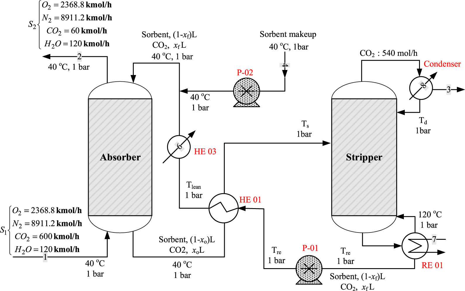
A schematic flow sheet of the CO2 capture process is shown in Figure 1. The process is a combination of an absorber and a stripper column. In the absorber, a lean sorbent is used to remove the CO2 associated with the sour gas in a 40-stage column. The spent sorbent is regenerated in the stripper, where the exact amount of captured CO2 is released with the top product. The regenerated solvent is recycled back into the absorber. In this work, the stripper is treated as an atmospheric flash drum where the amount of CO2 to be released occurs at specific VLE conditions. The baseline operating conditions for this process are listed in Table 1. These data are selected based on our previous work [53] and are in the range used in literature [49]. We assumed that only CO2 is miscible in the solvent (MTPB-MEA DES), the liquid species transferred to the gas phase are insignificant, the CO2 absorption is only because of physical interactions, and no chemical reactions occur.

Schematic of CO2 capture process using DES.
Baseline operating condition for the CO2 capture process [53]
| Gas feed rate (kmol‧h−1) | 12,000 |
| CO2 content (%) | 5 |
| H2O content (%) | 1 |
| Stripper operating pressure (atm) | 1 |
| Number of stages in the absorber | 40 |
Indeed, as shown in our previous work [52], samples of the DES before and after the absorption of the CO2 were analyzed using high-performance liquid chromatography (HPLC) and the results showed that only 10% of the amine reacted with the CO2, while for the aqueous solution of MEA, all of the amines reacted with the CO2. On the other hand, the detailed design equations and solution methodology of the process are given in our previous work [53]. The numerical solution for the baseline conditions is shown in Figure 1.
In the classical MEA process, the reboiler temperature is limited to 120°C because of the amine thermal instability above this temperature [54]. However, to evaluate the thermal stability of the DES used in this work, we performed a thermogravimetric analysis (TGA) under a nitrogen atmosphere using a Mettler Toledo TGA/DSC instrument. The results obtained are provided as supporting material (Figure A1 in Appendix). This analysis indicates two decomposition temperatures: one corresponding to the decomposition of MEA (at about 150°C) and the other corresponding to the decomposition of MTPB at a much higher temperature (at about 400°C). Therefore, the CO2 capturing process that runs with this solvent could operate at a higher temperature than the classical MEA aqueous process.
Table 2 lists the process performance at different selected operating pressures for the absorber column. The required liquid sorbent, the lean and rich solvent loadings, and the necessary stripping temperature are estimated at each operating pressure. The results in Table 2 form the baseline for the intended exergy analysis. Figure 2 illustrates the process performance with variable absorber pressures. The required solvent amount increases dramatically at low absorber vessel pressures because, at low pressure, the solubility of CO2 in the DES diminishes. Therefore, an additional quantity of solvent is needed to achieve an exact recovery rate of 90%. Similarly, Figure 2 demonstrates how the stripping temperature necessary for separating the captured CO2 from the spent sorbent lowers with pressure. The stripping temperature increases because of the amplification in the solvent circulation rate. Consequently, the rich loading decreases, and a much deeper lean is necessary, demanding additional energy to release the captured CO2.
The performance of CO2 capture process at selected absorber pressure values with 90% recovery
| P (atm) | x f | x o | L/G | L (kmol‧h−1) | T s (°C) | Stream 3 | Stream 4 makeup (kmol‧h−1) | |
|---|---|---|---|---|---|---|---|---|
| CO2 (kmol‧h−1) | DES (kmol‧h−1) | |||||||
| 10 | 0.0089 | 0.0683 | 0.75 | 9,015 | 66 | 540 | 2.5 | 2.5 |
| 7 | 0.0044 | 0.0332 | 1.55 | 18,619 | 126 | 540 | 64.0 | 64.0 |
| 5 | 0.0022 | 0.0198 | 2.55 | 30,606 | 162 | 540 | 413.1 | 413.1 |
| 2.2 | 0.0003 | 0.0041 | 12.05 | 144,588 | 186 | 540 | 5,028.9 | 5,028.9 |

CO2 capture process performance at selected values for P a using DES: squares for 90% recovery and circles for varied recovery.
Our simulation indicates that 90% of the CO2 recovery cannot be achieved by using DES at an absorber pressure of less than 2.2 atm. Furthermore, the simulation results revealed that the process operation below 7 atm is not physically acceptable because the required flashing temperature is beyond the boiling point of the applied DES. Therefore, the simulation was repeated, incorporating a flashing temperature constraint. Table 3 and Figure 2b show the results. The simulation results when operating at a low absorber pressure and a flashing temperature less than the DES boiling point of 155°C are shown in Table 3. At P a = 5 atm, the recovery must be lowered to 80% or less to ensure a low stripping temperature. Similarly, at P a = 3 atm, 60% is the maximum allowable recovery that guarantees a stripping temperature below 155°C.
The performance of CO2 capture process at low recovery rate
| P (atm) | Recovery | x f | x o | L/G | L (kmol‧h−1) | T s (oC) | Stream 3 | Makeup (kmol‧h−1) | |
|---|---|---|---|---|---|---|---|---|---|
| CO2 (kmol‧h−1) | DES (kmol‧h−1) | ||||||||
| 5 | 80% | 0.0044 | 0.0200 | 2.55 | 30,612 | 125 | 480 | 55.83 | 55.83 |
| 3 | 60% | 0.0031 | 0.0074 | 7.05 | 84,624 | 147 | 360 | 124.6 | 124.6 |
Furthermore, it is found that operating the absorber vessel at a pressure lower than 3 atm does not allow for a flashing temperature less than the boiling point, even at exceptionally low recovery rates.
An absorber column operating at 3 atm is not economically appealing from an energy consumption standpoint because it requires a high stripping temperature. Operating at this low pressure (less than 7 atm) could result in additional costs, such as the cost of materials and pumping. The results in Tables 2 and 3 indicate that the solvent flow rate could reach up to 13 times that required at P a = 10 atm. Furthermore, the process is operating at a lower recovery rate. Notably, although the process efficiency at low pressure is unappealing, it will be included in the following exergy analysis for demonstration purposes.
3 Exergy principles
Exergy is defined as the maximum possible reversible work that can be obtained from a system or a process. It is useful to measure and compare the energy efficiency of different processes or a process with different configurations [55,56]. Exergy analysis could identify areas of improvement and indicates the priorities toward efficiency enhancement and optimization, which are essential for the creation of new engineering decisions toward sustainable development.
The general exergy (Ex) expression is given by Eq. 1:
were H 0 and S 0 represent the enthalpy and entropy values, respectively, at the environmental temperature T 0, which is usually equal to 298 K. H and S represent the enthalpy and entropy, respectively, at a specified temperature, T (K).
All the processes involve the conversion and consumption of exergy; thus, high efficiency is critical, implying that the exergy use is managed and effective tools are applied. Although the total energy is always conserved, real process exergy is never balanced because of being irreversible, i.e., exergy destruction always occurs. The exergy destruction, ΔE, indicates possible process improvements. In engineering, different flow diagrams are often used to describe the different exergy flows through a process, enabling the selection of the process presenting the least exergy destruction. Generally, the exergy destruction or loss can be written as follows:
where m i and m 0 represent the mass input and output to the system, Q is the heat flow to the system, and W is the workflow to the system.
If the system is adiabatic (Q = 0) and does not require any work (W = 0), then Eq. 2 becomes Eq. 3:
The standard conditions considered in this work are T 0 = 298 K and P 0 = 1 atm.
4 Enthalpy and entropy change calculations
The estimation of exergy requires calculating the enthalpy and entropy of the fluids involved in the process. For the fluids used in the system, such as water and the liquid solvent, the enthalpy and entropy are functions of the temperature only, which could be calculated using the following equations for constant heat capacity:
For compressible gases at the elevated pressure, the enthalpy can be calculated as follows:
where the residual property can be calculated from the following correlation [49]:
Similarly, the gas entropy can be found using Eq. 8:
Eqs. 6–9 allow the calculation of enthalpy and entropy changes for any temperature and pressure variation.
The energy required for fluid pumping is calculated using Eq. 10:
In Eq. 10, Q is the volumetric flow rate in cubic meters per second, ΔP is the pressure difference in pascals, and η p is the pump efficiency. Similarly, the energy required for gas compression can be calculated using Eq. 11:
where m is the mass flow rate of the gas, H is the specific enthalpy for the inlet and outlet streams, and η c is the compressor efficiency.
5 Results and discussion
5.1 Effect of operating conditions for the baseline case
Figure 1 illustrates the CO2 capture flowsheet utilizing the DES solvent, which shows the operating parameters of all streams. The absorber operating pressure (P a) and stripper working temperature (T s) are predetermined, as shown in Tables 2 and 3. The temperature of the stream leaving HE01 and entering HE03 is arbitrarily set at 35°C, whereas T 2 is determined using an enthalpy balance around HE01. T1, the temperature of the gases exiting the compressor, was computed in the same way using the isentropic compression equation:
where γ is the heat capacity ratio equals C p /C v. We assume that the temperature change of the liquid solvent during compression through pumps P01 and P02 and expansion through valves V01 and V02 is negligible. Notably, water is used as a cooling medium in HE03 and HE04. The energy balance around each heat exchanger determines the amount of water used by using arbitrarily fixed temperatures for the inlet and outlet water streams. For HE02, hot water is used for heating when the required stripping temperature is less than 100°C. When T s exceeds 100°C, as shown in Table 2 for different values for P a, saturated steam is used to heat the rich sorbent stream. The amount of heating water or steam is computed using the energy balance around HE02. The steam temperature and pressure used for the different values of P a are taken from the steam tables. The temperature of the steam used in HE02 is chosen to be slightly higher than the required stripping temperature at the corresponding P a, e.g., when T s = 126°C, steam at 133.6°C is used. The physical properties of the DES used in this work and MEA are provided in supporting material (Table A1 in Appendix). In this work, the pump efficiency is taken at 60%, and the compressor efficiency is considered to be 70%.
5.2 Exergy analysis of DES-based CO2 capture process
After determining all flow rates and operating parameters with DES as the solvent (Table A2), we performed an exergy analysis for the overall process denoted by the dotted boundary in Figure 1. In this case, the exergy analysis included all streams that cross the boundary (streams 1–4). Therefore, Eq. 2 incorporates the contribution of heat exchangers and compressors to overall exergy loss in which case Table 4 and Figure 3 show the results.
Exergy flow and overall exergy loss of CO2 capture process
| Solvent | P a | T s | Exergy flow in streams and units | Overall | |||||||||||
|---|---|---|---|---|---|---|---|---|---|---|---|---|---|---|---|
| S1 | S2 | S3 | S4 | HE2 | HE3 | HE4 | C01 | Reb | Cond | Exin | Exout | ∆EX | |||
| (atm) | (°C) | (MW) | (MW) | (MW) | (MW) | (MW) | (MW) | (MW) | (MW) | (MW) | (MW) | (MW) | (MW) | (MW) | |
| DES | 3 | 147.8 | 0.00 | 8.82 | 0.26 | 0.00 | 6.70 | −0.38 | −0.35 | 10.64 | — | — | 17.33 | 9.80 | 7.53 |
| 5 | 125.2 | 0.00 | 12.78 | 0.15 | 0.00 | 1.74 | −0.14 | −0.55 | 16.77 | — | — | 18.51 | 13.62 | 4.89 | |
| 7 | 125.6 | 0.00 | 15.36 | 0.18 | 0.00 | 0.75 | −0.08 | −0.70 | 21.28 | — | — | 22.03 | 16.32 | 5.71 | |
| 10 | 65.6 | 0.00 | 18.17 | 0.02 | 0.00 | 0.23 | −0.04 | −0.87 | 26.51 | — | — | 26.75 | 19.11 | 7.64 | |
| 10 + ERD | 65.6 | 0.00 | 0.00 | 0.02 | 0.00 | 0.23 | −0.04 | −0.88 | 5.25 | — | — | 5.48 | 0.94 | 4.54 | |
| MEA | 1 | 40 | 0.04 | 0.04 | 0.018 | 4 × 10⁻⁵ | — | −0.211 | — | — | 6.26 | −0.64 | 6.5 | 0.8 | 5.7 |

Exergy destruction of the CO2 capture process using DES at selected pressure values.
Figure 3 shows that the system’s exergy destruction to exergy input decreases with operating pressure but increases again at P a = 10 atm. To achieve a high recovery rate and the lowest exergy losses, the absorber should be operated at P a = 7 atm. Examining the precise exergy flow in Table 4 can help you understand the exergy trend with pressure. Because the stripping temperature reaches 148°C at P a = 3 atm, the thermal energy consumption for heating the rich sorbent in HE2 is the highest. As a result, the equivalent gross exergy loss is the greatest. However, for P a = 10 atm, the work for compressing the flue gas takes precedence over the stripping energy. The additional compression work raises the net exergy destruction once again. As a result, the compression and heat energies must be balanced. As previously stated, running at low absorber pressures is undesirable due to the increased solvent circulation rate and low CO2 removal efficiency. Table 4 depicts the exergy flow linked with the process streams. Because of its high pressure, stream 2, the sweetened gas stream, has the largest exergy flow of the other streams. As the pressure decreases, so does the exergy.
It is useful to exploit the large exergy leaving the system by stream 2. The energy consumption when the process is operating at 10 atm (or higher) could be reduced by using the exergy associated with stream 2. This could be achieved by using a dual-work exchanger energy recovery system. These low-cost energy recovery devices (ERDs) provide greater energy-saving payback and greater operational flexibility for liquids [57,58].
A similar idea is utilized for gases, consisting of a gas turbine (expander) followed by a gas compressor. The power created by the gas turbine is utilized to power the following compressor, which pressurizes another low-pressure gas stream in this device. This device is also known as the gas pressure exchanger or booster, adopting the fundamentals of turbochargers in combustion engines. The so-called ERD for gases is proven useful in industry, for example, in ammonia factories. The purpose of this equipment is to recover energy from the pressurized fluid stream leaving the absorber column. The modified process is shown in Figure 4. Usually, such devices are limited by thermodynamic efficiency; therefore, the pressure of the exiting stream would be less than the inlet pressure of the pressurized stream. For an ERD efficiency of 60%, the pressure of the gas stream exiting the ERD can be 6.3 atm and the corresponding temperature 217°C. In this case, a compressor is still needed to complement the ERD. The main advantage of the modified process is that the purified gas stream exits the process at 1 atm. Consequently, the calculated overall exergy of the modified process is 6.36 MW.

Schematic of CO2 capture process using DES with the aid of ERD.
By using the pressure of the exit gas stream with an ERD efficiency of 60%, the process changed from an exergy deficit of 7.64 to 6.36 MW, which is equivalent to a 17% enhancement because the energy recovery in the form of the pressure head within the whole system enhances the conservation of exergy (decrease in exergy loss). If the ERD efficiency can be increased further, the performance of the DES process regarding exergy losses could be enhanced substantially (Table 5). This situation makes the DES-driven CO2 capture process, supported by the energy recovery system, more energy efficient. Usually, the sour gas treated for CO2 removal is the exhaust gas of a power plant. The flue gas leaves the combustion chamber of a power plant at an elevated temperature and pressure (1,494°C and 30 bar, respectively) [59,60]. The immense potential energy of the flue gas is usually used in power plants to produce high-pressure steam. Therefore, the exergy loss due to the compression work can be avoided by integrating the DES-driven CO2 capture process with the power plant.
Performance of DES + ERD at 10 atm and different ERD efficiency
| Efficiency (%) | ∆EX (MW) | En (MJ‧kg CO2 −1) |
|---|---|---|
| 50 | 8.370 | 3.041 |
| 60 | 6.357 | 2.060 |
| 70 | 4.542 | 1.400 |
| 80 | 2.884 | 0.935 |
5.3 Energy analysis of DES-based CO2 capture process
To further analyze the energy requirements of CO2 capture using DES, the specific energy of each thermal processing unit in the process was analyzed for an absorber operating at 10 and 3 atm. The calculating formulas have been presented in Section 4. The specific energy of captured CO2, which is a common way to easily compare processes with different capacities or efficiencies, is presented in Table 6. The pump power is the energy required to increase the pressure of the fluid. We neglect the pumping energy required to maintain the circulation rate and to overcome the pressure drop arising from distance, elevation, friction, or equipment. Therefore, the pumping energy for MEA and DES processes is almost null and, thus, is omitted.
Units’ specific energy requirement for CO2 capture process
| Process unit | DES (3 atm) | DES (10 atm) | DES + ERD (10 atm) | MEA (1 atm) |
|---|---|---|---|---|
| Energy | Energy | Energy | Energy | |
| (MJ‧kg CO2 −1) | (MJ‧kg CO2 −1) | (MJ‧kg CO2 −1) | (MJ‧kg CO2 −1) | |
| C01 | 3.449 | 5.735 | 1.162 | — |
| HE02 | 4.844 | 0.238 | 0.238 | — |
| HE03 | −5.253 | −0.372 | −0.372 | −1.57 |
| HE04 | −2.431 | −4.065 | −4.089 | — |
| Rebolier | — | — | — | −2.00 |
| Condenser | — | — | — | 5.8 |
The energy consumption of the gas compressor is the highest and can rise to around 6.0 MJ‧kg CO2 −1 at P a = 10 atm. Consequently, HE04 produces a large amount of energy because it absorbs the compression energy. The compression energy can be reduced by 40% when the pressure is cut to 3 atm. However, at that operating pressure, the specific heating energy of HE02 increases dramatically because of the elevated solvent circulation rate, elevated stripping temperature, and reduced CO2 recovery. In this case, the total specific energy consumption could be higher at a lower operating pressure. Similarly, the cooling energy of HE03 increases because of the elevated solvent circulation rate and reduced CO2 recovery. At P a = 10 atm, gas compression consumes the largest energy compared with other units, creating an energy-intensive requirement for CO2 capture by DES solvents at elevated pressures. At lower operating pressures, the energy demand for compression improves slightly, but the energy needed by HE02 increases substantially because of the excess heating requirements from the heating medium, leaving the system with a significant exergy loss.
The net energy requirements sum to 8.3 MJ‧kg CO2 −1 at P a = 3 atm, compared with 6 MJ‧kg CO2 −1 at P a = 10 atm. This makes operating at low absorber pressures more energy intensive than operating at a higher pressure. Although coolers HE3 and HE4 provide an abundance of energy suitable for heat integration, their energy cannot be used for heat recovery because the temperature of their corresponding operating streams is much less than T s. As mentioned earlier, the ERD unit can be incorporated, leading to dramatic energy saving as the specific energy of compression is reduced from 5.74 to 1.16 MJ‧kg CO2 −1, and hence, the net energy requirement becomes approximately 1.4 MJ‧kg CO2 −1. Furthermore, as shown in Table 5, if ERD devices with an efficiency higher than 60% are available, implementing such a device could make the DES process more efficient regarding exergy destruction and specific energy consumption.
5.4 Exergy analysis of MEA-based CO2 capture process
For benchmarking purposes, we studied the exergy of the CO2 capture process using MEA as the solvent. The process flowsheet is depicted in Figure A2. The MEA process has additional reboiler and condenser units. The sorbent preheater (HE02) is not used here because the regenerated solvent stream has sufficient thermal energy to heat the rich solvent stream. In such processes, CO2 extraction from flue gases is based on chemical absorption. Thus, additional energy is needed to break the reaction bonds and regenerate the solvent. We consider the same CO2 recovery ratio (90%), flue gas composition and amount, solvent circulation rate, and CO2 input for a fair comparison with the DES-operated process. The solvent circulation rate and its composition should be recalculated for the MEA-driven process. However, these variables do not affect the overall exergy calculation and are only useful when computing T lean. Table A2 shows the operating conditions of various process streams that are either taken from the literature or fixed at arbitrary values.
The temperature of the liquid stream exiting HE01 and entering HE03 is denoted as T lean and determined by the enthalpy balance around HE01. The enthalpy balance determines the amount of coolant water in HE03 by using a fixed arbitrary temperature for the coolant end-streams. Saturated steam of 130°C will be used in the reboiler. The reboiler duty is equal to 5.8 MJ‧kg CO2 −1 and that for the condenser is 2.07 MJ‧kg CO2 −1 [49]. The necessary physical properties of MEA are presented in Table A1. The reboiler temperature ranges from 90°C to 120°C, with a common value of 120°C [58,59]. The stripper inlet temperature can vary from 75°C to 120°C [59,61,62,63,64]. The reported value for the distillate temperature is either 75°C [49,63] or 107°C [56].
For simplicity, the stripper top vapor was set to 100°C to be consistent with the other stripper terminal values. Still, the temperature of the stripper surroundings has a marginal effect on the exergy calculations. For example, T d has a negligible effect on the exergy analysis because its corresponding flow rate is low, and T s is only required for estimating T lean. The top and bottom temperatures are not needed because the reboiler and condenser duties are sufficient to conduct the energy analysis. As mentioned earlier, we assume that the effect of compression and expansion of the liquid solvent on the temperature is negligible. The MEA solvent is a 30 wt% water solution. By applying the exergy equations to the CO2 capture process using MEA and on the basis of the aforementioned operating conditions, we obtained an overall exergy destruction of 5.7 MW (Table 4). Note that Table 4 presented negative values, indicating cooling, and, hence, the exergy flow for the corresponding unit will be considered as exergy flowing out of the system boundary. The calculated exergy is somehow subject to the operating conditions used; however, it indicates a better energy efficiency than using DES at P a = 10 atm and similar energy efficiency when compared with DES operating at 7 atm. When ERD is used, the DES-driven process can be more effective than the MEA method. Furthermore, the exergy input into the MEA process is lost inside the system because it is used to break the chemical reaction bonds to regenerate the solvent. In the DES process, the exergy input via the compressor to pressurize the sour gas enhanced the mass transfer of CO2 and, simultaneously, was transferred to the outlet stream (stream 2). The transferred energy can be further used within the process or further downstream.
5.5 Energy analysis of MEA-based CO2 capture process
The total energy consumption of a typical CO2 capture process is the sum of the thermal energy of regeneration, CO2 product compression, and solvent circulation. The regeneration energy causes a major part of the overall operating cost [65]. Therefore, we consider the reboiler thermal energy in the MEA process as the baseline for comparison and analysis. Similarly, the compression work in the DES process comprises most of the energy requirements that are equivalent to the reboiler duty in the MEA process. Therefore, operating the DES process at 10 atm requires equivalent specific energy to that of the counterpart MEA process. For example, Øi [59] and Øi and Kvam [66] reported an energy requirement of approximately 3.4 MJ‧kg−1 CO2 for a CO2 removal of 85%; Abu-Zahra et al. [65] reported an energy consumption in the range of 3.6–4.8 MJ‧kg−1 CO2 depending on the operating pressure and temperature; Han et al. [63] found that energy consumption of 4.3 MJ‧kg CO2 −1 resulted in up to 83% recovery, and Mofarahi et al. [49] recorded the highest reboiler duty of 5.8 MJ‧kg CO2 −1 for CO2 recovery of 89%. Rao and Rubin [67] reported a reboiler heat duty range of 1.6–11 MJ‧kg CO2 −1 for a recovery range of 41–99.9%.
Another source of energy consumption in DES-based processes is the additional energy for solvent circulation to overcome the pressure drop arising from the viscosity. The viscosity of DES is higher than that of MEA (Table A1). Estimating the increased energy required due to viscosity is difficult since it requires particular design factors such as pipe diameter, length, and elevation. However, we can roughly assume that the additional energy required by DES circulation over that of MEA is proportional to their viscosity ratio, which is approximately 2.4.
5.6 Comparison between MEA and DES processes for small-scale CO2 capture plant
Previous MEA exergy analyses relied on design data, notably the solvent circulation rate and CO2 loading, which are calculated by solving design equations with DES as the solvent. It is worthwhile to review the MEA exergy study based on design data calculated using the MEA solvent. The design data for the MEA method proposed by Li et al. [68] are shown in Table A3. The data provided are sufficient for the overall exergy analysis but not for the unit-by-unit exergy analysis required for the MEA procedure. Notably, in the designated references, the initial feed composition and CO2 loading are reported in grams per gram. To fit our modeling approach, these values are transformed into moles.
For comparison with the DES-driven process, our DES design model will be solved using the given data for the gas flow rate, solvent flow rate, feed composition, and the desired CO2 removal rate to determine the stripping temperature and CO2 loadings. The other necessary operating conditions that are either fixed at arbitrary values or calculated as indicated are listed in Table A4. Notably, our simulation of the DES process indicated that the operating pressure for the absorber must be larger than 10 atm to maintain a stripping temperature below 155°C. For the given low CO2 content in the flue gas and low CO2 loadings, controlled by the CO2 fraction in the outlet sweetened gas, the stripper requires high energy to extract the low CO2 content from the diluted solvent. After applying the exergy analysis to the MEA and DES processes, the results presented in Table 7 were obtained. The MEA process has much lower exergy destruction than the DES process. Most of the exergy losses in the MEA process originate from the reboiler, whereas, for the DES case, the compression work is the dominant source of exergy destruction. However, when relating the exergy losses to the exergy added to the system, the MEA process becomes inferior to the DES process.
Exergy analysis for the MEA and DES processes
| P a (atm) | Ta (K) | S1 (kW) | S4 (kW) | S2 (kW) | S3 (kW) | HE2 (kW) | HE3 (kW) | HE4 (kW) | Com (kW) | Re (kW) | Con (kW) | Ex in (kW) | Ex out (kW) | ∆EX (kW) | |
|---|---|---|---|---|---|---|---|---|---|---|---|---|---|---|---|
| DES | 20 | 320 | 0.018 | 0.000 | 5.260 | 0.001 | 0.247 | −0.126 | −0.363 | 12.79 | — | — | 13.056 | 5.750 | 7.31 |
| 15 | 320 | 0.018 | 0.000 | 4.775 | 0.006 | 0.498 | −0.126 | −0.313 | 11.09 | — | — | 11.607 | 5.220 | 6.39 | |
| 20ERD | 320 | 0.018 | 0.000 | 0.017 | 0.001 | 0.247 | −0.126 | −0.032 | 1,013 | — | — | 1.277 | 0.177 | 1.10 | |
| MEA* | 1 | 320 | 0.018 | 0.000 | 0.017 | 0.000 | — | −0.177 | — | — | 2.083 | −0.215 | 2.101 | 0.409 | 1.69 |
*[68]
Our DES design model was solved using the given data for the gas flow rate, solvent flow rate, feed composition, and desired CO2 removal rate to estimate the stripping temperature and CO2 loadings for comparison with the DES-driven process. Table A4 lists the additional required operating conditions, which are either fixed at arbitrary values or calculated as specified. Notably, our simulation of the DES process revealed that the operating pressure for the absorber must be more than 10 atm to keep the stripping temperature below 155°C. The stripper requires a lot of energy to extract the low CO2 content from the diluted solvent for the specified low CO2 content in the flue gas and low CO2 loadings, which are controlled by the CO2 percentage in the outlet sweetened gas. The results presented in Table 7 are obtained after applying the exergy analysis to the MEA and DES procedures. The MEA process consumes far less energy than the DES procedure. The reboiler accounts for the majority of exergy losses in the MEA process, whereas the compression work is the primary source of exergy destruction in the DES process. However, when the exergy losses are compared to the exergy added to the system, the MEA process falls short of the DES process.
As previously stated, exergy added to the MEA process is lost within the system, whereas exergy added to the DES process is transferred to the outlet stream in part. As a result, the relocated exergy can be employed further inside the system via pressure recovery units, resulting in increased energy efficiency. Table 8 compares the energy consumption of the MEA and DES procedures. Depending on the operating pressure, the DES process may take up to 34–38 MJ‧kg CO2 −1. The MEA system, on the other hand, consumes just 19 MJ‧kg CO2 −1, providing for 50% of the reduction in energy requirement.
Comparison between the specific energy demand of the MEA and DES processes
| Parameter | DES | MEA* | ||
|---|---|---|---|---|
| P a (atm) | 20 | 15 | 20 + ERD | 1 |
| T s (°C) | 60.6 | 107.7 | 60.6 | 120.8 |
| Comp (MJ‧kg CO2 −1) | 31.7 | 27.5 | 2.46 | — |
| HE02 (MJ‧kg CO2 −1) | 5.8 | 5.6 | 5.80 | — |
| HE03 (MJ‧kg CO2 −1) | −5.8 | −5.8 | −5.79 | −7.8 |
| HE04 (MJ‧kg CO2 −1) | −23.2 | −20.0 | −2.04 | — |
| PE01 (MJ‧kg CO2 −1) | 1.7 | 1.3 | 1.73 | 0 |
| PE02 (MJ‧kg CO2 −1) | 0.0 | 0.0 | 0.00 | 0 |
| Cond (MJ‧kg CO2 −1) | — | — | — | — |
| RE01 (MJ‧kg CO2 −1) | — | — | — | 19.01 |
*[68]
To compete with the MEA-based process in terms of energy usage, the DES-based process should be run at a low absorber pressure. However, while operating at low pressures, our simulation results show a performance constraint in the form of a poor recovery or stripping temperature over the solvent’s boiling point. Otherwise, if the benefits of running at greater pressure, such as reduced solvent circulation rate and lower stripping temperature, are desired, an ERD unit can be added to the process. For example, with a 60% ERD, the compression work might be lowered to 0.66 MJ‧kg CO2 −1 for the baseline scenario and 2.46 MJ‧kg CO2 −1 for Li et al.’s [68] procedure, representing an 80–90% improvement. Alternatively, the inherited pressure of a power plant’s flue gas might be used to replace the compression unit. For highly pressurized sour gases, the DES-based technique is preferred.
6 Conclusions
The energy demand of CO2 removal from flue gas using amine-based DESs in the absorption–desorption process was investigated in this work. High absorption column pressures are required to provide effective CO2 physical absorption and, as a result, improved process performance and design requirements. Depending on the processing capacity and operating pressure, the raised pressure increases the exergy deficit to 4–8 MW and the energy consumption to roughly 6–38 MJ‧kg CO2 −1. We discovered that the main source of exergy shortage is the compression energy of the flue gas. However, when compared to the MEA-based process, it was found that the DES-based process has a lot better exergy destruction because the exergy inserted is much superior to the exergy lost in the DES process. The energy demand of the MEA process, on the other hand, was discovered to be nearly 50% lower than that of the DES process, where the energy consumption is mostly related to the compression work to the required high pressure. Adding an ERD unit can lower the DES process’s energy need by up to 80%. To improve the process economically, we recommend lowering the operating pressure, which reduces exergy loss at the expense of performance. Alternatively, ERDs could be incorporated into the process to reduce compression demand and, as a result, exergy loss. Nonetheless, when applied to contaminated exhaust gases at high pressure, the DES-driven CO2 capture process could be energy efficient. The study’s major goal is to identify a less energy-intensive CO2 capture technique than the standard MEA solvent. DES solvents are used to alleviate this. However, the suggested DES process necessitates high-pressure operation to maintain the same CO2 recovery and solvent-to-gas ratios as the standard MEA method, resulting in increased energy consumption owing to flue gas compression. Yet, by employing an ERD, the DES process can outperform the conventional technique. These encouraging findings pave the way for additional research into alternatives to standard MEA solvents.
Acknowledgments
The authors thank the National Plan for Science, Technology, and Innovation (NPSTI, KACST) for supporting this work through project number 14-ENV-1934-02. They also extend their gratitude to the Researchers Support and Services Unit (RSSU) for their technical support.
-
Funding information: This work was supported by the National Plan for Science, Technology and Innovation, KACST (Grant Numbers 14-ENV-1934-02).
-
Author contributions: Emad Ali: conceptualization, writing – original draft, writing – review and editing, and methodology; Mohamed K. Hadj-Kali: conceptualization, formal analysis, writing – review and editing, project administration, and funding; Salim Mokraoui: writing – review and editing and formal analysis; Rawaiz Khan: methodology, writing – review and editing, and visualization; Meshal Aldawsari: resources and writing – review and editing; Mourad Boumaza: methodology, formal analysis, and review.
-
Conflict of interest: The authors state no conflict of interest.
-
Data availability statement: All data generated or analyzed during this study are included in this published article and its supplementary information files.
Appendix
There are two degradation steps of MTPB-MEA indicated as point 1 and point 2. Point 1 with onset at ∼150°C is likely associated with the degradation of amine functionality. Point 2 with an onset at ∼400°C is likely associated with the degradation of bromide functionality. The MTPB-MEA DES is thermally stable up to 150°C.

TGA of MTPB-MEA (1:6) deep eutectic solvent.
physical properties of DES and MEA
| Solvent | M w (g‧mol−1) | Density (kg‧m−3) | C p (J‧g−1‧K−1) | Viscosity (cP) | T n (°C) |
|---|---|---|---|---|---|
| DES | 103.38 | 1,120 | 1.91 | 42.9 | 155 |
| MEA | 61.08 | 1,010 | 3.1* | 17.9 | 170 |
* [62]
Operating condition for conducting exergy and energy analysis
| DES | MEA | |||||
|---|---|---|---|---|---|---|
| P a (atm) | 3 | 5 | 7 | 10 | 10 + ERD | 1 |
| T a (°C) | 25 | 25 | 25 | 25 | 25 | 40 |
| T s (°C)c | 147 | 125 | 125 | 65 | 65 | 105r1 |
| mH2 (kg‧kg CO2 −1)c | 2.28 | 0.49 | 0.19 | 2.69 | 2.69 | — |
| mH3 (kg‧kg CO2 −1)c | 125.68 | 34.05 | 18.38 | 8.89 | 8.89 | 37.54 |
| mH4 (kg‧kg CO2 −1)c | 29.08 | 34.45 | 38.93 | 48.62 | 5.74 | — |
| THE2i (°C)a | 151 | 133 | 133 | 80 | 80 | — |
| THE2o (°C)a | 151 | 133 | 133 | 60 | 60 | — |
| THE3i (°C)a | 20 | 20 | 20 | 20 | 20 | 35 |
| THE3o (°C)a | 30 | 30 | 30 | 30 | 30 | 45 |
| THE4i (°C)a | 15 | 15 | 15 | 15 | 15 | — |
| THE4o (°C)a | 35 | 35 | 35 | 35 | 35 | — |
| T 1 (°C)c | 130 | 190 | 234 | 284 | 285 | — |
| T 1i (°C) | -- | -- | -- | -- | 217 | -- |
| T 2 (°C)c | 143 | 121 | 122 | 62 | 62 | –- |
| T lean (°C)a | 30 | 30 | 30 | 30 | 30 | 58 |
| T st (°C)a | — | — | — | — | — | 100 |
| T sd (°C)a | — | — | — | — | — | 75 |
| T re (°C)r1 | — | — | — | — | — | 120 |
| Reboiler duty (MW‧kg CO2 −1)r2 | — | — | — | — | — | 2.07 |
| Condenser duty (MW‧kg CO2 −1)r2 | — | — | — | — | — | 5.8 |
Operating conditions for MEA process
| Parameter | [68] |
|---|---|
| G | 2.62 kmol‧h−1 |
| L | 8.47 kmol‧h−1 |
| Recovery rate | 90% |
| CO2 content in flue gas | 1.4% |
| H2O content in flue gas | 11% |
| O2 content in flue gas | 0.094 |
| N2 content in flue gas | 0.783 |
| CO2 mole fraction in rich sorbent | 0.039 |
| CO2 mole fraction in lean sorbent | 0.027 |
| Stripper top temperature | NA |
| Stripper inlet temperature | 112°C |
| Stripper bottom temperature | 119.8°C |
| Reboiler duty | 7.95 kW |
| Reboiler temperature | 120°C |
| Absorber temperature | 47°C |
| Absorber pressure | 1.1 bar |
| Solvent circulation temperature | 52°C |
| Condenser duty | 2.77 kW |
Schematic of CO2 capture process using MEA.
Design and operating condition from the process in Li et al. [68]
| Parameter | DES | MEA | ||
|---|---|---|---|---|
| Pa (atm) | 20 | 15 | 20 + ERD | 1 |
| Ta (°C) | 47 | 47 | 47 | 47 |
| Ts (°C) | 60 | 107 | 60 | 120 |
| mH2 (kg‧kg CO2 −1) | 68.7 | 2.5 | 68.7 | — |
| mH3 (kg‧kg CO2 −1) | 138.5 | 138.4 | 138.5 | 282.3 |
| mH4 (kg‧kg CO2 −1) | 277.9 | 239.3 | 24.4 | — |
| mCon (kg‧kg CO2 −1) | — | — | — | 119.4 |
| mReS (kg‧kg CO2 −1) | — | — | — | 13.2 |
| THE2i (°C) | 70.6a | 110a | 70.6 | — |
| THE2o (°C) | 50.6a | 110a | 50.6 | — |
| THE3i (°C) | 20a | 20a | 42 | 42a |
| THE3o (°C) | 30a | 30a | 52 | 52a |
| THE4i (°C) | 15a | 15a | 37 | — |
| THE4o (°C) | 35a | 35a | 57 | — |
| T1 (°C) | 443.6 | 392.5 | 79.5 | — |
| T2 (°C) | 55.6 | 102.9 | 55.6 | — |
| Tlean (°C) | 30 | 30 | 30 | 56.4 |
| Tsi (°C) | — | — | — | 112 |
| Tsb (°C) | — | — | — | 119 |
| Tst (°C) | — | — | — | 28a |
| Tsd (°C) | — | — | — | 18 |
-
a Assumed arbitrary.
References
[1] Höök M, Tang X. Depletion of fossil fuels and anthropogenic climate change – a review. Energy Policy. 2013;52:797–809.10.1016/j.enpol.2012.10.046Search in Google Scholar
[2] Jackson RB, Canadell JG, Le Quéré C, Andrew RM, Korsbakken JI, Peters GP, et al. Reaching peak emissions. Nat Clim Change. 2016;6(1):7–10.10.1038/nclimate2892Search in Google Scholar
[3] Le Quéré C, Andrew RM, Friedlingstein P, Sitch S, Pongratz J, Manning AC, et al. Global carbon budget 2017. Earth Syst Sci Data. 2018;10(1):405–48.10.5194/essd-10-405-2018Search in Google Scholar
[4] Le Quéré C, Andrew RM, Friedlingstein P, Sitch S, Hauck J, Pongratz J, et al. Global carbon budget 2018. Earth Syst Sci Data. 2018;10(4):2141–94.10.5194/essd-10-2141-2018Search in Google Scholar
[5] Etminan M, Myhre G, Highwood E, Shine K. Radiative forcing of carbon dioxide, methane, and nitrous oxide: A significant revision of the methane radiative forcing. Geophys Res Lett. 2016;43(24):614–2.10.1002/2016GL071930Search in Google Scholar
[6] Yamasaki A. An overview of CO2 mitigation options for global warming – emphasizing CO2 sequestration options. J Chem Eng Jpn. 2003;36(4):361–75.10.1252/jcej.36.361Search in Google Scholar
[7] Budinis S, Krevor S, Dowell NM, Brandon N, Hawkes A. An assessment of CCS costs, barriers and potential. Energy Strategy Rev. 2018;22:61–81.10.1016/j.esr.2018.08.003Search in Google Scholar
[8] Mirza NR, Nicholas NJ, Wu Y, Mumford KA, Kentish SE, Stevens GW. Experiments and thermodynamic modeling of the solubility of carbon dioxide in three different deep eutectic solvents (DESs). J Chem Eng Data. 2015;60(11):3246–52.10.1021/acs.jced.5b00492Search in Google Scholar
[9] Molina CT, Bouallou C. Assessment of different methods of CO2 capture in post-combustion using ammonia as solvent. J Clean Prod. 2015;103:463–8.10.1016/j.jclepro.2014.03.024Search in Google Scholar
[10] Vaidya PD, Kenig EY. CO2-alkanolamine reaction kinetics: a review of recent studies. Chem Eng Technol. 2007;30(11):1467–74.10.1002/ceat.200700268Search in Google Scholar
[11] Arias AM, Mores PL, Scenna NJ, Mussati SF. Optimal design and sensitivity analysis of post-combustion CO2 capture process by chemical absorption with amines. J Clean Prod. 2016;115:315–31.10.1016/j.jclepro.2015.12.056Search in Google Scholar
[12] Dinca C. Critical parametric study of circulating fluidized bed combustion with CO2 chemical absorption process using different aqueous alkanolamines. J Clean Prod. 2016;112:1136–49.10.1016/j.jclepro.2015.06.051Search in Google Scholar
[13] Zhang R, He X, Liu T, Li C, Xiao M, Ling H, et al. Thermodynamic studies for improving the prediction of CO2 equilibrium solubility in aqueous 2-dimethylamino-2-methyl-1-propanol. Sep Purif Technol. 2022;295:121292.10.1016/j.seppur.2022.121292Search in Google Scholar
[14] Chen G, Chen G, Peruzzini M, Zhang R, Barzagli F. Understanding the potential benefits of blended ternary amine systems for CO2 capture processes through 13C NMR speciation study and energy cost analysis. Sep Purif Technol. 2022;291:120939.10.1016/j.seppur.2022.120939Search in Google Scholar
[15] Mantripragada HC, Zhai H, Rubin ES. Boundary Dam or Petra Nova – which is a better model for CCS energy supply? Int J Greenh Gas Control. 2019;82:59–68.10.1016/j.ijggc.2019.01.004Search in Google Scholar
[16] Goto K, Yogo K, Higashii T. A review of efficiency penalty in a coal-fired power plant with post-combustion CO2 capture. Appl Energy. 2013;111:710–20.10.1016/j.apenergy.2013.05.020Search in Google Scholar
[17] Bougie F, Iliuta MC. Sterically hindered amine-based absorbents for the removal of CO2 from gas streams. J Chem Eng Data. 2012;57(3):635–69.10.1021/je200731vSearch in Google Scholar
[18] Novotny V, Vitvarova M, Kolovratnik M, Hrdina Z. Minimizing the energy and economic penalty of CCS power plants through waste heat recovery systems. Energy Procedia. 2017;108:10–7.10.1016/j.egypro.2016.12.184Search in Google Scholar
[19] Patiño-Echeverri D, Hoppock DC. Reducing the Energy Penalty Costs of Post Combustion CCS Systems with amine-Storage. Environ Sci Technol. 2012;46(2):1243–52.10.1021/es202164hSearch in Google Scholar PubMed
[20] Lail M, Tanthana J, Coleman L. Non-aqueous solvent (NAS) CO2 capture process. Energy Procedia. 2014;63:580–94.10.1016/j.egypro.2014.11.063Search in Google Scholar
[21] El Hadri N, Quang DV, Goetheer ELV, Abu Zahra MRM. Aqueous amine solution characterization for post-combustion CO2 capture process. Appl Energy. 2017;185:1433–49.10.1016/j.apenergy.2016.03.043Search in Google Scholar
[22] Zhao B, Sun Y, Yuan Y, Gao J, Wang S, Zhuo Y, et al. Study on corrosion in CO2 chemical absorption process using amine solution. Energy Procedia. 2011;4:93–100.10.1016/j.egypro.2011.01.028Search in Google Scholar
[23] Barzagli F, Lai S, Mani F. Novel non-aqueous amine solvents for reversible CO2 capture. Energy Procedia. 2014;63:1795–804.10.1016/j.egypro.2014.11.186Search in Google Scholar
[24] Guo H, Li C, Shi X, Li H, Shen S. Nonaqueous amine-based absorbents for energy efficient CO2 capture. Appl Energy. 2019;239:725–34.10.1016/j.apenergy.2019.02.019Search in Google Scholar
[25] Li X, Ding Y, Guo L, Liao Q, Zhu X, Wang H. Non-aqueous energy-efficient absorbents for CO2 capture based on porous silica nanospheres impregnated with amine. Energy. 2019;171:109–19.10.1016/j.energy.2018.12.175Search in Google Scholar
[26] Lv B, Guo B, Zhou Z, Jing G. Mechanisms of CO2 capture into monoethanolamine solution with different CO2 loading during the absorption/desorption processes. Environ Sci Technol. 2015;49(17):10728–35.10.1021/acs.est.5b02356Search in Google Scholar PubMed
[27] Tao M, Gao J, Zhang P, Zhang W, Liu Q, He Y, et al. Biogas upgrading by capturing CO2 in non-aqueous phase-changing diamine solutions. Energy Fuels. 2017;31(6):6298–304.10.1021/acs.energyfuels.7b00456Search in Google Scholar
[28] Aghel B, Janati S, Wongwises S, Shadloo MS. Review on CO2 capture by blended amine solutions. Int J Greenh Gas Control. 2022;119:103715.10.1016/j.ijggc.2022.103715Search in Google Scholar
[29] Hu X, Huang J, He X, Luo Q, Li C, Zhou C, et al. Analyzing the potential benefits of trio-amine systems for enhancing the CO2 desorption processes. Fuel. 2022;316:123216.10.1016/j.fuel.2022.123216Search in Google Scholar
[30] Pellegrini LA, Gilardi M, Giudici F, Spatolisano E. New solvents for CO2 and H2S removal from gaseous streams. Energies. 2021;14:6687.10.3390/en14206687Search in Google Scholar
[31] Yu YS, Lu HF, Zhang TT, Zhang ZX, Wang GX, Rudolph V. Determining the performance of an efficient nonaqueous CO2 capture process at desorption temperatures below 373 K. Ind Eng Chem Res. 2013;52(35):12622–34.10.1021/ie400353fSearch in Google Scholar
[32] Yu CH, Wu TW, Tan CS. CO2 capture by piperazine mixed with non-aqueous solvent diethylene glycol in a rotating packed bed. Int J Greenh Gas Control. 2013;19:503–9.10.1016/j.ijggc.2013.10.014Search in Google Scholar
[33] Im J, Hong SY, Cheon Y, Lee J, Lee JS, Kim HS, et al. Steric hindrance-induced zwitterionic carbonates from alkanolamines and CO2: highly efficient CO2 absorbents. Energy Environ Sci. 2011;4(10):4284–9.10.1039/c1ee01801aSearch in Google Scholar
[34] Chen S, Chen S, Fei X, Zhang Y, Qin L. Solubility and characterization of CO2 in 40 mass % N-Ethylmonoethanolamine solutions: Explorations for an efficient nonaqueous solution. Ind Eng Chem Res. 2015;54(29):7212–8.10.1021/acs.iecr.5b01654Search in Google Scholar
[35] Xiao M, Liu H, Gao H, Olson W, Liang Z. CO2 capture with hybrid absorbents of low viscosity imidazolium-based ionic liquids and amine. Appl Energy. 2019;235:311–9.10.1016/j.apenergy.2018.10.103Search in Google Scholar
[36] Cao J, Yang M, Cao F, Wang J, Su E. Tailor-made hydrophobic deep eutectic solvents for cleaner extraction of polyprenyl acetates from Ginkgo biloba leaves. J Clean Prod. 2017;152:399–405.10.1016/j.jclepro.2017.03.140Search in Google Scholar
[37] Niedermaier I, Bahlmann M, Papp C, Kolbeck C, Wei W, Krick CS, et al. Carbon dioxide capture by an amine functionalized ionic liquid: fundamental differences of surface and bulk behavior. J Am Chem Soc. 2014;136(1):436–41.10.1021/ja410745aSearch in Google Scholar PubMed
[38] Raja Shahrom MS, Wilfred CD, MacFarlane DR, Vijayraghavan R, Chong FK. Amino acid based poly(ionic liquid) materials for CO2 capture: effect of anion. J Mol Liq. 2019;276:644–52.10.1016/j.molliq.2018.12.044Search in Google Scholar
[39] Wang C, Luo H, Luo X, Li H, Dai S. Equimolar CO2 capture by imidazolium-based ionic liquids and superbase systems. Green Chem. 2010;12(11):2019–23.10.1039/c0gc00070aSearch in Google Scholar
[40] Luo X, Guo Y, Ding F, Zhao H, Cui G, Li H, et al. Significant improvements in CO2 capture by pyridine-containing anion-functionalized ionic liquids through multiple‐site cooperative interactions. Angew Chem. 2014;53(27):7053–7.10.1002/anie.201400957Search in Google Scholar PubMed
[41] Gutowski KE, Maginn EJ. Amine-functionalized task-specific ionic liquids: a mechanistic explanation for the dramatic increase in viscosity upon complexation with CO2 from molecular simulation. J Am Chem Soc. 2008;130(44):14690–704.10.1021/ja804654bSearch in Google Scholar PubMed
[42] Trivedi TJ, Lee JH, Lee HJ, Jeong YK, Choi JW. Deep eutectic solvents as attractive media for CO2 capture. Green Chem. 2016;18(9):2834–42.10.1039/C5GC02319JSearch in Google Scholar
[43] Uma Maheswari A, Palanivelu K. Carbon dioxide capture and utilization by alkanolamines in deep eutectic solvent medium. Ind Eng Chem Res. 2015;54(45):11383–92.10.1021/acs.iecr.5b01818Search in Google Scholar
[44] Zhang Q, De Oliveira Vigier K, Royer S, Jérôme F. Deep eutectic solvents: syntheses, properties and applications. Chem Soc Rev. 2012;41(21):7108–46.10.1039/c2cs35178aSearch in Google Scholar PubMed
[45] Li K, Yu H, Tade M, Feron P, Yu J, Wang S. Process modeling of an advanced NH3 abatement and recycling technology in the ammonia-based CO2 capture process. Environ Sci Technol. 2014;48(12):7179–86.10.1021/es501175xSearch in Google Scholar PubMed
[46] Abu-Zahra MRM, Schneiders LHJ, Niederer JPM, Feron PHM, Versteeg GF. CO2 capture from power plants: Part I. Int J Greenh Gas Control. 2007;1:37–46.10.1016/S1750-5836(06)00007-7Search in Google Scholar
[47] Li BH, Zhang N, Smith R. Simulation and analysis of CO2 capture process with aqueous monoethanolamine solution. Appl Energy. 2016;161:707–17.10.1016/j.apenergy.2015.07.010Search in Google Scholar
[48] Zhang Q, Turton R, Bhattacharyya D. Development of model and model-predictive control of an MEA-based post combustion CO2 capture process. Ind Eng Chem Res. 2016;55(5):1292–308.10.1021/acs.iecr.5b02243Search in Google Scholar
[49] Mofarahi M, Khojasteh Y, Khaledi H, Farahnak A. Design of CO2 absorption plant for recovery of CO2 from flue gases of gas turbine. Energy. 2008;33(8):1311–9.10.1016/j.energy.2008.02.013Search in Google Scholar
[50] Oh SY, Binns M, Cho H, Kim JK. Energy minimization of MEA-based CO2 capture process. Appl Energy. 2016;169:353–62.10.1016/j.apenergy.2016.02.046Search in Google Scholar
[51] Zhang W, Chen J, Luo X, Wang M. Modelling and process analysis of post-combustion carbon capture with the blend of 2-amino-2-methyl-1-propanol and piperazine. Int J Greenh Gas Control. 2017;63:37–46.10.1016/j.ijggc.2017.04.018Search in Google Scholar
[52] Ali E, Hadj-Kali MK, Mulyono S, Alnashef I, Fakeeha A, Mjalli F, et al. Solubility of CO2 in deep eutectic solvents: Experiments and modelling using the Peng–Robinson equation of state. Chem Eng Res Des. 2014;92(10):1898–906.10.1016/j.cherd.2014.02.004Search in Google Scholar
[53] Ali E, Hadj-Kali MK, Mulyono S, Alnashef I. Analysis of operating conditions for CO2 capturing process using deep eutectic solvents. Int J Greenh Gas Control. 2016;47:342–50.10.1016/j.ijggc.2016.02.006Search in Google Scholar
[54] Kohl AL, Nielsen R. Gas purification. 5th edn. Houston, Texas, USA: Gulf Professional Publishing; 1997.Search in Google Scholar
[55] Smith JM, Van Ness HC, Abbott MM. Introduction to chemical engineering thermodynamics. 8th Edn. Boston, USA: McGraw-Hill; 2018.Search in Google Scholar
[56] Wall G. Life cycle exergy analysis of renewable energy systems. Open Renew Energy J. 2011;4(1):1–6.10.2174/1876387101004010072Search in Google Scholar
[57] Kutz M. Mechanical engineers’ handbook, 1. Materials and engineering mechanics. New Jersey, USA: John Wiley & Sons; 2015.Search in Google Scholar
[58] Srivathsan G. Modeling of fluid flow in spiral wound reverse osmosis membranes. Ph.D. dissertation. USA: University of Minnesota; 2013.Search in Google Scholar
[59] Øi LE. Aspen HYSYS simulation of CO2 removal by amine absorption from a gas-based power plant. The 48th Scandinavian Conference on Simulation and Modeling (SIMS 2007). Linköping University Electronic Press; 2007. p. 73–81.Search in Google Scholar
[60] Pan M, Aziz F, Li B, Perry S, Zhang N, Bulatov I, et al. Application of optimal design methodologies in retrofitting natural gas combined cycle power plants with CO2 capture. Appl Energy. 2016;161:695–706.10.1016/j.apenergy.2015.03.035Search in Google Scholar
[61] Nuchitprasittichai A, Cremaschi S. Optimization of CO2 capture process with aqueous amines using response surface methodology. Comput Chem Eng. 2011;35(8):1521–31.10.1016/j.compchemeng.2011.03.016Search in Google Scholar
[62] Greer T. Modeling and simulation of post combustion CO2 capturing. Master thesis. Norway: Telemark University College; 2008.Search in Google Scholar
[63] Han C, Graves K, Neathery J, Liu K. Simulation of the energy consumption of CO2 capture by aqueous monoethanolamine in pilot plant. Energy Environ Res. 2011;1(1):67.10.5539/eer.v1n1p67Search in Google Scholar
[64] Kothandaraman A. Carbon dioxide capture by chemical absorption: a solvent comparison study. Ph.D. dissertation. USA: Massachusetts Institute of Technology; 2010.Search in Google Scholar
[65] Abu-Zahra MRM, Niederer JPM, Feron PHM, Versteeg GF. CO2 capture from power plants: Part II. Int J Greenh Gas Control. 2007;1(2):135–42.10.1016/S1750-5836(07)00032-1Search in Google Scholar
[66] Øi LE, Kvam SHP. Comparison of energy consumption for different CO2 absorption configurations using different simulation tools. Energy Procedia. 2014;63:1186–95.10.1016/j.egypro.2014.11.128Search in Google Scholar
[67] Rao AB, Rubin ES. Identifying cost-effective CO2 control levels for amine-based CO2 capture systems. Ind Eng Chem Res. 2006;45(8):2421–9.10.1021/ie050603pSearch in Google Scholar
[68] Li K, Cousins A, Yu H, Feron P, Tade M, Luo W, et al. Systematic study of aqueous monoethanolamine-based CO2 capture process: Model development and process improvement. Energy Sci Eng. 2016;4(1):23–39.10.1002/ese3.101Search in Google Scholar
© 2023 the author(s), published by De Gruyter
This work is licensed under the Creative Commons Attribution 4.0 International License.
Articles in the same Issue
- Research Articles
- Value-added utilization of coal fly ash and recycled polyvinyl chloride in door or window sub-frame composites
- High removal efficiency of volatile phenol from coking wastewater using coal gasification slag via optimized adsorption and multi-grade batch process
- Evolution of surface morphology and properties of diamond films by hydrogen plasma etching
- Removal efficiency of dibenzofuran using CuZn-zeolitic imidazole frameworks as a catalyst and adsorbent
- Rapid and efficient microwave-assisted extraction of Caesalpinia sappan Linn. heartwood and subsequent synthesis of gold nanoparticles
- The catalytic characteristics of 2-methylnaphthalene acylation with AlCl3 immobilized on Hβ as Lewis acid catalyst
- Biodegradation of synthetic PVP biofilms using natural materials and nanoparticles
- Rutin-loaded selenium nanoparticles modulated the redox status, inflammatory, and apoptotic pathways associated with pentylenetetrazole-induced epilepsy in mice
- Optimization of apigenin nanoparticles prepared by planetary ball milling: In vitro and in vivo studies
- Synthesis and characterization of silver nanoparticles using Origanum onites leaves: Cytotoxic, apoptotic, and necrotic effects on Capan-1, L929, and Caco-2 cell lines
- Exergy analysis of a conceptual CO2 capture process with an amine-based DES
- Construction of fluorescence system of felodipine–tetracyanovinyl–2,2′-bipyridine complex
- Excellent photocatalytic degradation of rhodamine B over Bi2O3 supported on Zn-MOF nanocomposites under visible light
- Optimization-based control strategy for a large-scale polyhydroxyalkanoates production in a fed-batch bioreactor using a coupled PDE–ODE system
- Effectiveness of pH and amount of Artemia urumiana extract on physical, chemical, and biological attributes of UV-fabricated biogold nanoparticles
- Geranium leaf-mediated synthesis of silver nanoparticles and their transcriptomic effects on Candida albicans
- Synthesis, characterization, anticancer, anti-inflammatory activities, and docking studies of 3,5-disubstituted thiadiazine-2-thiones
- Synthesis and stability of phospholipid-encapsulated nano-selenium
- Putative anti-proliferative effect of Indian mustard (Brassica juncea) seed and its nano-formulation
- Enrichment of low-grade phosphorites by the selective leaching method
- Electrochemical analysis of the dissolution of gold in a copper–ethylenediamine–thiosulfate system
- Characterisation of carbonate lake sediments as a potential filler for polymer composites
- Evaluation of nano-selenium biofortification characteristics of alfalfa (Medicago sativa L.)
- Quality of oil extracted by cold press from Nigella sativa seeds incorporated with rosemary extracts and pretreated by microwaves
- Heteropolyacid-loaded MOF-derived mesoporous zirconia catalyst for chemical degradation of rhodamine B
- Recovery of critical metals from carbonatite-type mineral wastes: Geochemical modeling investigation of (bio)hydrometallurgical leaching of REEs
- Photocatalytic properties of ZnFe-mixed oxides synthesized via a simple route for water remediation
- Attenuation of di(2-ethylhexyl)phthalate-induced hepatic and renal toxicity by naringin nanoparticles in a rat model
- Novel in situ synthesis of quaternary core–shell metallic sulfide nanocomposites for degradation of organic dyes and hydrogen production
- Microfluidic steam-based synthesis of luminescent carbon quantum dots as sensing probes for nitrite detection
- Transformation of eggshell waste to egg white protein solution, calcium chloride dihydrate, and eggshell membrane powder
- Preparation of Zr-MOFs for the adsorption of doxycycline hydrochloride from wastewater
- Green nanoarchitectonics of the silver nanocrystal potential for treating malaria and their cytotoxic effects on the kidney Vero cell line
- Carbon emissions analysis of producing modified asphalt with natural asphalt
- An efficient and green synthesis of 2-phenylquinazolin-4(3H)-ones via t-BuONa-mediated oxidative condensation of 2-aminobenzamides and benzyl alcohols under solvent- and transition metal-free conditions
- Chitosan nanoparticles loaded with mesosulfuron methyl and mesosulfuron methyl + florasulam + MCPA isooctyl to manage weeds of wheat (Triticum aestivum L.)
- Synergism between lignite and high-sulfur petroleum coke in CO2 gasification
- Facile aqueous synthesis of ZnCuInS/ZnS–ZnS QDs with enhanced photoluminescence lifetime for selective detection of Cu(ii) ions
- Rapid synthesis of copper nanoparticles using Nepeta cataria leaves: An eco-friendly management of disease-causing vectors and bacterial pathogens
- Study on the photoelectrocatalytic activity of reduced TiO2 nanotube films for removal of methyl orange
- Development of a fuzzy logic model for the prediction of spark-ignition engine performance and emission for gasoline–ethanol blends
- Micro-impact-induced mechano-chemical synthesis of organic precursors from FeC/FeN and carbonates/nitrates in water and its extension to nucleobases
- Green synthesis of strontium-doped tin dioxide (SrSnO2) nanoparticles using the Mahonia bealei leaf extract and evaluation of their anticancer and antimicrobial activities
- A study on the larvicidal and adulticidal potential of Cladostepus spongiosus macroalgae and green-fabricated silver nanoparticles against mosquito vectors
- Catalysts based on nickel salt heteropolytungstates for selective oxidation of diphenyl sulfide
- Powerful antibacterial nanocomposites from Corallina officinalis-mediated nanometals and chitosan nanoparticles against fish-borne pathogens
- Removal behavior of Zn and alkalis from blast furnace dust in pre-reduction sinter process
- Environmentally friendly synthesis and computational studies of novel class of acridinedione integrated spirothiopyrrolizidines/indolizidines
- The mechanisms of inhibition and lubrication of clean fracturing flowback fluids in water-based drilling fluids
- Adsorption/desorption performance of cellulose membrane for Pb(ii)
- A one-pot, multicomponent tandem synthesis of fused polycyclic pyrrolo[3,2-c]quinolinone/pyrrolizino[2,3-c]quinolinone hybrid heterocycles via environmentally benign solid state melt reaction
- Green synthesis of silver nanoparticles using durian rind extract and optical characteristics of surface plasmon resonance-based optical sensor for the detection of hydrogen peroxide
- Electrochemical analysis of copper-EDTA-ammonia-gold thiosulfate dissolution system
- Characterization of bio-oil production by microwave pyrolysis from cashew nut shells and Cassia fistula pods
- Green synthesis methods and characterization of bacterial cellulose/silver nanoparticle composites
- Photocatalytic research performance of zinc oxide/graphite phase carbon nitride catalyst and its application in environment
- Effect of phytogenic iron nanoparticles on the bio-fortification of wheat varieties
- In vitro anti-cancer and antimicrobial effects of manganese oxide nanoparticles synthesized using the Glycyrrhiza uralensis leaf extract on breast cancer cell lines
- Preparation of Pd/Ce(F)-MCM-48 catalysts and their catalytic performance of n-heptane isomerization
- Green “one-pot” fluorescent bis-indolizine synthesis with whole-cell plant biocatalysis
- Silica-titania mesoporous silicas of MCM-41 type as effective catalysts and photocatalysts for selective oxidation of diphenyl sulfide by H2O2
- Biosynthesis of zinc oxide nanoparticles from molted feathers of Pavo cristatus and their antibiofilm and anticancer activities
- Clean preparation of rutile from Ti-containing mixed molten slag by CO2 oxidation
- Synthesis and characterization of Pluronic F-127-coated titanium dioxide nanoparticles synthesized from extracts of Atractylodes macrocephala leaf for antioxidant, antimicrobial, and anticancer properties
- Effect of pretreatment with alkali on the anaerobic digestion characteristics of kitchen waste and analysis of microbial diversity
- Ameliorated antimicrobial, antioxidant, and anticancer properties by Plectranthus vettiveroides root extract-mediated green synthesis of chitosan nanoparticles
- Microwave-accelerated pretreatment technique in green extraction of oil and bioactive compounds from camelina seeds: Effectiveness and characterization
- Studies on the extraction performance of phorate by aptamer-functionalized magnetic nanoparticles in plasma samples
- Investigation of structural properties and antibacterial activity of AgO nanoparticle extract from Solanum nigrum/Mentha leaf extracts by green synthesis method
- Green fabrication of chitosan from marine crustaceans and mushroom waste: Toward sustainable resource utilization
- Synthesis, characterization, and evaluation of nanoparticles of clodinofop propargyl and fenoxaprop-P-ethyl on weed control, growth, and yield of wheat (Triticum aestivum L.)
- The enhanced adsorption properties of phosphorus from aqueous solutions using lanthanum modified synthetic zeolites
- Separation of graphene oxides of different sizes by multi-layer dialysis and anti-friction and lubrication performance
- Visible-light-assisted base-catalyzed, one-pot synthesis of highly functionalized cinnolines
- The experimental study on the air oxidation of 5-hydroxymethylfurfural to 2,5-furandicarboxylic acid with Co–Mn–Br system
- Highly efficient removal of tetracycline and methyl violet 2B from aqueous solution using the bimetallic FeZn-ZIFs catalyst
- A thermo-tolerant cellulase enzyme produced by Bacillus amyloliquefaciens M7, an insight into synthesis, optimization, characterization, and bio-polishing activity
- Exploration of ketone derivatives of succinimide for their antidiabetic potential: In vitro and in vivo approaches
- Ultrasound-assisted green synthesis and in silico study of 6-(4-(butylamino)-6-(diethylamino)-1,3,5-triazin-2-yl)oxypyridazine derivatives
- A study of the anticancer potential of Pluronic F-127 encapsulated Fe2O3 nanoparticles derived from Berberis vulgaris extract
- Biogenic synthesis of silver nanoparticles using Consolida orientalis flowers: Identification, catalytic degradation, and biological effect
- Initial assessment of the presence of plastic waste in some coastal mangrove forests in Vietnam
- Adsorption synergy electrocatalytic degradation of phenol by active oxygen-containing species generated in Co-coal based cathode and graphite anode
- Antibacterial, antifungal, antioxidant, and cytotoxicity activities of the aqueous extract of Syzygium aromaticum-mediated synthesized novel silver nanoparticles
- Synthesis of a silica matrix with ZnO nanoparticles for the fabrication of a recyclable photodegradation system to eliminate methylene blue dye
- Natural polymer fillers instead of dye and pigments: Pumice and scoria in PDMS fluid and elastomer composites
- Study on the preparation of glycerylphosphorylcholine by transesterification under supported sodium methoxide
- Wireless network handheld terminal-based green ecological sustainable design evaluation system: Improved data communication and reduced packet loss rate
- The optimization of hydrogel strength from cassava starch using oxidized sucrose as a crosslinking agent
- Green synthesis of silver nanoparticles using Saccharum officinarum leaf extract for antiviral paint
- Study on the reliability of nano-silver-coated tin solder joints for flip chips
- Environmentally sustainable analytical quality by design aided RP-HPLC method for the estimation of brilliant blue in commercial food samples employing a green-ultrasound-assisted extraction technique
- Anticancer and antimicrobial potential of zinc/sodium alginate/polyethylene glycol/d-pinitol nanocomposites against osteosarcoma MG-63 cells
- Nanoporous carbon@CoFe2O4 nanocomposite as a green absorbent for the adsorptive removal of Hg(ii) from aqueous solutions
- Characterization of silver sulfide nanoparticles from actinobacterial strain (M10A62) and its toxicity against lepidopteran and dipterans insect species
- Phyto-fabrication and characterization of silver nanoparticles using Withania somnifera: Investigating antioxidant potential
- Effect of e-waste nanofillers on the mechanical, thermal, and wear properties of epoxy-blend sisal woven fiber-reinforced composites
- Magnesium nanohydroxide (2D brucite) as a host matrix for thymol and carvacrol: Synthesis, characterization, and inhibition of foodborne pathogens
- Synergistic inhibitive effect of a hybrid zinc oxide-benzalkonium chloride composite on the corrosion of carbon steel in a sulfuric acidic solution
- Review Articles
- Role and the importance of green approach in biosynthesis of nanopropolis and effectiveness of propolis in the treatment of COVID-19 pandemic
- Gum tragacanth-mediated synthesis of metal nanoparticles, characterization, and their applications as a bactericide, catalyst, antioxidant, and peroxidase mimic
- Green-processed nano-biocomposite (ZnO–TiO2): Potential candidates for biomedical applications
- Reaction mechanisms in microwave-assisted lignin depolymerisation in hydrogen-donating solvents
- Recent progress on non-noble metal catalysts for the deoxydehydration of biomass-derived oxygenates
- Rapid Communication
- Phosphorus removal by iron–carbon microelectrolysis: A new way to achieve phosphorus recovery
- Special Issue: Biomolecules-derived synthesis of nanomaterials for environmental and biological applications (Guest Editors: Arpita Roy and Fernanda Maria Policarpo Tonelli)
- Biomolecules-derived synthesis of nanomaterials for environmental and biological applications
- Nano-encapsulated tanshinone IIA in PLGA-PEG-COOH inhibits apoptosis and inflammation in cerebral ischemia/reperfusion injury
- Green fabrication of silver nanoparticles using Melia azedarach ripened fruit extract, their characterization, and biological properties
- Green-synthesized nanoparticles and their therapeutic applications: A review
- Antioxidant, antibacterial, and cytotoxicity potential of synthesized silver nanoparticles from the Cassia alata leaf aqueous extract
- Green synthesis of silver nanoparticles using Callisia fragrans leaf extract and its anticancer activity against MCF-7, HepG2, KB, LU-1, and MKN-7 cell lines
- Algae-based green AgNPs, AuNPs, and FeNPs as potential nanoremediators
- Green synthesis of Kickxia elatine-induced silver nanoparticles and their role as anti-acetylcholinesterase in the treatment of Alzheimer’s disease
- Phytocrystallization of silver nanoparticles using Cassia alata flower extract for effective control of fungal skin pathogens
- Antibacterial wound dressing with hydrogel from chitosan and polyvinyl alcohol from the red cabbage extract loaded with silver nanoparticles
- Leveraging of mycogenic copper oxide nanostructures for disease management of Alternaria blight of Brassica juncea
- Nanoscale molecular reactions in microbiological medicines in modern medical applications
- Synthesis and characterization of ZnO/β-cyclodextrin/nicotinic acid nanocomposite and its biological and environmental application
- Green synthesis of silver nanoparticles via Taxus wallichiana Zucc. plant-derived Taxol: Novel utilization as anticancer, antioxidation, anti-inflammation, and antiurolithic potential
- Recyclability and catalytic characteristics of copper oxide nanoparticles derived from bougainvillea plant flower extract for biomedical application
- Phytofabrication, characterization, and evaluation of novel bioinspired selenium–iron (Se–Fe) nanocomposites using Allium sativum extract for bio-potential applications
- Erratum
- Erratum to “Synthesis, characterization, and evaluation of nanoparticles of clodinofop propargyl and fenoxaprop-P-ethyl on weed control, growth, and yield of wheat (Triticum aestivum L.)”