Modeling of virtual clothing and its contact with the human body
-
Linlin Bai
 ,
Junhong Chen
,
Junhong Chen

Abstract
Aiming to tackle the issue of virtual fitting, this study proposes an integrated solution encompassing key stages, such as fabric modeling, virtual stitching algorithms, and clothing–body contact mechanisms, with focus on simulating and calculating the clothing pressure. A fabric model based on a particle–spring system is developed, with an emphasis on exploring the relationship between spring coefficients to achieve parametric independence of the virtual fabric. To turn the fabric into clothes, an algorithm for stitch line generation is introduced along with discussions on springs with constraint to improve the rendering accuracy and enhance effects. For simulating the clothing–body contact, a body characterization model consisting of slices is constructed and utilized to compute fabric deformation and its pressure exerted on the human body. Validation tests are conducted by comparing calculated pressures with real measurements obtained from a mannequin, demonstrating an error of 10.9% for the fit size of clothing and below 10% for smaller sizes. These results indicate that the proposed solution not only enables realistic visual effects of virtual clothing but also generates meaningful pressure values based on fabric properties, clothing patterns, and sizes. This lays a solid foundation for the valuable assessment and prediction of clothing pressure in virtual fitting scenarios.
1 Introduction
Virtual fitting, also known as virtual try-on, is expected to revolutionize the online shopping experience for apparel products and has become a prominent area of research in the field of virtual reality. There are three major components involved in virtual fitting: the fabric model, the body model, and the contact mechanism. The fabric model serves as the foundation for creating an accessible object within the system. The body model acts as a bridge transferring the body support to the fabric, while the contact mechanism is the crucial part as it carries out the contact between the body and the clothes and presents the final results of virtual fitting.
In terms of fabric modeling, three representative lines of research have emerged: geometric models, data-driven models, and kinetic models. During the early years, considerable efforts were dedicated to developing geometric models that employed techniques such as orthogonal ellipse equations based on conjugate harmonic functions for describing draping wrinkles [1], cubic splines, and tangential contours for portraying drape projection outlines and their hierarchy [2].
As the demand for simulation effects increases, data-driven models have been introduced. By utilizing a large amount of sample data, these studies aim to match or synthesize fabric profiles from a sample database. In a typical approach, ten types of textile materials are utilized to establish a profile database and analyze the relationship between performance parameters and profile parameters through regression. Consequently, a data-driven technique is developed to accurately match and generate emulated 3D fabric profiles based on the given mechanical properties [3]. Follow-up research studies have further explored the relationship between the fabric profile and performance by employing both BP neural networks and convolutional neural networks to investigate the mapping from mechanical properties to drape profiles [4].
Meanwhile, recent studies using kinetic models are gaining momentum. Regarding the calculation of forces within virtual fabrics, these works are divided into two branches: those utilizing the finite-element method (FEM) and those employing mass–spring mechanisms. With FEM, virtual fabrics are segmented into triangles, allowing for force calculations as derivatives of energy with respect to vertex positions. Notable achievements in this area include the proposal of solid-shell finite elements that address issues such as large free-hanging lengths, extensive folds and fabric-to-solid contact [5], discrete Kirchhoff frames that prevent interpenetration between different parts of the virtual fabric [6], and the lay-up shell model with enhanced non-orthogonal constitutive code capable of describing bending properties of the fabric in various directions [7].
While in a mass–spring system, the fabric is dispersed into a group of mass points connected by hypothesized springs that exhibit elasticity and damping. The forces within the fabric are primarily determined by the elastic coefficient and relative displacement within the group. This series of studies focuses on various approaches to enhance the precision of the system. In a typical effort, four types of fabrics were evaluated for their drape properties, and the resulting data were utilized to adjust the stiffness of springs in the model, achieving a highly accurate simulation for specific fabric types [8]. Mozafary introduced a loop mesh based on a mass–spring system, where distances between mass points are optimized using an imperialistic competitive algorithm [9]. Fitas applied particle swarm optimization to improve the system performance and brought up a kinetic model based on particle constraints [10].
Generally, the FEM requires more computational resources to achieve high precision, while the mass–spring system offers simplicity, speediness, and real-time response despite being less precise. However, both models suffer from the mechanical redundancy issue which makes it challenging to map model parameters onto fabric mechanical properties and necessitate parameter control for virtual fabrics.
On the topic of body modeling, researchers have proposed a framework consisting of three main stages: body scanning, body characterization, and contact computation. Body scanning is the prerequisite of body modeling and involves using modern optical technologies such as passive stereo, structured light, and time-of-flight imaging to acquire the three-dimensional point cloud of human body [11]. After acquisition, the point cloud is further processed to extract key points that typically represent joints in order to generate surrounding boxes or body skeleton in subsequent stages [12].
Body characterization simplifies the results from body scanning. Since the point cloud acquired by body scanning is often of a large scale, directly determining its contact with virtual fabric or clothing would be prohibitively time-consuming for real-time response. Therefore, one idea is to approximate the body with regular geometries such as boxes and determine the contact status by judging positional relations between the clothing and the limited numbers of geometries [13]. The so-called “surrounding box” approach features simplicity and quickness but poor precision for demanding scenarios. This has been improved somewhat by a follow-up work focusing on reducing oversampling between cloth triangles on co-edge boundaries [14].
Another idea for characterizing bodies involves representing them with skeletons built on key points from the clouds, and contact can then be regarded as matching between these skeletons and the clothing parts [15]. Benefiting from the deformability of the skeleton, this approach can fit body with various shapes and postures assisted with Hermite radial basis functions to manipulate the clothing mesh [16]. In another study, a typical sport suit consisting of five parts undergoes deformation driven by the body skeleton, and the real-time states of the suit parts are calculated frame-by-frame in the dynamic process [17]. However, the skeleton-based representation, instead of approving the paper patterns used in clothing design, demands for three-dimensional clothing decomposition which is not yet integrated into the clothing industry workflow, thus needs extra effort to make it work.
The concept of contact computation was first introduced in a notable work that combined effective repulsion and robust collision treatments to develop an algorithm for handling contact and friction in cloth simulations [18]. The proposed thickness model (referred to as the classical Bridson model) produces realistic simulations and has been widely adopted by subsequent researchers. To address its limitations and improve efficiency, scholars have developed various optimized models and solvers in recent years, including the following: a history-based repulsive or contact framework that utilizes previously known states to reduce the collision computational frequency at each time step [19]; a three-layer model comprising an outer layer of cloth, an inner layer with a deformable body, and an air layer between them along with a surface traversal algorithm for detecting contact between the cloth and the human body [20]; an incremental collision-processing algorithm for GPU-based simulation that employs an optimized solver based on spatial and temporal coherence to achieve larger time steps and enhanced performance [21]; as well as convex quadratic programming with linear constraints coupled with a conjugate residual solver to achieve better accuracy and stability in frictional interactions [22].
In summary, existing studies on virtual fitting stress on exterior manifestation and endeavor to enhance visual effects of virtual clothing through various approaches. Few, if any, probes into the pressure suggested by the virtual clothing on the body. Since the pressure plays a significant role in clothing comfort, it is not merely the clothing effect but also clothing pressure that should be conveyed by virtual clothing. In this study, the fabric model as well as the body model has been established. By simulating the contact between clothes and body, the clothing pressure on the body has been fetched. Aiming at the clothing pressure, this research addresses the following concerns in the field: (1) discover the relationship between fabric mechanical properties and model parameters to provide conditions for simulating the clothing pressure; (2) explore an effective and flexible scheme for body simplification and representation to lay the ground for clothing–body contact; and (3) define the specifications for the contact between clothes and the body to build a core mechanism for clothing pressure prediction.
2 Methods
2.1 Fabric model
In this study, the virtual fabric model is built on a particle–spring system. A conventional particle–spring system consists of two components: particles and springs, as depicted in Figure 1. Particles, which possess a specific mass, adhere to Newton’s law of motion. Between the particles there exist hypothetical connections, referred to as springs, which follow Hook’s law. The springs in the system are divided into three categories that serve different purposes, including the structural springs, anti-shearing springs, and anti-bending springs, thereby preserving the overall structure and appearance of the framework.
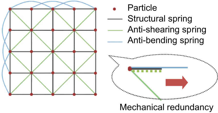
Particle–spring system.
The conventional system exhibits mechanical redundancy, with all types of springs collectively contributing to the tensile strength of the system when subjected to stretching, as depicted in the accompanying figure. As an underlying model for the virtual fabric, the system would have its tensile strength changed accordingly as the anti-bending spring coefficient being changed for stiffness, which restricts the ability for the fabric parameters to be set independently. Strength and stiffness are the two primary characteristics of clothing fabric that hold great importance. One of the major efforts of this study is to clearly separate and represent these two properties in the fabric model.
Let
where
Consider an important feature of real fabric, namely, anisotropy. This refers to the fact that the real fabrics have different values of mechanical properties in lengthwise (or warp-wise) and crosswise (or weft-wise), usually with high lengthwise strength and low crosswise strength. In each direction that transitions from lengthwise to crosswise, the mechanics of fabric are also different and are gradually varied, as demonstrated in Figure 2.
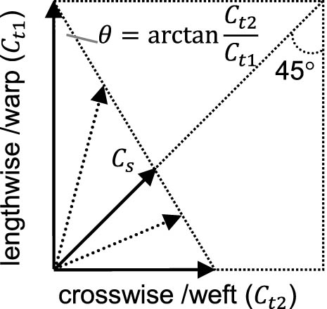
Mechanical anisotropy of fabric.
The anisotropy of real fabric demands for the model adopting different spring coefficients in the two directions, which are expressed in the following formulas:
More importantly, it suggests a certain relationship of restriction between the structural springs and the anti-shearing ones. Given that lengthwise and crosswise structural coefficients (
By substituting formulas (4) and (5) into formula (3), the following equations can be obtained:
Considering that
Formula (7) indicates that, the structural coefficients in the system can be figured out by solving a equation group given the system strength and stiffness. From another perspective, when the stiffness (
2.2 Deformation principles
The principles of virtual fabric deformation over time are elucidated in the following passages. At a specific moment
where
where
where
The above procedure of derivation manifests that the next position of any particle can be deduced from the state of the system at the current moment. For the initial moment (
Virtual fabric. (a) Fabric with a disc supporter. (b) Fabric with a sphere supporter. Note: A disc supporter is achieved through the process of vertical projection, specifically by projecting the particles that surpass the disc above it. While a sphere supporter is obtained by the radius projection, that is, to project the particles inside the sphere along the radius onto its surface.
2.3 Virtual cloth making
The actual process of cloth making is replicated by using virtual fabric and tailoring and sewing on it to create a dress. First, the fabric mesh is shaped according to the clothing pattern, with any excess particles and springs outside the pattern being eliminated to produce a virtual cut piece, as shown in Figure 4(a).
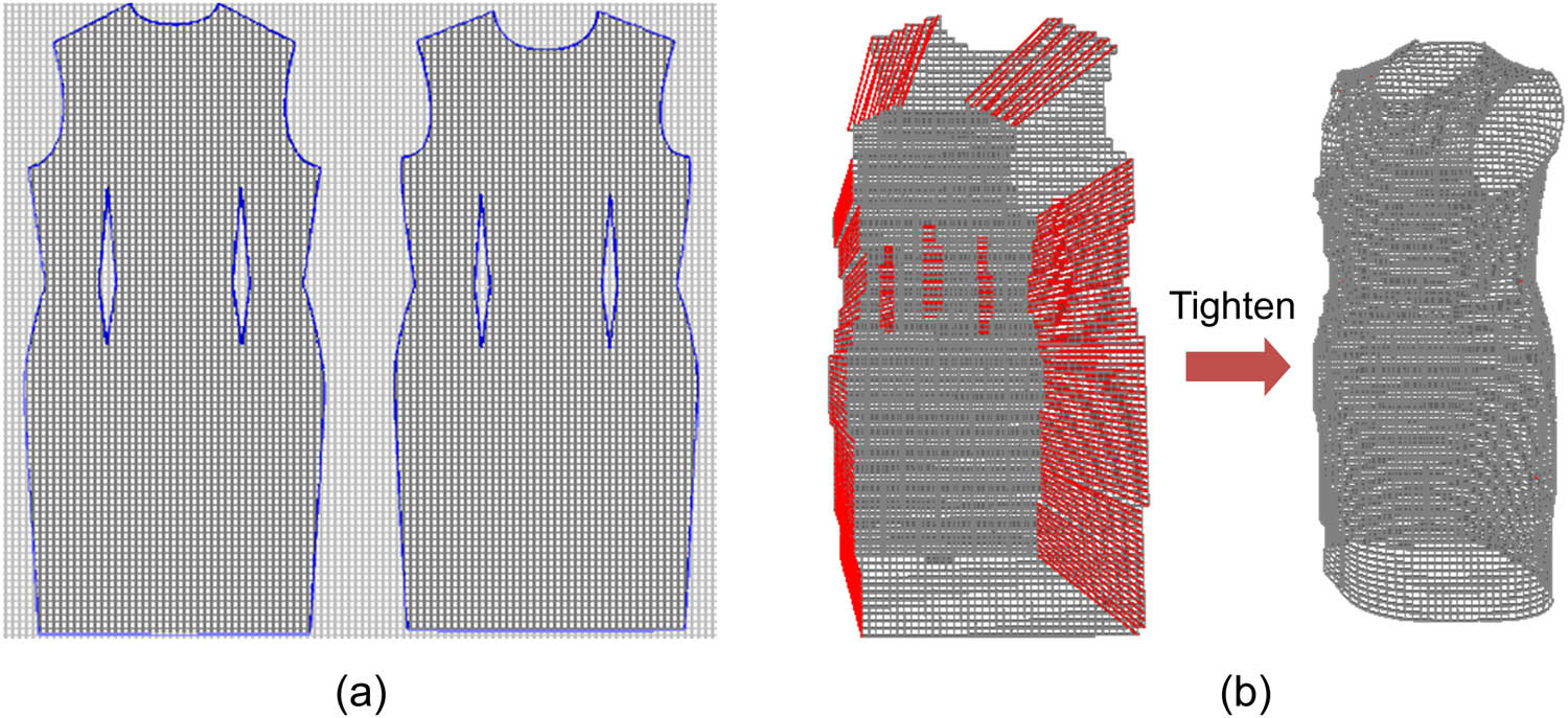
Virtual tailoring (a) and sewing (b).
Then, the stitches are arranged in order on the cut pieces where they are needed. The diagram shows stitches on the side lines, shoulder lines, chest darts, and back darts, as highlighted in red in Figure 4(b). The stitch points on the two pieces do not necessarily match up, so a linear mapping is adopted to carry out the pair-up in favor of an evenly stitched sewing line. Specifically, let
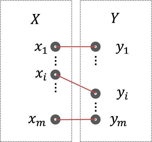
Linear pair-up of stitches. Note: The pair-up for sewing is employed connecting cloth pieces rather than imitating seam construction.
Given that they pair up in the start and the end (namely,
The equation allows for the calculation of
2.4 Body characterization
Due to the irregular geometry of the human body, directly assessing the interaction between virtual clothing and the extensive point cloud representation of the body requires excessive computational resources, making real-time response unfeasible. To make it lightweight, a 3D body usually requires simplification prior to use, as with the common “bounding box” approach which reduces the body into a combination of regular cuboids. In this study, a novel technique utilizing body slices is introduced to manage the contact more precisely while maintaining a low cost of computation.
The body’s point cloud is uniformly divided into segments along its vertical axis, and the polygons representing each segment are extracted. This process is illustrated in Figure 6(a). The extraction of the slice polygons is achieved using a rolling wheel mechanism, as depicted in Figure 6(b), with the chest slice as an example. The rolling wheel is designed to roll over the slice from the outside, collecting the points it comes into touch with to generate the corresponding polygon. The specific steps involved in this process are outlined as below.
Take the foremost point
Place the wheel on a horizontal line passing
Roll the wheel counterclockwise around the center point until a new point enters the scope of the wheel, collect the new point, and make it the new rolling center.
Repeat step (ⅲ) until the start point
Connect

Body characterization with slices. (a) 3D Body segmented into slices. (b) Rolling wheel for the slice polygon.
The wheel size being smaller than the gap between the body trunk and arms, the arms would get excluded from the slices, which is usually a desired outcome, as shown in the figure. If the size of the extracted slice is smaller than half of the point cloud’s size, it signifies that the rolling wheel is being applied on a lower limb. The point cloud is then evenly split into two parts on which the rolling wheel is performed separately to obtain the two sub-slices of the same height, which is necessary to manage the situation on the lower body.
It is obvious that the density of slices has a major influence on body characterization. Higher density of slices not only leads to a smoother body shape but also increased the amount of computation and time needed for the system to converge and therefore is a variable that requires balancing in practice.
With all the slice polygons being obtained, the virtual clothing’s contact with the 3D body is then simplified to its contact with the polygons, that is, to the judgment whether the particles of virtual clothing fall within the polygons.
2.5 Contact mechanism
As stated before, with the stitches being tightened, the virtual clothing tends to wrap the body from outside. In the deformation of the virtual clothing, the contact between clothing particles and body slices is continuously assessed to calculate the forces on the particles and in turn to determine the particle displacements according to the principles of fabric deformation, thereby guiding the virtual clothing to make further deformation.
The key of the contact mechanism is to decompose the force on the particles into two components: the normal direction and the normal plane, upon contact with the body slices, as demonstrated in Figure 7. The specific steps are as follows:
Determine whether the particle is touching the slice, that is, whether the particle falls within the polygon in geometry.
If yes, the particle is repositioned to point
Decompose the force (
Calculate the frictional force (
Recalculate the resultant force (
According to the deformation principles, calculate the next position of the particle, given its resultant force.
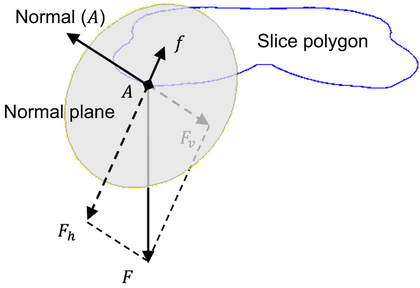
Contact mechanism.
The said frictional coefficient
Pressure distribution on the body.
The figure illustrates that the pressure exerted by clothing is primarily concentrated in specific areas of the human body, namely, the shoulder, chest, hip, and waist.
3 Experiments
Virtual clothing needs to apply to a three-dimensional body form which is based on the real human body. For body scanning, it is endeavored to carry out a portable and low-cost solution so as to get as close as possible to the actual conditions of the consumer end under virtual fitting. A portable depth camera is mounted on a support stem to capture the profiles of a mannequin, which stands upright on a simple turning platform with slightly stretched arms, as shown in Figure 9(a). The camera records the depth images of the body on different angles as the platform rotates, and these images are then joined together to bring out a complete 3D body form, as in Figure 9(b).
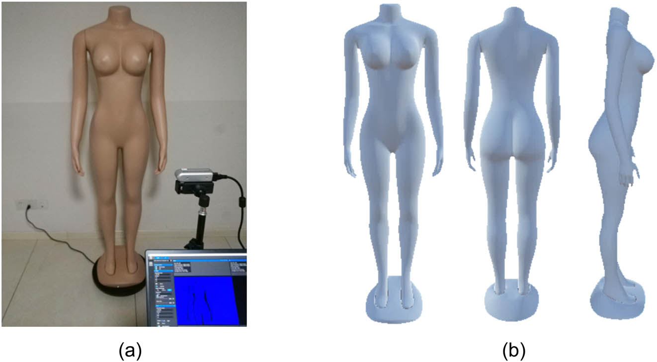
Three-dimensional body form. (a) Body scanning. (b) Body form. Note: (1) The depth camera utilized in this study is an Intel RealSense 435 device, and the processing of depth images takes the advantage of the Open3D pipelines. (2) The mannequin features the international standard size L, with a height of 170 cm, a bust size of 92 cm, and a hip size of 93 cm.
A paper pattern, as shown in Figure 10, is used to tailor the virtual fabric and sew it up to make a virtual dress, which has been elaborated with Figure 4. This pattern is also employed to make real clothes so as to bring a real peer to the virtual one. As in the figure, the pattern fits the body on the bust and hip sizes.
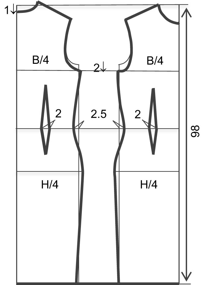
Pattern for both real and virtual clothes. Note: B (bust size) = 92 cm; H (hip size) = 93 cm.
To examine the accuracy of the calculated pressure on virtual clothing in comparison to the actual clothing pressure, the virtual fabric parameters are adjusted to align with the actual fabric properties. The correspondence between the real and virtual clothing is established as in Table 1.
Correspondence between the real fabric and the virtual one
| Real fabric | Virtual fabric | ||
|---|---|---|---|
| Breaking strength warp-wise | 630 N | Structural spring coefficient
|
630 |
| Breaking strength weft-wise | 406 N | Structural spring coefficient
|
406 |
| Bending stiffness warp-wise | 420 mN cm | Anti-bending spring coefficient
|
420 |
| Bending stiffness weft-wise | 305 mN cm | Anti-bending spring coefficient
|
305 |
| Surface frictional coefficient | 0.17 | Virtual frictional coefficient
|
0.17 |
Note: The real fabric is a woven fabric made of polyester. The breaking strength, bending stiffness, and surface friction are tested according to ISO 13934-1, ISO 9073-7, and ISO 8295, respectively.
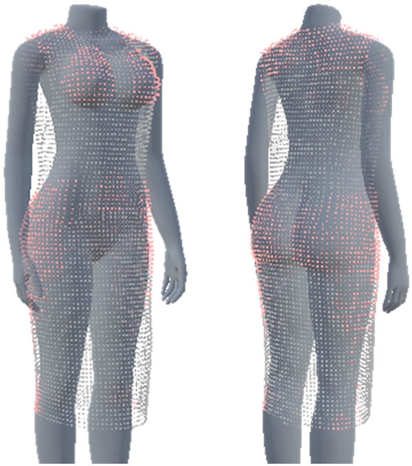
In order to obtain measurements, the mannequin is marked with designated points onto which thin-film pressure sensors are affixed, as shown in Figure 11(a). These measure points are determined considering the convex points of the body, which usually bear notable portions of clothing pressure, including bust height points (B1 and B2), shoulder height points (S1 and S2), back height points (K1 and K2), armpit points (A1 and A2), abdominal convex point (V), mid-waist back point (U), side-waist points (W1 and W2), hip height points (H1 and H2), mid-thigh front points (L1 and L2), and mid-thigh back points (M1 and M2). A dense version of slices is employed to segment the 3D body form so that these points can be spotted on the slices, as shown in Figure 11(b).
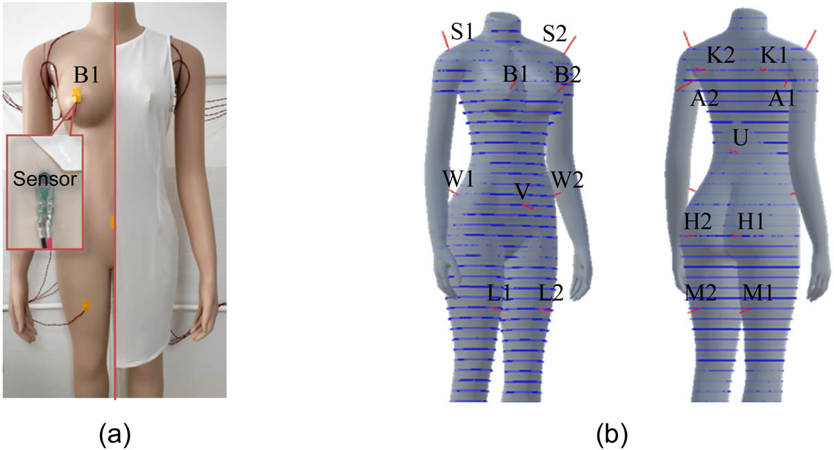
Pressure measuring and examining. (a) Measure points on the mannequin. (b) Corresponding locations in the slices. Note: FlexiForce A201-1 devices are used as the sensors measuring the actual pressure on the body. They are connected to an Arduino board which sends instant pressure data to a principal computer.
The actual pressure is read from the sensors, while the virtual pressure is computed as illustrated in Figure 7. To assess the reliability and resilience of the computed pressure under varying circumstances, the dress pattern is scaled to create clothing samples of the same style but varied sizes, as given in Table 2. These samples are then put on the mannequin, measured using pressure sensors, and compared to their virtual counterparts.
Different sizes of clothes
| Size | For height |
|---|---|
| Larger (XL) | 180 |
| Large (XL) | 175 |
| Fit (L) | 170 |
| Tight (M) | 165 |
| Tighter (S) | 160 |
4 Results
The effect of contact simulation with body slices is presented in Figure 12.
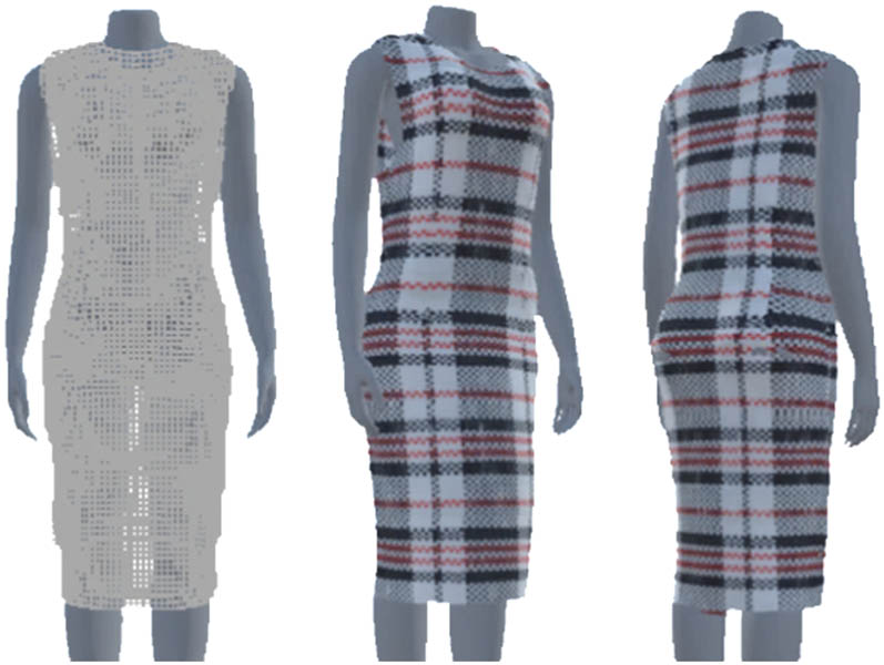
Effect of contact simulation with body slices (mesh and rendered). Note: The implementation is conducted on the Windows operating system taking advantage of OpenGL.
The pressure on the dressed body is obtained from the sensors, as given in Table 3.
Pressure obtained from the sensors
| S | B | K | A | V | U | W | H | L | M | |
|---|---|---|---|---|---|---|---|---|---|---|
| #1 | 11.783 | 8.018 | 1.939 | 1.232 | 0.348 | 0.038 | 2.463 | 4.338 | 0.026 | 0.083 |
| #2 | 11.094 | 6.825 | 2.232 | 1.011 | — | — | 2.037 | 3.550 | 0.021 | 0.100 |
| Variance (%) | 2.1 | 9.6 | 2.1 | 2.2 | 0 | 0 | 4.0 | 7.9 | 0.0 | 0.2 |
| Average | 11.438 | 7.421 | 2.085 | 1.122 | 0. 348 | 0. 038 | 2.250 | 3.944 | 0.024 | 0.092 |
As shown in Table 3, the variance on symmetric points (noted with #1 and #2) exhibits relatively low values, not exceeding 10%, which indicates credible results from the measurement. The body parts bearing the most pressure are the shoulder (S), chest (B), hips (H), and waist (W), in sequence. This aligns with the calculated pressure distribution in Figure 8. The actual pressure data are further investigated with comparison to the computed pressure values on the body slices, and their differences are demonstrated in Figure 13.
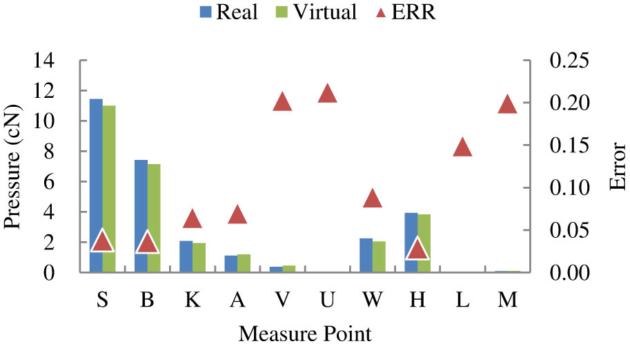
Comparation between the actual pressure and its virtual counterpart.
In general, the virtual pressure on the measure points averages an error of 11%, with the maximum 21%. Specifically, large errors (above the average) emerge on the measure points with a low pressure, such as on the abdominal convex point (V), the mid-waist back point (U), and the mid-thigh points (L and M). While the small errors (below the average) appear on the points with relatively high pressure, such as on the back height points (K), the armpit points (A), and the side-waist points (W). Especially on the bust height points (B), the shoulder height points (S) and the hip height points (H) which share most of the clothing pressure, the errors are as small as less than 5%.
Regarding varying sizes, the samples of different sizes given in Table 2 are employed to conduct validation tests. The results are presented in Table 4.
Performance on different sizes
| Size | Error (%) |
|---|---|
| Larger (XL) | 17.3 |
| Large (XL) | 13.5 |
| Fit (L) | 10.9 |
| Tight (M) | 9.7 |
| Tighter (S) | 9.2 |
It can be observed from the table that the computed pressure exhibits an average error of 10.9% under the fit size L. As the size increases, the error also increases, while it decreases when the size reduces. Conversely, under the tight sizes (S or XS), the error remains below 10%. This finding aligns with the observations depicted in Figure 11, which demonstrate that the virtual pressure performs better in body parts that bear a greater load. Consequently, it can be inferred that the calculated pressure derived from virtual clothing can provide valuable predictions for real clothing. This is particularly true for fit or tight sizes, where the predictions become even more precise.
5 Discussion
The simulated virtual clothing pressure computed from the cloth–body contact has shown a high level of agreement to the actual one, with its error being acceptable for the intended application scenarios. This addresses the gaps in the field of virtual fitting. In terms of visual effects, the proposed solution has effectively demonstrated the body support to clothes which can be viewed from Figure 12. This is similar to the effects that have been achieved with collision processes as introduced in the literature [19,20,21,22]. Furthermore, there are two factors related to visualization that can be used to better the display.
5.1 Fabric granularity
As aforesaid, the fabric model is grounded on the particle–spring system, with its precision subject to the mesh of the springs. In theory, a finer mesh would result in a more precise virtual fabric. However, aside from the increased computation amount, the smaller grain of mesh is observed, producing other effects in the contact simulation, as shown in Figure 14(a).
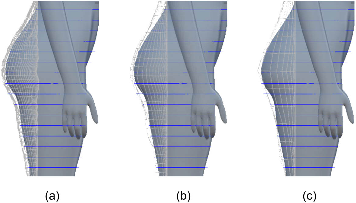
Virtual fit on the hip under various fabric granularities. (a) Small grain (1/4). (b) Moderate grain (1/2). (c) Large grain (1/1).
Since the body is represented by the slices, some fabric particles may fall into the gaps between the slices, especially when using an even smaller grain which could lead to a phenomenon known as the “collapse” effect, where the virtual clothing appears to collapse into the body. Provided the slice density is invariable, reducing the mesh grain to some extent can make the fabric fit the body better, while the fabric may penetrate the body if the mesh grain is reduced further. Therefore, the fabric granularity should be coordinated with the density of slices to achieve optimal results. Observations have revealed that the appropriate grain of fabric is approximately half of the interval between slices, as illustrated in Figure 14(b). In this situation, the fabric can smoothly cover the gaps between slices, neither causing the “collapse” effect nor creating a rough match with the body, as shown in Figure 14(c).
5.2 Stitch constraints
Virtual sewing is crucial for transforming a fabric mesh into three-dimensional clothing. This process, as previously explained, encompasses steps such as arranging the stitches on a cut piece, paring up the stitch points, and creating springs between these paired points. However, due to the stitches being kept by elastic springs, there is no assurance that the paired points will perfectly coincide in position under certain circumstances. Notably, when the virtual clothing experiences high tension, the stretched stitches tend to unravel, causing visual imperfections in rendering, as shown in Figure 15(a).
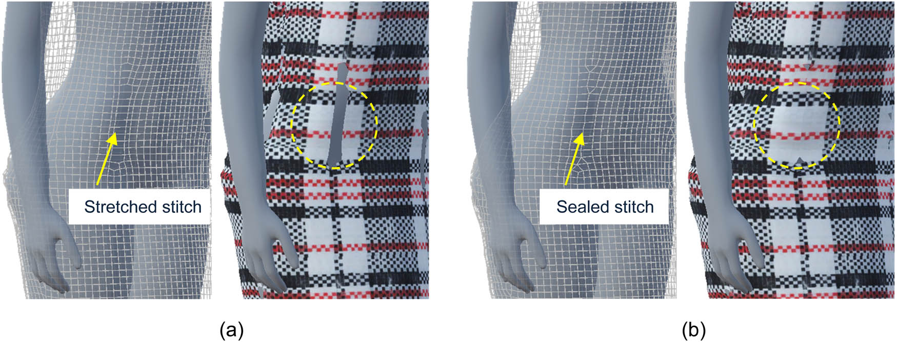
Improved rendering with constraints. (a) Visual defect and (b) defect removed.
In essence, the dynamics as well as deformability of virtual fabric benefits from an optimized version of the particle–spring system discussed previously. However, when it comes to virtual stitches that should not be deformed or elongated, the springs seem not to be well suitable. To address this issue, the springs on the stitches are improved by implementing constraints. A constraint conducts postprocessing after the associated spring completes its deformation in every moment by shrinking the spring from its two ends to the midpoint. This technique has proved to yield satisfactory results in rendering, as depicted in Figure 15(b).
It is important to note that the constraints are not based on principles of physics or mechanics but rather serve to enhance the visual effect. The inclusion of constraints in the model may distort the exerted forces on the fabric where stitches are applied. However, since the stitches make up a small portion of the springs on the fabric, this does not hinder the examination of force or pressure on the virtual clothing, so long as the stitches with constraints are skipped when determining measurement points.
6 Conclusions
This study addresses the issue of virtual fitting through the presentation of a comprehensive pipeline. The construction of the fabric model involves an enhanced version of a particle–spring system that reveals the implicit relationship between spring coefficients. By separating the fabric strength and stiffness, mechanical redundancy is eliminated, enabling the isolation of virtual fabric parameters. Simplified representations of the human body, known as body slices, are extracted from a mannequin. These body slices, along with the mechanical properties of the fabric and the resultant force on the human body, are used to calculate the deformation of the clothing fabric in real-time. This process creates a simulated contact between the clothing and the body. Importantly, the mechanical modeling employed in this simulation not only produces a realistic appearance of clothing on the human body but also generates calculated clothing pressure data that have been verified by experiments, demonstrating an error of 10.9% for the fit size and below 10% for smaller sizes. This foundation allows for sensible estimations and suggestions regarding pressure comfort in virtual try-on scenarios.
-
Funding information: This research was supported by the MOE Humanities and Social Sciences Foundation of China (23YJC760001) and Zhejiang Federation of Humanities and Social Sciences Circles research project (No. 75047).
-
Author contributions: Conceptualization: Chen Tao; Methodology: Chen Tao, Linlin Bai; Software: Chen Tao, Linlin Bai; Validation: Linlin Bai; Formal analysis: Linlin Bai; Investigation: Shuai Yu, Wei Yu; Resources: Shuai Yu, Wei Yu; Data Curation: Linlin Bai; Writing: Linlin Bai; Supervision: Chen Tao; Visualization: Junhong Chen; Funding acquisition: Linlin Bai.
-
Conflict of interest: The author(s) declared no potential conflicts of interest with respect to the research, authorship, and/or publication of this article.
-
Ethical approval: The conducted research is not related to either human or animal use.
-
Data availability statement: The datasets generated during and/or analyzed during the current study are available from the corresponding author on reasonable request.
References
[1] Kang, M. K., Lee, J. (2007). A real-time cloth draping simulation algorithm using conjugate harmonic functions. Computers & Graphics, 31(2), 271–279.10.1016/j.cag.2006.09.010Suche in Google Scholar
[2] Yi, S., Hongqu, Q. (2010). Simulation of fabric draping shape. Journal of Textile Research, 31(10), 34–39.Suche in Google Scholar
[3] Wang, H., O’Brien, J., Ramamoorthi, R. (2011). Data-driven elastic models for cloth: modeling and measurement. ACM Transactions on Graphics, 30(4), 1–12.10.1145/2010324.1964966Suche in Google Scholar
[4] Jiang, Y., Guo, R., Ma, F., Shi, J. (2019). Cloth simulation for Chinese traditional costumes. Multimedia Tools and Applications, 78(4), 5025–5050.10.1007/s11042-018-5983-8Suche in Google Scholar
[5] Sze, K. Y., Liu, X. H. (2007). Fabric drape simulation by solid-shell finite element method. Finite Elements in Analysis and Design, 43(11), 819–838.10.1016/j.finel.2007.05.007Suche in Google Scholar
[6] Xie, Q., Sze, K. Y., Zhou, Y. X. (2015). Drape simulation using solid-shell elements and adaptive mesh subdivision. Finite Elements in Analysis and Design, 106, 85–102.10.1016/j.finel.2015.08.001Suche in Google Scholar
[7] Han, M.-G., Chang, S.-H. (2021). Draping simulations of carbon/epoxy fabric prepregs using a non-orthogonal constitutive model considering bending behavior. Composites Part A: Applied Science and Manufacturing, 148, 106483.10.1016/j.compositesa.2021.106483Suche in Google Scholar
[8] Chen, Y., Wang, Q. J., Zhang, M. (2021). Accurate simulation of draped fabric sheets with nonlinear modeling. Textile Research Journal, 92(3–4), 539–560.10.1177/00405175211039573Suche in Google Scholar
[9] Mozafary, V., Payvandy, P. (2018). Introducing and optimizing a novel mesh for simulating knitted fabric. Journal of the Textile Institute, 109(2), 202–218.10.1080/00405000.2017.1335446Suche in Google Scholar
[10] Fitas, R., Hesseler, S., Wist, S., Greb, C. (2022). Kinematic draping simulation optimization of a composite B-pillar geometry using particle swarm optimization. Heliyon, 8(11), e11525.10.1016/j.heliyon.2022.e11525Suche in Google Scholar PubMed PubMed Central
[11] Bartol, K., Bojanić, D., Petković, T., Pribanić, T. (2021). A review of body measurement using 3D scanning. IEEE Access, 9, 67281–67301.10.1109/ACCESS.2021.3076595Suche in Google Scholar
[12] Pumarola, A., Sanchez-Riera, J., Choi, G. P. T., Sanfeliu, A., Moreno-Noguer, F. (2019). 3DPeople: Modeling the geometry of dressed humans. Paper presented at the Proceedings of the IEEE/CVF International Conference on Computer Vision (ICCV).10.1109/ICCV.2019.00233Suche in Google Scholar
[13] Lin, L., Zhang, M.-M., Pan, Z.-G., Kai-Jia, Q. I. U. (2015). Image-based detection and response of continuous fast collision between cloth and human body. Journal of Software, 26(S2), 1–7.Suche in Google Scholar
[14] Hui, Z., Zhen, L., Yanjie, C. (2018). Real-time collision detection method for fluid and cloth. Journal of Computer-Aided Design & Graphics, 30(4), 602–610.10.3724/SP.J.1089.2018.16528Suche in Google Scholar
[15] Jiang, L., Ye, J., Sun, L., Li, J. (2019). Transferring and fitting fixed-sized garments onto bodies of various dimensions and postures. Computer-Aided Design, 106, 30–42.10.1016/j.cad.2018.08.002Suche in Google Scholar
[16] Ait Mouhou, A., Saaidi, A., Ben Yakhlef, M., Abbad, K. (2022). 3D garment positioning using Hermite radial basis functions. Virtual Reality, 26(1), 295–322.10.1007/s10055-021-00566-7Suche in Google Scholar
[17] Xiao, B., Hu, Z., Liu, Z., Liu, L. (2024). A dynamic virtual try-on simulation framework for speed skating suits. The Journal of The Textile Institute, 115(5), 713–723.10.1080/00405000.2023.2201549Suche in Google Scholar
[18] Bridson, R., Fedkiw, R., Anderson, J. (2002). Robust treatment of collisions, contact and friction for cloth animation. ACM Transactions on Graphics, 21(3), 594–603.10.1145/566654.566623Suche in Google Scholar
[19] Selle, A., Su, J., Irving, G., Fedkiw, R. (2009). Robust high-resolution cloth using parallelism, history-based collisions, and accurate friction. IEEE Transactions on Visualization and Computer Graphics, 15(2), 339–350.10.1109/TVCG.2008.79Suche in Google Scholar PubMed PubMed Central
[20] Chen, Z., Feng, R., Wang, H. (2013). Modeling friction and air effects between cloth and deformable bodies. ACM Transactions on Graphics, 32(4), Article 88.10.1145/2461912.2461941Suche in Google Scholar
[21] Tang, M., Wang, T., Liu, Z., Tong, R., Manocha, D. (2018). I-cloth: incremental collision handling for GPU-based interactive cloth simulation. ACM Transactions on Graphics, 37(6), Article 204.10.1145/3272127.3275005Suche in Google Scholar
[22] Verschoor, M., Jalba, A. C. (2019). Efficient and accurate collision response for elastically deformable models. ACM Transactions on Graphics, 38(2), Article 17.10.1145/3209887Suche in Google Scholar
© 2024 by the authors, published by De Gruyter
This work is licensed under the Creative Commons Attribution 4.0 International License.
Artikel in diesem Heft
- Characterization of viscoelastic properties of yarn materials: Dynamic mechanical analysis in the transversal direction
- Analysis of omni-channel implementations that are preferred by consumers in clothing sector
- Structural modeling and analysis of three-dimensional cross-linked braided preforms
- An experimental study of mechanical properties and comfortability of knitted imitation woven shirt fabrics
- Technology integration to promote circular economy transformation of the garment industry: a systematic literature review
- Research on T-shirt-style design based on Kansei image using back-propagation neural networks
- Research on She nationality clothing recognition based on color feature fusion with PSO-SVM
- Accuracy prediction of wearable flexible smart gloves
- Preparation and performance of stainless steel fiber/Lyocell fiber-blended weft-knitted fabric
- Development of an emotional response model for hospital gown design using structural equation modeling
- Preparation and properties of stainless steel filament/pure cotton woven fabric
- Facemask comfort enhancement with graphene oxide from recovered carbon waste tyres
- Use of enzymatic processes in the tanning of leather materials
- Optical-related properties and characterization of some textile fibers using near-infrared spectroscopy
- Network modeling of aesthetic effect for Chinese Yue Opera costume simulation images
- Predicting consumers’ garment fit satisfactions by using machine learning
- Non-destructive identification of wool and cashmere fibers based on improved LDA using NIR spectroscopy
- Study on the relationship between structure and moisturizing performance of seamless knitted fabrics of protein fibers for autumn and winter
- Antibacterial and yellowing performances of sports underwear fabric with polyamide/silver ion polyurethane filaments
- Numerical and experimental analysis of ballistic performance in hybrid soft armours composed of para-aramid triaxial and biaxial woven fabrics
- Phonetic smart clothing design based on gender awareness education for preschoolers
- Determination of anthropometric measurements and their application in the development of clothing sizing systems for women in the regions of the Republic of Croatia
- Research on optimal design of pleated cheongsam based on Kano–HOQ–Pugh model
- Numerical investigation of weaving machine heald shaft new design using composite material to improve its performance
- Corrigendum to “Use of enzymatic processes in the tanning of leather materials”
- Shaping of thermal protective properties of basalt fabric-based composites by direct surface modification using magnetron sputtering technique
- Numerical modeling of the heat flow component of the composite developed on the basis of basalt fabric
- Weft insertion guideway design based on high-temperature superconducting levitation
- Ultrasonic-assisted alkali hydrolysis of polyethylene terephthalate fabric and its effect on the microstructure and dyeing properties of fibers
- Comparative study on physical properties of bio-based PA56 fibers and wearability of their fabrics
- Investigation of the bias tape roll change time efficiency in garment factories
- Analysis of foot 3D scans of boys from Polish population
- Optimization of garment sewing operation standard minute value prediction using an IPSO-BP neural network
- Influence of repeated switching of current through contacts made of electroconductive fabrics on their resistance
- Numerical calculation of air permeability of warp-knitted jacquard spacer shoe-upper materials based on CFD
- Compact Spinning with Different Fibre Types: An Experimental Investigation on Yarn Properties in the Condensing Zone with 3D-Printed Guiding Device
- Modeling of virtual clothing and its contact with the human body
- Advances in personalized modelling and virtual display of ethnic clothing for intelligent customization
- Investigation of weave influence on flame retardancy of jute fabrics
- Balloonless spinning spindle head shape optimisation
- Research on 3D simulation design and dynamic virtual display of clothing flexible body
- Turkish textile and clothing SMEs: Importance of organizational learning, digitalization, and internationalization
- Corrigendum To: “Washing characterization of compression socks”
- Study on the promotion multiple of blood flow velocity on human epidermal microcirculation of volcanic rock polymer fiber seamless knitted fabric
- Bending properties and numerical analysis of nonorthogonal woven composites
- Bringing the queen mother of the west to life: Digital reconstruction and analysis of Taoist Celestial Beings Worshiping mural’s apparel
- Modeling process for full forming sports underwear
- Retraction of: Ionic crosslinking of cotton
- An observational study of female body shape characteristics in multiracial Malaysia
- Study on theoretical model and actual deformation of weft-knitted transfer loop based on particle constraint
- Design and 3D simulation of weft-knitted jacquard plush fabrics
- An overview of technological challenges in implementing the digital product passport in the textile and clothing industry
- Understanding and addressing the water footprint in the textile sector: A review
- Determinants of location changes in the clothing industry in Poland
- Influence of cam profile errors in a modulator on the dynamic response of the heald frame
- Quantitative analysis of wool and cashmere fiber mixtures using NIR spectroscopy
- 3D simulation of double-needle bar warp-knitted clustered pile fabrics on DFS
- Finite element analysis of heat transfer behavior in glass fiber/metal composite materials under constant heat load
- Price estimation and visual evaluation of actual white fabrics used for dress shirts and their photographic images
- Effect of gluing garment materials with adhesive inserts on their multidirectional drape and bending rigidity
- Optimization analysis of carrier-track collision in braiding process
- Numerical and experimental analysis of the ballistic performance of soft bulletproof vests for women
- The antimicrobial potential of plant-based natural dyes for textile dyeing: A systematic review using prisma
- Influence of sewing parameters on the skin–fabric friction
- Validation by experimental study the relationship between fabric tensile strength and weave structures
- Optimization of fabric’s tensile strength and bagging deformation using surface response and finite element in stenter machine
- Analysis of lean manufacturing waste in the process flow of ready-to-wear garment production in Nigeria
- An optimization study on the sol–gel process to obtain multifunctional denim fabrics
- Drape test of fully formed knitted flared skirts based on 3D-printed human body posture
- Supplier selection models using fuzzy hybrid methods in the clothing textile industry