Characterization of viscoelastic properties of yarn materials: Dynamic mechanical analysis in the transversal direction
-
Karl Kopelmann
 ,
Mathis Bruns
,
Mathis Bruns

Abstract
Warp knitting creates very challenging dynamics due to its high production speeds. On the one hand, this makes it method of choice for many products in various fields. On the other hand, not all materials are suitable for such high productivity. With the current generation of machines being limited to only achieve their maximum speed of around 4,400 min−1 with highly elastic yarns, it is desired to gain a deeper insight into yarn behavior in such highly dynamic environments. Among other influences, resonance effects gain high significance as they may result in high loads on the used materials; therefore, yarn breakages interrupt the production and decrease the quality of the product. To extend the material choice, especially high-performance fibers, for high productivity, a deep understanding of the intrinsic properties of the yarn is required. In particular, the viscoelastic properties are of importance. This study proposes a method to determine these characteristics using the dynamic mechanical analysis method. For the purpose of finding the damping in the transversal direction to the yarn axis, the variant of free oscillation is chosen. For the trials, a high-speed camera is suspended above a testing rig. On this rig, a yarn sample is clamped and then displaced from its rest position. The resulting oscillation is recorded and later extracted from the video. From the decrement of the maxima of the amplitude and corresponding time intervals, the damping factor is determined. It decreases with higher initial deflection. Summarised the developed trial setup proved suitable for the determination of the viscoelastic properties in transversal direction.
1 Introduction
Warp knitting is a highly productive textile manufacturing process that simultaneously shapes all threads. It is favored for its versatility in creating a wide range of textile constructions [1]. The applications of warp knitting extend to various markets, including automotive manufacturing, shoe production, traditional garment production, and occasionally medical products. The most significant developments in this technology aim to enhance production efficiency, increase structural variability, and improve the quality of textiles.
The initial advancement focuses on enhancing textile machines by increasing their speeds and expanding their working widths [2,3,4]. However, during the processes involving continuous yarn supply and fabric withdrawal, there exists an unsteady behavior in the intermediate yarn withdrawal and traversing stages. It manifests as a highly dynamic and discontinuous loading scenario, which is further complicated by edge effects that create inhomogeneity across the processing width. The six intricate movements at the working position of the warp knitting process imposed on the yarn lead to simultaneous vibrations in both longitudinal and transverse directions. They lead to instances of extremely high yarn tension peaks that occur within milliseconds due to rapid yarn accelerations. Conversely, there are also phases in the process where yarn tension becomes low. Either case can result in yarn breakages or incorrect positioning and knit faults.
The local and temporal variability in yarn demand results in highly fluctuating yarn loads that can be amplified by resonance effects from the yarn guiding elements [5,6,7,8]. The vibration characteristics heavily depend on the material properties, such as fineness, yarn tension, stiffness, bending stiffness, and damping properties, as well as factors such as free path length and the forces exerted on the knitting and yarn guiding elements.
The natural vibrations of the moving elements of the machine are directly influenced by the machine speed (main shaft speed) and can lead to significant resonance amplifications and phase shifts between the knitting process and the yarn delivery. The first natural vibrations of the system occur at a machine speed of 1,800 rpm, making it challenging to process yarns with low elastic elongation. When the machine speed exceeds 3,000 rpm, the natural vibrations of the system become so prominent that only elastane yarns can be effectively processed [9,10].
Consequently, the use of high-performance fibers is limited. These yarns have limited elastic deformation capacity, with a breaking elongation below 15%. This can lead to yarn breakage or damage to the working elements of textile machines, particularly when the maximum tensile strength of high-performance yarns is too high.
Currently, processing these yarn materials on warp knitting machines is only feasible at very slow speeds. Achieving the desired processability often relies on a trial-and-error approach in practice [11]. Consequently, when issues arise with yarn guidance, the simplest and most effective solution is often to reduce speed, albeit at the expense of productivity, to attain the desired product quality.
Understanding the interactions and dependencies between different yarn materials, process parameters, and yarn guiding elements is crucial for achieving significant improvement and uniformity in yarn operation. However, the numerous influencing factors and intricate interplay of machine-specific and technological parameters make this task challenging. Therefore, having a solid understanding of the nonlinear material characteristics of the yarns being processed is essential.
Spun yarns exhibit distinct elastic–plastic behavior, while thermoplastic yarns display viscoelastic material properties [8,12,13,14]. Furthermore, when dealing with such yarns, the highly anisotropic nature adds complexity. Cyclically variable and vibration-loaded stresses occurring on textile machines result in hysteresis effects that affect both the process stability and the quality of the resulting textile surface. Additionally, there is limited knowledge about the short-term dynamics of yarns at high speeds. Current experimental investigations are conducted either online at few specific locations within the process or offline in the laboratory, such as high-speed tensile testing of filament yarns with relatively large break elongations (around 20%) [15,16,17].
However, there is a strong desire to comprehensively understand yarn characteristics [9,18,19]. With several hundred to a few thousand threads being processed simultaneously in warp knitting, the material properties alone impose high dynamic loads on mechanical parts and yarn guiding elements. Therefore, it is indispensable to use modeling and simulation techniques to capture the complexities of the process sequence.
Simplistic approaches are commonly observed when studying circular knitting and warp knitting processes. For instance, Koo [20] provided a description of yarn tension in the circular knitting process, considering variations in needle unit and shape. Duru et al. [7] conducted measurement-based investigations on the resistance of knitting needles in a circular knitting machine. de Vasconcelos et al. [21] examined the impact of yarn tension on stitch length in circular knitting machines using the mathematical analysis of the yarn path from the package to the feeder.
Liu and Miao [8] examined the analysis of yarn tension fluctuations in the chain warp knitting process. In their study, they performed a mathematical calculation of yarn requirements by considering the motion of laying bars and needles, assuming simple linear motion patterns. The yarn is described as linearly elastic and massless, similar to the approach taken by de Weldige [22].
None of the aforementioned research studies consider the damping properties of the yarn. Due to the anisotropic nature of most yarns, they will differ in longitudinal and transversal directions. A common method for their determination is the dynamic mechanical analysis (DMA) [23,24]. It provides valuable information about the moduli, damping, and other viscoelastic characteristics of polymers. In this method, an oscillatory force or strain is applied to the material, and the resulting vibration profile of the sample is measured. This process is typically repeated with various excitation frequencies and temperatures. The force applied during DMA can be either axial or torsional, depending on the specific experimental setup [25].
Two commonly used methods for DMA are the forced resonance and free resonance approaches. In the forced resonance method, the sample is securely clamped and stimulated with a constant sinusoidal force or strain function, while a sensor measures the corresponding response of the material. By analyzing the response of the material, the phase shift (δ) between the applied strain (ε) and the resulting stress (σ) can be determined using the following equations:
and
where t represents the time and ω represents the oscillation frequency. This enables the calculation of storage and loss moduli as the real and imaginary parts of Young’s modulus, respectively. The dissipation factor, which serves as a crucial measure of a material’s damping behavior, is defined as:
In the case of free resonance analysis, the samples are allowed to freely oscillate after an initial deflection and subsequent release [26]. The ensuing oscillation reflects the continuous exchange of energy between kinetic energy and potential energy. As there are additional internal forces and tensions within the material, the vibration gradually dissipates over time, leading to a decrease in amplitude. This evolution of the oscillation is recorded and forms the basis for calculating damping coefficients, which are dependent on the viscoelastic properties of the material.
The theory for the free resonance analysis is based on a damped oscillating system, consisting of a mass, a spring, and a damper. In the mathematical description of this model, it is assumed that the damper behaves proportionally to velocity. This approach can be easily described mathematically and accurately represents reality [27]. The force equilibrium of a one mass oscillator can be described as follows:
where m is the mass, b is the damping constant, c is the spring stiffness, and x is the displacement.
The system can furthermore be described as:
where ω 0 is the natural angular frequency of the undamped system and δ d is the damping factor. The combination of equations 4) and (5) leads to:
Therefore, a damped system can be described using the natural frequency and damping coefficient.
The natural frequency of vibration and the rate of decay of the vibration amplitude depend on the material. To generate a vibration in a system, an excitation is required. The equation of motion is extended to include a sinusoidal excitation, known as harmonic excitation, resulting in the following equation:
The decaying transient response is described by the term
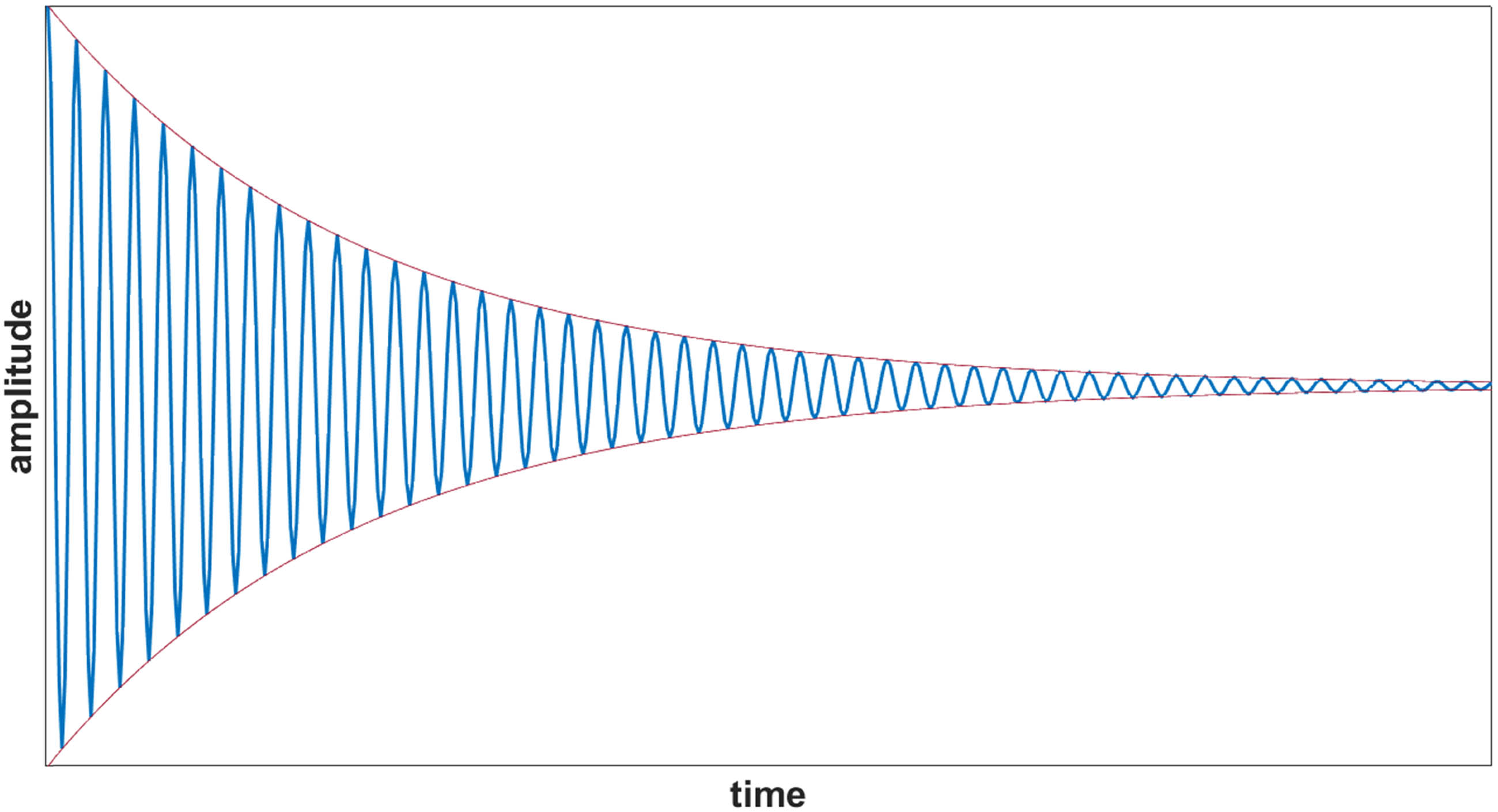
Exemplary course over time of a free oscillation.
Based on the ratio of two consecutive maxima of the recorded oscillation, it is possible to calculate the logarithmic decrement Λ. The evaluation takes place over all showing maxima from i to i + n. The resulting decrement is the overall average.
The logarithmic decrement is determinable from the product of the damping factor δ and the time t:
To determine the yarn damping, the amplitude needs to be measured as a function of time. From this, the logarithmic decrement (equation (9)) can be calculated, and ultimately, the damping factor (equation (10)) can be determined.
To summarize, the comprehensive understanding of the warp knitting process is challenging due to the large number of parameters involved and the complex behavior of yarn [28]. Currently, there is a lack of model-based descriptions for warp knitting processes that consider the dynamic parameters of yarn movement and the interaction with moving machine elements in contact with the nonlinear and elastic yarn [29]. An improved knowledge of the dynamic behavior of the yarn is an essential requirement for developing an effective simulation model. Due to the often anisotropic nature of yarns, the properties need to be determined in longitudinal and transversal directions. Longitudinal oscillations primarily arise from the tractive forces generated during stitch formation and take-up processes. Transverse oscillations result from yarn displacement during the laying phase and vibrations of the yarn guiding elements. A common method for this research is DMA, which needs to be adapted for the use with yarns. This study therefore focuses on applying it for the transversal damping characteristics of yarns.
2 Experimental
2.1 Materials
This study focuses on four different yarns selected to represent various use cases and material categories commonly processed on warp knitting machines. However, these yarns have limitations in terms of their achievable production speed due to their strength and limited strain capacity. One of the chosen materials is polyester, which plays a crucial role in numerous consumer products. For this study, two variants of polyester yarn are considered: a texturized variant (PES-tex) commonly used in fashion products and a high tenacity variant (HT-PES) more suitable for technical textiles. Additionally, the research also examines an aramid fiber as a representative of high-performance fiber materials known for their minimal strain capabilities and a cotton yarn, representing a staple fiber yarn material, as an additional yarn often used in the fashion industry that is very limited in the achievable production speeds (Table 1). The presented values are based on the product data sheets.
Overview over reviewed yarn materials
| Material | Manufacturer | Yarn linear density (dtex) | Yarn diameter (µm) | Young’s modulus (GPa) |
|---|---|---|---|---|
| HT-PES | PHP-fibers GmbH, Ger | 140 | 232 | 13 |
| PES-tex | TWD fibers, Ger | 179 | 185 | 1 |
| Cotton | Rütex GmbH, Ger | 200 | 183 | 6 |
| Aramid | Teijin Aramid BV, Nld | 225 | 438 | 74 |
2.2 Methods
To determine the damping characteristics in the transversal direction, the free resonance analysis method is chosen. The necessary loads for this trial are bending loads. The sample can oscillate freely and has just one degree of freedom. For the examination in the transversal direction, this means that a load perpendicular to the yarn axis is applied. The goal of the trial is to determine the influence of internal momentum and tension on steady conversion between potential and kinetic energy.
To measure the amplitude, a suitable setup (Figure 2) is developed. It consists of a metal frame that holds the ends of the yarn in a horizontal orientation. In the middle between the two holding points, a pin is located whose displacement from yarn sample axis is adjustable. When a sample is tested, it is placed on the frame and its ends are fixed, while the sample is free of tension. The sample length is 60 mm. Then, the middle is bended by pulling it over the pin. Then, the yarn is released from the pin and oscillates till it comes to rest. The whole motion is captured by a high-speed camera that observes the behavior from above. The camera is a FASTCAM SA-X2 by Photron, capable of recording with a maximum frame rate of 106 s−1 or a maximum resolution of 1,024 by 1,024 pixels. For each material, different initial displacements are tested corresponding to a certain pre-strain. The camera uses a frame rate of 10,000 s−1 and is manually triggered.
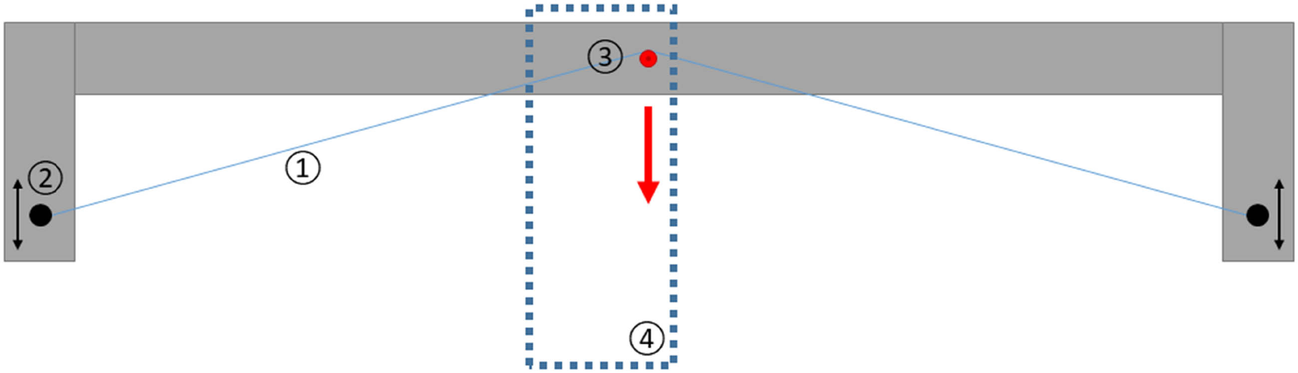
Setup for free oscillation trials with (1) yarn sample, (2) adjustable yarn fixation, (3) release pin, and (4) high-speed camera field of view.
The materials are tested with different initial strain values. Based on these values, the initial displacement is calculated using equation (11):
where x 0 is the initial displacement, l 0 is the clamping length, and ε is the initial strain.
Based on this, the values shown in Table 2 are chosen for the trials.
Calculated initial displacement based on the desired strain and the sample length
| Strain (%) | 0.5 | 1 | 2 | 3 | 4 | 5 |
|---|---|---|---|---|---|---|
| Displacement (mm) | 30 | 43 | 60 | 74 | 86 | 96 |
Through an optimized lighting setup (Figure 3), the yarn samples are clearly distinguishable from the background. Using MatLab, a threshold is applied to separate sample and background into two defined regions. In the following, the path of the sample is tracked along one vertical pixel row allowing for a time-dependent plotting of the amplitude. Next, the maxima are located, and in the following, Λ (equation (9)) and δ d (equation (10)) can be calculated.
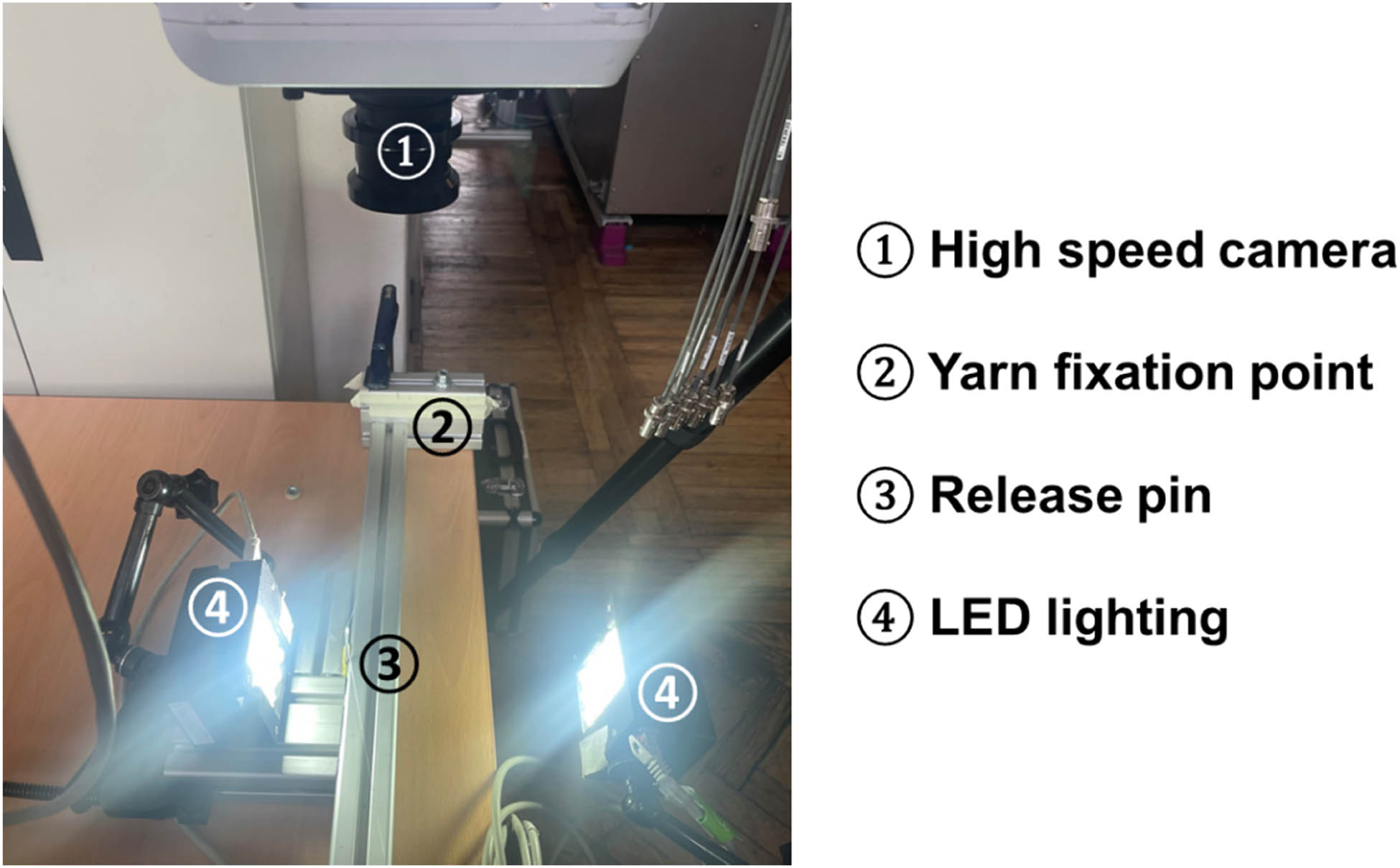
Test setup with suitable positioning of lighting elements for good differentiation between yarn and background.
3 Results and discussion
The recording of the yarn oscillation showed a rapid damping of the oscillation evoked by the displacement. Figure 4 shows a few shots of the course of the free oscillation of an Aramid sample. The applied picture editing methods lead to black white captures guaranteeing a high contrast between the background (black) and the sample (white).
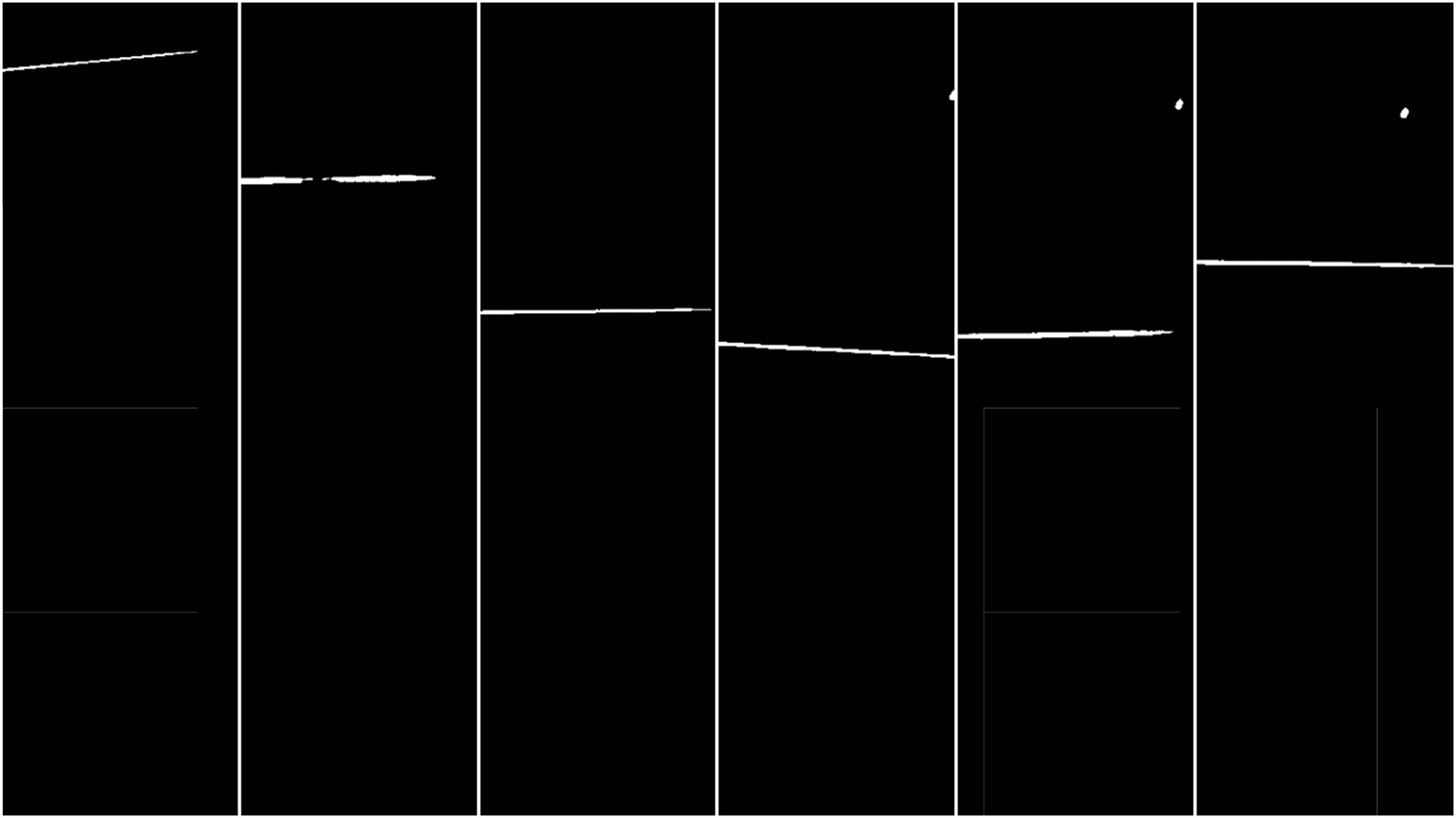
Oscillation of an Aramid yarn sample with an initial displacement of 30 mm shortly after release. Picture(s) cropped and diverted into black and white using the applied threshold.
The small spot in the upper-right corner is the pin used for the release of the yarn and therefore neglected in the evaluation. The course of the white line representing the yarn sample is tracked along one vertical pixel row.
Once in oscillating state, the center of oscillation is determined and defined by setting it as the 0 mm mark. The conversion factor from pixels to mm was determined by taking a picture of a linear scale on the finalized setup with the high-speed camera. For the time data, a linear vector was created based on the capturing rate of 10,000 s−1. The local peaks and the corresponding time values were determined and used for the calculation of the decrement and the damping factor in the following. The damping factor is expressed by the mean value for each displacement.
As seen in Figure 5, the recorded tracks of the yarn oscillations show obvious differences between the materials. For clarity, the graph only shows the extremes among the material choice of this research, presenting PES-tex as the lower-end and Aramid as the higher-end material. With the Aramid sample, the amplitude of vibration lowered much faster than the oscillation in the PES-tex sample. However, the PES-tex shows an almost sinusoidal course, and the progress of Aramid appears to have some irregularities. The reflection of the oscillation on the clamping point is considered as the reason for this.
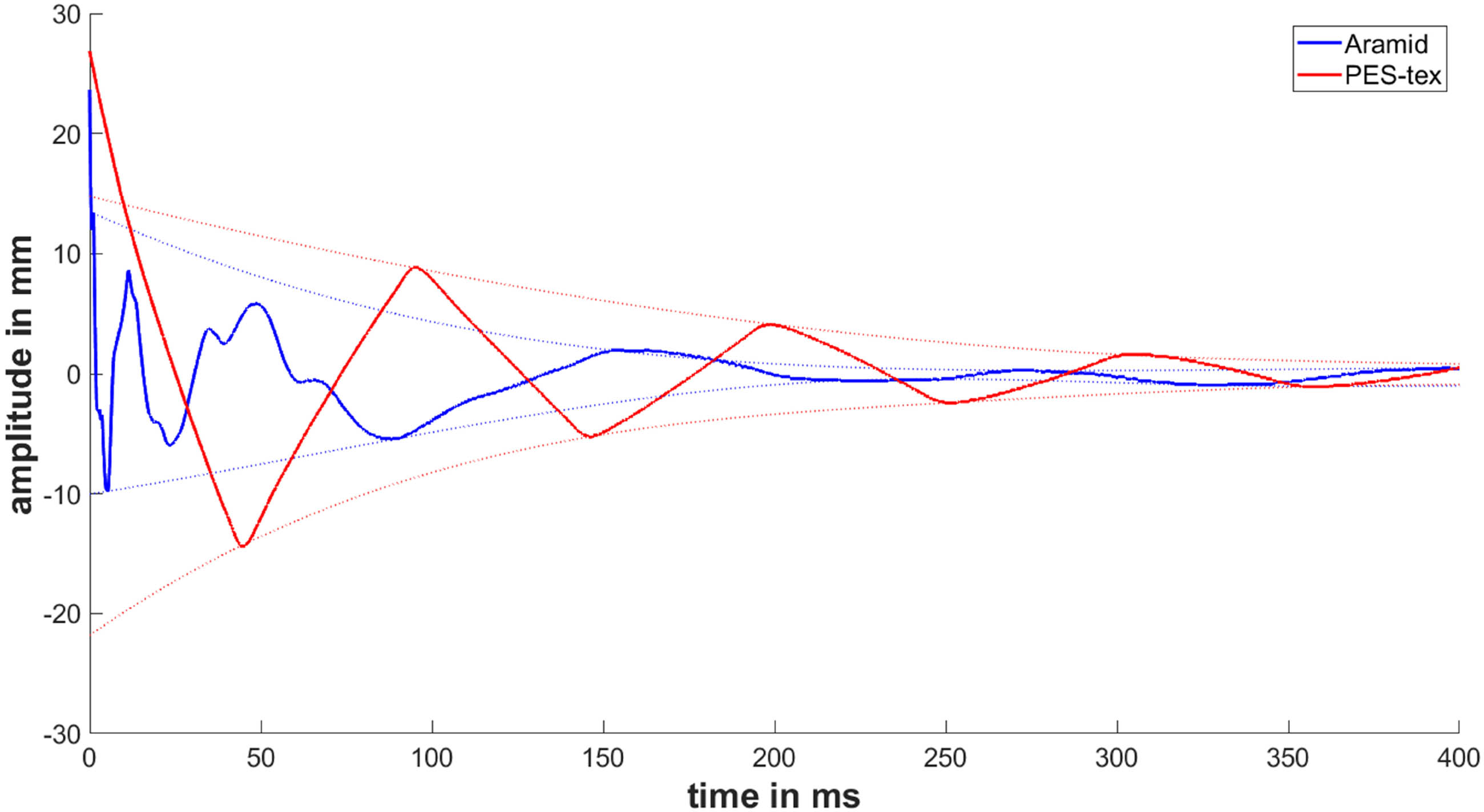
Comparison of the oscillation of Aramid and PES-tex with a displacement of 0.5%.
Despite the faster decrease of the amplitude observed for Aramid (Figure 5), the damping factor of PES-tex is higher. This is due to the lower oscillation period of the Aramid. As PES-tex also possesses higher elasticity than Aramid, the calculated damping factor appears to be reasonable. An overview of the results is given in Figure 6 and Table 3.
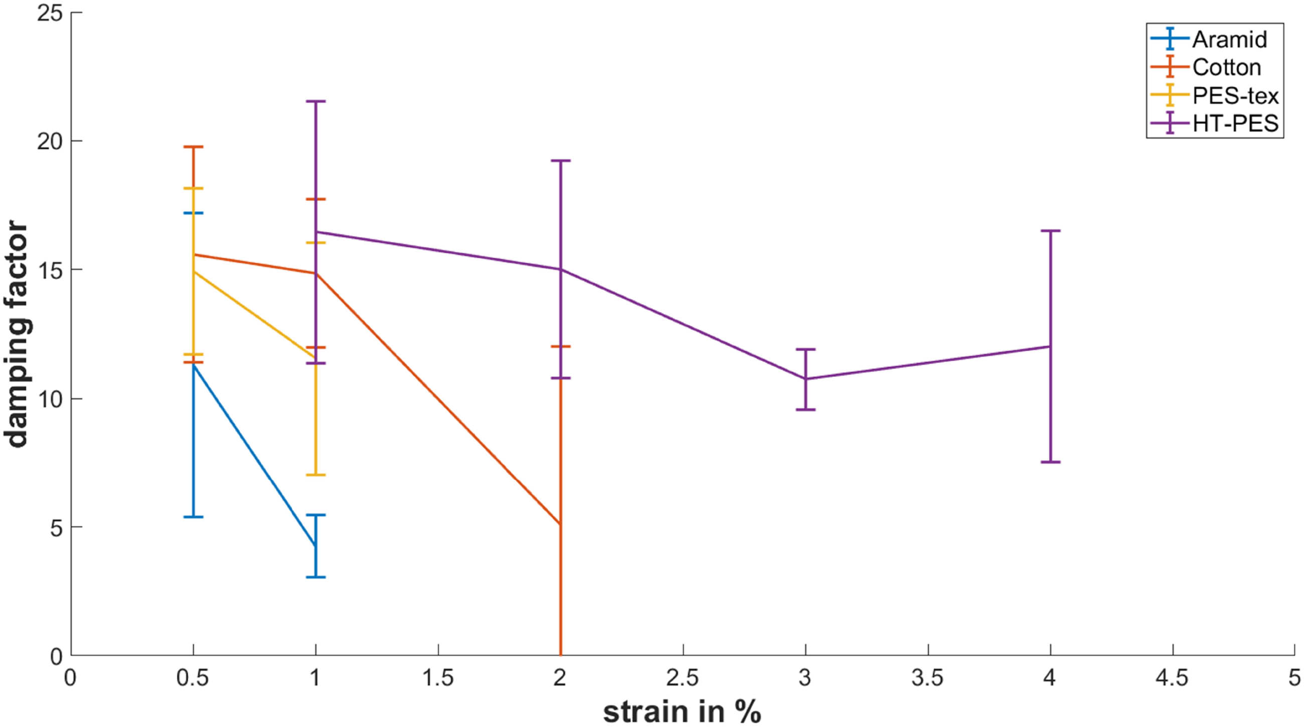
Comparison of the damping factor for the tested material and different strains represented by the mean values and the corresponding 95% confidence intervals.
Overview over results for the damping factor
| Damping factor | ||||||||
|---|---|---|---|---|---|---|---|---|
| Strain (%) | Aramid | Cotton | PES-tex | PES-HT | ||||
| Mean | SD | Mean | SD | Mean | SD | Mean | SD | |
| 0.5 | 11.3 | 6.04 | 15.6 | 3.70 | 14.9 | 6.17 | — | — |
| 1 | 4.2 | 1.23 | 14.9 | 3.86 | 11.5 | 5.15 | 16.5 | 6.35 |
| 2 | — | — | — | — | — | — | 15.0 | 4.31 |
| 3 | — | — | –– | — | — | — | 10.7 | 1.68 |
| 4 | — | — | — | — | — | — | 12.0 | 3.96 |
As apparent from the results, not all displacements and therefore strain values were suitable for all materials. The majority of the yarn could not be tested at strains higher than 2%. Further increase lead to too high frictional forces on the release pin. Therefore, single fibers of the multifilaments stuck on the way to the pin tip and prevented a simultaneous release of the whole yarn (Figure 7).
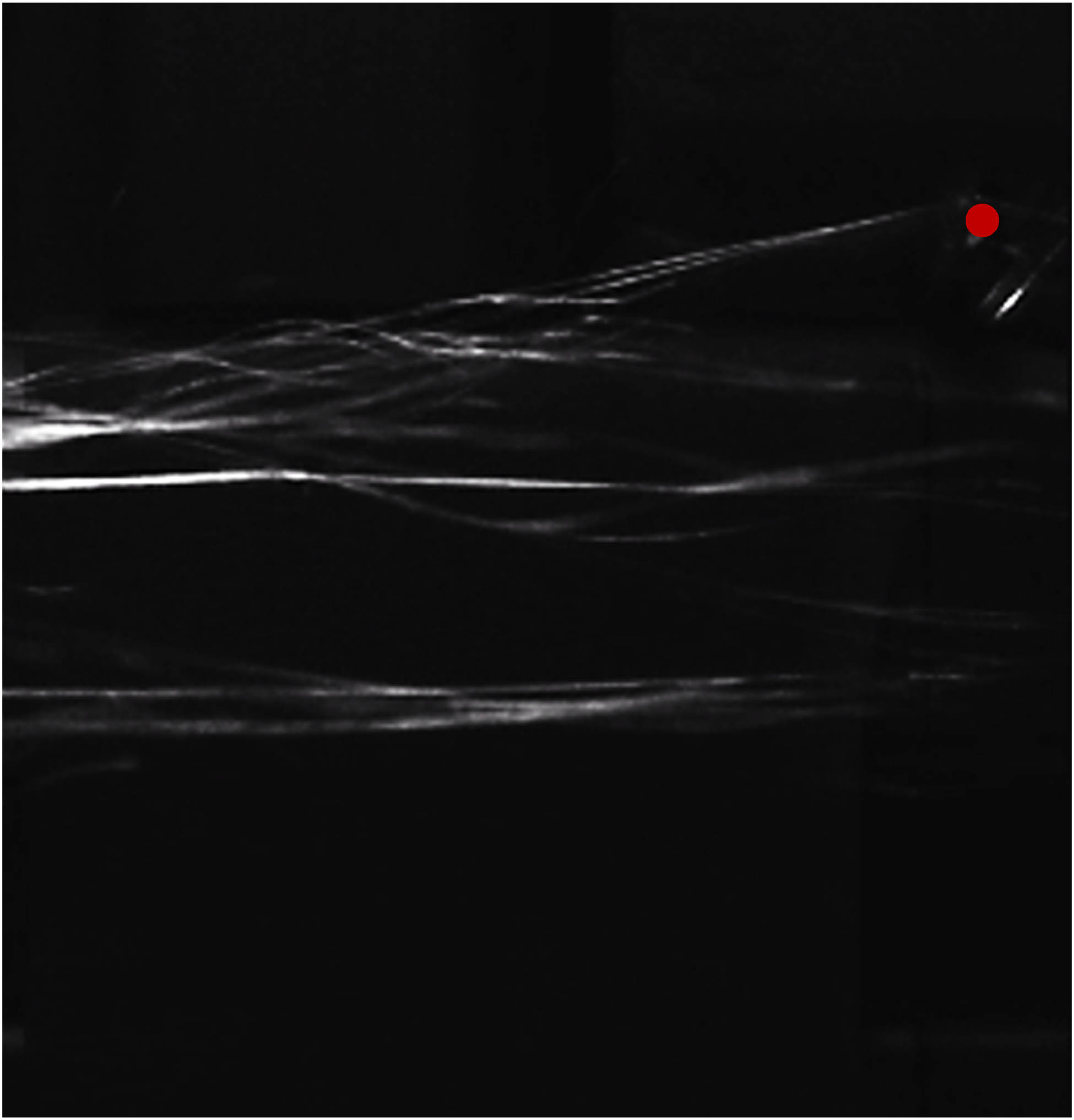
Picture of an unsuccessful yarn release due to too high yarn tension and friction on the pin (red dot): the filaments of the Aramid yarn are spread and do not move uniformly.
4 Conclusions
This study proposed a method for the evaluation of viscoelastic properties of the yarn in the transversal direction through a free oscillation method. The derived setup mainly relies on yarn oscillation recordings with a high-speed camera. From these captures, the movement tracks of a single tracking point along the yarn axis were determined and used to create a time-based diagram. Within this graph, the maxima were located and used for the calculation of the decrement and the corresponding damping factor.
The results showed the expected behavior with the low strength and more elastic materials having higher damping factors and the high-performance fibers presenting low damping factors. Higher elasticity also allowed for a higher range of test parameters. Combined with other results that also analyzed yarn properties in respect of its behavior during the warp knitting process, these findings allow a further refinement of a yarn-based process simulation.
Viscoelastic properties are especially relevant for the evaluation of the influence of the warp knitting binding on the yarn dynamics as the main reason for movements in the transversal direction is swinging motion of the laying bar, which is pattern dependent. While the yarn dynamics are considered to be mainly influenced by yarn demand during the stitch formation process with the desire to increase to production speeds, the transversal dynamics are gaining more weight in the consideration of the simulation and design.
While this study already covers two major groups of yarns used in the industry, the material variety can be further extended in the future. Another main influence in dynamic mechanic analysis is the temperature. It was not considered in this research, as the warp knitting process is usually not exposed to highly varying temperatures. Nevertheless, this can be further investigated if the results are considered for different purposes. Overall, the test setup appeared sufficient for the desired measurements and it was possible to gain reasonable results for different yarn materials. These materials allow for a further refinement of yarn simulation models and the process simulation in warp knitting.
Acknowledgements
The DFG research project CH 174/44-1 was supported by the Deutsche Forschungsgemeinschaft (DFG, German Research Foundation). The financial support was gratefully acknowledged.
-
Funding information: The Article Processing Charges (APC) were funded by the joint publication funds of the TU Dresden, including Carl Gustav Carus Faculty of Medicine, and the SLUB Dresden as well as the Open Access Publication Funding of the DFG.
-
Conflict of interest: Authors state no conflict of interest.
-
Data availability statement: Data are available from the authors upon reasonable request.
References
[1] KARL MAYER Textilmaschinenfabrik GmbH. Anwendungen | KARL MAYER. https://www.karlmayer.com/de/anwendungen/ (Retrieved 12 Mai 2023).Search in Google Scholar
[2] Bornschein, S. Luftwebmaschine A1 - Lindauer DORNIER GmbH. https://www.lindauerdornier.com/de/webmaschinen/luftwebmaschine-a1/ (Retrieved 8 Mai 2023).Search in Google Scholar
[3] Anonymous. Historie - Terrot. https://www.terrot.de/de/unternehmen/historie.aspx (Retrieved 8 Mai 2023).Search in Google Scholar
[4] Anonymous (2008). Copcentra 2K-TWIN 2-in-1 Hochleistungskettenwirkautomat/2-in-1 High-Performance Tricot Machine. LIBA Maschinenfabrik GmbH, Naila.Search in Google Scholar
[5] Denninger, D., Berger, M. (2014). Mechanischer Fadenlängenausgleich zur optimalen Handhabung von Flechtmaterialien. Conference of Technische Universität Chemnitz, 14. Chemnitzer Textiltechnik Tagung, Chemnitz. Search in Google Scholar
[6] Pohlen, V., Schnabel, A., Neumann, F., Gries, T. (2012). Optimisation of the warp yarn tension on a warp knitting machine. Autex Research Journal, 2, 29–33.10.2478/v10304-012-0006-8Search in Google Scholar
[7] Duru, S. C., Candan, C., Mugan, A. (2015). Effect of yarn, machine and knitting process parameters on the dynamics of the circular knitting needle. Textile Research Journal, 6, 568–589.10.1177/0040517514547216Search in Google Scholar
[8] Liu, X., Miao, X. (2017). Analysis of yarn tension based on yarn demand variation on a tricot knitting machine. Textile Research Journal, 4, 487–497.10.1177/0040517516632473Search in Google Scholar
[9] Ünal, A. (2004). Analyse und Simulation des Fadenlängenausgleichs an Kettenwirkmaschinen für die optimale Konstruktion von Fadenspanneinrichtungen. W.E.B (Dresden).Search in Google Scholar
[10] Märtin, J. (2012). Analyse, Simulation und Weiterentwicklung des Materialtransportes in Hochleistungskettenwirkautomaten zur Steigerung der technologischen Leistungsparameter. ITM (Dresden).Search in Google Scholar
[11] Su, L., Meng, Z., Sun, Y., Ge, X. (2018). Reliability-based optimization design of the latch needle mechanism in double-needle warp knitting machine. Journal of the Brazilian Society of Mechanical Sciences and Engineering, 4, 205.10.1007/s40430-018-1134-4Search in Google Scholar
[12] Bunsell, A. R. (2009). Handbook of tensile properties of textile and technical fibres. Woodhead Publishing (Oxford).10.1533/9781845696801Search in Google Scholar
[13] Zubair, M., Neckar, B., Eldeeb, M., Baig, G. A. (2017). Tensile behavior of staple fiber yarns, part IV: experimental verification of predicted stress–strain curves. Journal of the Textile Institute, 8, 1291–1296.10.1080/00405000.2016.1243195Search in Google Scholar
[14] Dietz, W. (2015). Polyester fiber spinning analyzed with multimode Phan Thien-Tanner model. Journal of Non-Newtonian Fluid Mechanics, 217, 37–48.10.1016/j.jnnfm.2015.01.008Search in Google Scholar
[15] Finckh, H. (2011). Hochgeschwindigkeits-Zugprüfung an technischen Garnen. Conference of Zwick/Roell Textil Symposium, Ulm.Search in Google Scholar
[16] Weiß-Quasdorf, M., Lützkendorf, M., Gombic, L., Hauspurg, C. (2012). Versagensverhalten dynamisch belasteter Hochleistungsgarne bei Hochgeschwindig-keitsbelastung. Conference of 51st Man-Made Fibers Congress, Dornbirn.Search in Google Scholar
[17] Bahners, T., Schloßer, U., Gutmann, J. (2011). Untersuchung des visko-elastischen Verhaltens technischer Garne bei Kurzzeitbean-spruchungen mit hoher Dehnungsgeschwindigkeit (AiF 15925 BG). Deutsches Textilforschungszentrum Nord-West e.V. (Krefeld). Conference of AUTEX2019 – 19th World Textile Conference on Textiles at the Crossroads, Ghent.Search in Google Scholar
[18] Franz, C., Häntzsche, E., Hoffmann, G., Nocke, A., Cherif, C. (2019). Simulation of the stich formation process and modelling of the yarn movement in high performance tricot knitting machines.10.21825/autex.63828Search in Google Scholar
[19] Metzkes, K., Schmidt, R., Märtin, J., Hoffmann, G., Cherif, C. (2013). Simulation of the yarn transportation dynamics in a warp knitting machine. Textile Research Journal, 12, 1251–1262.10.1177/0040517512470197Search in Google Scholar
[20] Koo, Y.-S. (2004). Yarn tension variation on the needle during the knitting process. Textile Research Journal, 4, 314–317.10.1177/004051750407400405Search in Google Scholar
[21] de Vasconcelos, F. B., Marcicano, J. P. P., Sanches, R. A. (2015). Influence of yarn tension variations before the positive feed on the characteristics of knitted fabrics. Textile Research Journal, 17, 1864–1871.10.1177/0040517515576327Search in Google Scholar
[22] de Weldige, E. (1996). Prozesssimulation der Kettfadenzugkräfte in Webmaschinentypen. (Aachen), PhD thesis, RWTH Aachen.Search in Google Scholar
[23] Ceravolo, R., de Marchi, A., Pinotti, E., Surace, C., Zanotti Fragonara, L. (2017). A new testing machine for the dynamic characterization of high strength low damping fiber materials. Experimental Mechanics, 1, 65–74.10.1007/s11340-016-0208-4Search in Google Scholar
[24] Ballou, J. W., Smith, J. C. (1949). Dynamic measurements of polymer physical properties. Journal of Applied Physics, 6, 493–502.10.1063/1.1698416Search in Google Scholar
[25] Tsai, C. L., Daniel, I. M., Lou, J. J. (1993). Measurement of longitudinal shear modulus of single fibers by means of a torsional pendulum. International SAMPE Symposium and Exhibition (Proceedings), 38, 1861–1868.Search in Google Scholar
[26] Magnus, K., Popp, K. (2002). Schwingungen. Vieweg + Teubner Verlag (Wiesbaden).10.1007/978-3-663-01339-6Search in Google Scholar
[27] Lorsch, P. (2016). Methodik für eine hochfrequente Ermüdungsprüfung an Faserverbundwerkstoffen. (Braunschweig), PhD thesis, DLR Braunschweig.Search in Google Scholar
[28] Veit, D. (2012). Simulation in textile technology. Elsevier Science, Oxford.10.1533/9780857097088Search in Google Scholar
[29] Goktepe, O., Harlock, S. C. (2002). Three-dimensional computer modeling of warp knitted structures. Textile Research Journal, 3, 266–272.10.1177/004051750207200314Search in Google Scholar
© 2024 by the authors, published by De Gruyter
This work is licensed under the Creative Commons Attribution 4.0 International License.
Articles in the same Issue
- Characterization of viscoelastic properties of yarn materials: Dynamic mechanical analysis in the transversal direction
- Analysis of omni-channel implementations that are preferred by consumers in clothing sector
- Structural modeling and analysis of three-dimensional cross-linked braided preforms
- An experimental study of mechanical properties and comfortability of knitted imitation woven shirt fabrics
- Technology integration to promote circular economy transformation of the garment industry: a systematic literature review
- Research on T-shirt-style design based on Kansei image using back-propagation neural networks
- Research on She nationality clothing recognition based on color feature fusion with PSO-SVM
- Accuracy prediction of wearable flexible smart gloves
- Preparation and performance of stainless steel fiber/Lyocell fiber-blended weft-knitted fabric
- Development of an emotional response model for hospital gown design using structural equation modeling
- Preparation and properties of stainless steel filament/pure cotton woven fabric
- Facemask comfort enhancement with graphene oxide from recovered carbon waste tyres
- Use of enzymatic processes in the tanning of leather materials
- Optical-related properties and characterization of some textile fibers using near-infrared spectroscopy
- Network modeling of aesthetic effect for Chinese Yue Opera costume simulation images
- Predicting consumers’ garment fit satisfactions by using machine learning
- Non-destructive identification of wool and cashmere fibers based on improved LDA using NIR spectroscopy
- Study on the relationship between structure and moisturizing performance of seamless knitted fabrics of protein fibers for autumn and winter
- Antibacterial and yellowing performances of sports underwear fabric with polyamide/silver ion polyurethane filaments
- Numerical and experimental analysis of ballistic performance in hybrid soft armours composed of para-aramid triaxial and biaxial woven fabrics
- Phonetic smart clothing design based on gender awareness education for preschoolers
- Determination of anthropometric measurements and their application in the development of clothing sizing systems for women in the regions of the Republic of Croatia
- Research on optimal design of pleated cheongsam based on Kano–HOQ–Pugh model
- Numerical investigation of weaving machine heald shaft new design using composite material to improve its performance
- Corrigendum to “Use of enzymatic processes in the tanning of leather materials”
- Shaping of thermal protective properties of basalt fabric-based composites by direct surface modification using magnetron sputtering technique
- Numerical modeling of the heat flow component of the composite developed on the basis of basalt fabric
- Weft insertion guideway design based on high-temperature superconducting levitation
- Ultrasonic-assisted alkali hydrolysis of polyethylene terephthalate fabric and its effect on the microstructure and dyeing properties of fibers
- Comparative study on physical properties of bio-based PA56 fibers and wearability of their fabrics
- Investigation of the bias tape roll change time efficiency in garment factories
- Analysis of foot 3D scans of boys from Polish population
- Optimization of garment sewing operation standard minute value prediction using an IPSO-BP neural network
- Influence of repeated switching of current through contacts made of electroconductive fabrics on their resistance
- Numerical calculation of air permeability of warp-knitted jacquard spacer shoe-upper materials based on CFD
- Compact Spinning with Different Fibre Types: An Experimental Investigation on Yarn Properties in the Condensing Zone with 3D-Printed Guiding Device
- Modeling of virtual clothing and its contact with the human body
- Advances in personalized modelling and virtual display of ethnic clothing for intelligent customization
- Investigation of weave influence on flame retardancy of jute fabrics
- Balloonless spinning spindle head shape optimisation
- Research on 3D simulation design and dynamic virtual display of clothing flexible body
- Turkish textile and clothing SMEs: Importance of organizational learning, digitalization, and internationalization
- Corrigendum To: “Washing characterization of compression socks”
- Study on the promotion multiple of blood flow velocity on human epidermal microcirculation of volcanic rock polymer fiber seamless knitted fabric
- Bending properties and numerical analysis of nonorthogonal woven composites
- Bringing the queen mother of the west to life: Digital reconstruction and analysis of Taoist Celestial Beings Worshiping mural’s apparel
- Modeling process for full forming sports underwear
- Retraction of: Ionic crosslinking of cotton
- An observational study of female body shape characteristics in multiracial Malaysia
- Study on theoretical model and actual deformation of weft-knitted transfer loop based on particle constraint
- Design and 3D simulation of weft-knitted jacquard plush fabrics
- An overview of technological challenges in implementing the digital product passport in the textile and clothing industry
- Understanding and addressing the water footprint in the textile sector: A review
- Determinants of location changes in the clothing industry in Poland
- Influence of cam profile errors in a modulator on the dynamic response of the heald frame
- Quantitative analysis of wool and cashmere fiber mixtures using NIR spectroscopy
- 3D simulation of double-needle bar warp-knitted clustered pile fabrics on DFS
- Finite element analysis of heat transfer behavior in glass fiber/metal composite materials under constant heat load
- Price estimation and visual evaluation of actual white fabrics used for dress shirts and their photographic images
- Effect of gluing garment materials with adhesive inserts on their multidirectional drape and bending rigidity
- Optimization analysis of carrier-track collision in braiding process
- Numerical and experimental analysis of the ballistic performance of soft bulletproof vests for women
- The antimicrobial potential of plant-based natural dyes for textile dyeing: A systematic review using prisma
- Influence of sewing parameters on the skin–fabric friction
- Validation by experimental study the relationship between fabric tensile strength and weave structures
- Optimization of fabric’s tensile strength and bagging deformation using surface response and finite element in stenter machine
- Analysis of lean manufacturing waste in the process flow of ready-to-wear garment production in Nigeria
- An optimization study on the sol–gel process to obtain multifunctional denim fabrics
- Drape test of fully formed knitted flared skirts based on 3D-printed human body posture
- Supplier selection models using fuzzy hybrid methods in the clothing textile industry