Structural modeling and analysis of three-dimensional cross-linked braided preforms
-
Chengjie Du
 ,
Zhuo Meng
,
Jianhan Hong
,
Zhuo Meng
,
Jianhan Hong

Abstract
Rotary braiding is widely used in the preparation of high-performance fiber composites. However, neither conventional rotary two-dimensional braiding nor rotary three-dimensional braiding can prepare three-dimensional preforms with low porosity and dense surface yarns. This article designs a three-dimensional cross-linked braiding equipment, describes the mechanism of carrier motion of three-dimensional cross-linked braiding, and obtains a numerical model of three-dimensional cross-linked braided preforms by establishing the spatial coordinate system of the braided chassis and using cubic B-spline curve fitting. The reasons for the large difference between the numerical model of preform and the real fabric are analyzed, and an optimization algorithm is proposed to make the fabric compact by gathering the yarn to the center of the fabric. The experimental samples are braided on a three-dimensional cross-linked braiding machine, and the reliability of the optimization algorithm is verified by comparing the yarn coordinates of the experimental samples with those of the optimized numerical model. The accurate establishment of the geometric model of the preform provides a solid foundation for carrying out the prediction of the mechanical properties of composite materials.
1 Introduction
Rotary braiding has the advantages of higher braiding efficiency and longer braiding machine life than four-step braiding, and it is possible to prepare preforms with bending and variable cross-section by regulating the braiding angle. When the braided yarn is a high-performance fiber such as carbon fiber, the composite structure can be widely used in aerospace, military, rail transportation, and other fields [1,2].
The rotary two-dimensional braiding process is relatively mature. Although the fiber volume fraction of the fabric is high, it is a single-layer structure, so the interlayer adhesion is poor and the application is narrow. There is a large amount of research focusing on three-dimensional braiding processes.
Yordan [3,4] introduced a three-dimensional braiding machine with an equal number of horn gears in the horizontal and vertical directions. The yarn in the outer layer of the preform will pass through the middle layer into the inner layer to form a three-dimensional body structure, but there is a strict correspondence relationship between the number of horn gears and the number of horn-gear slots in this process, and the preform has a low fiber volume fraction and a large porosity. Midani et al. [5] concluded that delamination is a basic failure mode of thick braided structural parts, and the problem of interlayer delamination can be effectively solved by using three-dimensional braiding techniques. Chengjie et al. [6] developed a mathematical model of carrier arrangement based on a multilayer interlocking braiding and verified the carrier arrangement for I-section and C-section fabrics. Shao et al. [7] designed a braiding process for T-section fabrics on a three-dimensional rotary braiding machine and determined the carrier arrangement solution based on the braided chassis track and carrier motion law. Glessner and Kyosev [8] investigated the technique of braiding preforms with bifurcated structures, and structural parts with such characteristics have common applications in the medical field.
In the reinforcement of the composite material, the structure of the preform plays a crucial role in the mechanical properties of the composite material, and the current structural models of the preform are mainly divided into mechanical equivalent model, unit cell geometrical model, and yarn geometrical model [9]. Sun and Sun [10] calculated the mechanical properties such as tensile stiffness, shear stiffness, and Poisson’s ratio of three-dimensional rectangular braided composites by the volume-average-compliance method, and found that the topological model greatly underestimated the tensile stiffness and shear stiffness, and the yarns inside 3D braided preform were curvy, which was opposite to the straight-yarn assumption of the topological model. Hao et al. [11] analyzed the carrier motion law of three-dimensional four-directional cylindrical braiding, established the cell geometrical model with different braiding angles and fiber volume fractions, and investigated the effects of braiding angles and fiber volume fractions on the elastic constants of composites from the theoretical and numerical analysis. Bilisik [12] investigated the effect of braiding patterns on the structure of preform unit cells. Yordan [13] proposed an algorithm that can independently control the blocks to model the variable cross-section preforms. Kamble and Behera [14] established a three-dimensional four-directional preform geometrical model for predicting the fabric fiber volume fraction based on the relationship between the surface braiding angle and the internal braiding angle of the fabric. Zhou et al. [15] proposed a preform modeling method based on a multilayer interlocking braiding process and used OpenGL to visualize 3D fabric. Gideon et al. [16] established three-unit cell models for cylindrical braiding and determined the damage limits of the three-unit cell models in axial pressurization experiments by means of simulations and experiments. Zhang et al. [17] developed a parametric representative volume element model composed of dry fibers and matrix for predicting the tensile modulus of three-dimensional four-directional braided composites by integrating Matlab software and Abaqus software.
Although the fiber volume fraction of two-dimensional braided fabrics is high, it is a single-layer structure, and the adhesion between layers of three-dimensional braided fabrics is strong, but the porosity is high. This article aims to design a braiding method that has the advantages of both two-dimensional braiding and three-dimensional braiding, and seek an optimization algorithm to construct an accurate preform structural model, so as to provide a solid foundation for the subsequent use of preform geometric models to simulate and predict the structural and mechanical properties of the fabrics and thus reduce the experimental cost.
2 Carrier arrangement of three-dimensional cross-linked braiding
Conventional rotary two-dimensional braiding prepares fabrics with small thicknesses, which are often increased by means of stacking. As a result, they are prone to delamination when subjected to large bending or torsional loads, as shown in Figure 1(a). We envisage that the interlayer bonding properties of the preform can be enhanced by locally placing cross-linked yarns between the fabric layers without reducing the fabric fiber volume fraction, as shown in Figure 1(b).

Schematic diagram of enhanced interlayer bonding. (a) Delamination. (b) Interlayer cross-linked yarn.
The mechanical parts of the three-dimensional cross-linked braiding machine are mainly composed of braided chassis, 4-slot horn gears, 5-slot horn gears, 6-slot horn gears, gears, carriers, etc., as shown in Figure 2. The preforms have two layers, inside and outside, and the braided chassis and the blocks fixed on it form an “∞” shaped track. Driven by horn gears, half of the carriers on the braiding machine move forward along the track and the other half move backward along the track.

Three-dimensional cross-linked braiding machine. (a) Three-dimensional cross-linked braiding machine model. (b) Part of three-dimensional cross-linked braiding machine.
Figure 3 shows the initial position of the carriers of the three-dimensional cross-linked braiding machine. There are 5 rings and 120 columns of horn gears, the first and fifth rings are made up of 4-slot horn gears, and the carriers are arranged in the way of “1F1E.” The second and fourth rings are made up of 5-slot horn gears, and the third ring is made up of 6-slot horn gears. The horn gears of the second to fourth rings are installed every three columns. The horn gears in columns 1 and 120 are connected at the beginning and end to form a closed loop. Let the radius of the 4-slot horn gear be R. To ensure the alignment of adjacent horn gear slots, the radius of the 5-slot horn gear is 1.25R, and the radius of the 6-slot horn gear is 1.5R.

Initial position of the carriers of the three-dimensional cross-linked braiding machine.
As shown in Figure 3, the first ring has two kinds of carriers, red and blue, moving on the red and blue tracks, respectively. The fifth ring has two kinds of carriers, green and purple, moving on the green and purple tracks, respectively. The three-dimensional cross-linked braiding machine has two working states, independent and cross-linked, and the working state is switched by setting the vary-trajectory mechanism at the intersection of the 4-slot horn gear and 5-slot horn gear, i.e., A, B, C, and D in Figure 3. The braiding machine does not stop when the carrier changes trajectory. When in the independent state, carriers of the first ring and the fifth ring move on their respective tracks, and the inner and outer layers of the preform are separated. The principle of cross-linking is that the positions of a specific blue carrier on ring 1 and a specific purple carrier on ring 5 are exchanged, and the rest carriers move on their respective tracks. Set blue No. 2, blue No. 6, purple No. 3, and purple No. 7 as cross-linked carriers, and the carrier movement of one horn gear slot is recorded as one step. Carriers No. 2 and No. 6 in blue can enter the black track of the second ring by means of the vary-trajectory mechanism, and carriers No. 3 and No. 7 in purple can enter the black track of the fourth ring by means of the vary-trajectory mechanism. After several steps of carrier movement, the blue No. 2 and blue No. 6 carriers are located on the purple track, while the purple No. 3 and purple No. 7 carriers are located on the blue track, and the inner and outer layers of preforms are cross-linked. Figure 4 shows the carrier trajectories in independent and cross-linked working states.
Carrier trajectories of the three-dimensional cross-linked braiding. (a) Carrier trajectories in the independent state. (b) Carrier trajectories in cross-linked state.
Figure 5 shows the three-dimensional cross-linked braiding process. Set the vary-trajectory mechanism to switch the braiding machine to the cross-linked state, and the carriers move two steps. Switch the braiding machine to the independent state and the carriers move another seven steps. The blue No. 2 and blue No. 6 carriers are located on the purple track, and the purple No. 3 and purple No. 7 carriers are located on the blue track. The three-dimensional cross-linked braiding is completed.
Three-dimensional cross-linked braiding process. (a) Carrier movement 0 step (cross-linked state). (b) Carrier movement two steps (independent state). (c) Carrier movement four steps (independent state). (d) Carrier movement nine steps (independent state).
3 Structural modeling of three-dimensional cross-linked braided preforms
3.1 Establishment of the spatial coordinate system of the braided chassis
The numerical model of the preforms can help to analyze and predict the mechanical properties of the composites. The construction of the numerical model of the three-dimensional cross-linked braided preforms must follow its braiding process. Let the radius of the 4-slot horn gear be R, then the radius of the 5-slot horn gear is 1.25R, the radius of the 6-slot horn gear is 1.5R, and the distance between ring 1 and ring 5 is 10R. If the spatial coordinate system of the braided chassis shown in Figure 3 is established, the distance between the inner and outer layers of the preform is far, which does not match the reality.
Figure 6 shows the equivalent diagram of the trajectories of carriers in the cross-linked state. Although the blue track intersects with the purple track, the blue No. 2 and the purple No. 7 carriers do not appear in the second and fourth rings at the same time, respectively, so the yarn trajectories in the preform do not intersect in the second and fourth rings. The blue No. 2 carrier enters ring 2 from right to left and then leaves ring 4 from left to right. The blue track of ring 3 is on the right of the purple track, so the trajectory of the blue No. 2 yarn in the preform is located to the right of the purple No. 7 yarn, and they do not intersect.

Equivalent diagram of the trajectories of carriers in the cross-linked state.
According to the aforementioned analysis, the second and the fourth rings can be removed, and the 6-slot horn gear of the third ring can be replaced by the 4-slot horn gear, so as to obtain the coordinate diagram of the braided chassis as shown in Figure 7, and the side length of each grid is a.

Coordinate diagram of the braided chassis.
3.2 Spatial trajectory of the yarns
Figure 6 shows that the position of each carrier can be represented by coordinates, and the sampling point coordinates of the red yarns are as follows:
The sampling point coordinates of the green yarns are as follows:
The sampling point coordinates of the blue yarns in the independent state are as follows:
The sampling point coordinates of the purple yarns in the independent state are as follows:
To ensure that the cross-linked yarn has enough length to clearly identify its distribution in the preform, set blue No. 4, blue No. 8, purple No. 5, and purple No. 9 (not shown in Figure 7) as cross-linked carriers. The coordinates of the sampling points for the 18 steps of the blue No. 4 carrier movement are as follows:
The coordinates of the sampling points for the 18 steps of the blue No. 8 carrier movement are as follows:
The coordinates of the sampling points for the 18 steps of the purple No. 5 carrier movement are as follows:
The coordinates of the sampling points for the 18 steps of the purple No. 9 carrier movement are as follows:
The Z coordinates of the yarn sampling points are as follows:
where t is the number of steps, and set the horn gear to rotate one slot as one step. h is the traction length of the preform after one step of horn gear rotation.
Combining the actual process parameters, the coordinates of the sampling points of the blue No. 4, blue No. 8, purple No. 5, and purple No. 9 carriers shown in Figure 8(a) are obtained by substituting a = 5.5 and h = 8 into equations (5)–(9), and the yarn trajectories shown in Figure 8(b) are obtained by connecting the adjacent sampling points of each carrier with short line segments.

Yarn trajectories of the blue No. 4, blue No. 8, purple No. 5 and purple No. 9 carriers. (a) Yarn sampling points. (b) Connect adjacent sampling points with short line segments.
Combining equations (1)–(9), the yarn trajectories shown in Figure 9 are obtained by using Matlab software to connect the sampling points of the remaining yarns. The two adjacent sampling points of the yarn are connected by short segments, and the short segments before and after each sampling point will form an angle, which does not match the actual smooth yarn.
Yarn trajectories of the three-dimensional cross-linked braiding.
3.3 Yarn trajectory B-spline curve fitting
The yarn trajectories obtained by connecting sampling points with short line segments are not smooth, so curve fitting is required. Bezier curves and B-spline curves are common fitting tools in computer-aided design and computer graphics. Bezier curve has two disadvantages: (i) the number of polygon vertices used for fitting is related to the degree of curves, so the degree of curves cannot be adjusted arbitrarily; (ii) the basis function of Bezier curve is not zero in the interval (0, 1), so adjusting any control point curve will change, which is not conducive to local fine-tuning. B-spline curve not only inherits the advantages of Bezier curve, which is simple and easy to use, but also can modify the local characteristics of the curve as needed, and the degree of polynomial is low, so they are widely used.
The general expression of the B-spline curve is
where P i (i = 0,1,…,n) is the ith control point of the input n + 1 control points. B i,k (u) is k-degree B-spline basis function and is defined by the Cox-de Boor recursive formula as follows:
where u k is the node vector U = {u 0, u 1,…, u n+k }.
From equation (10), when k = 2, the basis function B i,k (u) is
From equation (10), when k = 3, the basis function B i,k (u) is
From equation (10), when k = 4, the basis function B i,k (u) is expressed as follows:
where C(i), D(i), E, and F are intermediate variables, and their values are given as follows:
To meet the fitting accuracy and not to consume too much computational resources, the yarn trajectories are fitted with cubic B-spline curves, and the first four consecutive sampling points of the carrier are used as the control points of the fitted curve, and the node vector is set as follows:
By substituting the coordinates of the sampling points, equations (13) and (14) into equation (10), we obtain the first section of the yarn fitted curve. The second section of the fitted curve uses the fourth to seventh sampling points as control points, and so on to calculate the fitted curve of the whole yarn as shown in Figure 10(a). The fitted curves for all yarns are shown in Figure 9(b). Let the yarn cross-section be circular, and take the yarn trajectory shown in Figure 10(b) as the centerline, and scan it with a circle of radius r = 2.5 mm to obtain the numerical model of the preform as shown in Figure 10(c).
Cubic B-spline curve fitting numerical model of the preform. (a) Fitted trajectory of cross-linked yarn. (b) Fitted trajectories of all yarns. (c) Numerical model of the preform.
From Figure 10(c), it can be seen that the red and blue yarns form the outer braided layer, and the green and purple yarns form the inner braided layer, which are only distributed in their respective braided layers. Black yarn 1, black yarn 2, yellow yarn 1, and yellow yarn 2 represent blue No. 4, blue No. 8, purple No. 5, and purple No. 9 carriers in Figure 7, respectively. It can be seen that these four yarns cross-link the outer and inner braided layers.
3.4 Numerical model optimization of the preform
The spatial trajectory of the yarn is smoother than the folding trajectory after cubic B-spline curve fitting, but it can be seen from the numerical model of the preform in Figure 10 that the gaps between yarns are large. In contrast, real braided fabrics have small gaps as the yarns touch each other during the tightening process, so the preforms fitted by the cubic B-spline curves differ significantly from the real fabrics. To ensure that the numerical model of the preform is more realistic for predicting the mechanical properties of the composite by simulation, the fabric model needs to be optimized to reduce the gaps between the yarns to make the overall structure compact.
The distances between the carriers are large as can be seen from the coordinate diagram of the braided chassis in Figure 7, and the sampling points of the preform are determined according to the coordinates of the carriers on the braided chassis, which is the root cause of the large gaps in the numerical model. Figure 11 shows a schematic diagram of the yarn-tightening trend. Although the carrier will only move along the track on the braided chassis during the braiding process, the yarn at the traction end will tend to tighten toward the center S of the braided chassis until all yarns contact each other.

Yarn tightening trends.
In the numerical simulation of preforms, the relationship between yarns has three cases: spacing, contact, and interference. Contact is the ideal state, and also the goal of preform numerical model optimization. Figure 12 shows the motion vector diagram of yarn spacing and interference states. Set the yarn cross-section diameter as d and divide the yarn movement into several steps, with a small distance w for each step. For the case of yarn spacing, the cross-section center A of yarn 1 moves along
For the case of yarn interference, the cross-section center A of yarn 1 close to point S moves along
In the structural optimization of the preform, due to the large number of yarns and complex calculations, it is difficult to achieve the ideal state of
The numerical model of the preform shown in Figure 10(c) is divided equally into n slices along the Z-axis direction, and the center coordinates of the ith (0 < i ≤ 15) blue yarn cross-section in the ath (0 < a ≤ n) slice are (x ai , y ai ), the center coordinates of the jth (0 < j ≤16) red yarn cross-section are (x aj , y aj ), the center coordinates of the kth (0 < k ≤15) purple yarn cross-section are (x ak , y ak ), and the center coordinates of the lth (0 < l ≤ 16) green yarn cross-section are (x al , y al ). The steps for optimizing the numerical model of the preform are as follows:
Calculate the distances between the centers of any two yarn cross-sections in the first slice and put the results into an array M. If there is an element less than d in M, mark the two yarn cross-section centers corresponding to this element as A and B, respectively.
Repeat steps 1–3 to optimize the remaining n − 1 slices.

Motion vector diagram of yarn spacing and interference states. (a) Spacing. (b) Interference.
According to the aforementioned steps, the trajectories of all yarns are obtained, and then scan them with a circle of radius r = 2.5 mm to obtain the optimized numerical model of the preform, as shown in Figure 13. Compared with the model before optimization shown in Figure 10(c), the distance between the inner and outer layers and the gaps between yarns of the optimized model are smaller, so the preform is more compact and more realistic.

Optimized numerical model of the preform.
4 Experimental verification
To further investigate the accuracy of the numerical model of the preform, experiments are conducted on the three-dimensional cross-linked braiding machine shown in Figure 14, and the main technical parameters of the braiding machine are presented in Table 1.

Three-dimensional cross-linked braiding machine.
Main technical parameters of the three-dimensional cross-linked braiding machine
| Number of layers | Number of carriers | Horn gear diameter (mm) | Machine dimension (mm) | Gear rotation speed (rpm) | Motor power (kW) |
|---|---|---|---|---|---|
| 2 | 480 | 140, 175, 210 | 6,940 × 4,500 × 7,070 | 60 | 24 |
Silicone with good elasticity is used as braided yarns, and the yarn cross-section radius r = 2.5 mm. The prepared three-dimensional cross-linked braided preform is shown in Figure 15(a). Black and white represent inner and outer braided yarns, and purple represents cross-linked yarns. As the braiding machine traction system can precisely control the traction speed, i.e., the traction length h of the preform in one step is the same as that of the numerical model, the preform yarns and the numerical model yarns have the same cross-section centers in the Z-direction as shown in Figure 15(b).
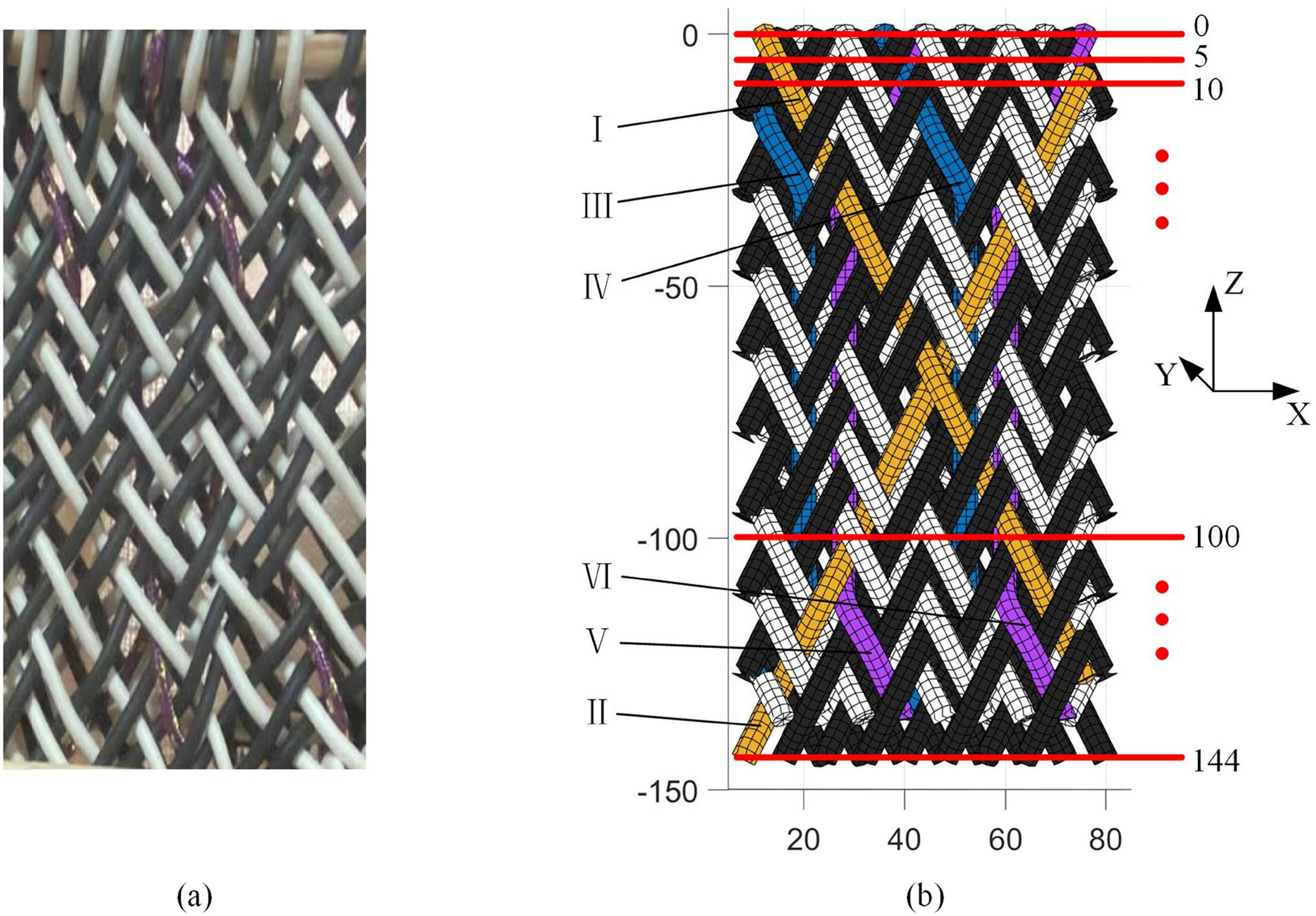
Comparison of experimental samples and numerical models of three-dimensional cross-linked braided preforms. (a) Experimental samples. (b) Preform slicing solution.
In order to verify the consistency between the experimental samples of the preform and the numerical model, the braided yarn I, II and cross-linked yarn III, IV, V, VI shown in Figure 15(b) are taken as the research objects. Divide the preform and numerical model into 30 groups of slices along the Z direction, and the X-coordinates and Y-coordinates of the cross-section centers of yarns I, II, III, IV, V, and VI in all slices are measured, as shown in Figures 16 and 17.

X-coordinates of yarn cross-section centers. (a) X-coordinates of yarn I. (b) X-coordinates of yarn II. (c) X-coordinates of yarn III. (d) X-coordinates of yarn IV. (e) X-coordinates of yarn V. (f) X-coordinates of yarn VI.

Y-coordinates of yarn cross-section centers. (a) Y-coordinates of yarn I. (b) Y-coordinates of yarn II. (c) Y-coordinates of yarn III. (d) Y-coordinates of yarn IV. (e) Y-coordinates of yarn V. (f) Y-coordinates of yarn VI.
The coefficient of determination R
2 is used as an indicator to evaluate the consistency between the experimental samples of the preform and the numerical model. Record 30 coordinates (x
1, y
1), (x
2, y
2), …, (x
30, y
30) of the measurement curve of the experimental samples and the 30 coordinates
R 2 of the X-coordinate and Y-coordinate of yarns I, II, III, IV, V, and VI are calculated according to equation (18), and the results are all greater than 0.8, which proved the high degree of agreement between the preform and the numerical model, as shown in Table 2.
R-square of the X-coordinate and Y-coordinate of yarns I, II, III, IV, V, and VI
| X-coordinate of yarn I | Y-coordinate of yarn I | X-coordinate of yarn II | Y-coordinate of yarn II | |
|---|---|---|---|---|
| R 2 | 0.944 | 0.852 | 0.976 | 0.934 |
| X -coordinate of yarn III | Y -coordinate of yarn III | X -coordinate of yarn IV | Y -coordinate of yarn IV | |
| R 2 | 0.912 | 0.906 | 0.872 | 0.928 |
| X -coordinate of yarn V | Y -coordinate of yarn V | X -coordinate of yarn VI | Y -coordinate of yarn VI | |
| R 2 | 0.891 | 0.872 | 0.836 | 0.917 |
5 Conclusion
In this article, a three-dimensional cross-linked braiding process was designed by combining the advantages of traditional rotary two-dimensional braiding and three-dimensional braiding, which can braid three-dimensional preforms with low porosity and dense surface yarns. This article described the carrier motion mechanism of three-dimensional cross-linked braiding, analyzed the carrier motion law and yarn morphology, and used numerical simulation to obtain the yarn trajectory inside the preforms initially. On this basis, it was found that the geometrical model of the preforms had problems such as high porosity and loose structure, which are quite different from the real fabric. As a result, an optimization algorithm was proposed to make the fabric compact by gathering the yarn to the center of the fabric. The numerical model with compact structure and low porosity was obtained by extracting the yarn coordinates on multiple cross-sections of the preform and substituting them into the optimization algorithm. In this article, the accuracy of the preform structure was further demonstrated by preparing a three-dimensional cross-linked preform and comparing its spatial position with the geometric model, which provides guidance for the subsequent use of the preform geometric model to predict the structural mechanical properties of fabrics in simulation and thus reduce the experimental cost.
-
Funding information: The authors disclosed receipt of the following financial support for the research, authorship, and/or publication of the article: This work was supported by the Special Fund of Scientific and Technological Achievements Transformation in Jiangsu Province (BA2018061), the Applied Research Project of Public Welfare Technology of Zhejiang (LGG20E030002), and the Scientific Research Starting Foundation of Shaoxing University (13011001002/207).
-
Conflict of interest: Authors state no conflict of interest.
References
[1] Patnaik, A., Patnaik, S. (2020). Fibres to smart textiles: Advances in manufacturing, technologies, and applications. CRC Press‒Taylor and Francis Publishing Group, Oxfordshire.10.1201/9780429446511Search in Google Scholar
[2] Sontag, T., Gries, T., Ko, F. (2015). Advances in 3D textiles. Woodhead Publishing Ltd (Cambridge).Search in Google Scholar
[3] Yordan, K. (2014). Braiding technology for textiles. Woodhead Publishing, Cambridge.Search in Google Scholar
[4] Yordan, K. (2016). Advances in braiding technology. Woodhead Publishing, Cambridge.Search in Google Scholar
[5] Midani, M., Hassanin, A., Hamouda, T., Seyam, AFM. (2023). Multiscale textile preforms and structures for natural fiber composites. Elsevier Limited, Amsterdam.Search in Google Scholar
[6] Chengjie, D., Zhuo, M., Yujing, Z., Yize, S. (2019). Modeling and analysis of the carrier arrangement in square rotary braiding. Textile Research Journal, 89, 4208–4219. 10.1177/0040517519828998.Search in Google Scholar
[7] Shao, G., Sun, Z., Chen, G., Zhou, Q., Wang, Z., Wang, B. (2021). Designing of the tracks and modeling of the Carrier Arrangement in Square Rotary Braiding Machine. Applied Sciences-Basel, 11, 7861. 10.3390/app11177861.Search in Google Scholar
[8] Glessner, P., Kyosev, Y. (2021). Carrier delay-based method for development of the tracks for the transitions between patterns on 3D braiding machines with continuous rotating horn gears. Textile Research Journal, 91, 2833–2845. 10.1177/00405175211026533.Search in Google Scholar
[9] Gu, Q., Quan, Z., Yu, J., Yan, J., Sun, B., Xu, G. (2019). Structural modeling and mechanical characterizing of three-dimensional four-step braided composites: A review. Composite Structures, 207, 119–128. 10.1016/j.compstruct.2018.09.065.Search in Google Scholar
[10] Sun, X. K., Sun, C. J. (2004). Mechanical properties of three-dimensional braided composites. Composite Structures, 65, 485–492. 10.1016/j.compstruct.2003.12.009.Search in Google Scholar
[11] Hao, W., Liu, Y., Huang, X., Liu, Y., Zhu, J. (2018). A Unit-cell model for predicting the elastic constants of 3D four directional cylindrical braided composite shafts. Applied Composite Materials, 25, 619–633. 10.1007/s10443-017-9639-z.Search in Google Scholar
[12] Bilisik, K. (2011). Three-dimensional axial braided preforms: experimental determination of effects of structure-process parameters on unit cell. Textile Research Journal, 81, 2095–2116. 10.1177/0040517511414978.Search in Google Scholar
[13] Yordan, K. (2018). Numerical Modelling of 3D Braiding Machine with Variable Paths of the Carriers. Applied Composite Materials, 25, 773–783. 10.1007/s10443-018-9714-0.Search in Google Scholar
[14] Kamble, Z., Behera, B. K. (2022). A novel geometric model of four-directional 3D braided preforms. Journal of Industrial Textiles, 51, 1701–1715. 10.1177/1528083720918856.Search in Google Scholar
[15] Zhou, Y., Li, H., Deng, Z. M. (2022) Mathematical modelling of complicated 3D woven fabrics. Journal of the Textile Institute, 113, 25–32. 10.1080/00405000.2021.1945200.Search in Google Scholar
[16] Gideon, R. K., Zhou, H., Wu, X., Sun, B., Gu, B. (2016). Finite element analysis of 3D circular braided composites tube damage based on three unit cell models under axial compression loading. International Journal of Damage Mechanics, 25, 574–607. 10.1177/1056789515605568.Search in Google Scholar
[17] Zhang, L., Hu, D., Wang, R., Zeng, Y., Cho, C. (2019). Establishing RVE model composed of dry fibers and matrix for 3D four-directional braided composites. Journal of Composite Materials, 53, 1917–1931. 10.1177/0021998318815735.Search in Google Scholar
© 2024 by the authors, published by De Gruyter
This work is licensed under the Creative Commons Attribution 4.0 International License.
Articles in the same Issue
- Characterization of viscoelastic properties of yarn materials: Dynamic mechanical analysis in the transversal direction
- Analysis of omni-channel implementations that are preferred by consumers in clothing sector
- Structural modeling and analysis of three-dimensional cross-linked braided preforms
- An experimental study of mechanical properties and comfortability of knitted imitation woven shirt fabrics
- Technology integration to promote circular economy transformation of the garment industry: a systematic literature review
- Research on T-shirt-style design based on Kansei image using back-propagation neural networks
- Research on She nationality clothing recognition based on color feature fusion with PSO-SVM
- Accuracy prediction of wearable flexible smart gloves
- Preparation and performance of stainless steel fiber/Lyocell fiber-blended weft-knitted fabric
- Development of an emotional response model for hospital gown design using structural equation modeling
- Preparation and properties of stainless steel filament/pure cotton woven fabric
- Facemask comfort enhancement with graphene oxide from recovered carbon waste tyres
- Use of enzymatic processes in the tanning of leather materials
- Optical-related properties and characterization of some textile fibers using near-infrared spectroscopy
- Network modeling of aesthetic effect for Chinese Yue Opera costume simulation images
- Predicting consumers’ garment fit satisfactions by using machine learning
- Non-destructive identification of wool and cashmere fibers based on improved LDA using NIR spectroscopy
- Study on the relationship between structure and moisturizing performance of seamless knitted fabrics of protein fibers for autumn and winter
- Antibacterial and yellowing performances of sports underwear fabric with polyamide/silver ion polyurethane filaments
- Numerical and experimental analysis of ballistic performance in hybrid soft armours composed of para-aramid triaxial and biaxial woven fabrics
- Phonetic smart clothing design based on gender awareness education for preschoolers
- Determination of anthropometric measurements and their application in the development of clothing sizing systems for women in the regions of the Republic of Croatia
- Research on optimal design of pleated cheongsam based on Kano–HOQ–Pugh model
- Numerical investigation of weaving machine heald shaft new design using composite material to improve its performance
- Corrigendum to “Use of enzymatic processes in the tanning of leather materials”
- Shaping of thermal protective properties of basalt fabric-based composites by direct surface modification using magnetron sputtering technique
- Numerical modeling of the heat flow component of the composite developed on the basis of basalt fabric
- Weft insertion guideway design based on high-temperature superconducting levitation
- Ultrasonic-assisted alkali hydrolysis of polyethylene terephthalate fabric and its effect on the microstructure and dyeing properties of fibers
- Comparative study on physical properties of bio-based PA56 fibers and wearability of their fabrics
- Investigation of the bias tape roll change time efficiency in garment factories
- Analysis of foot 3D scans of boys from Polish population
- Optimization of garment sewing operation standard minute value prediction using an IPSO-BP neural network
- Influence of repeated switching of current through contacts made of electroconductive fabrics on their resistance
- Numerical calculation of air permeability of warp-knitted jacquard spacer shoe-upper materials based on CFD
- Compact Spinning with Different Fibre Types: An Experimental Investigation on Yarn Properties in the Condensing Zone with 3D-Printed Guiding Device
- Modeling of virtual clothing and its contact with the human body
- Advances in personalized modelling and virtual display of ethnic clothing for intelligent customization
- Investigation of weave influence on flame retardancy of jute fabrics
- Balloonless spinning spindle head shape optimisation
- Research on 3D simulation design and dynamic virtual display of clothing flexible body
- Turkish textile and clothing SMEs: Importance of organizational learning, digitalization, and internationalization
- Corrigendum To: “Washing characterization of compression socks”
- Study on the promotion multiple of blood flow velocity on human epidermal microcirculation of volcanic rock polymer fiber seamless knitted fabric
- Bending properties and numerical analysis of nonorthogonal woven composites
- Bringing the queen mother of the west to life: Digital reconstruction and analysis of Taoist Celestial Beings Worshiping mural’s apparel
- Modeling process for full forming sports underwear
- Retraction of: Ionic crosslinking of cotton
- An observational study of female body shape characteristics in multiracial Malaysia
- Study on theoretical model and actual deformation of weft-knitted transfer loop based on particle constraint
- Design and 3D simulation of weft-knitted jacquard plush fabrics
- An overview of technological challenges in implementing the digital product passport in the textile and clothing industry
- Understanding and addressing the water footprint in the textile sector: A review
- Determinants of location changes in the clothing industry in Poland
- Influence of cam profile errors in a modulator on the dynamic response of the heald frame
- Quantitative analysis of wool and cashmere fiber mixtures using NIR spectroscopy
- 3D simulation of double-needle bar warp-knitted clustered pile fabrics on DFS
- Finite element analysis of heat transfer behavior in glass fiber/metal composite materials under constant heat load
- Price estimation and visual evaluation of actual white fabrics used for dress shirts and their photographic images
- Effect of gluing garment materials with adhesive inserts on their multidirectional drape and bending rigidity
- Optimization analysis of carrier-track collision in braiding process
- Numerical and experimental analysis of the ballistic performance of soft bulletproof vests for women
- The antimicrobial potential of plant-based natural dyes for textile dyeing: A systematic review using prisma
- Influence of sewing parameters on the skin–fabric friction
- Validation by experimental study the relationship between fabric tensile strength and weave structures
- Optimization of fabric’s tensile strength and bagging deformation using surface response and finite element in stenter machine
- Analysis of lean manufacturing waste in the process flow of ready-to-wear garment production in Nigeria
- An optimization study on the sol–gel process to obtain multifunctional denim fabrics
- Drape test of fully formed knitted flared skirts based on 3D-printed human body posture
- Supplier selection models using fuzzy hybrid methods in the clothing textile industry