Study on theoretical model and actual deformation of weft-knitted transfer loop based on particle constraint
-


Abstract
In order to derive the structural properties and deformation behavior of the weft-knitted transfer fabric, a multilayer spring-mass geometric circle model with weft-knitted transfer loop is provided in conjunction with the fabric samples’ image. Eight type-value points were utilized to control the transfer loop’s morphological structure. Connections between the type-value points and the particle system were established. Non-uniform rational B spline curves and texture mapping were utilized to create the three-dimensional impression of the weft-knitted transfer loop. By measuring the offset of the type-value points in conjunction, the actual deformation of the weft-knitted transfer fabric was determined. Utilizing a cylindrical envelope box for collision detection, the possible unreasonable interpenetration phenomenon in the simulation was solved, and thus a stable weft-knitted transfer loop structure was obtained. Using Microsoft Visual Studio and C#, the deformation of the weft-knitted transfer fabric was simulated, the simulated weft-knitted transfer fabric’s deformation pattern accurately depicts the fabric’s three-dimensional structure and deformation behavior while also matching the structural characteristics of the fabric sample. The findings demonstrate that the theoretical structural model of weft-knitted transfer fabric constructed can accurately represent the loop’s structure, and the actual deformation of the simulated weft-knitted transfer fabric is consistent with the deformation characteristics of the fabric sample. Weft-knitted transfer fabric’s deformation behavior may be effectively reflected by the multilayer spring-mass geometric circle model, allowing for the modeling of the fabric’s morphology and 3D structure.
1 Introduction
Weft-knitted transfer fabric is based on ribbed tissue and employs transfer technology to transfer the loops to other needles to make a fabric that is now commonly utilized in the manufacturing of shoe materials as well as some high-end T-shirts and fashion lingerie. The interruption of the longitudinal rows of the loops at the transfer point, which results in structural characteristics like dimples, holes, slanted, or twisted loops, gives the fabric its characteristic geometric modeling and deformation behavior.
To mimic the look of weft-knitted materials, numerous academics have developed a number of loop models for geometric modeling. A knitted loop in its relaxed condition was idealized and flattened in the early classic Peirce loop model [1]. As an improvement, the Leaf and Glaskin model [2] was created to represent the thickness and curvilinear shape of the loop laterally. Additionally, the Munden model [3] regarded the loop as a whole elastomer and provided an explicit mathematical link between loop length and fabric size. The fabric simulation based on the geometric model, however, lacks a strong sense of three-dimensionality and can only loosely imitate the knitted fabric’s exterior morphology.
It is necessary to create a physical model of the fabric in order to replicate the accuracy and true deformation of weft-knitted transfer fabric. There are three primary physical models that are frequently utilized to weft-knitted fabrics: the knitted loop model, the classic spring-mass model, and the traditional spring-mass model coupled with the loop model [4,5]. Meissner and Eberhardt [6] proposed the conventional spring-mass model, which determines the type-value point of the loop by computing the mass’s displacement and speed to acquire the fabric’s changing shape; however, it is challenging to replicate the local deformation of the knitted loop. The knitted coil model proposed by Kaldor et al. [7] had physical characteristics that could accurately depict the force deformation of the coil, but the computing effort was quite high and the real-time simulation software was subpar. It was possible for Yuksel et al. [8] to mesh the fabric and simulate the coil morphology of a variety of weft-knitted fabrics, but they were unable to see the three-dimensional structural characteristics of the knitted loops and the relationship between the strings of loops.
Spline curves are utilized to imitate the three-dimensional structure of weft-knitted loops in order to enhance the three-dimensional effect of loops. A true 3D simulation of weft-knitted loops, which is widely used in the simulation of weft-knitted fabric structures, can be achieved by using non-uniform rational B spline (NURBS) curves to build a 3D loop cycle cell geometry model for weft-knitted fabrics. This allows the fabric to exhibit a particular tilt phenomenon. Li et al. [9] addressed the points on the NURBS curve by back-calculating the control points to address the issue of string set continuity following curve deformation. Cong et al. [10] inserted auxiliary points into the control points, solving the problem of reverse calculation of control points. Better practical results can be obtained when the adaptable and reliable qualities of NURBS curves are combined with them, and they are frequently employed in the 3D simulation of weft-knitted materials.
To accurately represent the fabric’s deformation behavior, the spring-mass model is included to the structural simulation of weft-knit transfer fabric. The influence of the loop structure on the fabric deformation was considered, but the effect of the material on the deformation of the fabric was not considered. The density of the fabric and the type of yarn used have an impact on the weft-knitted loop form [11,12]. At this point, the following presumptions are made to simplify the modeling of loops:
a. Regardless of the hairiness on the yarn surface, the thickness of the yarn is uniform and consistent.
b. The geometric center line of the virtual yarn is supposed to pass through the loop type-value point, and it is assumed that the yarn has a circular cross-section with a radius of r.
c. The yarn is also expected to still be smooth and continuous after being deformed by force.
A three-dimensional loop theoretical model of weft-knitted transfer loops is established on the basis of an improved multi-layer spring-mass point model, which is also a physical model, connected by NURBS curves, in order to address the issue that the traditional spring-mass point model combined with the loop geometry model produces the physical deformation behavior that does not match the weft-knitted transfer fabric samples. Based on the analysis of samples of weft-knitted transfer fabric, the established model is located in a global three-dimensional coordinate system with the fabric width direction as the x-axis, the fabric height direction as the y-axis, and the fabric thickness direction as the z-axis. By constructing linear equations between particles and type-valued points and changing the common mass-spring unit from a two-dimensional model to a three-dimensional model in this particle system, the deformation behavior of the weft-knitted transfer fabric simulation may be enhanced. The weft-knitted transfer fabric’s distortion pattern and thickness may be recreated, thanks to the dimensional springs connecting each particle on the multi-layer spring-mass point model to one another. The weft-knitted transfer fabric yarn simulation is made more realistic by using NURBS and texture mapping. By measuring the offset of the loop type-value to determine the mass displacement and then simulating the deformation behavior of the weft-knitted transfer fabric, the relationship between loop deformation and particle displacement is obtained in order to address the issue of cascading after loop deformation. It is discovered that particle displacement and loop deformation are related. Based on the structural features of the weft-knit transfer fabric, a three-dimensional loop theoretical model of the fabric is developed. In addition, the samples of the fabric are knitted using 600D polyester yarn, and the models after deformation are contrasted with the samples. The weft-knitted transfer fabric produced by the simulation exhibits realistic deformation behavior, according to experiments, demonstrating how the technology increases simulation efficiency. The approach and framework described in this study offer a quick process for visualizing the 3D structure and deformation pattern of weft-knitted transfer textiles, and they can assist designers in producing intricate weft-knitted transfer fabric designs.
2 Geometric model
The deformation behavior of weft-knit transfer textiles cannot be accurately simulated by many of the present modeling techniques for weft-knitted fabrics, despite the fact that they may often provide comparatively decent simulations [13,14,15]. This is due to the fact that the shape of the transfer loop and the surrounding loop affect the variance in the structure of weft-knitted transfer loop textiles. The spring-mass model is a physical model that can be more practical and efficient in analyzing the force deformation of fabrics. The spring-mass model is also frequently used in woven garment simulation because it is straightforward to use and makes it easy to get the desired effect. With the exception of thickness, the deformation behavior of weft-knitted transfer textiles is comparable to that of woven fabrics in terms of stretching and bending. Additionally, modeling is made simpler by representing the weft-knitted transfer loop structure as a mesh, and this is why an enhanced multilayer spring-mass point model based on it is suggested in this article.
2.1 Improved particle system
On a unique double-sided transfer circular knitting machine with a loop-forming system and a transfer system on both the needle and cylinder triangle, weft-knitted transfer fabric is knit. The transfer loops are positioned between the front and back loops on the needle that is receiving the loops as it moves through the loop spreader, picks them up from the transfer needle, and continues knitting. The weft-knitted transfer fabric’s front and back loops are situated in parallel and independent cube areas, and when the thickness of the individual loops is taken into consideration, the loops are viewed as forming a cube.
An improved model of the particle system of weft-knitted transfer fabric is described, taking into consideration the interaction between neighboring loops and the deformation behavior of the transfer loops. Without abandoning the mass-spring method’s stability and simplicity, the structural depiction of weft-knitted transfer textiles is achieved. Several layers of spring-mass systems are connected by structural springs in order to characterize the complicated transfer loop organization and its structural features. Due to their extremely tiny coefficients, bending springs are not taken into consideration in this study. Instead, extension and shear springs are utilized to represent multi-layer spring masses instead. Calculating the particle velocity along with the coordinates of the spots allows one to predict how the weft-knitted transfer fabric would deform.
Particles are evenly dispersed across a grid layer made of i × j × z, as shown in Figure 1. The evenly dispersed particles in the model are referred to as p i,j,z , and there are i × j × z (z = 4) masses in it, where i is the index of the number of columns in which the particles are distributed, j is the index of the number of rows in which the particles are distributed, and z is the index of the number of layers in which the particles are distributed. The spring connecting the two particles is known as an extension spring when just one of the two particle index numbers is different and this difference index number differs by a value of 1. The spring connecting the two masses is known as a shear spring when two of the mass index numbers differ and the difference between the two index values is 1 [16,17].
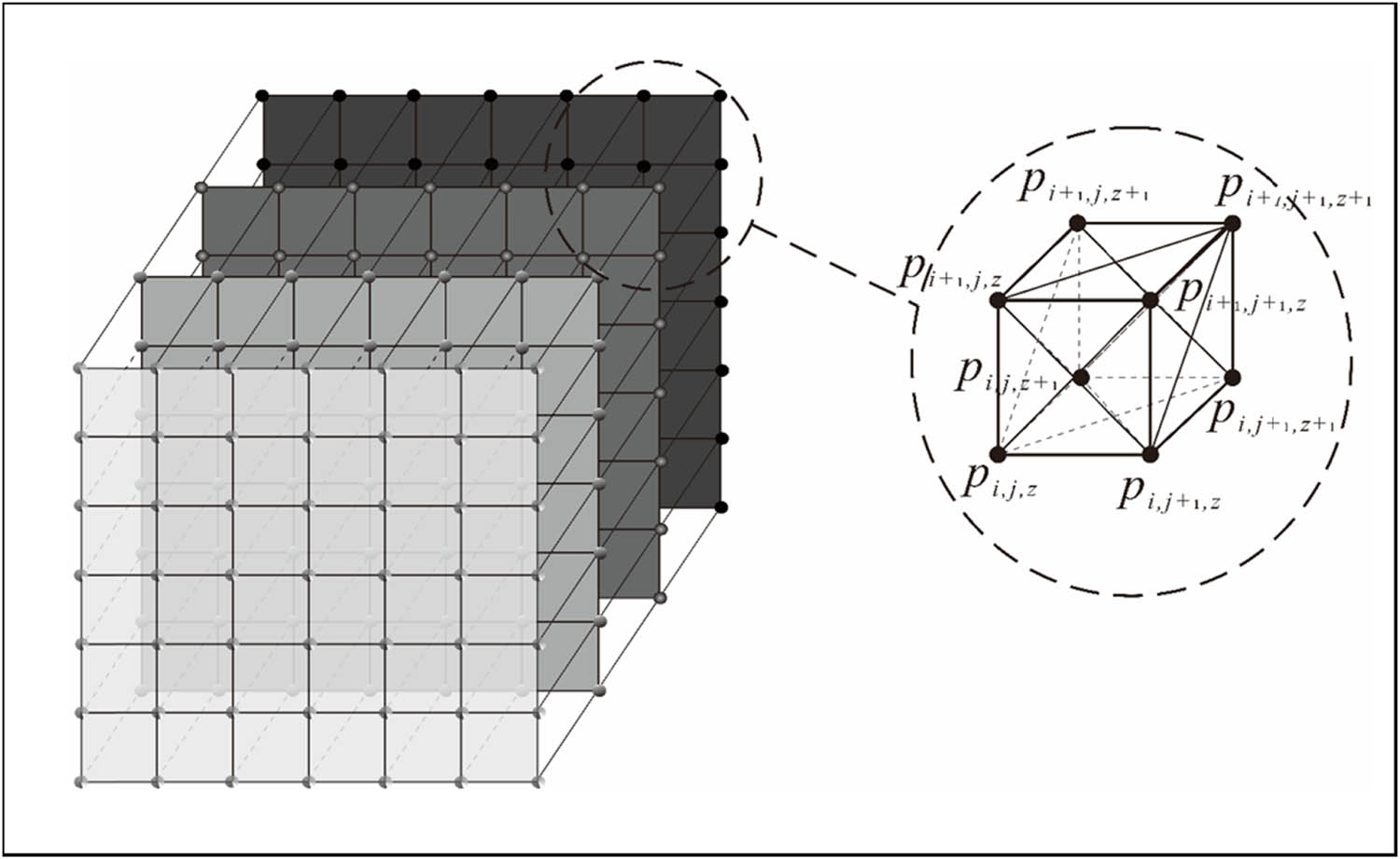
Multi-layer spring-mass model for weft-knitted transfer fabric.
2.2 Geometrical model
The smallest component of a weft-knit fabric is the loop [18]. When modeling the composition of a weft-knitted transfer fabric, the loop spring-mass geometry model of the ribbed tissue should be deformed to create a multi-layer transfer loop model. The loop transfer organization, as depicted in Figure 2, includes the loops of the present knitting row as well as the suspended arc of the loop being transferred, in addition to the weft-knitted transfer fabric.
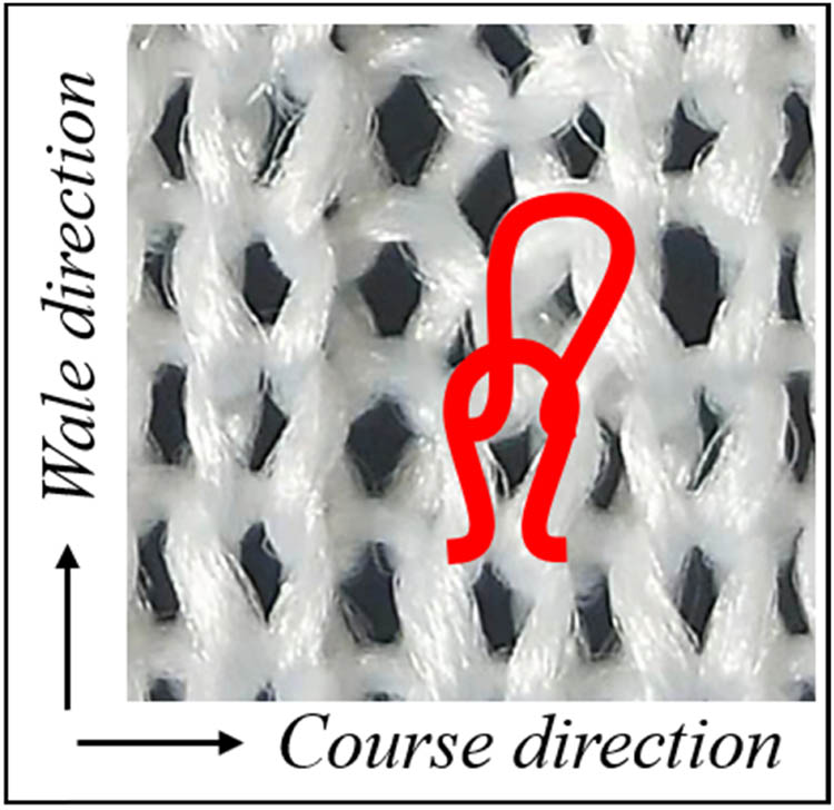
Weft-knitted transfer fabric illustration.
When applied to a weft-knitted transfer fabric, a geometric loop model is developed by treating each stitch as if it were a separate unit in order to accurately depict the genuine deformation behavior of a loop. It is frequently simpler to combine similar models to make complicated loop structures since the two rows of this particular model form a complete loop with single points connecting the unit loops and the loops deforming as the masses are displaced. It is possible to represent the weft-knitted transfer loop as a multi-layer spring-mass geometric loop using a structural analysis of the weft-knitted transfer fabric tissue, as shown in Figure 3. This is true regardless of how the transfer loop affects the shapes of the surrounding loops.
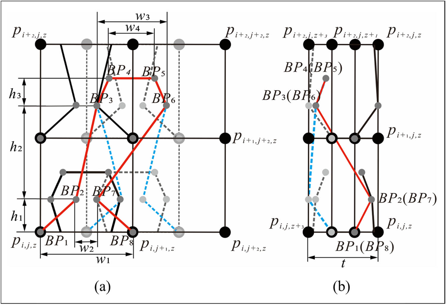
Multilayer spring-mass geometric circle model with weft-knitted transfer loop. (a) Main view and (b) side view.
In Figure 3, h = h 1 + h 2, w 1 is the loop distance, and t is the thickness. The black dots p i,j,z represent the model’s particles, while the grey dot BPs represent the type-value points on the transfer loop’s center line. The spring-mass model is connected to the type-value points of the loop and the particles are given physical attributes, causing the loop’s form to change when the mass is strained. This results in a more physically accurate influence on the force acting on the loop. Weft-knitted transfer fabric’s loop structure was precisely simulated by measuring and analyzing the loop’s structural properties using an ultra-deep field microscope (VHW-600), as indicated in Table 1.
Sizes for weft-knitted transfer fabric (unit: mm)
| h1 | h2 | h3 | w1 | w2 | w3 | w4 | |
|---|---|---|---|---|---|---|---|
| 1# | 0.46 | 1.23 | 0.77 | 1.62 | 0.53 | 1.26 | 0.73 |
| 2# | 0.51 | 1.17 | 0.82 | 1.54 | 0.62 | 1.38 | 0.82 |
| 3# | 0.48 | 0.92 | 0.64 | 1.49 | 0.51 | 1.27 | 0.75 |
| 4# | 0.50 | 1.25 | 0.72 | 1.61 | 0.54 | 1.36 | 0.82 |
| 5# | 0.42 | 0.96 | 0.74 | 1.52 | 0.64 | 1.25 | 0.83 |
| 6# | 0.43 | 1.11 | 0.78 | 1.48 | 0.52 | 1.21 | 0.86 |
| Average | 0.47 | 1.11 | 0.75 | 1.54 | 0.56 | 1.29 | 0.80 |
The coordinates of each type-value point in the transfer loop structure are shown in Table 2 in accordance with the measurement results of the weft-knitted transfer loop, which establish a linear relationship between the type-value points of the weft-knitted transfer fabric and the particles in the multilayer spring-mass system. p i,j,z is used as the loop coordinates’ points of reference. When n = 0, it refers to the coordinates of the type-value point on the X-axis. In the XOY plane, BP1 and BP8, BP2 and BP7, BP3 and BP6, BP4 and BP5, all have identical y-coordinates. In the YOZ plane, their z-coordinates are equal.
Coordinates for each type-value point in the multilayer spring-mass geometric weft-knitted transfer loop model
| Data point | Coordinates |
|---|---|
| BP1 |
|
| BP2 |
|
| BP3 |
|
| BP4 |
|
| BP5 |
|
| BP6 |
|
| BP7 |
|
| BP8 |
|
3 3D surface of yarn based on NURBS
Weft-knitted transfer loops are modelled using a loop model based on NURBS curves, which also gives the yarn a textured quality, to improve its three-dimensional look. The control points that have been provided plus a few coil parameter values decide the NURBS curve’s form [19]. In order to replicate weft-knitted transfer loops, a NURBS-like curve is employed, which is an excellent depiction of the interlocking connection between the loops. The loop’s type-value points of are used as the control points of the NURBS curve. As a result, the loop deformation will be more realistic and flexible.
3.1 NURBS curve description
The mathematical formulas used in NURBS enable the creation of realistic, smooth contours and appearances by using curves and surfaces as weighting factors and denominators [20]:
where P i (i = 0, 1, 2… n) is the position vector of the feature polygon’s control vertices and ω i is the weight factor that corresponds to P i and is derived from the node vector U = [u 0, u 1, …, u i+k+1]. In this study, we limit the first and last weight factors to ω 0 and ω i > 0, ω 1, …, ω i–1 ≥ 0, and make sure that the next k consecutive weight factors are not both 0 at the same time. The kth B-sample basis function is called N i,k (u). Combining the de Boor-Cox recursive formula will get the value of ω i :
The two end nodes with repetition k + 1 in the weft-knitted transfer loop model are frequently taken as u 0 = u 1 = u k , u n = u n+1 = … = u n+k+1 in order to avoid making the denominator 0 and to maintain the NURBS curve features. The defining domain of the curve may be calculated as u[u k, u n+1] = [0,1] by choosing 0 and 1 as the values of the two end nodes.
Using the equation for the surface, a NURBS surface transfers an area in two dimensions to a surface in three dimensions:
where ω i,j are the weight factors connected to the control vertices P i,j (i = 0, 1, …, m; j = 0, 1, …, n) in a topological matrix array. The weight factors at the four corner vertices are configured to be positive, ω 0,0, ω m,0, ω 0,n , ω m,n > 0; the remaining weight factors ω i,j ≥ 0, and k × 1 weight factors cannot be equal to 0 at the same time. The canonical B-sample basis for k times in the u-direction is N i,k (u)(i = 0, 1, …, m), the canonical B-sample basis for l times in the v-direction is N i,l (u) (i = 0, 1, …, n). The nodal vectors U = [u 0, u 1, …, u m+k+1] and V = [u 0, u 1, …, u i+k+1] in the u-direction and v-direction, as well as the de Boor-Cox recurrence, define N i,k (u) and N i,l (u), the formula is established.
3.2 Simulation of yarn strands
A specific length, twist, and three-dimensional effect when bent in a loop are characteristics of the three-dimensional solid yarns utilized to create weft-knitted transfer fabrics. This study simulates the twist effect of the strands based on the yarn texture in order to improve the three-dimensional simulation of weft-knitted transfer fabric. To realize the simulation of the yarn surface texture, a texture mapping approach is used.
Make sure the points on the surface of the weft-knitted transfer fabric correspond to the points in the texture pattern, which means map the points on the two-dimensional coordinate system to the global three-dimensional coordinate system. To cover the surface of the weft-knitted transfer fabric [21], repeat the texture mapping along a specific direction on a plane made up of a series of polygons. According to Figure 4, the texture pattern is situated in two dimensions, with the texture coordinates being each vertex coordinate T(s, t), while the image of the weft-knitted transfer fabric is situated in three dimensions with the coordinates of its upper vertices as (x, y, z). Only when the weft-knitted transfer fabric’s spatial coordinates (x, y, z) have been determined with respect to (s, t), the two-dimensional texture pattern can be mapped onto the fabric’s surface. The weft-knitted transfer fabric has spots on its surface whose function is P(u,v), and whose coordinates are
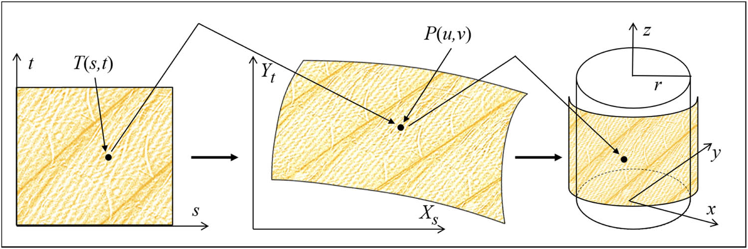
Process of transferring 2D textures to 3D.
4 Deformation simulation
A weft-knitted transfer fabric’s actual deformation pattern relies on how the transfer loops are connected to the loops next to them, and because of the structure of the transfer loops, the shape of these loops does not perfectly match the geometric model in the ideal state. Weft-knitted transfer fabric’s deformation behavior is simulated by analyzing the deformation mechanism of the distorted loops and measuring the deflection of the deformed loops.
4.1 Deformation principle of loop
The loop of a weft-knitted transfer fabric is made up of type-valued points with determined coordinates from nearby mass points. On the basis of the multilayer spring-mass point model previously created, the linear relationship between type-value points and mass points is constructed. On weft-knitted transfer fabrics, the force balance of the internal fabric structure is disturbed when several loop types, such as loop forming, loop tucking, and loop transferring, are present.
The length of the extension and shear springs that link these particles together is based on where the mass point is located. The type-valued points move together with the mass points as a result of the forces and displacements acting on the mass points, which results in deformation. The deformation principle of a weft-knitted transfer fabric based on mass constraint is depicted in Figure 5, with the transfer stretched loop serving as the central loop and the red arrow indicating the direction of force on the transfer loop. As a result of the force’s displacement of the surrounding masses and the disruption of the balance of forces between the loops, a deformation force is produced [22,23].
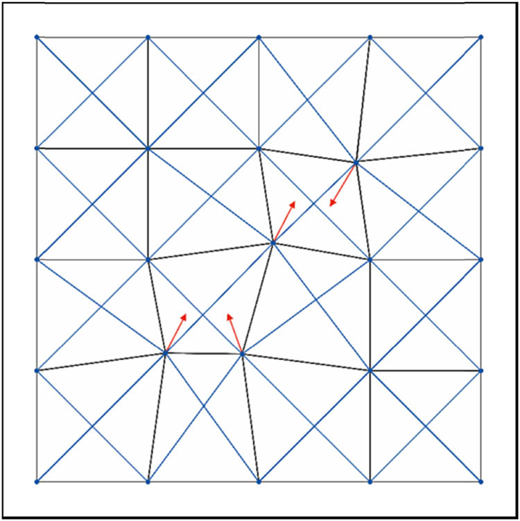
Deformation principle for weft-knitted transfer fabric.
4.2 Calculating the offset of the deformed loop
The offset of each type-value point of the weft-knitted transfer loop in the x, y, and z directions was measured in conjunction with the sample of weft-knitted transfer fabric after the deformation principle of the theoretical model of the loop was examined using particle constraints. With positive movement of the type-value points along the X, Y, and Z axes being positive and negative movement along the X, Y, and Z axes being negative, Table 3 displays the average offset of each type-value point of the loop, taken from a sample of the weft-knitted transfer fabric, in mm. The offset of the particle may be determined from the linear equation of the particle and the type-value point by entering the observed values in Table 2.
Average offset of each type-value point of loops in weft-knitted transfer fabric
| Data point | Δdx | Δdy | Δdz |
|---|---|---|---|
| BP1 | 0.094 | 0.072 | −0.034 |
| BP2 | 0.117 | 0.135 | −0.062 |
| BP3 | −0.142 | −0.164 | 0.093 |
| BP4 | −0.156 | −0.144 | 0.084 |
| BP5 | −0.158 | −0.146 | 0.082 |
| BP6 | −0.165 | −0.172 | 0.106 |
| BP7 | −0.192 | 0.128 | −0.068 |
| BP8 | −0.122 | 0.065 | −0.036 |
The location of the particle changes and the spring’s length varies, resulting in a force, which is added to the multilayer spring-mass geometry loop model. The mass point is displaced as a result of the force acting on it, which is solved numerically using the Velocity-Verlet technique [24]. A loop deformation, or efficient and stable dynamic change in the coordinates of the type-valued points connected to the mass point, is the end consequence of the force’s displacement of the particles surrounding it.
4.3 Yarn continuity
Due to the absence of limitations between moving particles during simulation, crosstalk, or interpenetration of coils caused by particle displacement may be excessive. Collision detection and response in computer graphics can make sure that there is no significant object penetration. The central axis of the cylindrical envelope is formed by a set of neighboring type-valued points, and a number of points are evenly distributed among them using the cylindrical envelope collision detection method [25]. A collision problem can be detected by determining whether two columns intersect, and when it is, the yarns are moved to the position of the mass point at the previous instant for the yarns that have collided, adjusting the yarn positions to be reasonable and not mutually exclusive. The yarns will be positioned to avoid tangling with one another. In order to prevent excessive stringing of the loops, it is also possible to raise the spring stiffness factor and adjust the plenum’s displacement range.
5 Results and discussion
Results from simulations and samples are compared. The simulations were carried out on a computer equipped with an AMD Ryzen 7 5800U central processing unit (specifications: 3.20 GHz and 16 GB RAM), and the theoretical structural models and actual deformation simulations of weft-knitted transfer fabrics were based on the Microsoft Visual Studio 2017 IDE programming development platform and OpenGL 3D graphics library. This allowed for realistic structural simulations of weft-knitted transfer fabrics with a reduced computer configuration.
5.1 Implementation
The procedure of the weft-knitted transfer fabric simulation is depicted in Figure 6 in order to provide a realistic simulation.
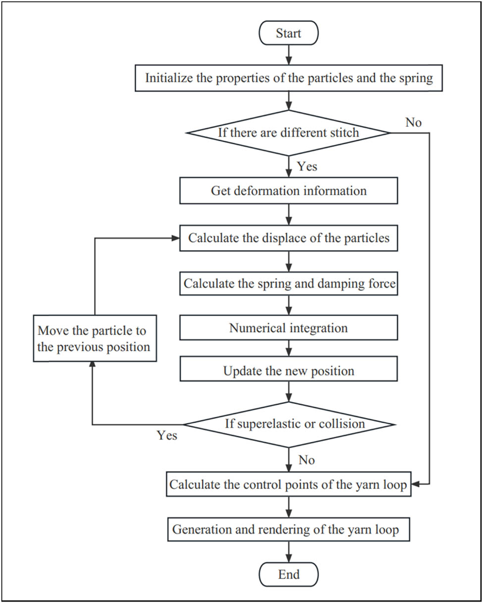
Process of transferring 2D textures to 3D.
The physical characteristics of the particles are defined, the forces acting on the particles are updated, the particles’ velocity and displacement are calculated, the particles’ updated position is obtained, and the yarn’s hyperelasticity and collisions are taken into account in order to simulate the deformation dynamics of the particles [26]. These techniques allow for the structural simulation of the deformation behavior of weft-knitted transfer textiles. Using the integrated programming tool Microsoft Visual Studio 2017, it is possible to visualize the 3D morphological properties of the weft-knitted transfer loop structure on a computer screen.
5.2 Initializing configuration
Despite the complicated construction of weft-knitted transfer fabrics, a consistent pattern is usually present. Every three ways on a double-sided transfer circle machine, a transfer loop system is present. Typically, this system consists of a positive transfer loop and a negative transfer loop with a needle cylinder and needle plate. The geometry of the transfer loops varies depending on where they are placed in relation to the loop-shifting system and the loop-forming system, and the loops across the line are distorted by pushing and squeezing [27]. In addition, the deformation of the transfer loop is also closely related to the surrounding loops; if all the loops around the transfer loop are present, the loop at the transfer loop is disconnected longitudinally, and the loop above the transfer loop is deformed into a set loop; if there are no loops below the transfer loop, the transfer loop sinks arc without a series of sets, and becomes a set loop; and if there are no loops above the transfer loop, the fabric at the transfer loop naturally converts from double sided to single sided. When all the loops around the transfer loop are not present, the transfer loop has an effect on the deformation of the loop on the other side in addition to the characteristics described above.
According to the technique outlined in this research, the weft-knitted transfer fabrics were categorized and discussed, and each theoretical structural model was created to mimic their deformation behavior. Before the simulation begins, the fabric’s theoretical structural model is set as the initial state of the deformation simulation, and the initial state of the undeformed model is set as uniform but unstable, with the same loop lengths for the various structures. The theoretical structural model of the weft-knitted transfer fabric is shown in Figure 7. Depending on which direction the loop transfer is occurring, the loop transferring structure may be classified as either forward (a)–(f) or backward (h)–(m). For example, single-row transfer loops (a)–(d) and cross-row transfer loops (e) and (f) may be distinguished between forward shifting coils and can be categorized as single-row transfer loops. When simulating single row transfer deformation, the morphology of the loops surrounding and centered on the loop – with all loops present in case of (a), all loops absent in case of (b), all loops absent in case of (c), and none present in case of (d) – is the key factor determining loop deformation.
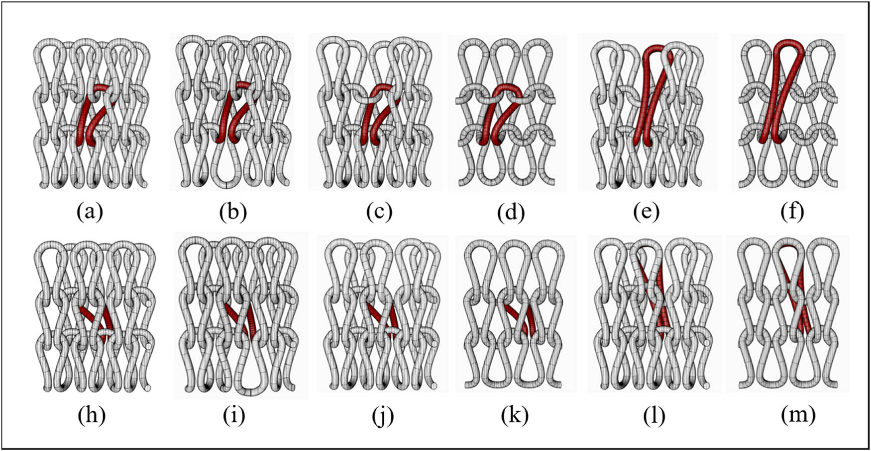
Theoretical structural model of weft-knitted transfer fabrics. (a) Front side of single row of transfers and surrounded by loops, (b) Front side of single row of transfers and below no loops, (c) Front side of single row of transfers and above no loops, (d) Front side of single row of transfers and surrounded by no loops, (e) Front side of cross rows of transfers and surrounded by loops, (f) Front side of cross rows of transfers and surrounded by no loops, (h) Reverse side of single row of transfers and surrounded by loops, (i) Reverse side of single row of transfers and below no loops, (j) Reverse side of single row of transfers and above no loops, (k) Reverse side of single row of transfers and Surrounded by no loops, (l) Reverse side of cross rows of transfers and surrounded by loops and (m) Reverse side of cross rows of transfers and surrounded by no loops.
5.3 Fabric sample
At the start of the simulation, the tugging of the transfer loops generates a driving force that deforms the surrounding loops. The distortion of the weft-knitted transfer fabric structures varies because the forces between the various structures are out of balance. A physical image of the various types of weft-knitted transfer fabric structures is taken in Figure 8 in order to confirm the similarity between the simulated effects of the multi-layer spring-mass geometric loop model of weft-knitted transfer fabric and the fabric samples. In the weft-knitted transfer fabric structure, it can be seen from the diagram that loops with a fixed loop pattern produce a hole effect. The single- and double-sided transformation of the loop transfer fabric also produces a bump effect, and the loop-forming loops on the opposite side are impacted by the loop transfer, resulting in a left-right skew.
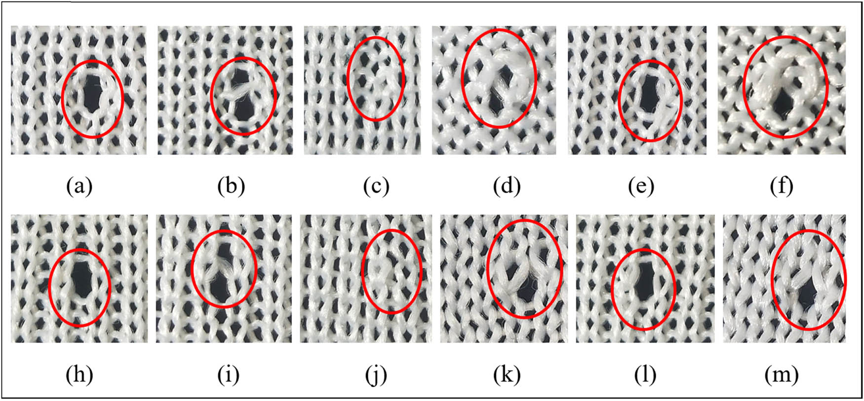
Physical image of the weft-knitted transfer fabric samples. (a) Front side of single row of transfers and surrounded by loops, (b) Front side of single row of transfers and below no loops, (c) Front side of single row of transfers and above no loops, (d) Front side of single row of transfers and Surrounded by no loops, (e) Front side of cross rows of transfers and surrounded by loops, (f) Front side of cross rows of transfers and surrounded by no loops, (h) Reverse side of single row of transfers and surrounded by loops, (i) Reverse side of single row of transfers and below no loops, (j) Reverse side of single row of transfers and above no loops, (k) Reverse side of single row of transfers and Surrounded by no loops, (l) Reverse side of cross rows of transfers and surrounded by loops and (m) Reverse side of cross rows of transfers and surrounded by no loops.
5.4 Simulation results
The approach suggested in this research has been utilized to simulate and produce images of the deformation pattern of weft-knitted transfer fabrics, as shown in Figure 9. Stringing and stretching are the causes of the structural deformation of weft-knitted transfer fabrics, and the method has been utilized to simulate and generate photos of this deformation pattern. Images (a) and (h) have all the loops around the transfer loops present, the loops are broken longitudinally at the transfer loops, and the upper loops are deformed into set loops; images (b) and (i) do not have the lower loops around the transfer loops, and in addition to the deformation characteristics in images (a) and (h), the absence of a string sleeve below the transfer loops turns the loop into a transfer loop, while in the other side, images (c) and (j) lack the loops around the transfer loops, causing the fabric to naturally change from being double-sided to single-sided; images (d) and (k) lack all of the loops around the transfer loops, causing the loops on the opposite side of the loop to deform due to the pulling influence; and images (e), (l), (f) and (m) base their interpretation of the previous images on the loops on the opposite side of the transfer loop. A left-right skew is created by compressing the center loops.
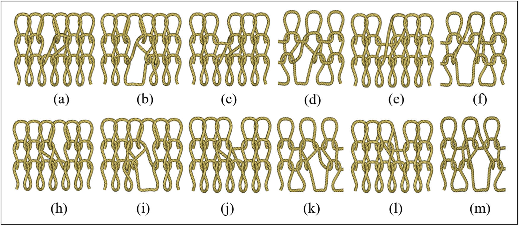
The actual deformation of weft-knitted transfer fabrics. (a) Front side of single row of transfers and surrounded by loops, (b) Front side of single row of transfers and below no loops, (c) Front side of single row of transfers and above no loops, (d) Front side of single row of transfers and Surrounded by no loops, (e) Front side of cross rows of transfers and surrounded by loops, (f) Front side of cross rows of transfers and surrounded by no loops, (h) Reverse side of single row of transfers and surrounded by loops, (i) Reverse side of single row of transfers and below no loops, (j) Reverse side of single row of transfers and above no loops, (k) Reverse side of single row of transfers and Surrounded by no loops, (l) Reverse side of cross rows of transfers and surrounded by loops and (m) Reverse side of cross rows of transfers and surrounded by no loops.
5.5 Simulation effects verification
Figures 7–9 show the validation of the simulation results, and it is clear that the simulated weft-knitted transfer fabric’s deformation pattern accurately depicts the fabric’s three-dimensional structure and deformation behavior while also matching the structural characteristics of the fabric sample. This shows how the theoretical model of the weft-knitted transfer loop based on mass constraint can accurately simulate the force deformation impact of the loop and realize the structural simulation and 3D simulation of the weft-knitted transfer fabric.
In this study, weft-knitted transfer fabric is structurally deformed and simulated in three dimensions while also investigating the theoretical model and deformation of the fabric in three dimensions based on mass constraint. The drawing performance is virtually real-time since the process is so straightforward. It is shown that the multilayer spring-mass point geometric loop model is capable of correctly simulating the deformation behavior of transfer fabric made of weft knitting.
6 Conclusion
This article proposes a theoretical model of a three-dimensional weft-knitted transfer loop developed based on particle constraints. First, considering the interaction force between adjacent coils of weft-knitted transfer fabric and the deformation behavior of the transfer loop, this study proposes a multi-layer spring-mass model for weft-knitted transfer fabric. Second, by analyzing the structure of the weft-knitted transfer loop organization, a multilayer spring-mass geometric circle model with weft-knitted transfer loop was established without considering the influence of the transfer loop on the surrounding coil shape. Finally, based on the measurement results of the weft-knitted transfer fabric’s loops, a linear relationship between the type-value points of the weft-knitted transfer fabric and the particles in the multilayer spring-mass system was established.
This article takes the type-value points obtained from the established geometric model as the control points of the NURBS curve, and introduces the NURBS curve into the geometric modeling of weft-knitted transfer fabric, which well reflects the mutual string and sleeve relationship between the coils and improves the flexibility and realism of coil deformation. Using texture mapping to transfer 2D textures to 3D enhances the three-dimensional effect of weft-knitted transfer fabric.
In order to simulate the deformation behavior of weft-knitted transfer fabric, this article analyzes the deformation principle for weft-knitted transfer fabric based on particle constraints. Based on the weft-knitted transfer fabric samples, the displacement of each type-value point of the deformation loop in different directions was measured, and the displacement of the particle was calculated by substituting the linear equation of the particle and type-value point. The use of cylindrical bounding box for collision detection has achieved vivid and practical real-time structural simulation.
This article simulates the theoretical structural model and actual deformation of weft-knitted transfer fabric, achieving structural simulation of the deformation behavior of weft-knitted transfer fabric. It is verified that the deformation of weft-knitted transfer fabrics simulated using the model proposed in this work yields a structure that matches the structural characteristics of the fabric samples. It proves that the multilayer spring-mass geometric circle model can accurately reflect the deformation behavior of weft-knitted transfer fabric. Due to the simplicity of this method, its rendering performance is almost real-time. Using Microsoft Visual Studio 2017 integrated development tools, the structural simulation and 3D simulation of weft-knitted transfer fabric were visualized on a computer screen.
Acknowledgements
The authors acknowledge the financial support from National Science Foundation of China (Grant Number 61902150).
-
Funding information: The research was financially supported by National Science Foundation of China (Grant Number 61902150).
-
Author contributions: All authors contributed to this study. Zhangjing conceived and designed the experiments, analyzed and interpreted the data, and contributed to writing the manuscript. Cong Honglian contributed to data acquisition and analysis, reviewed literature, provided intellectual input, and approved the final version of the manuscript.
-
Conflict of interest: Authors state no conflict of interest.
References
[1] Peirce, F. T. (1947). Geometrical principles applicable to the design of functional fabrics. Textile Research Journal, 17, 123–147.10.1177/004051754701700301Search in Google Scholar
[2] Leaf, G. V. (1960). Models of plain knitted loop. Journal of the Textile Institute, 51, 49–58.10.1080/19447026008662670Search in Google Scholar
[3] Munden, D. L. (1959). Geometry and dimensional properties of plain-knit fabrics. Journal of the Textile Institute, 50, 448–471.10.1080/19447025908659923Search in Google Scholar
[4] Kurbak, A., Kayacan, O. (2008). Basic studies for modeling complex weft knitted fabric structures. Part V: geometrical modeling of tuck stitches. Textile Research Journal, 78, 577–582.10.1177/0040517507087672Search in Google Scholar
[5] Kurbak, A., Alpyildiz, T. (2008). A geometrical model for the double Lacoste knits. Textile Research Journal, 78, 232–247.10.1177/0040517507081306Search in Google Scholar
[6] Meissner, M., Eberhardt, B. (1998). The art of knitted fabrics, realistic & physically based modelling of knitted patterns. Computer Graphics Forum, 17(3), C355–C362.10.1111/1467-8659.00282Search in Google Scholar
[7] Kaldor, J., James, D., Marschner, S. (2008). Simulating knitted cloth at the yarn level. In: Proceedings of SIGGRAPH 2008, Los Angeles, California, pp. 1–9.10.1145/1399504.1360664Search in Google Scholar
[8] Yuksel, C., Kaldor, J. M., James, D. L, Marschner, S. (2012). Stitch meshes for modeling knitted clothing with yarn-level detail. ACM Transactions on Graphics, 31(4), 1–2.Search in Google Scholar
[9] Li, Y., Yang, L., Chen, S., Xu, L. (2014). Three dimensional simulation of weft knitted fabric based on surface model. Computer Modelling & New Technologies, 18(3), 57.Search in Google Scholar
[10] Cong, H., Ge, M., Jiang, G. (2009). Three-dimensional simulation of warp-knitted fabric. Fibres & Textiles in Eastern Europe, 17(3), 66–69.Search in Google Scholar
[11] Balea, L., Dusserre, G., Bernhart, G. (2014). Mechanical behaviour of plain-knit reinforced injected composites: Effect of inlay yarns and fibre type. Composites Part B: Engineering, 56, 20–29.10.1016/j.compositesb.2013.07.028Search in Google Scholar
[12] Araújo, M., Fangueiro, R., Hong, H. (2003). Modelling and simulation of the mechanical behaviour of weft-knitted fabrics for technical applications: Part II: 3D model based on the elastica theory. Autex Research Journal, 12(3–4), 166–172.10.1515/aut-2003-030403Search in Google Scholar
[13] Sha, S., Jiang, G., Ma, P, Li X. (2015). 3-D dynamic behaviors simulation of weft knitted fabric based on particle system. Fibers and Polymers, 16(8), 1812–1817.10.1007/s12221-015-5254-5Search in Google Scholar
[14] Kurbak, A., Kayacan, O. (2008). Basic studies for modeling complex weft knitted fabric structures. Part II: A geometrical model for plain knitted fabric spirality. Textile Research Journal, 78, 279–288.10.1177/0040517507082351Search in Google Scholar
[15] Kyosev, Y., Angelova, Y., Kovar, R. (2005). 3D modeling of plain weft knitted structures of compressible yarn. Research Journal of Textile and Apparel, 9, 88–97.10.1108/RJTA-09-01-2005-B009Search in Google Scholar
[16] Güdükbay, U., Bayraktar, S., Koca, Ç, Özgüç, B. (2014). Particle-based simulation of the interaction between fluid and knitwear. Signal Image and Video Processing, 8(3), 415–422.10.1007/s11760-012-0308-2Search in Google Scholar
[17] Zhang, J., Baciu, G., Cameron, J, Hu, J. (2012). Particle pair system: An interlaced mass-spring system for real-time woven fabric simulation. Textile Research Journal, 82(7), 655–666.10.1177/0040517511435006Search in Google Scholar
[18] Hagège, B., Boisse, P., Billoët, J. L. (2005). Finite element analyses of knitted composite reinforcement at large strain. Revue Européenne des Eléments, 14(6–7), 767–776.10.3166/reef.14.767-776Search in Google Scholar
[19] Sha, S., Ma, P., Chapman, L. P., Jiang G., Zhang A.. (2017). Three-dimensional modeling and simulation of deformation behavior of fancy weft knitted stitch fabric. Textile Research Journal, 87(14), 1742–1751.10.1177/0040517516658518Search in Google Scholar
[20] Rajab, K., Piegl, L. A., Smarodzinava, V. (2013). CAD model repair using knowledge-guided NURBS. Engineering with Computers, 29(4), 477–486.10.1007/s00366-012-0264-zSearch in Google Scholar
[21] Peng, J., Jiang, G., Xia, F., Cong, H., Dong, Z. (2020). Deformation and geometric modeling in three-dimensional simulation of fancy weft-knitted fabric. Textile Research Journal, 90(13–14), 1527–1536.10.1177/0040517519894749Search in Google Scholar
[22] Yuksel, C., Kaldor, J. M., James, D. L, Marschner S. (2012). Stitch meshes for modeling knitted clothing with yarn-level detail. ACM Transactions on Graphics, 31, 1–12.10.1145/2185520.2335388Search in Google Scholar
[23] Alpyildiz, T., Icten, B. M., Karakuzu, R, Kurbak A. (2009). The effect of tuck stitches on the mechanical performance of knitted fabric reinforced composites. Composite Structures, 89, 391–398.10.1016/j.compstruct.2008.09.004Search in Google Scholar
[24] Huang, Q., Yang, X., Zheng, D, Zhou Q., Li H., Peng L., et al. (2022). Structural modeling and simulation of industrial flat and cylindrical axial weft-knitted fabrics. Textile Research Journal, 92(11–12), 2031–2045.10.1177/00405175211067282Search in Google Scholar
[25] Sha, S., Jiang, G., Chapman, L. P., Ma, P., Zhang, A., Cong, H., et al. (2017). Fast penetration resolving for weft knitted fabric based on collision detection. Journal of Engineered Fibers and Fabrics, 12(1), 50–58.10.1177/155892501701200106Search in Google Scholar
[26] Ru, X., Wang, J. C., Peng, L., Shi, W., Hu, X. (2022). Modeling and deformation simulation of weft knitted fabric at yarn level. Textile Research Journal, 93(11–12), 2437–2448.10.1177/00405175221134934Search in Google Scholar
[27] Zheng, P., Jiang, G. (2021). Modeling and realization for visual simulation of circular knitting transfer-jacquard fabric. Textile Research Journal, 91(19–20), 2225–2239.10.1177/0040517521994497Search in Google Scholar
© 2024 by the authors, published by De Gruyter
This work is licensed under the Creative Commons Attribution 4.0 International License.
Articles in the same Issue
- Characterization of viscoelastic properties of yarn materials: Dynamic mechanical analysis in the transversal direction
- Analysis of omni-channel implementations that are preferred by consumers in clothing sector
- Structural modeling and analysis of three-dimensional cross-linked braided preforms
- An experimental study of mechanical properties and comfortability of knitted imitation woven shirt fabrics
- Technology integration to promote circular economy transformation of the garment industry: a systematic literature review
- Research on T-shirt-style design based on Kansei image using back-propagation neural networks
- Research on She nationality clothing recognition based on color feature fusion with PSO-SVM
- Accuracy prediction of wearable flexible smart gloves
- Preparation and performance of stainless steel fiber/Lyocell fiber-blended weft-knitted fabric
- Development of an emotional response model for hospital gown design using structural equation modeling
- Preparation and properties of stainless steel filament/pure cotton woven fabric
- Facemask comfort enhancement with graphene oxide from recovered carbon waste tyres
- Use of enzymatic processes in the tanning of leather materials
- Optical-related properties and characterization of some textile fibers using near-infrared spectroscopy
- Network modeling of aesthetic effect for Chinese Yue Opera costume simulation images
- Predicting consumers’ garment fit satisfactions by using machine learning
- Non-destructive identification of wool and cashmere fibers based on improved LDA using NIR spectroscopy
- Study on the relationship between structure and moisturizing performance of seamless knitted fabrics of protein fibers for autumn and winter
- Antibacterial and yellowing performances of sports underwear fabric with polyamide/silver ion polyurethane filaments
- Numerical and experimental analysis of ballistic performance in hybrid soft armours composed of para-aramid triaxial and biaxial woven fabrics
- Phonetic smart clothing design based on gender awareness education for preschoolers
- Determination of anthropometric measurements and their application in the development of clothing sizing systems for women in the regions of the Republic of Croatia
- Research on optimal design of pleated cheongsam based on Kano–HOQ–Pugh model
- Numerical investigation of weaving machine heald shaft new design using composite material to improve its performance
- Corrigendum to “Use of enzymatic processes in the tanning of leather materials”
- Shaping of thermal protective properties of basalt fabric-based composites by direct surface modification using magnetron sputtering technique
- Numerical modeling of the heat flow component of the composite developed on the basis of basalt fabric
- Weft insertion guideway design based on high-temperature superconducting levitation
- Ultrasonic-assisted alkali hydrolysis of polyethylene terephthalate fabric and its effect on the microstructure and dyeing properties of fibers
- Comparative study on physical properties of bio-based PA56 fibers and wearability of their fabrics
- Investigation of the bias tape roll change time efficiency in garment factories
- Analysis of foot 3D scans of boys from Polish population
- Optimization of garment sewing operation standard minute value prediction using an IPSO-BP neural network
- Influence of repeated switching of current through contacts made of electroconductive fabrics on their resistance
- Numerical calculation of air permeability of warp-knitted jacquard spacer shoe-upper materials based on CFD
- Compact Spinning with Different Fibre Types: An Experimental Investigation on Yarn Properties in the Condensing Zone with 3D-Printed Guiding Device
- Modeling of virtual clothing and its contact with the human body
- Advances in personalized modelling and virtual display of ethnic clothing for intelligent customization
- Investigation of weave influence on flame retardancy of jute fabrics
- Balloonless spinning spindle head shape optimisation
- Research on 3D simulation design and dynamic virtual display of clothing flexible body
- Turkish textile and clothing SMEs: Importance of organizational learning, digitalization, and internationalization
- Corrigendum To: “Washing characterization of compression socks”
- Study on the promotion multiple of blood flow velocity on human epidermal microcirculation of volcanic rock polymer fiber seamless knitted fabric
- Bending properties and numerical analysis of nonorthogonal woven composites
- Bringing the queen mother of the west to life: Digital reconstruction and analysis of Taoist Celestial Beings Worshiping mural’s apparel
- Modeling process for full forming sports underwear
- Retraction of: Ionic crosslinking of cotton
- An observational study of female body shape characteristics in multiracial Malaysia
- Study on theoretical model and actual deformation of weft-knitted transfer loop based on particle constraint
- Design and 3D simulation of weft-knitted jacquard plush fabrics
- An overview of technological challenges in implementing the digital product passport in the textile and clothing industry
- Understanding and addressing the water footprint in the textile sector: A review
- Determinants of location changes in the clothing industry in Poland
- Influence of cam profile errors in a modulator on the dynamic response of the heald frame
- Quantitative analysis of wool and cashmere fiber mixtures using NIR spectroscopy
- 3D simulation of double-needle bar warp-knitted clustered pile fabrics on DFS
- Finite element analysis of heat transfer behavior in glass fiber/metal composite materials under constant heat load
- Price estimation and visual evaluation of actual white fabrics used for dress shirts and their photographic images
- Effect of gluing garment materials with adhesive inserts on their multidirectional drape and bending rigidity
- Optimization analysis of carrier-track collision in braiding process
- Numerical and experimental analysis of the ballistic performance of soft bulletproof vests for women
- The antimicrobial potential of plant-based natural dyes for textile dyeing: A systematic review using prisma
- Influence of sewing parameters on the skin–fabric friction
- Validation by experimental study the relationship between fabric tensile strength and weave structures
- Optimization of fabric’s tensile strength and bagging deformation using surface response and finite element in stenter machine
- Analysis of lean manufacturing waste in the process flow of ready-to-wear garment production in Nigeria
- An optimization study on the sol–gel process to obtain multifunctional denim fabrics
- Drape test of fully formed knitted flared skirts based on 3D-printed human body posture
- Supplier selection models using fuzzy hybrid methods in the clothing textile industry