Research on complex multimodal vibration characteristics of offshore platform
-
Na Wang
 ,
Zhigang Liu
,
Zhigang Liu

Abstract
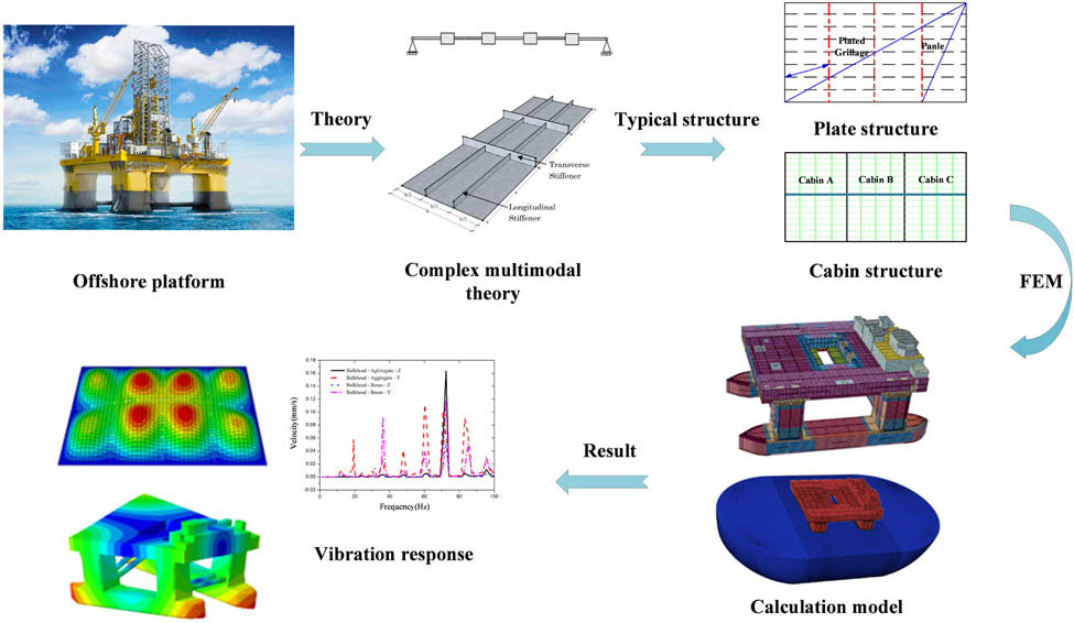
The vibration and noise performance of the offshore platforms are significant factors affecting the comfort and physical and mental health of the staff, and are also important indicators for evaluating the status of platforms. Based on the principle of structural dynamics, taking the semi-submersible platform as the research object, this article systematically and comprehensively studies the vibration characteristics and transfer laws of some partial-frame structures to the overall structure by combing theoretical derivation and numerical simulation. Firstly, the coupling dynamic model of the device-plate-platform is established, and the vibration transmission from the excitation source to the platform structure through the coupling system is analyzed theoretically. Secondly, the multimodal vibration mechanism of the plate frame and cabin structure is discussed by considering the plate frame and the plate frame as one. Finally, based on the semi-submersible platform structure, the study of complex multi-modal vibration transfer law of platform structure is carried out, which contributes to the research on multimodal coupled vibration protection of offshore platform structure.
Graphical abstract
1 Introduction
With the proposal of the green environmental protection design concept, the influence of long-term use of the vibration and noise levels of marine equipment on crew health is receiving increasing attention. Therefore, the current vibration and noise reduction technology has become a major contradiction in the design of high-end offshore platforms, and it is also the core technology of the competitive development of various maritime powers. The offshore platform structure is composed of a large number of plate structures. The plate structure is an important part to ensure the mechanical performance of the platform structure, and it is also one of the main factors affecting the vibration transmission of the platform. However, the slab structure has the coupling vibration problem of beam and plate structure, the overall structure vibration of the platform has the coupling vibration problem of local vibration and overall vibration, and the structure form is complex. Therefore, the research is carried out from simple to complex, from a single structure to a coupled system.
1.1 Research on vibration characteristics of the plate frame
For the slab and plate frame structure, the plate frame can be regarded as the coupling between the slab and the beam structure, and it can also be regarded as the loading of certain boundary conditions at the corresponding position of the slab. Therefore, the slab and the plate frame are the same in terms of analysis theory, calculation, and solution, and are collectively called plate structure here. The study of plate structure vibration has a history of more than 200 years, and many theories have been formed, including classical plate theory [1], first-order shear deformation theory (FSDT) [2,3,4,5], high-order shear deformation theory (HSDT) [6,7], and three-dimensional elastic theory.
Classical plate theory is based on Kirchhoff-Love’s “straight normal” assumption, which ignores the transverse shear strain of the structure, and can handle the thin plate problem well [8]. On the basis of the Kirchhoff plate model and the Euler beam model, Lin [9] studied the dynamic response of stiffened plates with different boundary conditions by theoretical and experimental methods. Wang et al. [10] used the modal superposition method to study the vibration and acoustic radiation responses of a finite-size rectangular stiffened plate with decoupling layers based on the Kirchhoff plate model and the Euler beam model, and the results reflected that the shear wave has a significant effect on the low-frequency vibration level difference of the stiffened plate. Gao et al. [11,12] based on Kirchhoff’s theory, considering the four degrees of freedom of stiffened ribs, established a theoretical model of the stiffened plate, and discussed the relationship between the free vibration and forced vibration of ribs. Du et al. [13–15] studied a unified method for free and forced vibration of stiffened plates without angles under classical and elastic boundary conditions. Mu et al. [16] studied the dynamic response of foam sandwich panels under time-independent impact loads based on the stepped sandwich plate model. In this model, the Kirchhoff plate theory is used for the panel, and the first-order or second-order shear theory is used for the sandwich layer. The results show that the gradient foam sandwich panel has a better vibration absorption effect than the uniform foam sandwich panel.
The FSDT and the higher-order shear deformation theory assume that the transverse shear strain of the elastic body is distributed along the thickness direction according to a certain law, and the solution accuracy is higher. On the basis of FSDT, Abedi et al. [17] deduced the governing differential equations and boundary condition equations of rectangular composite laminates with common adhesion and arbitrary boundary conditions. On the basis of FSDT, Ye et al. [18] studied the free vibration problem of thick composite laminates with general boundary by using the improved Fourier solution. In this model, the displacement and rotation angle of the plate is expressed by the new triangular series expansion. On the basis of FSDT, Pang et al. [19,20,21,22] used the penalty parameter method to obtain the boundary conditions. The free vibration of the composite laminated shell was analyzed by the Rayleigh–Ritz method, and the convergence study and numerical verification were carried out. Jin et al. [23] used the improved Fourier–Ritz method, which is improved based on Reddy’s high-order shear theory, to establish a vibration equation of sandwich beams with different boundary conditions of laminated panels and viscoelastic sandwich layers. The model takes into account the effects of bending–stretching coupling, bending–torsion coupling, stretching–torsion coupling, and Poisson’s ratio. On the basis of Reddy’s HSDT, Marjanovi and Nefovska-Danilovic [24,25] established the dynamic stiffness matrix of rectangular multilayer plate elements with free boundaries. By introducing the boundary layer equation, three coupled Euler–Lagrange equations in the model are transformed into two uncoupled equations, so that the established model can analyze the transverse free vibration of laminated plates with different boundary conditions. Nguyen et al. [26] established a new HSDT to study the free vibration and buckling characteristics of sandwich beams with functionally graded materials. The correctness of the theory is verified by comparing with the existing high-order shear model.
1.2 Research on vibration characteristics of platform structure
For the platform structure, Xu et al. [27] introduced the tuned inertial damper into the offshore platform as a passive control device, transforming the original multidegree-of-freedom system into a single-degree-of-freedom modal system, thereby reducing the excessive vibration of the platform structure caused by wave and seismic loads. Tang et al. [28] studied the vibration characteristics of typical raft structures based on acoustic black holes. Studies suggested that the optimal value of the main parameters of the acoustic black hole is applied to the raft structure, which can significantly reduce the average vibration response peak of the raft structure. In particular, the vibration acceleration level in the frequency domain above 500 Hz is reduced by about 10 dB. Wang et al. [29] studied the stiffened plate under multisupport excitation, verified the effectiveness of the coherency design method of dynamic vibration absorption optimization, and proposed a low-frequency multiline spectral vibration control method for the local resonance region of offshore platforms. Leng et al. [30] proposed a vibration isolation system based on magnetorheological elastomer to control the vibration of offshore platforms. A semi-active fuzzy controller is used to realize real-time nonresonant vibration control, and its effectiveness is evaluated numerically. Su et al. [31] improved the structure of a drilling platform, established a coupling dynamic model, and studied the coupled vibration characteristics of the drilling platform under the combination of cyclic impact load, parallel wind load, and orthogonal wind load.
1.3 Research on structural vibration transmission characteristics
In the field of structural vibration transmission characteristics, a majority of scholars focus on the rational design of the base structure to reduce the vibration energy transmission of mechanical equipment. The input impedance of the base is an important acoustic design parameter of the equipment base, which determines the amount of vibration energy transmitted to the platform structure. Increasing the input impedance of the base structure is a more effective measure to achieve structural vibration control. Therefore, it is necessary to clarify the correlation of the base structure impedance. The influencing factors and the influence degree of each factor can provide theoretical support for designers to optimize the coupling vibration energy transfer characteristics between the equipment and the base. In this regard, foreign scholars’ research started earlier. Ding et al. [32] analyzed the influence of different forms of base structures on the vibration and sound radiation characteristics of ships. His research showed that the base structure with uniform force transmission can effectively control the hull vibration. Tian et al. [33] studied the input energy, distribution, transmission, and vibration characteristics of the structural strength of the base, which provided a basis for the structural design of the platform base. Wang et al. [34] carried out an approximate calculation of the vibration and acoustic radiation of the blocking mass-plate structure. The structural vibration was approximated by the finite element method (FEM), while the sound field and structural surface were approximated by the boundary element method of the Helmholtz equation. The influence of the structural parameters of the blocking mass on the vibration and acoustic radiation was obtained.
Experts and scholars have carried out a lot of research on the vibration characteristics of typical structures such as beams and frames, carried out theoretical derivation of structural vibration, and carried out numerical simulation based on the modal superposition theory [35,36] and the finite element analysis [37]. Limited by the difference in ship form characteristics, there are few studies on the vibration characteristics of offshore platform structures. This research focuses on the typical and overall structure of the semi-submersible platform, and reveals the vibration transmission and attenuation mechanism of the equipment–base–platform coupling system. Based on the real ship test inversion excitation data, the influence analysis of the vibration characteristics of the typical structure of the platform is carried out, which can provide effective support for the vibration control of the platform structure.
2 Theoretical equations
Power equipment is widely used in the fields of ships and marine engineering, and the periodic vibration load generated during its operation is the main source of vibration and noise in marine structures. The equipment vibration response is transmitted to the platform structure through the equipment–base–platform coupling vibration system, which hurts the structural safety, personnel comfort, equipment service life, and accuracy of the offshore platform. The basic theory of vibration transmission of offshore platforms is deduced as follows.
The equipment-based platform coupling dynamic model is simplified and established as a multidegree-of-freedom vibration system. The systematic damping is simplified as proportional damping, and then the differential equation of forced vibration with damping is expressed as follows:
where
From Fourier transform into Eq. (1), the following formula can be obtained:
By introducing displacement impedance, Eq. (2) can be rewritten as follows:
where
According to the vibration theory, the response of any point in a multidegree-of-freedom vibration system can be expressed as a linear combination of each modal. Assuming that the system is an N-degree-of-freedom system, the response at any point l in the vibration system can be expressed as follows:
where
The modal matrix composed of modal vectors of each order can be expressed as follows:
From Eqs. (5) and (7), the response of the multidegree-of-freedom vibration system is expressed as follows:
where
Arrange the aforementioned to obtianed the following:
The mass matrix and stiffness matrix in Eq. (10) satisfy the following orthogonality conditions:
According to the aforementioned description, the damping of the multidegree-of-freedom vibration system is assumed to be Rayleigh damping and satisfies the following equation:
where,
For Eq. (13), the decoupling condition needs to be satisfied to establish the following orthogonal conditions are established.
where
Assume that:
For Eq. (13), multiplying the left side by
As suggested by Eq. (18), any r-order modal must have the following relation.
where
Meanwhile, Eq. (19) can be rewritten as follows:
where
The vibration displacement of point l of a multidegree-of-freedom vibration system is given as follows:
For the equipment–base–platform coupling system, it may be assumed that the base is point P, and the excitation force acts directly on point P. When the excitation force is a single-point excitation, it has the following matrix form:
Then the modal force can be expressed as follows:
According to the aforementioned formula, Eq. (21) can be rewritten as follows:
By substituting Eq. (26) into Eq. (23), we obtain the displacement at point l of the multidegree-of-freedom vibration system.
Since point l is any point on the platform structure, it is assumed that the vibration response assessment point of the platform structure is also point l. The transfer characteristic between the excitation force of the equipment and the displacement of any point of the platform structure can be expressed as follows:
where
According to the relationship among displacement, velocity, and acceleration, it can obtain the transfer function between the excitation force of the equipment and the velocity and acceleration of any point of the platform structure. Thus, the vibration response of the platform structure is obtained, including displacement, velocity, and acceleration.
Equation (26) describes the transfer relationship between the vibration displacement of any point of the platform and the excitation force of the equipment. However, due to the complexity of the real environment on the platform, it is difficult to obtain the accurate excitation force of the equipment, but the vibration acceleration at the equipment base panel is more convenient to obtain. Therefore, the vibration response of equipment base panels is generally measured in practical engineering applications. The transfer function of the base vibration acceleration under the equipment excitation to the hull surface vibration velocity response is given in the following text.
From Eq. (26) and the relationship between vibration displacement and vibration velocity, the vibration velocity at point of the platform structure can be expressed as follows:
According to the relationship between the vibration displacement response and the vibration velocity response, the vibration acceleration response of point P is expressed as follows:
According to Eqs. (29) and (30), the transfer characteristic function between the vibration acceleration of point p and the point l of the platform can be expressed as follows:
where
3 Numerical results and discussion
The aforementioned theoretical research will be applied to carry out numerical simulation in this section. Based on the finite element software ABAQUS, a numerical simulation environment is built to study the vibration characteristics of the overall structure of the plate frame, cabin, and offshore platform. The FEM used in this research is a common method for structural vibration analysis, which has been widely recognized in the industry, and its effectiveness verification process is not described in this article.
3.1 Research on vibration transmission characteristics of typical local plate frame structures
The plate frame structure is a significant part of the offshore platform and is also an important structure to transfer the periodic load of equipment. Taking the plate frame structure as the research object, as shown in Figure 1, the vibration transfer characteristics of the typical plate frame structure are studied. Among them, the plate length L = 14,400 mm, the plate width B = 7,560 mm, the cross-sectional size of the beam is T400 × 8/200 × 10, the cross-sectional size of the longitudinal beam is HP120 × 7, and the plate frame structure adopts ship steel materials with E = 2.1 × 10¹¹ Pa, ρ = 7,850 kg/m3, and ν = 0.3. Set excitation points and checkpoints at the beam, aggregate, and plate structures.
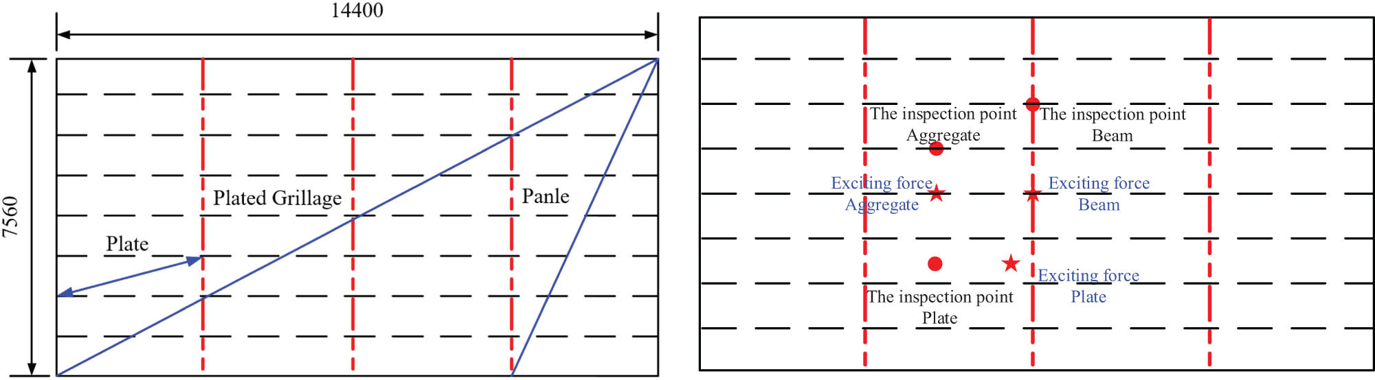
Schematic diagram of the plate frame structure model.
3.1.1 Comparative analysis of vibration response under different loads
Vertical unit force and periodic equipment load are separately applied to the center of the plate frame structure to analyze the vibration transfer characteristics of the plate frame structure. Based on the previous vibration test results of ship machinery equipment, the periodic excitation force generated by the equipment is inverted by iterative calculation. The periodic load of equipment is shown in Figure 2, and the initial excitation frequency is 12 Hz.

Equipment periodic input load.
The excitation is applied at the center position of the beam, and the results of extracting the vibration velocity response at the position of the typical beam, aggregate, and plate in the plate frame structure are shown in Figure 3. Figure 3(a) shows the vibration velocity response curve under unit force load, and it is found that there are clear peaks at 13.6, 16.4, 31.5, 53.6, and 79.2 Hz. Figure 3(b) shows the vibration velocity response curve under periodic force load. The frequencies corresponding to the peak velocity include the odd-order frequency of the plate frame mode and the peak frequency of the excitation source load, and the vibration peak is more evident at the frequency corresponding to the peak load. The peak frequency of the initial modal frequency of the plate frame is much higher than other frequency values, so the initial inherent frequency of the structure is designed to be higher than the frequency of the general excitation force in a certain range, to avoid resonance and improve the stiffness and reduce the vibration response value.

Vibration velocity response curve of the deck panel structure. (a) Unit force load. (b) Periodic force load.
3.1.2 Comparative analysis of vibration response at different loading positions
Periodic vertical excitation is applied at the load position of the longitudinal aggregate and beam, as well as at the center of the plate. The vibration velocity response result is shown in Figure 4. It can be seen from the figure that, first, when the load is applied to the position of the aggregate and the plate, the vibration response spectrum is tantamount to the peak frequency when the load is applied to the beam, which is mainly the peak frequency of the excitation load, but the vibration response trend at each peak frequency is different. Second, when the loading position is at the peak position of the local or overall mode shape, and the test point is at the peak position of the mode shape, the vibration response also shows evident peak values, such as the frequency of 13.6 and 70.7 Hz. Third, the structure resonates when the excitation frequency is close to the inherent frequency of the structure and the loading position is at the peak position of the vibration mode for the plate and frame structure. As is shown, the velocity response value at 36.1 Hz is much higher than other peaks.
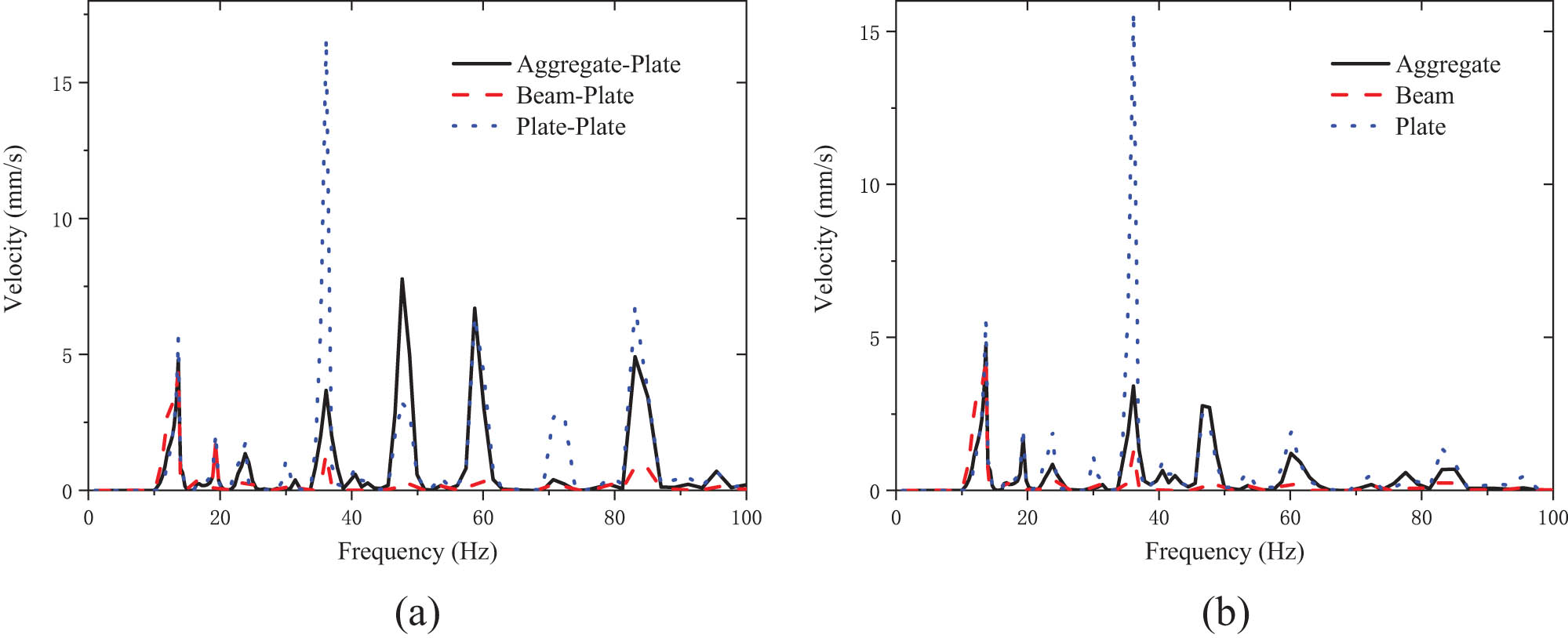
Vibration velocity response curve at different loading positions. (a) Excitation force applied to the plate. (b) Excitation force applied to aggregate.
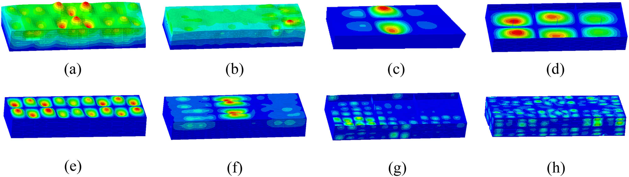
Combining Figures 3(b) and 5, the frequencies corresponding to the extreme vibration response are 13.6 and 36.1 Hz. The vibration responses corresponding to these two frequencies under different load positions are analyzed. At the same time, as far as the results of calculation and analysis are concerned, the structural vibration mode changes under different excitation positions. With vibration velocity as the assessment index, the peak value of structural vibration is also different under the excitation of periodic load. As shown in Figure 5, the vibration response value of the plate frame structure is the smallest when the load acts on the beam with high rigidity, followed by the stiffener, and the plate is the largest, and the vibration response cloud map corresponds to the modal vibration mode. When the frequency is 36.1 Hz, the peak response value of the structure applied to the aggregate and plate is significantly higher than that applied to the beam, and the resonance is generated at the plate and the frame structure. The excitation point of the beam is at the node position of the mode shape, and the response peak value does not appear even when the vibration is resonant.
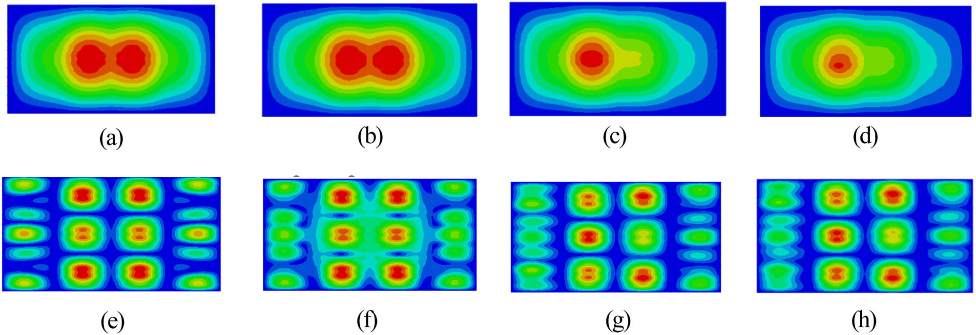
Vibration response cloud map of peak frequency mode at different loading positions. (a) Mode-13.6 Hz, (b) load acts on beam response peak-6.4 mm·s−1, (c) load acts on aggregate response peak-8.7 mm·s−1, (d) load acts on plate response peak-9.6 mm·s−1, (e) mode-36.1 Hz, (f) load acts on beam response peak-1.9 mm·s−1, (g) load acts on aggregate response peak-21.7 mm·s−1, and (h) load acts on plate response peak-22.5 mm·s−1.
3.2 Research on vibration transfer characteristics in local high vibration response region
The vibration of the offshore platform structure is transmitted to each deck by the plate frame structures where the excitation source is located through the bulkhead. Due to the excitation source and its structural characteristics, there are some areas beyond the requirements of vibration design standards in some areas, which are defined as high vibration areas. To study the structural transfer characteristics in high vibration areas, a cabin structure of the superstructure of an offshore platform is taken as the research object to establish a vibration analysis model. The structural model information is as follows: the thickness of the structural plate is t = 8 mm; the longitudinal truss section size is T600 × 12/300 × 25; the beam section size is T400 × 8/200 × 10; the longitudinal beam section size is HP160 × 7; the height of the bulkhead is 3,300 mm, and the center of the cabin is provided with a column ϕ141 × 9.5 mm. As shown in Figure 6, the simply supported constraint is applied to the lower bulkhead boundary of the target deck.

Schematic diagram of cabin structure. (a) Deck aggregates and (b) bulkhead stiffener.
3.2.1 Research on free vibration characteristics of the platform structure
The vibration mode analysis of the aforementioned cabin model is conducted, and the modal frequency within 100 Hz is shown in Figure 7. The mode order is about 600, and the change of frequency value decreases with the increase of the order, because when the order increases, the number of mode nodes also increases accordingly. There are a large number of local modes in each structure interval and their frequency values are relatively close.

Modal frequency variation within 100 Hz.
The generalized mass values of different modal orders are obtained by calculating the free vibration of the structure. As shown in Figure 8, the generalized mass has arresting peaks at mode 46 and mode 67. Compared with the mode shape diagram, the two-order frequency corresponds to the lateral and longitudinal modes of the structure, as shown in Figure 9(a) and (b); Figure 9(c) shows the initial vibration mode of the model, and the peak value is shown as the local vibration mode of the roof of the cabin B. Compared with Figure 9(d), the initial vibration mode of the bottom deck appears in cabin A. Figure 9(c) and (d) shows the coupling of the local vibration mode of each bulkhead segmentation interval and the overall vibration mode of the deck. Figure 9(e)–(h) lists the mode shape corresponding to the peak frequency of the preloaded excitation load and gradually presents the slab structure, the multinode vibration mode of the plate frame, the multinode vibration mode of the slab, and the vibration mode of the plate as the frequency increases.

The relationship between modal order and generalized mass.
Mode shape diagram of superstructure structure. (a) f = 29.7 Hz, (b) f = 37.1 Hz, (c) f = 11.6 Hz, (d) f = 13.8 Hz, (e) f = 24 Hz, (f) f = 36 Hz, (g) f = 48 Hz, and (h) f = 72 Hz.
In summary, for the typical cabin structure, the natural modal properties of the structure include the vibration mode of the whole model, the vibration mode of the local plate frame structure, the vibration mode of the slab and the vibration mode of the plate, and the local vibration modes reflect the coupling characteristics with the overall vibration modes to various degrees.
3.2.2 Research on vibration transmission characteristics of the platform structure
Considering the structural characteristics of the cabin, cabin A and cabin C show symmetrical characteristics about cabin B, so the assessment points are only set in cabin A and cabin B. As shown in Figure 10, the central beam of the bulkhead in the two cabins and the aggregate between the beam and the boundary are selected as the assessment points. The assessment point of the cabin roof corresponds to the floor, and the excitation point is set at the junction of the aggregate in cabin B.
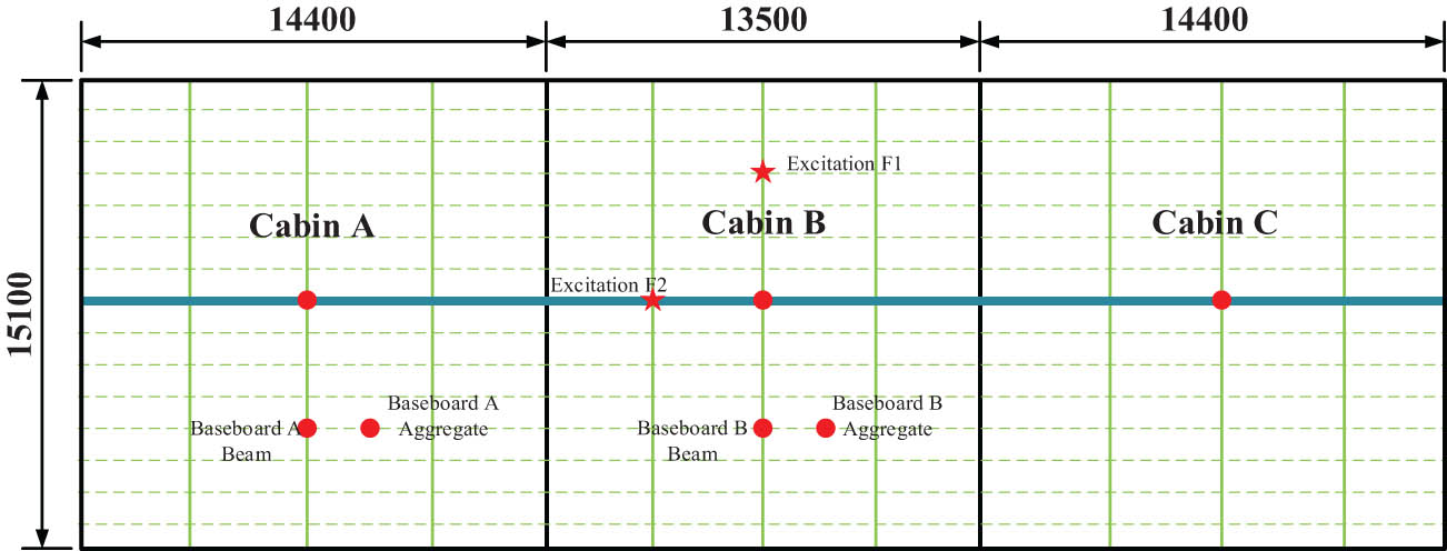
Schematic diagram of excitation position.
The cabin vibration response results are shown in Figure 11. As shown in Figure 11(a) and (b), the peak vibration frequency of the floor and roof structure is close to 12, 60, and 72 Hz. Due to the position where the excitation load is applied, small vibration peaks occur at frequencies of 14.4 and 18 Hz, which are the peak positions of local vibration modes. Figure 11(c) shows the vibration response value of the assessment point in the bulkhead in the vertical direction and the transverse direction with a large amplitude of the bulkhead. Comparing Figure 11(a) and (b), it is found that the peak value acting on the bottom plate is about 2.5 mm·s−1, while it is about 1.8 mm·s−1 on the desk position, and that of the bulkhead assessment point is approximately 0.18 mm·s−1, which is much lower than the deck position. It can be considered that the vibration load is less attenuated by the vibration of the bulkhead, and the deck vibration response is the main way.
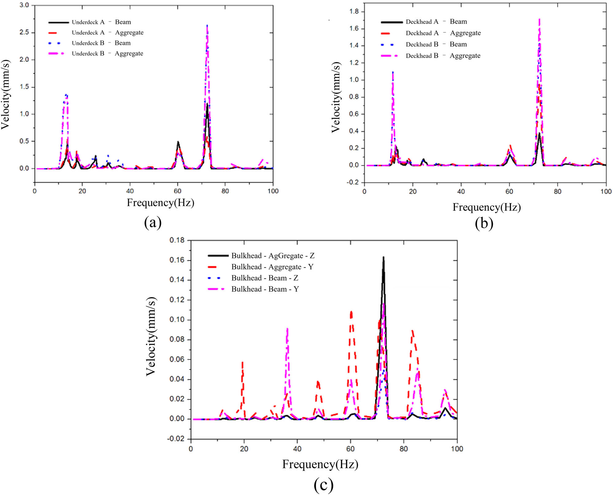
Comparing graph of the vibration response curve of cabin structure. (a) Underdeck, (b) deckhead, and (c) bulkhead.
To better analyze the relationship between vibration response law and mode shape, Figure 12 lists the corresponding vibration modes and vibration response cloud images with peak frequencies of 11.6 and 72.3 Hz. It can be seen from the figure comparison that the trend of the vibration velocity cloud map on each deck is the same as that of the vibration mode shape regardless of the low-order integral coupled mode shape or the high-order local mode shape. Influenced by the loading position, the vibration response value near the loading area of the bottom deck is relatively higher than that of other areas.
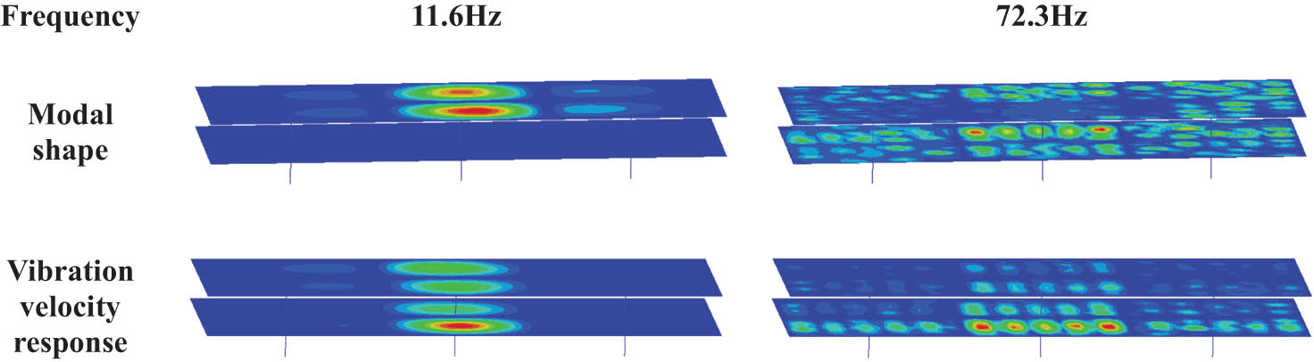
Vibration mode and vibration velocity response contour.
3.3 Research on vibration characteristics of semi-submersible offshore platform
In semi-submersible drilling platform, as a large-scale deep-water Marine equipment, vibration is mainly induced by the comprehensive action of major vibration sources such as propulsion system, power machinery, drilling system, air conditioning, and ventilation system. The vibration forms are complex, while the influencing factors are diverse. ABAQUS software was used to establish the offshore platform model. Due to the large size of the main structure of the platform, shell elements were used in the calculation model, shell elements and beam elements were combined in the model of the strong beam and truss structure, and beam elements were used in the structure of the ribs and small supporting materials, and rod elements were used in the linear members such as the pillars, and acoustic tetrahedral elements were used in the fluid domain. When the geometric model is divided into grids, the mesh cell size
For the finite element analysis of large-scale structures, in addition to meeting the requirements of the aforementioned mesh size, it is also necessary to analyze the mesh independence of the finite element model. Therefore, this study takes the first three natural frequencies of the structure as the assessment index, sets the initial value of the grid size to 1.0 m, and gradually refines the grid to carry out the grid independence analysis. The results are shown in Table 1.
Element size verification
| Element size | 1.0 m | 0.8 m | 0.6 m | 0.4 m |
|---|---|---|---|---|
| Element number | 183899 | 266145 | 407786 | 800237 |
| First mode | 1.17 Hz | 0.92 Hz | 0.71 Hz | 0.70 Hz |
| Second mode | 2.33 Hz | 1.88 Hz | 1.63 Hz | 1.64 Hz |
| Third mode | 2.45 Hz | 2.01 Hz | 1.78 Hz | 1.76 Hz |
What can we find in Table 1 is that as the element size decreases, the calculation results of the natural frequency of the structure gradually approach. Especially when the 0.6 m mesh is refined to 0.4 m, the calculation results of the natural frequency of the structure are almost the same, but the number of elements of the finite element model will increase greatly, and the cost of calculation will also increase. Therefore, the significance of further refinement of the grid here is not significant.
Finally, the finite element convergence mesh scale is determined to be 0.6 m. The finite element model of offshore platform structure contains 407,786 elements, including 142,965 beam elements and 264,821 shell elements. The Figure 13 shows the vibration characteristic analysis model of the semi-submersible offshore platform.
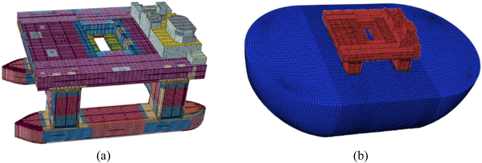
Global vibration analysis model of semi-submersible platform. (a) Geometric model of the semi-submersible drilling platform and (b) fluid–solid coupled model.
It indicates that the main equipment causing the overall vibration of the platform and contributing to the structural vibration is the diesel generator set, DP push press, and drilling mud pump. These devices generate periodic excitation loads during operation and are the primary vibration sources of the semi-submersible platform. The diesel generator set is centrally arranged in the tail of the deck box, the mud pump is centrally arranged in the middle part of the ship, and the DP thruster is distributed in the bow, middle, and tail of the two pontoons. The vibration characteristics of the semi-submersible platform are analyzed by using the test data that have the same specification with the input load.
3.3.1 Free vibration characteristic analysis of semi-submersible platform
Figure 14 shows the vibration mode diagram of the first eight modal frequencies of the platform. The semi-submersible platform is a three-dimensional structure, and the overall mode shape is more complex than the ship structure. The mode shape includes torsion, bending, and the coupling of the two. The direction covers the vertical, longitudinal, and transverse. At the same time, the lower hull, the overall mode shape, and the local mode shape of the buoy and the column have a coupling mode shape because of the structural characteristics of the lower hull. Due to the complexity of the semi-submersible platform structure, the transmission of its vibration response is relatively more complicated. The vibration characteristics of the semi-submersible platform structure are pursued further in combination with the vibration response analysis.

Semi-submersible rig global modal. (a) f = 0.71 Hz, (b) f = 1.63 Hz, (c) f = 1.78 Hz, (d) f = 2.12 Hz, (e) f = 2.44 Hz, (f) f = 2.49 Hz, (g) f = 2.52 Hz, and (h) f = 2.59 Hz.
3.3.2 Overall vibration response characteristics analysis of semi-submersible platform structure
According to the aforementioned research, the structural vibration mode is gradually complex with the increase of the inherent frequency of the structure. Figure 15 shows the overall structural vibration response cloud column. Figure 15(a) shows the frequency response cloud map of the corresponding frequency of the global vertical bending mode of the structure, while Figure 15(b) shows the frequency response cloud map of the push machine blade frequency, and Figure 15(c) shows the response cloud map of the dominant engine ignition frequency. Comparing Figure 15(a)–(c) shows that with the increase of frequency, the structural vibration response also gradually presents the local structural vibration of complex high nodes from the trend of low-order single overall vibration response. The vibration response is much higher than other frequencies at the excitation frequency, and the frequency response contribution of low-order excitation frequency is relatively high. Figure 15(d) shows the peak of the vibration response cloud picture of the overall platform structure. The comparison reflects that for the structural area far from the excitation source, the vibration peak corresponds to the response cloud map of the propeller blade frequency. The spectrum characteristics of load near the main engine and mud pump are complex, and their spectrum characteristics are consistent with the spectrum characteristics of the equipment itself.
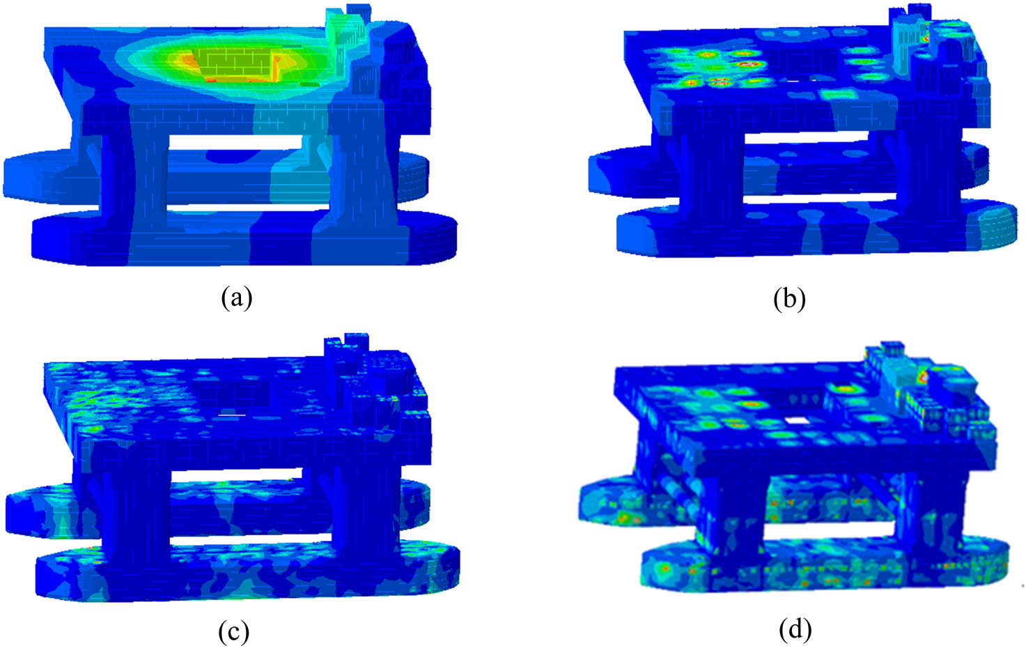
Contours of global structure vibration response of semi-submersible drilling platform. (a) f = 2.5 Hz, (b) f = 10.7 Hz, (c) f = 72 Hz, and (d) peak vibration response of the overall structure of the platform.
3.3.3 Vibration response characteristics analysis of platform deck box structure of semi-submersible
The deck box is divided by the transverse and longitudinal bulkheads. The bow is mainly the living area, while the midship and stern serve as the mechanical areas. For the convenience of vibration identification, the deck hold is divided into three sections: bow, midship, and stern, and five sections: port, port-middle, midship, starboard-middle, and starboard.
By analyzing the frequency response curve of the deck box area, as shown in the Figure 16, it can be seen that for the whole deck box structure, the peak response of the bow region and midship region mainly focuses on the corresponding frequency of propeller blade frequency and polyploid blade frequency. The midship has peak values at the first frequency of the dominating engine and the second stroke frequency of the mud pump. The frequency response amplitude of the midship region is lower than that of the propeller blade. For the whole frequency band of the aft region and the bottom midship region, the deck has multiorder frequency response amplitudes because the aft is close to the main engine and the structure around the excitation source presents multiorder frequency response amplitudes of the main engine. The load transfer of the mud pump is evident through the midship section of the bottom deck. The structure reflects the frequency response amplitude of the multistage mud pump in this area.

Spectrum diagram of vibration acceleration response of deck box structure. (a) Bow of the main deck, (b) midship of the main deck, (c) stern of the main deck, (d) bow of the middeck, (e) midship of the middeck, (f) stern of the middeck, (g) bow of the bottom deck, (h) midship of the bottom deck, (i) stern of the bottom deck, and (j) bow of the double bottom deck.
Furthermore, the vibration characteristics of the deck box structure corresponding to the propeller blade frequency of 10.7 Hz are analyzed, as shown in Figure 17(a), and the structural vibration is global vibration and local coupled vibration. In terms of overall vibration, the global vibration response trend of each deck is consistent with the frequency mode shape, and the vibration response of the bottom deck is relatively low due to the double-bottom structure design. In matters of local vibration, the local peak occurs in the local deck area due to relatively low structural stiffness, as shown in the gray area in Figure 17(b). To further analyze the correlation between structural response and mode, Figure 18 compares the corresponding vibration response spectrum map and mode shape diagram of the bottom deck structure at the peak frequencies of the three dominating excitation sources in detail. It is found that the vibration response at each typical frequency is corresponding to the mode shape near the frequency. The difference is that the vibration response of the structure near the excitation source will appear at the peak frequency of the excitation source.
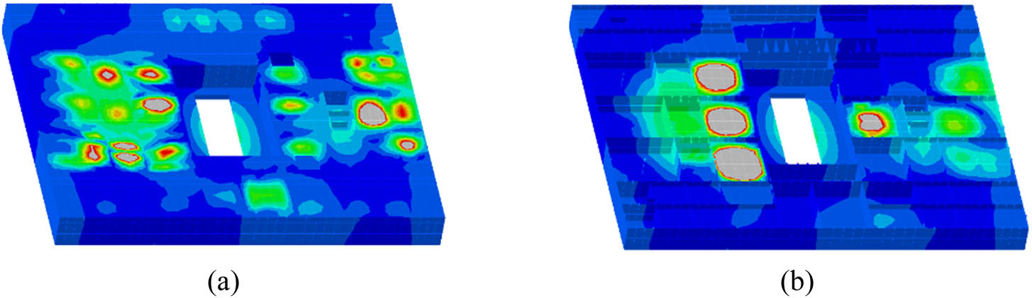
Deck box structure vibration response cloud picture f = 10.7 Hz. (a) Overall view and (b) section view.

Contrast cloud picture of vibration response and mode of bottom deck excitation frequency. (a0) f = 9.96 Hz, (b0) f = 10.7 Hz, and (c0) f = 11.9 Hz, and (a1) f = 9.98 Hz, (b1) f = 10.7 Hz, and (c1) f = 11.9 Hz.
4 Conclusion
In this research, the semi-submersible offshore platform is taken as the research object, focusing on the vibration characteristics of the plate frame, deck box, and the overall structure. Considering the coupling effect between the equipment–base–platform, the vibration transmission and attenuation characteristics of the structure are deduced in detail. The coupling mechanism between the components is revealed, and the internal relationship between the external excitation and any point of the complex structure is established. Based on the aforementioned theory, this study analyzed the dynamic characteristics of the structure from the perspective of modal vibration mode and vibration response, and drew the following conclusions:
The spectral characteristics of the external excitation, the applied position, and the natural frequency of the structure are closely related to the structural vibration characteristics. Increasing the local stiffness can effectively reduce the response peak.
For complex structures, the frequency response characteristics gradually increase with the increase of frequency, and there is a coupling relationship between the local mode and the overall mode, which is particularly obvious in the high-order modes of the structure under external excitation.
Acknowledgments
This research was supported by Harbin Engineering University.
-
Funding information: This study was funded by Development program of Shandong Province (2019JZZY010125).
-
Author contributions: All authors have accepted responsibility for the entire content of this manuscript and approved its submission.
-
Conflict of interest: The authors state no conflict of interest.
References
[1] Abualnour, M., M. S. A. Houari, and A. Tounsi. A novel quasi-3D trigonometric plate theory for free vibration analysis of advanced composite plates. Composite Structures, Vol. 184, 2018, pp. 688–697.10.1016/j.compstruct.2017.10.047Search in Google Scholar
[2] Shojaeefard, M. H., H. S. Googarchin, and M. Ghadiri. Micro temperature-dependent FG porous plate: Free vibration and thermal buckling analysis using modified couple stress theory with CPT and FSDT. Applied Mathematical Modelling, Vol. 50, 2017, pp. 633–655.10.1016/j.apm.2017.06.022Search in Google Scholar
[3] Liew, K. M., Y. Q. Huang, and J. N. Reddy. Vibration analysis of symmetrically laminated plates based FSDT using the moving least squares differential quadrature method. Computer Methods in Applied Mechanics and Engineering, Vol. 192, No. 19, 2003, pp. 2203–2222.10.1016/S0045-7825(03)00238-XSearch in Google Scholar
[4] Civalek, O. Free vibration analysis of symmetrically laminated composite plates with first-order shear deformation theory (FSDT) by discrete singular convolution method. Finite Elements in Analysis & Design, Vol. 44, No. 12–13, 2008, pp. 725–731.10.1016/j.finel.2008.04.001Search in Google Scholar
[5] Gao, C., F. Pang, and H. Li. Steady and transient vibration analysis of uniform and stepped annular/circular plates based on FSDT. Acta Mechanica, Vol. 233, No. 3, 2022, pp. 1061–1082.10.1007/s00707-022-03157-ySearch in Google Scholar
[6] Khiloun, M. B. A. A., A. Kaci, A. Bessaim, A. Tounsi, and S. R. Mahmoud. Analytical modeling of bending and vibration of thick advanced composite plates using a four-variable quasi 3D HSDT. Engineering with Computers, Vol. 36, No. 3, 2020, pp. 807–821.10.1007/s00366-019-00732-1Search in Google Scholar
[7] Kumar, A. and R. P. Shrivastava. Free vibration of square laminates with delamination around a central cutout using HSDT. Composite Structures, Vol. 70, No. 3, 2005, pp. 317–333.10.1016/j.compstruct.2004.08.040Search in Google Scholar
[8] Meier, C., A. Popp, and W. A. Wall. Geometrically exact finite element formulations for slender beams: Kirchhoff–Love theory versus Simo–Reissner theory, Springer, Netherlands, 2017.10.1007/s11831-017-9232-5Search in Google Scholar
[9] Lin, T. R. An analytical and experimental study of the vibration response of a clamped ribbed plate. Journal of Sound and Vibration, Vol. 331, No. 4, 2012, pp. 902–913.10.1016/j.jsv.2011.10.013Search in Google Scholar
[10] Wang, X., A. M. Zhang, and F. Pang. Noise reduction analysis for a stiffened finite plate. Journal of Sound and Vibration, Vol. 333, No. 1, 2014, pp. 228–245.10.1016/j.jsv.2013.08.043Search in Google Scholar
[11] Gao, C., H. Zhang, and H. Li. Numerical and experimental investigation of vibro-acoustic characteristics of a submerged stiffened cylindrical shell excited by a mechanical force. Ocean Engineering, Vol. 249, 2022, id. 110913.10.1016/j.oceaneng.2022.110913Search in Google Scholar
[12] Gao, C., F. Pang, and H. Li. A semi-analytical method for the dynamic characteristics of stiffened plate with general boundary conditions. Thin-Walled Structures, Vol. 178, 2022, id. 109513.10.1016/j.tws.2022.109513Search in Google Scholar
[13] Du, Y., F. Pang, and L. Sun. A unified formulation for dynamic behavior analysis of spherical cap with uniform and stepped thickness distribution under different edge constraints. Thin-Walled Structures, Vol. 146, 2020, id. 106445.10.1016/j.tws.2019.106445Search in Google Scholar
[14] Du, Y., L. Sun, and S. Li. Vibration analysis of truncated spherical shells under various edge constraints. Thin-Walled Structures, Vol. 147, 2020, id. 106544.10.1016/j.tws.2019.106544Search in Google Scholar
[15] Du, Y., D. Jia, and H. Li. A unified method to analyze free and forced vibration of stiffened plates under various edge conditions. European Journal of Mechanics - A/Solid, Vol. 9, 202, id. 10457.Search in Google Scholar
[16] Mu, L., D. Xiao, and C. Cho. Two-dimensional dynamic analysis of sandwich plates with gradient foam cores. Journal of Mechanical Science and Technology, Vol. 30, No. 9, 2016, pp. 4083–4093.10.1007/s12206-016-0821-2Search in Google Scholar
[17] Abedi, M., R.-A. Jafari-Talookolaei, and P. S. Valvo. A new solution method for free vibration analysis of rectangular laminated composite plates with general stacking sequences and edge restraints. Computers and Structures, Vol. 175, 2016, pp. 144–156.10.1016/j.compstruc.2016.07.007Search in Google Scholar
[18] Ye, T., G. Jin, and Z. Su. A modified Fourier solution for vibration analysis of moderately thick laminated plates with general boundary restraints and internal line supports. International Journal of Mechanical Sciences, Vol. 80, 2014, pp. 29–46.10.1016/j.ijmecsci.2014.01.001Search in Google Scholar
[19] Pang, F., H. Li, and H. Chen. Free vibration analysis of combined composite laminated cylindrical and spherical shells with arbitrary boundary conditions. Mechanics of Advanced Materials and Structures, Vol. 28, No. 2, 2021, pp. 182–199.10.1080/15376494.2018.1553258Search in Google Scholar
[20] Li, H., F. Pang, and X. Miao. Jacobi–Ritz method for free vibration analysis of uniform and stepped circular cylindrical shells with arbitrary boundary conditions: A unified formulation. Computers and Mathematics with Applications, Vol. 77, No. 2, 2019, pp. 427–440.10.1016/j.camwa.2018.09.046Search in Google Scholar
[21] Li, H., F. Pang, and H. Chen. A semi-analytical approach to analyze vibration characteristics of uniform and stepped annular-spherical shells with general boundary conditions. European Journal of Mechanics, A/Solids, Vol. 74, 2019, pp. 48–65.10.1016/j.euromechsol.2018.10.017Search in Google Scholar
[22] Li, H., F. Pang, and H. Chen. Vibration analysis of functionally graded porous cylindrical shell with arbitrary boundary restraints by using a semi analytical method. Composites Part B: Engineering, Vol. 164, 2019, pp. 249–264.10.1016/j.compositesb.2018.11.046Search in Google Scholar
[23] Jin, G., C. Yang, and Z. Liu. Vibration and damping analysis of sandwich viscoelastic-core beam using Reddy’s higher-order theory. Composite Structures, Vol. 140, 2016, pp. 390–409.10.1016/j.compstruct.2016.01.017Search in Google Scholar
[24] Marjanovi, M., N. Kolarevi, M. Nefovska-Danilovi, and M. Petronijević. Free vibration study of sandwich plates using a family of novel shear deformable dynamic stiffness elements: limitations and comparison with the finite element solutions. Thin-Walled Structures, Vol. 107, 2016, pp. 678–694.10.1016/j.tws.2016.08.002Search in Google Scholar
[25] Nefovska-Danilovic, M., N. Kolarevic, and M. Marjanović. Shear deformable dynamic stiffness elements for a free vibration analysis of composite plate assemblies–Part I: Theory. Composite Structures, Vol. 159, 2017, pp. 728–744.10.1016/j.compstruct.2016.09.022Search in Google Scholar
[26] Nguyen, T. K., T. T. P. Nguyen, T. P. Vo, and H. T. Thai. Vibration and buckling analysis of functionally graded sandwich beams by a new higher-order shear deformation theory. Composites Part B-Engineering, Vol. 76, 2015, pp. 273–285.10.1016/j.compositesb.2015.02.032Search in Google Scholar
[27] Xu, T., Y. Li, and D. Leng. Mitigating jacket offshore platform vibration under earthquake and ocean waves utilizing tuned inerter damper. Bulletin of Earthquake Engineering, 2022, pp. 1–24.10.1007/s10518-022-01378-zSearch in Google Scholar
[28] Tang, Y., J. Liu, and N. Liu. Dynamic characteristic analysis of acoustic black hole in typical raft structure. Reviews on Advanced Materials Science, Vol. 61, No. 1, 2022, pp. 458–476.10.1515/rams-2022-0038Search in Google Scholar
[29] Wang, N., Y. Du, and Q. Gong. Research on the low-frequency multiline spectrum vibration control of offshore platforms. Reviews on Advanced Materials Science, Vol. 61, No. 1, 2022, pp. 55–67.10.1515/rams-2021-0075Search in Google Scholar
[30] Leng, D., Z. Zhu, and K. Xu. Vibration control of jacket offshore platform through magnetorheological elastomer (MRE) based isolation system. Applied Ocean Research, Vol. 114, 2021, id. 102779.10.1016/j.apor.2021.102779Search in Google Scholar
[31] Su, R., H. Shen, and X. Liu. Analysis on coupling vibration characteristics of drilling frame-platform structure for open-pit down-the-hole drill. Yingyong Jichu yu Gongcheng Kexue Xuebao/Journal of Basic Science and Engineering, Vol. 26, No. 1, 2018, pp. 190–199.Search in Google Scholar
[32] Ding, K., Y.-S. Wang, and Y.-S. Wei. Influence of thrust bearing pedestal form on vibration and radiated noise of submarine. Chuan Bo Li Xue/Journal of Ship Mechanics, Vol. 17, No. 3, 2013, pp. 306–312.Search in Google Scholar
[33] Tian, X., G. Liu, and Z. Gao. Crack detection in offshore platform structure based on structural intensity approach. Journal of Sound and Vibration, Vol. 389, 2017, pp. 236–249.10.1016/j.jsv.2016.11.020Search in Google Scholar
[34] Wang, T., M. P. Sheng, and H. Wang. Band structures in two-dimensional phononic crystals with periodic S-shaped slot. Acoustics Australia, Vol. 43, No. 3, 2015, pp. 275–281.10.1007/s40857-015-0031-6Search in Google Scholar
[35] Pang, F., Y. Qin, and H. Li. Study on impact resistance of composite rocket launcher. Reviews on Advanced Materials Science, Vol. 60, No. 1, 2021, pp. 615–630.10.1515/rams-2021-0045Search in Google Scholar
[36] Guo, C., Z. T. Hui, and Y. U. Hong-Mei. Dynamic features analysis of magnetorheological composite beams on mode superposition method. Science Technology and Engineering, Vol. 19, No. 25, 2019, pp. 288–294.Search in Google Scholar
[37] Bao, Q. and H. Feng. Finite element simplified fatigue analysis method for a non-tubular joint of an offshore jacket platform. Journal of Marine Science and Application, Vol. 10, No. 3, 2011, pp. 321–324.10.1007/s11804-011-1075-0Search in Google Scholar
© 2023 the author(s), published by De Gruyter
This work is licensed under the Creative Commons Attribution 4.0 International License.
Articles in the same Issue
- Review Articles
- Progress in preparation and ablation resistance of ultra-high-temperature ceramics modified C/C composites for extreme environment
- Solar lighting systems applied in photocatalysis to treat pollutants – A review
- Technological advances in three-dimensional skin tissue engineering
- Hybrid magnesium matrix composites: A review of reinforcement philosophies, mechanical and tribological characteristics
- Application prospect of calcium peroxide nanoparticles in biomedical field
- Research progress on basalt fiber-based functionalized composites
- Evaluation of the properties and applications of FRP bars and anchors: A review
- A critical review on mechanical, durability, and microstructural properties of industrial by-product-based geopolymer composites
- Multifunctional engineered cementitious composites modified with nanomaterials and their applications: An overview
- Role of bioglass derivatives in tissue regeneration and repair: A review
- Research progress on properties of cement-based composites incorporating graphene oxide
- Properties of ultra-high performance concrete and conventional concrete with coal bottom ash as aggregate replacement and nanoadditives: A review
- A scientometric review of the literature on the incorporation of steel fibers in ultra-high-performance concrete with research mapping knowledge
- Weldability of high nitrogen steels: A review
- Application of waste recycle tire steel fibers as a construction material in concrete
- Wear properties of graphene-reinforced aluminium metal matrix composite: A review
- Experimental investigations of electrodeposited Zn–Ni, Zn–Co, and Ni–Cr–Co–based novel coatings on AA7075 substrate to ameliorate the mechanical, abrasion, morphological, and corrosion properties for automotive applications
- Research evolution on self-healing asphalt: A scientometric review for knowledge mapping
- Recent developments in the mechanical properties of hybrid fiber metal laminates in the automotive industry: A review
- A review of microscopic characterization and related properties of fiber-incorporated cement-based materials
- Comparison and review of classical and machine learning-based constitutive models for polymers used in aeronautical thermoplastic composites
- Gold nanoparticle-based strategies against SARS-CoV-2: A review
- Poly-ferric sulphate as superior coagulant: A review on preparation methods and properties
- A review on ceramic waste-based concrete: A step toward sustainable concrete
- Modification of the structure and properties of oxide layers on aluminium alloys: A review
- A review of magnetically driven swimming microrobots: Material selection, structure design, control method, and applications
- Polyimide–nickel nanocomposites fabrication, properties, and applications: A review
- Design and analysis of timber-concrete-based civil structures and its applications: A brief review
- Effect of fiber treatment on physical and mechanical properties of natural fiber-reinforced composites: A review
- Blending and functionalisation modification of 3D printed polylactic acid for fused deposition modeling
- A critical review on functionally graded ceramic materials for cutting tools: Current trends and future prospects
- Heme iron as potential iron fortifier for food application – characterization by material techniques
- An overview of the research trends on fiber-reinforced shotcrete for construction applications
- High-entropy alloys: A review of their performance as promising materials for hydrogen and molten salt storage
- Effect of the axial compression ratio on the seismic behavior of resilient concrete walls with concealed column stirrups
- Research Articles
- Effect of fiber orientation and elevated temperature on the mechanical properties of unidirectional continuous kenaf reinforced PLA composites
- Optimizing the ECAP processing parameters of pure Cu through experimental, finite element, and response surface approaches
- Study on the solidification property and mechanism of soft soil based on the industrial waste residue
- Preparation and photocatalytic degradation of Sulfamethoxazole by g-C3N4 nano composite samples
- Impact of thermal modification on color and chemical changes of African padauk, merbau, mahogany, and iroko wood species
- The evaluation of the mechanical properties of glass, kenaf, and honeycomb fiber-reinforced composite
- Evaluation of a novel steel box-soft body combination for bridge protection against ship collision
- Study on the uniaxial compression constitutive relationship of modified yellow mud from minority dwelling in western Sichuan, China
- Ultrasonic longitudinal torsion-assisted biotic bone drilling: An experimental study
- Green synthesis, characterizations, and antibacterial activity of silver nanoparticles from Themeda quadrivalvis, in conjugation with macrolide antibiotics against respiratory pathogens
- Performance analysis of WEDM during the machining of Inconel 690 miniature gear using RSM and ANN modeling approaches
- Biosynthesis of Ag/bentonite, ZnO/bentonite, and Ag/ZnO/bentonite nanocomposites by aqueous leaf extract of Hagenia abyssinica for antibacterial activities
- Eco-friendly MoS2/waste coconut oil nanofluid for machining of magnesium implants
- Silica and kaolin reinforced aluminum matrix composite for heat storage
- Optimal design of glazed hollow bead thermal insulation mortar containing fly ash and slag based on response surface methodology
- Hemp seed oil nanoemulsion with Sapindus saponins as a potential carrier for iron supplement and vitamin D
- A numerical study on thin film flow and heat transfer enhancement for copper nanoparticles dispersed in ethylene glycol
- Research on complex multimodal vibration characteristics of offshore platform
- Applicability of fractal models for characterising pore structure of hybrid basalt–polypropylene fibre-reinforced concrete
- Influence of sodium silicate to precursor ratio on mechanical properties and durability of the metakaolin/fly ash alkali-activated sustainable mortar using manufactured sand
- An experimental study of bending resistance of multi-size PFRC beams
- Characterization, biocompatibility, and optimization of electrospun SF/PCL composite nanofiber films
- Morphological classification method and data-driven estimation of the joint roughness coefficient by consideration of two-order asperity
- Prediction and simulation of mechanical properties of borophene-reinforced epoxy nanocomposites using molecular dynamics and FEA
- Nanoemulsions of essential oils stabilized with saponins exhibiting antibacterial and antioxidative properties
- Fabrication and performance analysis of sustainable municipal solid waste incineration fly ash alkali-activated acoustic barriers
- Electrostatic-spinning construction of HCNTs@Ti3C2T x MXenes hybrid aerogel microspheres for tunable microwave absorption
- Investigation of the mechanical properties, surface quality, and energy efficiency of a fused filament fabrication for PA6
- Experimental study on mechanical properties of coal gangue base geopolymer recycled aggregate concrete reinforced by steel fiber and nano-Al2O3
- Hybrid bio-fiber/bio-ceramic composite materials: Mechanical performance, thermal stability, and morphological analysis
- Experimental study on recycled steel fiber-reinforced concrete under repeated impact
- Effect of rare earth Nd on the microstructural transformation and mechanical properties of 7xxx series aluminum alloys
- Color match evaluation using instrumental method for three single-shade resin composites before and after in-office bleaching
- Exploring temperature-resilient recycled aggregate concrete with waste rubber: An experimental and multi-objective optimization analysis
- Study on aging mechanism of SBS/SBR compound-modified asphalt based on molecular dynamics
- Evolution of the pore structure of pumice aggregate concrete and the effect on compressive strength
- Effect of alkaline treatment time of fibers and microcrystalline cellulose addition on mechanical properties of unsaturated polyester composites reinforced by cantala fibers
- Optimization of eggshell particles to produce eco-friendly green fillers with bamboo reinforcement in organic friction materials
- An effective approach to improve microstructure and tribological properties of cold sprayed Al alloys
- Luminescence and temperature-sensing properties of Li+, Na+, or K+, Tm3+, and Yb3+ co-doped Bi2WO6 phosphors
- Effect of molybdenum tailings aggregate on mechanical properties of engineered cementitious composites and stirrup-confined ECC stub columns
- Experimental study on the seismic performance of short shear walls comprising cold-formed steel and high-strength reinforced concrete with concealed bracing
- Failure criteria and microstructure evolution mechanism of the alkali–silica reaction of concrete
- Mechanical, fracture-deformation, and tribology behavior of fillers-reinforced sisal fiber composites for lightweight automotive applications
- UV aging behavior evolution characterization of HALS-modified asphalt based on micro-morphological features
- Preparation of VO2/graphene/SiC film by water vapor oxidation
- A semi-empirical model for predicting carbonation depth of RAC under two-dimensional conditions
- Comparison of the physical properties of different polyimide nanocomposite films containing organoclays varying in alkyl chain lengths
- Effects of freeze–thaw cycles on micro and meso-structural characteristics and mechanical properties of porous asphalt mixtures
- Flexural performance of a new type of slightly curved arc HRB400 steel bars reinforced one-way concrete slabs
- Alkali-activated binder based on red mud with class F fly ash and ground granulated blast-furnace slag under ambient temperature
- Facile synthesis of g-C3N4 nanosheets for effective degradation of organic pollutants via ball milling
- DEM study on the loading rate effect of marble under different confining pressures
- Conductive and self-cleaning composite membranes from corn husk nanofiber embedded with inorganic fillers (TiO2, CaO, and eggshell) by sol–gel and casting processes for smart membrane applications
- Laser re-melting of modified multimodal Cr3C2–NiCr coatings by HVOF: Effect on the microstructure and anticorrosion properties
- Damage constitutive model of jointed rock mass considering structural features and load effect
- Thermosetting polymer composites: Manufacturing and properties study
- CSG compressive strength prediction based on LSTM and interpretable machine learning
- Axial compression behavior and stress–strain relationship of slurry-wrapping treatment recycled aggregate concrete-filled steel tube short columns
- Space-time evolution characteristics of loaded gas-bearing coal fractures based on industrial μCT
- Dual-biprism-based single-camera high-speed 3D-digital image correlation for deformation measurement on sandwich structures under low velocity impact
- Effects of cold deformation modes on microstructure uniformity and mechanical properties of large 2219 Al–Cu alloy rings
- Basalt fiber as natural reinforcement to improve the performance of ecological grouting slurry for the conservation of earthen sites
- Interaction of micro-fluid structure in a pressure-driven duct flow with a nearby placed current-carrying wire: A numerical investigation
- A simulation modeling methodology considering random multiple shots for shot peening process
- Optimization and characterization of composite modified asphalt with pyrolytic carbon black and chicken feather fiber
- Synthesis, characterization, and application of the novel nanomagnet adsorbent for the removal of Cr(vi) ions
- Multi-perspective structural integrity-based computational investigations on airframe of Gyrodyne-configured multi-rotor UAV through coupled CFD and FEA approaches for various lightweight sandwich composites and alloys
- Influence of PVA fibers on the durability of cementitious composites under the wet–heat–salt coupling environment
- Compressive behavior of BFRP-confined ceramsite concrete: An experimental study and stress–strain model
- Interval models for uncertainty analysis and degradation prediction of the mechanical properties of rubber
- Preparation of PVDF-HFP/CB/Ni nanocomposite films for piezoelectric energy harvesting
- Frost resistance and life prediction of recycled brick aggregate concrete with waste polypropylene fiber
- Synthetic leathers as a possible source of chemicals and odorous substances in indoor environment
- Mechanical properties of seawater volcanic scoria aggregate concrete-filled circular GFRP and stainless steel tubes under axial compression
- Effect of curved anchor impellers on power consumption and hydrodynamic parameters of yield stress fluids (Bingham–Papanastasiou model) in stirred tanks
- All-dielectric tunable zero-refractive index metamaterials based on phase change materials
- Influence of ultrasonication time on the various properties of alkaline-treated mango seed waste filler reinforced PVA biocomposite
- Research on key casting process of high-grade CNC machine tool bed nodular cast iron
- Latest research progress of SiCp/Al composite for electronic packaging
- Special Issue on 3D and 4D Printing of Advanced Functional Materials - Part I
- Molecular dynamics simulation on electrohydrodynamic atomization: Stable dripping mode by pre-load voltage
- Research progress of metal-based additive manufacturing in medical implants