Influence of cam profile errors in a modulator on the dynamic response of the heald frame
-
Honghuan Yin
 und
Weiye Zhang
und
Weiye Zhang

Abstract
This research endeavors to analyze the dynamic characteristics of the dobby, particularly the influence of a modulator on the dynamic response of the heald frame. By constructing precise kinematic and dynamic mathematical models and employing efficient computational algorithms, this study delves into the motion behavior of dobby. Component elastic deformation is considered, and a detailed analysis of the heald frame’s vibrational properties is conducted. With the establishment of dynamic and kinematic equations, coupled with Taylor series expansion and partial derivative techniques, the displacement errors were accurately calculated. The implementation of the fourth-order Runge–Kutta method facilitated numerical simulation, allowing for the analysis of the effect of cam profile errors on vibrational characteristics. The findings indicate that cam profile machining and system errors significantly influence the vibration amplitude under high-speed conditions. Consequently, this research highlights the imperative to control operating speeds in the design and operation of dobby and enhance vibration stability through precise machining of cam profiles, using high-precision equipment, and regular maintenance, which are essential for optimized design and improved stability and reliability.
1 Introduction
Within the realm of textile machinery, the dobby is a pivotal component whose dynamic characteristics critically influence the overall machine performance and fabric quality. The dynamic response and vibrational stability of such a mechanism are paramount in defining their performance, affecting the operational smoothness, precision, durability, and efficiency [1,2,3]. Despite the dynamic behavior of dobby being the subject of prior studies, the influence of flexible bodies and in-depth vibration analysis frequently remain unaddressed, leading to unforeseen problems in its applications.
This research aims to present an exhaustive analytical framework, particularly accentuating the impact of the modulator on the heald frame’s dynamic response within a dobby. The dynamic behavior of this mechanism is inherently complex and challenging to predict, more so when factoring in the deformation and vibrational attributes of flexible components [4,5,6]. Consequently, this research employs accurate and effective mathematical models and analytical methodologies to simulate and scrutinize the dynamic traits, especially the vibratory behavior of the heald frame. Commencing with the development of kinematic and dynamic mathematical models conducive to computational analysis, this study incorporates component elasticity and conducts an in-depth vibration characteristic examination. A heald frame vibration response model is meticulously formulated to assess the repercussions of cam profile inaccuracies on mechanical motion performance. Utilizing Taylor series expansions and fourth-order Runge–Kutta methods [7,8], the dynamic equations are approximated and resolved, affirming the precision of the outcomes.
The findings underscore the pronounced influence of cam profile errors on the dynamic properties of dobby, particularly under high-speed operations. The research, therefore, stresses the criticality of rigorous cam profile machining precision and the meticulous regulation of operating speeds during the design and operation phases of dobby. Additionally, the discourse advocates for the essentiality of regular maintenance and calibration in ensuring the machine’s longevity and consistent performance [9,10,11]. This study not only augments the comprehension of dobby dynamics but also endorses theoretical and pragmatic directives for design refinement, performance augmentation, and longevity enhancement.
2 Modulator – dynamics modeling and solution of the heald frame
2.1 Rotary variable speed mechanism – dynamics modeling of the gantry frame
System dynamics focuses on the analysis of intricate systems composed of various mechanisms, necessitating the development of kinematic and dynamic mathematical models apt for computational analysis to deliver precise and efficient solutions. Accurate emulation of the mechanical system’s movement requires the consideration of the effects of flexibility within the components on the system’s motion characteristics, as well as an analysis of their vibrational features [12,13].
The modulator must possess excellent mechanical performance to ensure that the dobby loom achieves high stability. Therefore, the motion characteristics of the modulator directly impact the weaving performance of the loom and the quality of the fabric. This mechanism converts the uniform circular motion input from the dobby motor into the vertical up-and-down motion of the heald frame, ensuring that the motion characteristics of the heald frame meet the requirements of the weaving process and guarantee the normal operation of the loom.
The working principle of the modulator is illustrated in Figure 1(a). In this mechanism, the conjugate cams (5 and 10) are fixed to the stationary housing of the dobby loom, while the cam swing arms (2 and 8) are hinged to the gear (1) and can rotate around their hinge points C and D. This allows the uniform circular motion input from the dobby motor shaft to be transmitted through the gear (1) to the cam rollers (3, 6, 9, and 12).
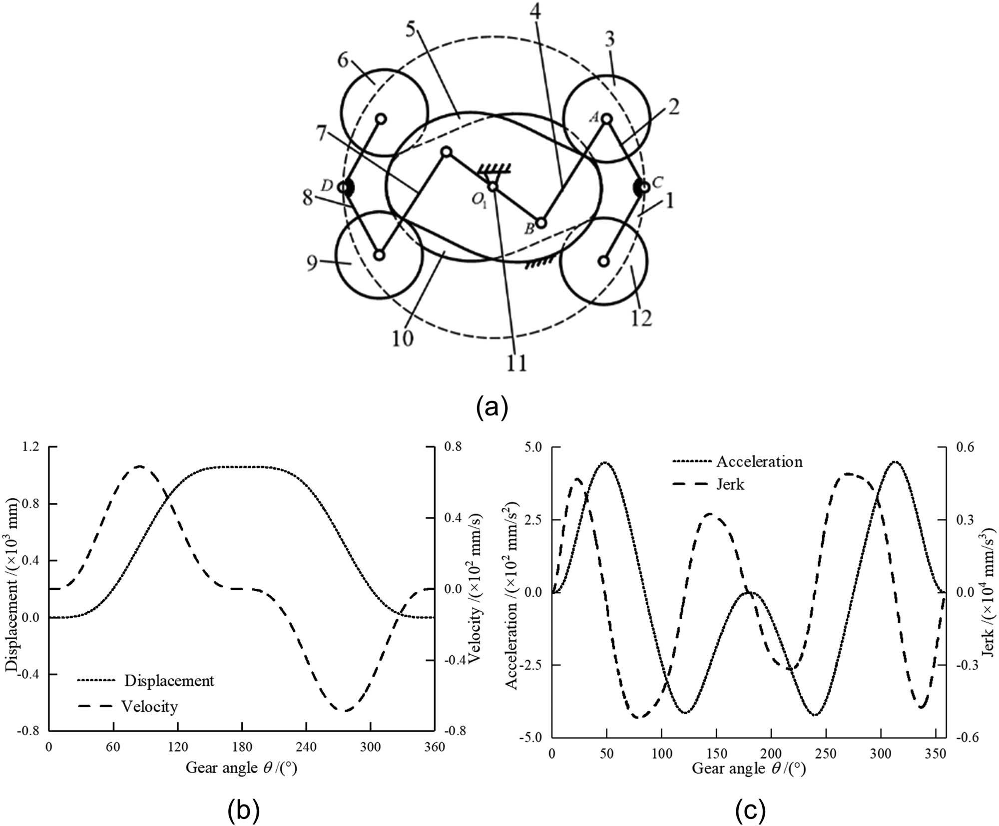
Working principle of the modulator and characteristics of the heald frame. (a) Modulator, (b) displacement and velocity of heald frame, and (c) acceleration and jerk of heald frame.
The cam rollers move along the profiles of the conjugate cams (5 and 10), converting the uniform rotation of the loom into a variable-speed rotational motion of the main shaft through the main shaft connecting rods (4 and 7). It is important to note the relationship between the speed of the dobby motor and the speed of the gear: the input speed of the dobby motor is in a ratio of 2:1 with respect to the gear speed. The motion is then transmitted to the heald frame through the motion transmission mechanism, allowing for the vertical up-and-down movements of the heald frame; the characteristics of the heald frame are illustrated in Figure 1(b) and (c).
The activity of the dobby modulator is conveyed to the heald frame via linkages, with the superiority of its dynamic performance bearing direct ramifications on the loom’s shedding quality. Prevalent scholarly works on the kinematics and dynamics of dobby have yet to account for the consequences of elastic deformation in mechanism components on the heald frame’s motion properties. Nonetheless, as dobby evolve towards lighter designs and higher velocities, the sharp escalation in system inertia and compliance underscores the escalating influence of elastic deformation on systemwide efficacy. The resilience of principal components within the modulator profoundly impacts the dynamic conduct of the entire heald lifting assembly. Accordingly, their vibrational response indispensably influences the dobby system’s dynamic attributes. This research aims to construct a theoretical framework by examining the repercussions of flexible component deformation in a dobby modulator on the heald frame’s shedding capabilities, thus laying a foundation to overcome challenges such as diminished motion stability and compromised reliability. The model delineating the vibrational response of the heald frame is depicted in Figure 2.
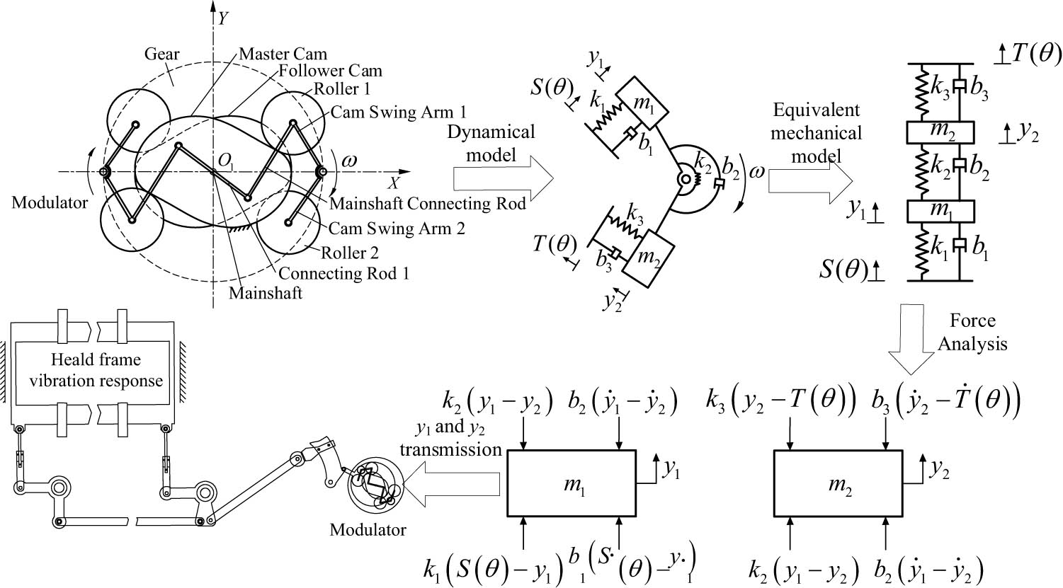
Vibrational response model of the heald frame.
System dynamics examines complex systems that are composed of various mechanisms, leading to the formulation of dynamic equations:
where S(θ) represents the actual displacement of the main cam of the rotary variable speed mechanism; T(θ) denotes the displacement coordinate of the sub cam of the rotary variable speed mechanism; F(θ) is the load acting on the mechanism; y 1 and y 2 are the actual motion displacements of the driven mass blocks m 1 and m 2, respectively; k 1, k 2, and k 3 are the corresponding spring stiffness coefficients; b 1, b 2, and b 3 are the damping coefficients.
Assuming the ideal motion equation for the driven component of the rotary variable speed mechanism, the hypothetical motion equation for the follower component in an ideal modulator is postulated as follows:
where y indicates the displacement of the roller follower in an ideal modulator; U denotes the displacement of the cam actuator in the ideal mechanism; (q 1, q 2, …, q n ) represents the theoretical parameters of each component within the mechanism.
In practical applications of the modulator, one must account for inevitable errors and fluctuations in parameters. It is commonly necessary to adjust the theoretical motion displacement of the active components, specifically the cam’s displacement U, by adding an extra variable amount ΔU, thus obtaining the modified actual motion displacement (U + ΔU). Moreover, the actual parameters of each component are not the static ideal values (q i ), but rather should include the actual variation (Δq i ), and are therefore expressed as (q i + Δq i ). In particular, for the displacement parameter (y 1) of the mass block (m 1), considering such dynamic adjustments, the motion equation must reflect these changes. To accurately describe the dynamic properties, these variable quantities must be integrated into the motion equation, ensuring that it faithfully reproduces the system’s dynamic response under actual operating conditions.
In the functioning of a modulator during actual operation, the cam displacement of the active components is subject to minuscule variations, denoted by (ΔU), due to errors and slight parameter perturbations. Concurrently, a corresponding minute variation, (q i ), may also occur in the parameters of each component. To provide a mathematical description of the system behavior in light of such occurrences, a Taylor series expansion is employed to approximate the changes in cam displacement and component parameters. Given that both (ΔU) and (Δq i ) are diminutive quantities, the expansion process dismisses all terms beyond the first order on the grounds that their contributions are relatively negligible at this scale of measurement. Consequently, the initially complex expressions are reduced to linear expressions incorporating only the first-order variations, (ΔU) and (Δq i ).
The displacement error of the heald frame is defined as:
Assuming that the displacement error of the mechanism’s active components is negligible, that is, when ΔU = 0, equation (5) can be simplified to:
In addressing the issue of displacement errors in the modulator, a Taylor series expansion has been utilized, retaining only the first-order terms to approximate the error function. In this approximation, the partial derivatives ∂y
1/∂U and
In equation (7), S 1(θ) represents the ideal displacement of the heald frame; ΔS(θ) indicates the change in displacement of the heald frame; F 1 represents the initial load of the heald frame; ΔF(θ) indicates the load variation of the heald frame.
To obtain a profound and precise understanding of the static and dynamic behavior of the heald frame, particularly when gears rotate slowly, a range of theoretical assumptions and models have been formulated. A critical assumption among these is the uninterrupted contact between the cam and roller under ideally matched conditions, ensuring that the contact point on the cam surface stays continuous with the roller at all times, avoiding any detachment. The premise of this assumption is the idealization of cam mechanism design to simplify the analysis of actual complex dynamic behaviors.
On this premise, the focus is on the dynamic behavior of the mass block m 1 of the driven component, examining its ability to fulfill the predefined heald frame displacement characteristic curve S 1(θ). This curve delineates the desired displacement trajectory of the driven component as a function of the cam’s rotational angle θ. To further elaborate on this research, Table 1 comprehensively lists the key dynamic parameters of the modulator, encompassing the driven component’s mass, cam’s geometric dimensions, roller’s radius, and the dynamic factors associated with the rotational speed.
Dynamics parameters of the rotary variable speed mechanism
| Parameters | Value | Unit |
|---|---|---|
| m 1 | 6.0 | kg |
| m 2 | 2.5 | N/m |
| K 1 | 2.5 × 10⁷ | N/m |
| K 2 | 3.0 × 10⁸ | N/m |
| K 3 | 2.5 × 10⁷ | Ns/m |
| b 1 | 2.0 | Ns/m |
| b 2 | 3.0 | Ns/m |
| b 3 | 2.0 | N |
| F 0 | 1.0 × 10³ | kg |
2.2 Modulator – heald frame dynamics solution
In order to delve deeper into the vibrational characteristics of the heald frame in operation, this research has adopted nonlinear vibration theory as the basis for analysis and applied the fourth-order Runge–Kutta method for numerical simulations and analytical solutions [14,15,16,17].
The fourth-order Runge–Kutta method is a highly accurate single-step approach widely used in the field of numerical analysis. It offers up to fourth-order precision, meaning that it provides highly accurate solutions at each calculation step, thereby significantly enhancing the accuracy of simulation results. Additionally, the fourth-order Runge–Kutta method excels in numerical stability, effectively handling potential numerical instability issues. This method requires only the first-order derivatives for its calculations, without the need to explicitly define or compute higher-order derivatives, greatly simplifying the computational process. Specifically, given the current step value, the next step value can be directly computed, allowing the method to self-start and avoid complex preprocessing steps. Another important consideration is the relative simplicity of implementing the fourth-order Runge–Kutta method in programming. Consequently, when selecting numerical simulation and calculation methods, we decided to adopt the fourth-order Runge–Kutta method. This choice ensures high accuracy and stability of the simulation results while also simplifying the programming and implementation process, making our research work more efficient and reliable.
In this study, referencing equations (1) through (8), a comprehensive tracking of the mass block m 1’s motion was conducted by amalgamating theory with numerical computations. These equations include the differential equations that depict the dynamic properties of mass block m 1, encompassing its displacement, velocity, and acceleration under the effect of nonlinear forces. Solving these equations enables the plotting of the actual displacement curve y 1 of mass block m 1, which is a critical element in assessing the dynamic characteristics of the heald frame.
During the solution process, the fourth-order Runge–Kutta method employs four distinct approximations to approximate the true solution of the differential equations, taking into account the slope at the current point and the estimated slope in the vicinity of that point. In particular, the method iteratively progresses from the initial conditions to the next time point, calculating four increments in each iteration and combining these increments in a specific weighted average fashion to update the value of the function.
The fourth-order Runge–Kutta method approximates the solution at a given point t n + 1 = t n + h, where h is the step size, by the following steps:
Calculate the slope ( k 1):
(10)Calculate the slope k 2, which is the slope at the midpoint, t n + h/2, y n + h × k 1/2:
(11)Calculate the slope k 3, which is the slope at the midpoint, t n + h/2, y n + h × k 2/2:
(12)Calculate the slope k 4, which is the slope at the point t n + h, y n + h × k 3:
(13)Calculate the next value y n + 1:
This study utilizes the dynamic parameters listed in Table 1 and employs the fourth-order Runge–Kutta method to solve equation (1), thereby obtaining the vibration response of the heald frame.
2.3 Analysis of the dynamics response of the heald frame with different cam profiles
The cam profile exerts a critical influence on the dynamic behavior of the heald frame. In this research, the Monte Carlo method was utilized to perform a comprehensive analysis of the system errors in the cam profile system and their impact on the heald frame’s dynamic response [18,19,20]. To simulate the cam profile errors that might occur in the actual production process with precision, a dedicated model was developed. This model is capable of emulating the shape alterations of the cam profile induced by system errors, as depicted in Figure 3. The objective of this work is to investigate the detailed effects of system errors at various levels (0.01i mm, where i = 1, 2, …, 8) on the vibration response of the heald frame.
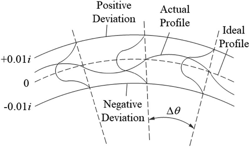
Cam system error model.
In the current investigation, a suite of models was developed to emulate the performance of cam profiles under diverse scopes of random errors (0.01i mm, with i = 1, 2, …, 8), facilitating an examination of the influence of random errors on both the cam profiles and the resultant vibrational response of the heald frame. A model for random errors in the cam is depicted in Figure 4.
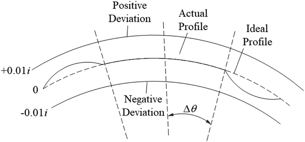
Cam random error model.
3 Analysis and discussion
Program development and algorithms for this study were primarily implemented using the Microsoft Visual Studio 2019 VB.NET platform. In our specific setup, this study configured the appropriate rotational speeds of the dobby to better simulate actual operating conditions. With these configurations, this study was able to compute the results after the dobby operates for 20 work cycles, allowing us to analyze its performance and behavioral characteristics.
Utilizing the cam profile error models presented in Figures 2 and 3, this research investigated the dynamic response of the heald frame over 20 gear cycles post-stabilization, subsequent to the gear completing 1,000 cycles of rotation. The analysis was conducted under the assumption of spring stiffness at k 1 = k 3 = 2.45 × 10⁷ N/m and k 2 = 2.95 × 10⁸ N/m and disregarded any loading effects. The rotational speed of the dobby was incremented from 100 to 1,200 rpm in steps of 100 rpm, as demonstrated in Figure 5. Herein, the vibrational amplitude was characterized as the fluctuation range between the anticipated displacement S(θ) of the heald frame and its actual displacement y 1.
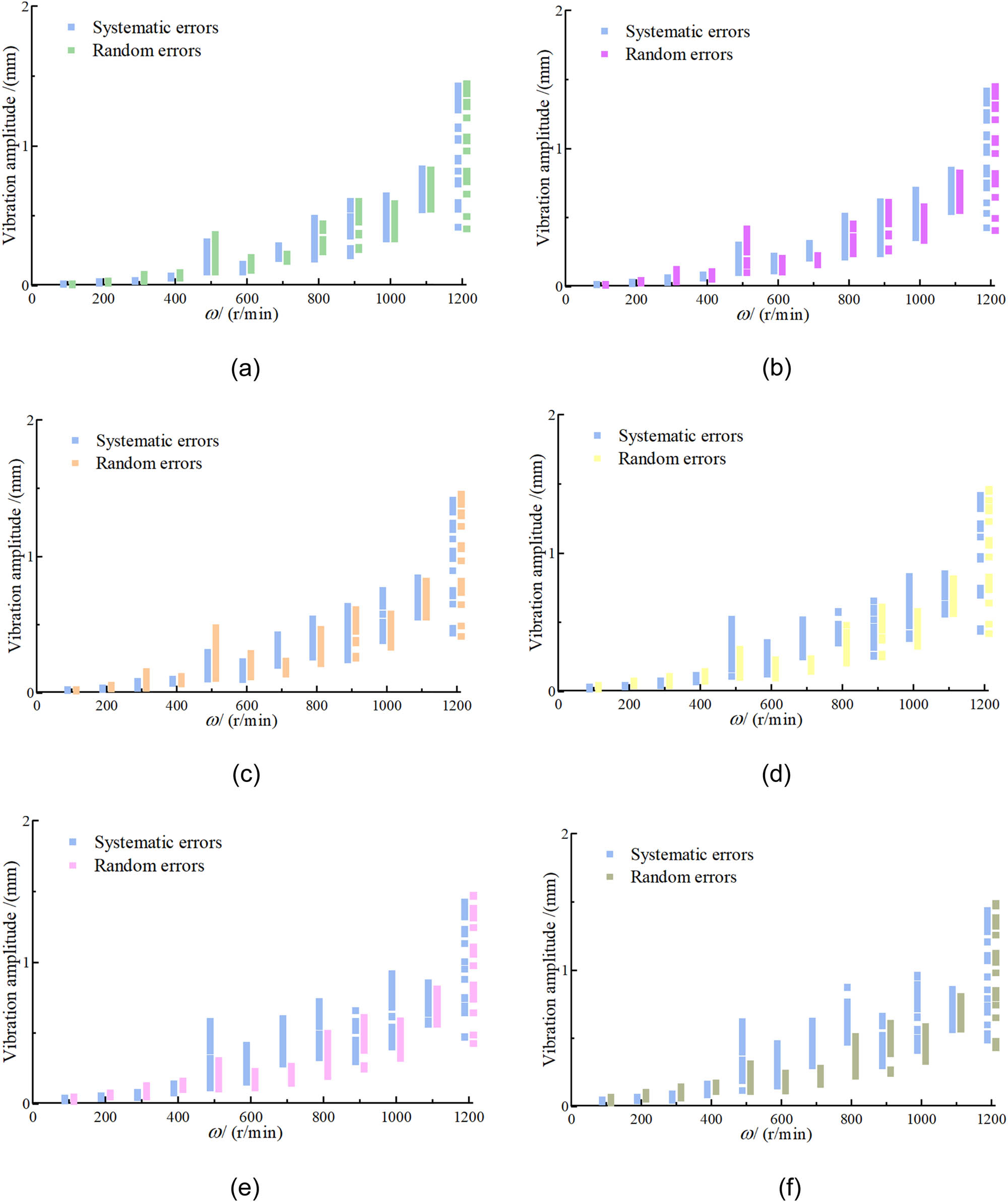
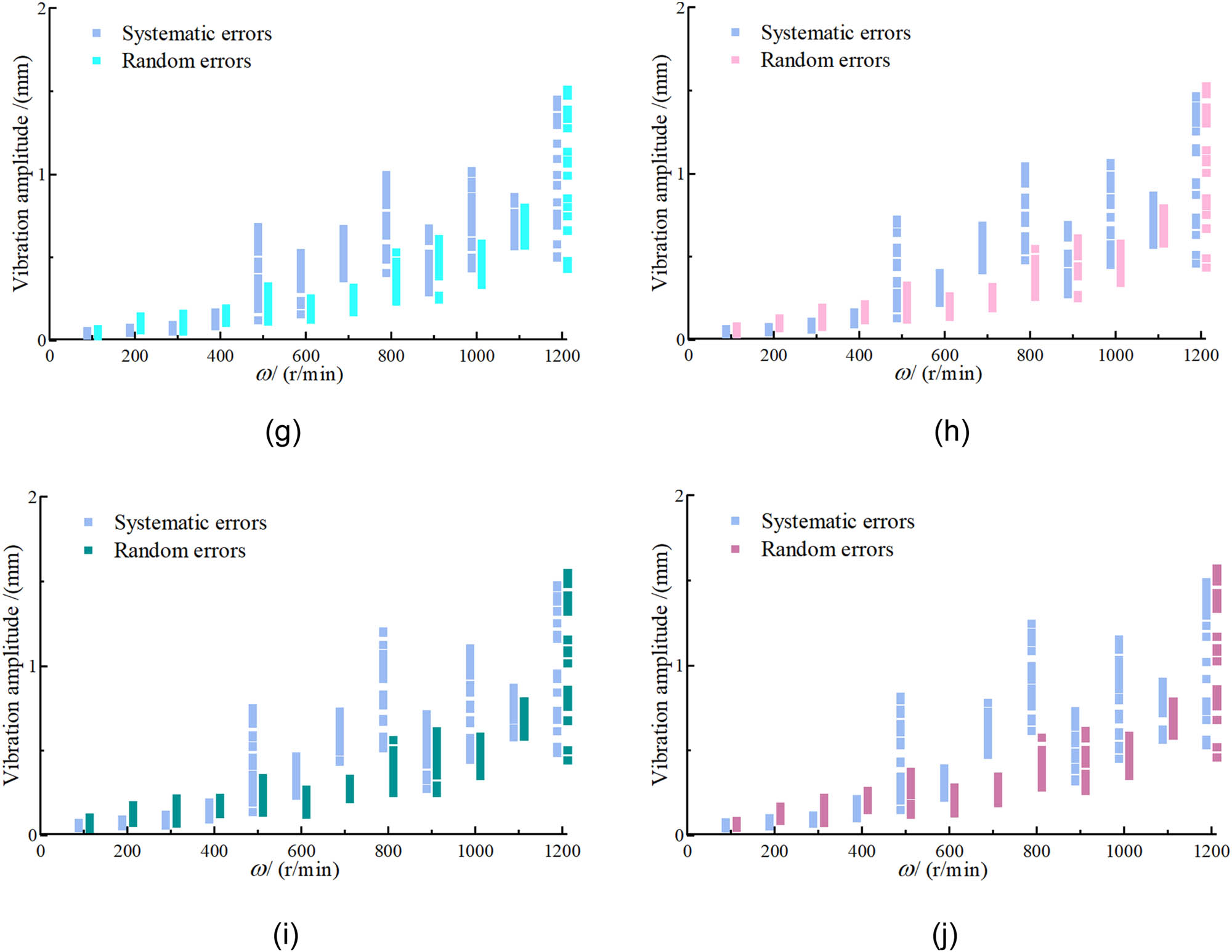
Heald frame vibration response graphs. Cam profile error of (a) 0.01 mm, (b) 0.02 mm, (c) 0.03 mm, (d) 0.04 mm, (e) 0.05 mm, (f) 0.06 mm, (g) 0.07 mm, (h) 0.08 mm, (i) 0.09 mm, and (j) 0.1 mm.
The findings demonstrate that stochastic machining errors in the cam profile have a pronounced impact on the dynamic characteristics of the heald frame, particularly when gear rotational speeds are below 500 rpm. Such influence is predominantly observed in the vibration properties of the heald frame, where the vibration magnitude is considerably affected by the cam profile machining errors at low speeds. Conversely, when the rotational speed of the dobby surpasses 500 rpm, the system errors begin to have a more significant impact on the frame’s vibration magnitude. As the speed continues to increase, especially beyond 800 rpm, the influence of both system and random errors on the vibration magnitude of the heald frame becomes dramatically more pronounced. This suggests that the dynamic performance of the dobby is more sensitive to various errors under high-speed operational conditions. Hence, during the design and operation of dobby, it is crucial to maintain strict control over the operating speeds to prevent them exceeding 800 rpm, in order to mitigate vibration issues that arise from operating at high speeds. The calculated results for vibration amplitudes are presented in detail in Tables 2 and 3, offering quantitative data for support.
Amplitude of vibration response of the heald frame over 20 cycles due to dobby speed variation (systematic error)
| ω/(rpm) | 0.01 mm | 0.02 mm | 0.03 mm | 0.04 mm | 0.05 mm | |||||
|---|---|---|---|---|---|---|---|---|---|---|
| Min | Max | Min | Max | Min | Max | Min | Max | Min | Max | |
| 100 | 0.008 | 0.012 | 0.014 | 0.019 | 0.016 | 0.026 | 0.018 | 0.031 | 0.020 | 0.042 |
| 200 | 0.016 | 0.028 | 0.021 | 0.035 | 0.023 | 0.036 | 0.030 | 0.045 | 0.035 | 0.058 |
| 300 | 0.028 | 0.038 | 0.029 | 0.063 | 0.035 | 0.087 | 0.039 | 0.077 | 0.044 | 0.080 |
| 400 | 0.055 | 0.069 | 0.063 | 0.084 | 0.068 | 0.099 | 0.070 | 0.118 | 0.076 | 0.142 |
| 500 | 0.096 | 0.315 | 0.098 | 0.302 | 0.101 | 0.300 | 0.109 | 0.522 | 0.113 | 0.581 |
| 600 | 0.098 | 0.156 | 0.112 | 0.222 | 0.098 | 0.227 | 0.127 | 0.354 | 0.153 | 0.414 |
| 700 | 0.195 | 0.286 | 0.204 | 0.315 | 0.202 | 0.424 | 0.251 | 0.516 | 0.282 | 0.602 |
| 800 | 0.191 | 0.482 | 0.216 | 0.509 | 0.262 | 0.543 | 0.350 | 0.581 | 0.327 | 0.722 |
| 900 | 0.215 | 0.604 | 0.238 | 0.614 | 0.241 | 0.635 | 0.254 | 0.655 | 0.300 | 0.657 |
| 1,000 | 0.335 | 0.641 | 0.353 | 0.700 | 0.380 | 0.754 | 0.383 | 0.830 | 0.400 | 0.919 |
| 1,100 | 0.542 | 0.837 | 0.542 | 0.841 | 0.552 | 0.845 | 0.557 | 0.849 | 0.560 | 0.854 |
| 1,200 | 0.417 | 1.428 | 0.426 | 1.416 | 0.439 | 1.412 | 0.432 | 1.416 | 0.472 | 1.424 |
| ω/(rpm) | 0.06 mm | 0.07 mm | 0.08 mm | 0.09 mm | 0.1 mm | |||||
|---|---|---|---|---|---|---|---|---|---|---|
| Min | Max | Min | Max | Min | Max | Min | Max | Min | Max | |
| 100 | 0.035 | 0.047 | 0.028 | 0.055 | 0.034 | 0.064 | 0.043 | 0.073 | 0.043 | 0.078 |
| 200 | 0.041 | 0.068 | 0.047 | 0.079 | 0.046 | 0.080 | 0.055 | 0.095 | 0.056 | 0.098 |
| 300 | 0.044 | 0.093 | 0.054 | 0.092 | 0.062 | 0.111 | 0.058 | 0.120 | 0.068 | 0.119 |
| 400 | 0.085 | 0.166 | 0.086 | 0.171 | 0.095 | 0.165 | 0.093 | 0.194 | 0.100 | 0.215 |
| 500 | 0.116 | 0.621 | 0.119 | 0.681 | 0.129 | 0.722 | 0.138 | 0.752 | 0.151 | 0.814 |
| 600 | 0.151 | 0.462 | 0.156 | 0.528 | 0.223 | 0.401 | 0.234 | 0.466 | 0.219 | 0.393 |
| 700 | 0.300 | 0.627 | 0.372 | 0.668 | 0.418 | 0.687 | 0.435 | 0.730 | 0.473 | 0.778 |
| 800 | 0.470 | 0.873 | 0.405 | 0.995 | 0.477 | 1.043 | 0.514 | 1.204 | 0.615 | 1.246 |
| 900 | 0.296 | 0.660 | 0.290 | 0.674 | 0.272 | 0.688 | 0.273 | 0.714 | 0.317 | 0.731 |
| 1,000 | 0.409 | 0.962 | 0.431 | 1.017 | 0.447 | 1.063 | 0.449 | 1.104 | 0.450 | 1.155 |
| 1,100 | 0.562 | 0.859 | 0.566 | 0.864 | 0.572 | 0.868 | 0.577 | 0.870 | 0.560 | 0.904 |
| 1,200 | 0.487 | 1.436 | 0.498 | 1.447 | 0.459 | 1.464 | 0.486 | 1.477 | 0.533 | 1.489 |
Amplitude of vibration response of the heald frame over 20 cycles due to dobby speed variation (random error)
| ω/(rpm) | 0.01 mm | 0.02 mm | 0.03 mm | 0.04 mm | 0.05 mm | |||||
|---|---|---|---|---|---|---|---|---|---|---|
| Min | Max | Min | Max | Min | Min | Max | Min | Max | Min | |
| 100 | 0.007 | 0.013 | 0.012 | 0.019 | 0.014 | 0.027 | 0.018 | 0.045 | 0.017 | 0.050 |
| 200 | 0.018 | 0.035 | 0.025 | 0.044 | 0.030 | 0.056 | 0.038 | 0.077 | 0.051 | 0.075 |
| 300 | 0.029 | 0.081 | 0.035 | 0.123 | 0.033 | 0.158 | 0.038 | 0.107 | 0.049 | 0.131 |
| 400 | 0.051 | 0.092 | 0.053 | 0.109 | 0.064 | 0.120 | 0.073 | 0.146 | 0.102 | 0.162 |
| 500 | 0.097 | 0.368 | 0.101 | 0.418 | 0.248 | 0.105 | 0.103 | 0.307 | 0.304 | 0.304 |
| 600 | 0.107 | 0.198 | 0.105 | 0.204 | 0.119 | 0.291 | 0.097 | 0.231 | 0.115 | 0.231 |
| 700 | 0.172 | 0.225 | 0.157 | 0.224 | 0.138 | 0.234 | 0.147 | 0.238 | 0.145 | 0.265 |
| 800 | 0.242 | 0.441 | 0.239 | 0.454 | 0.214 | 0.466 | 0.206 | 0.481 | 0.195 | 0.498 |
| 900 | 0.260 | 0.604 | 0.257 | 0.607 | 0.254 | 0.608 | 0.250 | 0.609 | 0.245 | 0.610 |
| 1,000 | 0.334 | 0.588 | 0.336 | 0.579 | 0.333 | 0.578 | 0.328 | 0.580 | 0.323 | 0.584 |
| 1,100 | 0.547 | 0.829 | 0.552 | 0.824 | 0.556 | 0.819 | 0.561 | 0.814 | 0.564 | 0.811 |
| 1,200 | 0.406 | 1.444 | 0.408 | 1.449 | 0.414 | 1.454 | 0.420 | 1.459 | 0.426 | 1.469 |
| ω/(rpm) | 0.06 mm | 0.07 mm | 0.08 mm | 0.09 mm | 0.1 mm | |||||
|---|---|---|---|---|---|---|---|---|---|---|
| Min | Max | Min | Max | Min | Min | Max | Min | Max | Min | |
| 100 | 0.025 | 0.071 | 0.027 | 0.070 | 0.033 | 0.082 | 0.036 | 0.106 | 0.048 | 0.085 |
| 200 | 0.054 | 0.104 | 0.063 | 0.147 | 0.068 | 0.127 | 0.074 | 0.178 | 0.087 | 0.168 |
| 300 | 0.059 | 0.145 | 0.056 | 0.163 | 0.075 | 0.192 | 0.071 | 0.219 | 0.073 | 0.219 |
| 400 | 0.111 | 0.173 | 0.105 | 0.191 | 0.119 | 0.213 | 0.127 | 0.221 | 0.149 | 0.259 |
| 500 | 0.107 | 0.313 | 0.112 | 0.324 | 0.124 | 0.325 | 0.133 | 0.338 | 0.120 | 0.372 |
| 600 | 0.116 | 0.245 | 0.126 | 0.253 | 0.136 | 0.261 | 0.124 | 0.270 | 0.128 | 0.283 |
| 700 | 0.162 | 0.281 | 0.168 | 0.318 | 0.189 | 0.318 | 0.212 | 0.333 | 0.189 | 0.347 |
| 800 | 0.221 | 0.515 | 0.234 | 0.530 | 0.259 | 0.545 | 0.248 | 0.560 | 0.280 | 0.575 |
| 900 | 0.240 | 0.609 | 0.247 | 0.608 | 0.249 | 0.611 | 0.252 | 0.615 | 0.261 | 0.616 |
| 1,000 | 0.330 | 0.585 | 0.336 | 0.583 | 0.343 | 0.577 | 0.349 | 0.582 | 0.351 | 0.585 |
| 1,100 | 0.567 | 0.806 | 0.572 | 0.799 | 0.578 | 0.793 | 0.581 | 0.789 | 0.584 | 0.785 |
| 1,200 | 0.430 | 1.486 | 0.431 | 1.506 | 0.432 | 1.526 | 0.444 | 1.549 | 0.459 | 1.568 |
The present study reveals the influence mechanism of cam profile machining errors on the dynamic performance of the heald frame and underscores the significance of accounting for and managing these errors during the design and operation of dobby. By employing precise cam profile machining and rigorous control over operating speeds, it is feasible to mitigate vibration magnitudes significantly, thus bolstering the working stability and weaving efficiency of the dobby. These insights are intimately connected to practical engineering applications, serving not only to corroborate the dependability of the dynamic model formulated but also to offer valuable guidance for the design and enhancement of dobby.
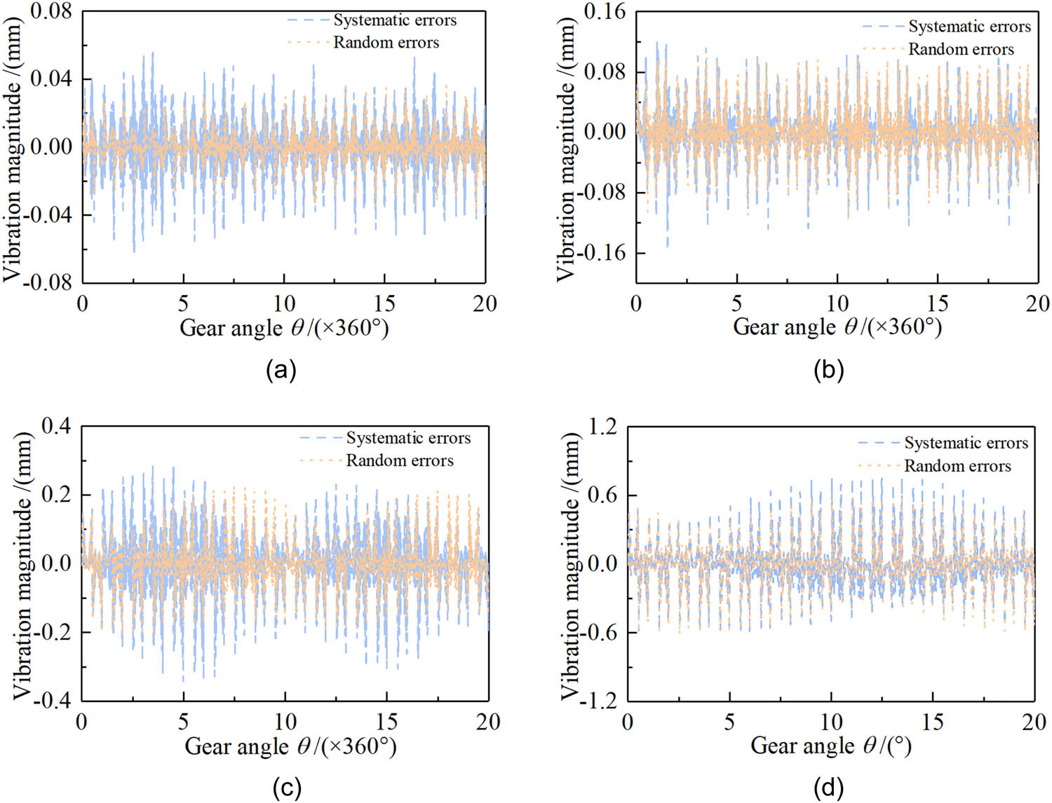
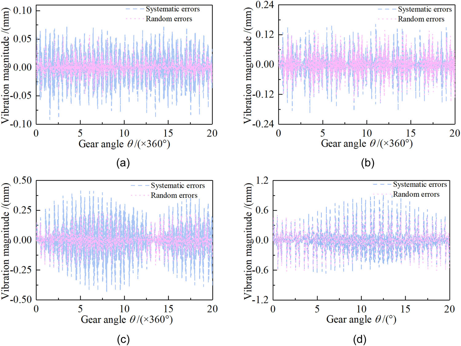
Delving into a more detailed analysis of the resultant findings and conclusions, an examination of the heald frame’s vibrational characteristics over a 20-cycle gear rotation interval was performed. This allowed for a more pronounced observation of the effects that systematic and random cam profile errors have on the dynamic traits of the heald frame. However, due to constraints in length, this article confines its presentation to the vibrational response outcomes of the heald frame at cam profile deviations of 0.01, 0.03, 0.05, 0.07, and 0.1 mm, with the dobby operating at velocities of 100, 400, 600, and 1,000 rpm.
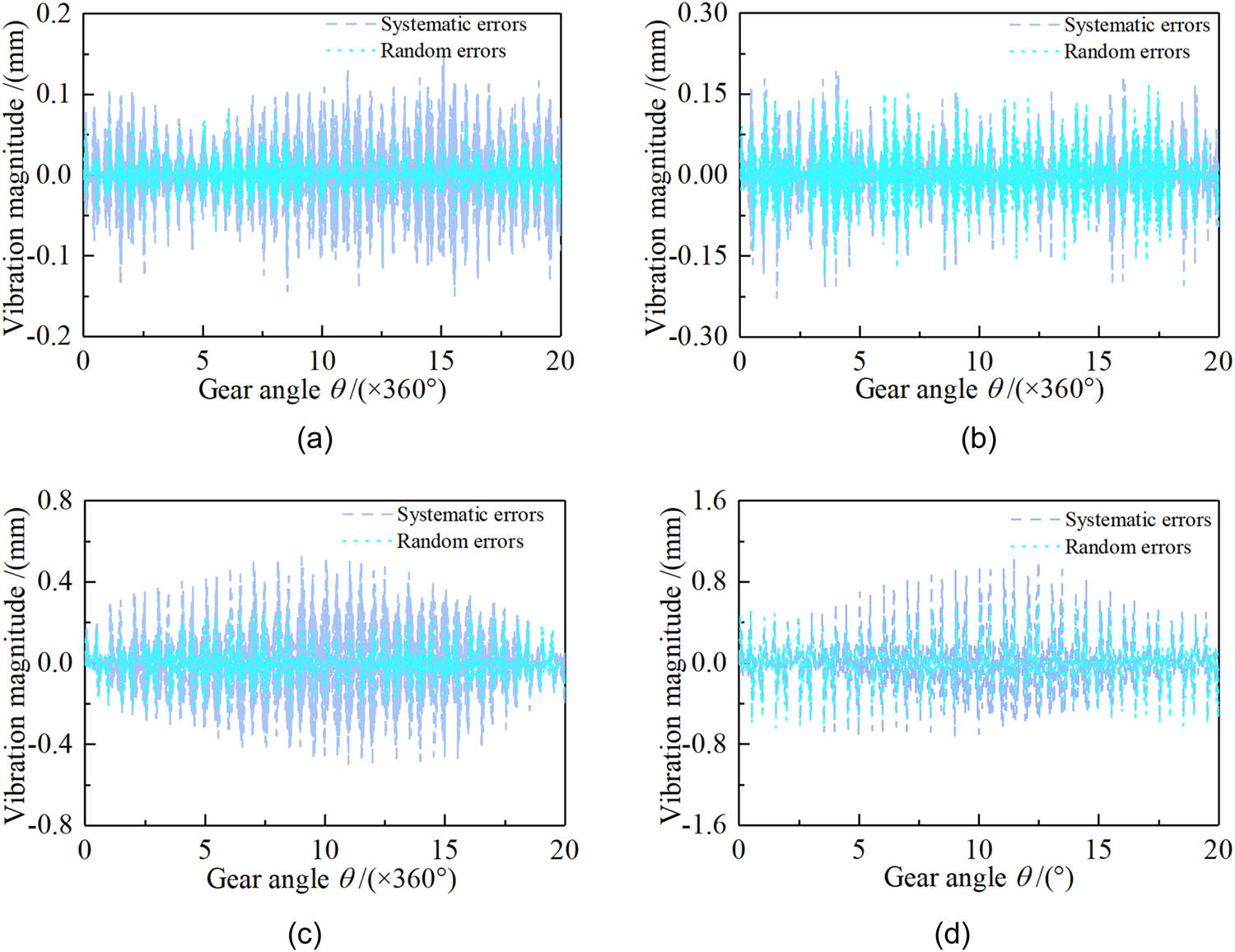
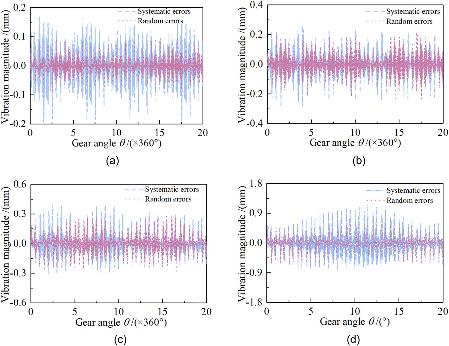
Through an in-depth analysis of Figures 6–10, the profound impact of systematic and stochastic errors in cam profiles on the dynamic behavior of the heald frame is discernible. The illustrated data elucidate how, under various operational speeds of the dobby, both random machining errors and systematic errors impact the vibration characteristics of the heald frame. There is a marked decrease in vibration stability from low to high speeds, with a particularly rapid increase in vibration amplitude once speeds exceed a certain threshold, negatively affecting the regular operation and weaving efficiency. With cam profile errors below 0.03 mm, the heald frame’s vibrations at low-speed operations (not exceeding 500 rpm) are primarily influenced by random machining errors. However, as speed escalates to the middle-to-high speed range (500–800 rpm), systematic errors begin to predominantly influence vibrations. At high speeds (exceeding 800 rpm), the combined effects of systematic and random errors become significant, critically impacting the vibration of the heald frame. When cam profile errors surpass 0.03 mm, at low speeds (not exceeding 300 rpm), vibrations are still mainly attributed to random machining errors, but as speeds range from medium-low to high (300–800 rpm), systematic errors significantly affect vibration amplitudes. Especially when speeds exceed 800 rpm, the interplay of systematic and random errors causes a sharp increase in the vibration amplitude, severely affecting the dynamic response and operational stability of the dobby. The repercussions extend beyond increased vibration intensity, accelerating wear on moving components and decreasing the overall performance and lifespan of the machinery. Thus, it is critical to maintain precision in cam profile manufacturing and ensure operation at safe speeds for the dobby. To enhance the vibration stability and reliability of the heald frame, meticulous control of the cam profile machining process is required to minimize both systematic and random errors. This might involve refining the cam design, employing more precise machining tools, and enacting more rigorous quality control protocols. Additionally, regular maintenance and calibration of the dobby are imperative for long-term stable operations.
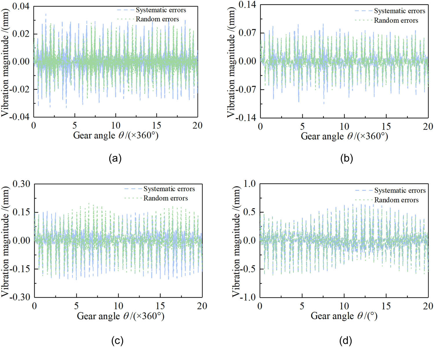
Heald frame vibration magnitude – cam profile error of 0.01 mm. Dobby rotational speed: (a) 100 rpm, (b) 400 rpm, (c) 600 rpm, and (d) 1,000 rpm.
Heald frame vibration magnitude – cam profile error of 0.03 mm. Dobby rotational speed: (a) 100 rpm, (b) 400 rpm, (c) 600 rpm, and (d) 1,000 rpm.
Heald frame vibration magnitude – cam profile error of 0.05 mm. Dobby rotational speed: (a) 100 rpm, (b) 400 rpm, (c) 600 rpm, and (d) 1,000 rpm.
Heald frame vibration magnitude – cam profile error of 0.07 mm. Dobby rotational speed: (a) 100 rpm, (b) 400 rpm, (c) 600 rpm, and (d) 1,000 rpm.
Heald frame vibration magnitude – cam profile error of 0.1 mm. Dobby rotational speed: (a) 100 rpm, (b) 400 rpm, (c) 600 rpm, and (d) 1,000 rpm.
Consequently, the consequences of cam profile machining errors on the dynamic characteristics of the heald frame are significant, impacting the overall performance and economic viability of the dobby. By implementing proper design, machining, and operational strategies, the vibration stability of the heald frame can be notably improved, thus ensuring efficient, stable, and long-term operation of the dobby.
4 Conclusions
This research delves into the dynamics of dobby, specifically addressing the effects of the modulator on the dynamic reactions of the heald frame. A detailed mathematical framework has been developed, and with the application of the fourth-order Runge–Kutta numerical simulation technique, the dynamic behavior of the heald frame under varying operating conditions can be precisely analyzed and forecasted. The study underscores the necessity of incorporating the elasticity of components in both the design and functioning of dobby due to its substantial influence on system performance. By constructing a vibration model for the heald frame, the pivotal role of elastic deformation in sustaining opening performance is demonstrated, a role that grows in importance relative to the machine’s operational velocity. Furthermore, the findings reveal that cam profile deviations, encompassing both random machining and systematic inaccuracies, profoundly affect the vibration properties of the heald frame. These discrepancies are especially critical at elevated speeds where they amplify vibration magnitudes and potentially propel the system beyond its critical threshold, jeopardizing the machinery’s overall stability.
The study’s crucial contribution lies in its proposed methodology to enhance the dobby performance via dynamic scrutiny and refined design. Precise cam profile machining, design improvements, and the implementation of suitable operational protocols can collectively reduce vibration issues of the heald frame. Additionally, consistent maintenance and calibration are key to the machine’s enduring stability. Overall, this research not only broadens the comprehension of dobby dynamics but also offers actionable guidance to boost their stability, dependability, and operational lifespan. Prospective endeavors could further integrate enhanced predictive models in early design stages to mitigate or circumvent dynamic complications, facilitating the dobby’s high-efficiency and steadfast performance.
When a rotary dobby with this cam-link modulator is applied to different looms or different fabrics, especially at different speeds, further analysis of the characteristics of the dynamics of the heald frame is required.
Acknowledgements
The authors disclosed receipt of the following financial support for the research, authorship, and/or publication of this article: This research was financially funded by the Tianjin Science and Technology Plan Project (No. 23YDTPJC00390) and the Tianjin Municipal Education Commission Scientific Research Plan Project (grant number 2022ZD002).
-
Funding information: This research was financially funded by the Tianjin Science and Technology Plan Project (No. 23YDTPJC00390) and the Tianjin Municipal Education Commission Scientific Research Plan Project (grant number 2022ZD002).
-
Author contributions: Honghuan Yin: Conceptualization, Methodology, Writing – Original Draft. Hongbin Yu: Data Curation, Formal Analysis, Visualization, Supervision, Project Administration. Weiye Zhang: Investigation, Resources, Validation, Writing – Review & Editing.
-
Conflict of interest: The authors state no conflict of interest.
-
Ethical approval: The conducted research is not related to either human or animal use.
-
Data availability statement: The datasets generated during and/or analyzed during the current study are available from the corresponding author on reasonable request.
References
[1] Umair M, Nawab Y, Malik MH, Shaker K. Development and characterization of three-dimensional woven-shaped preforms and their associated composites. J Reinf Plast Compos. 2015;34(24):2018–28.Suche in Google Scholar
[2] Wang HW, Tao ZQ, Fu YL, Bai H, Xiao HQ. High speed dynamic characteristics research for LL680 flexible rapier loom. Adv Mater Res. 2014;850–851:274–8.Suche in Google Scholar
[3] Abdullayev G, Palamutcu S, Hasçelik B, Soydan A. Synthesis of a new dobby mechanism. Tekstil. 2006;55:184–8.Suche in Google Scholar
[4] Bílek M, Skřivánek J. Mathematical modeling of the system shedding motion-heald-warp. Autex Res J. 2013;14:42–6.Suche in Google Scholar
[5] Yin HH, Yu HB, Wang L. Kinematic comparison of a heald frame driven by a rotary dobby with a cam-slider, a cam-link and a null modulator. Autex Res J. 2021;21(3):323–32.Suche in Google Scholar
[6] Abdulla G, Hasçelik B, Palamutcu S, Soydan A. Synthesis work about driving mechanism of a novel rotary dobby mechanism. Tekst Konfeksiyon. 2010;20(03):218–24.Suche in Google Scholar
[7] Abdulla G, Can O. Design of a new rotary dobby mechanism. Ind Text. 2018;69(06):429–33.Suche in Google Scholar
[8] Farid M, Cleghorn WL. Dynamic modeling of multi flexible link planar manipulators using curvature based finite element method. J Vib Control. 2014;20(11):1682–96.Suche in Google Scholar
[9] Lei JT, Yu HY, Wang TM. Dynamic bending of bionic flexible body driven by Pneumatic Artificial Muscles (PAMs) for spinning gait of quadruped robot. Chin J Mech Eng. 2016;29(01):11–20.Suche in Google Scholar
[10] Yu H, Yin H, Peng J, Wang L. Quasi static analysis of heald frame driven by rotary dobby with cam-linkage modulator. J Text Eng. 2020;66(03):37–45.Suche in Google Scholar
[11] Gokarneshan N, Jegadeesan N, Dhanapal P. Recent innovations in loom shedding mechanisms. Indian J Fibre Text Res. 2010;35(01):85–94.Suche in Google Scholar
[12] Bhattacharya SK, Das K. Suitability of cycloidal cam in shedding mechanism. Indian J Fiber Text Res. 2006;31(03):465–6.Suche in Google Scholar
[13] Eren R, Alpay HR. Analytical design method for cam shedding motions in weaving. Indian J Fibre Text Res. 2005;30(02):125–35.Suche in Google Scholar
[14] Yin H, Yu H, Peng J, Shao H. Mathematical model of cam profile based on heald frame motion characteristics. Math Probl Eng. 2020;2020:1–9.Suche in Google Scholar
[15] Sadettin K, Taylan DM, Ali K. Cam motion tuning of shedding mechanism for vibration reduction of heald frame. Gazi Univ J Sci. 2010;23(02):227–32.Suche in Google Scholar
[16] Korolev PA, Lohmanov VN. Kinematics of connections of the shedding mechanism of a circular loom TKP-110-U. Lzv Vyssh Uchebn Zavede Seriya Teknologiya. 2011;4:116–9.Suche in Google Scholar
[17] Mueller A. Screw and Lie group theory in multibody dynamics recursive algorithms and equations of motion of tree-topology systems. Multibody Syst Dyn. 2018;42(02):219–48.Suche in Google Scholar
[18] Yu H, Yin H, Peng J, Wang L. Comparison of the vibration response of a rotary dobby with cam-link and cam-slider modulators. Autex Res J. 2021;21(4):491–500.Suche in Google Scholar
[19] Hurtado JE. Analytical dynamics of variable-mass systems. J Guid Control Dyn. 2018;41(03):701–9.Suche in Google Scholar
[20] Yin H, Xiao Z, Yu H, Shao H, Reconstructing method for cam profile of dobby modulator using the particle swarm opti-mization. Proc Inst Mech Eng, Part C, 2020, 235(20): 4977-87.Suche in Google Scholar
© 2024 the author(s), published by De Gruyter
This work is licensed under the Creative Commons Attribution 4.0 International License.
Artikel in diesem Heft
- Characterization of viscoelastic properties of yarn materials: Dynamic mechanical analysis in the transversal direction
- Analysis of omni-channel implementations that are preferred by consumers in clothing sector
- Structural modeling and analysis of three-dimensional cross-linked braided preforms
- An experimental study of mechanical properties and comfortability of knitted imitation woven shirt fabrics
- Technology integration to promote circular economy transformation of the garment industry: a systematic literature review
- Research on T-shirt-style design based on Kansei image using back-propagation neural networks
- Research on She nationality clothing recognition based on color feature fusion with PSO-SVM
- Accuracy prediction of wearable flexible smart gloves
- Preparation and performance of stainless steel fiber/Lyocell fiber-blended weft-knitted fabric
- Development of an emotional response model for hospital gown design using structural equation modeling
- Preparation and properties of stainless steel filament/pure cotton woven fabric
- Facemask comfort enhancement with graphene oxide from recovered carbon waste tyres
- Use of enzymatic processes in the tanning of leather materials
- Optical-related properties and characterization of some textile fibers using near-infrared spectroscopy
- Network modeling of aesthetic effect for Chinese Yue Opera costume simulation images
- Predicting consumers’ garment fit satisfactions by using machine learning
- Non-destructive identification of wool and cashmere fibers based on improved LDA using NIR spectroscopy
- Study on the relationship between structure and moisturizing performance of seamless knitted fabrics of protein fibers for autumn and winter
- Antibacterial and yellowing performances of sports underwear fabric with polyamide/silver ion polyurethane filaments
- Numerical and experimental analysis of ballistic performance in hybrid soft armours composed of para-aramid triaxial and biaxial woven fabrics
- Phonetic smart clothing design based on gender awareness education for preschoolers
- Determination of anthropometric measurements and their application in the development of clothing sizing systems for women in the regions of the Republic of Croatia
- Research on optimal design of pleated cheongsam based on Kano–HOQ–Pugh model
- Numerical investigation of weaving machine heald shaft new design using composite material to improve its performance
- Corrigendum to “Use of enzymatic processes in the tanning of leather materials”
- Shaping of thermal protective properties of basalt fabric-based composites by direct surface modification using magnetron sputtering technique
- Numerical modeling of the heat flow component of the composite developed on the basis of basalt fabric
- Weft insertion guideway design based on high-temperature superconducting levitation
- Ultrasonic-assisted alkali hydrolysis of polyethylene terephthalate fabric and its effect on the microstructure and dyeing properties of fibers
- Comparative study on physical properties of bio-based PA56 fibers and wearability of their fabrics
- Investigation of the bias tape roll change time efficiency in garment factories
- Analysis of foot 3D scans of boys from Polish population
- Optimization of garment sewing operation standard minute value prediction using an IPSO-BP neural network
- Influence of repeated switching of current through contacts made of electroconductive fabrics on their resistance
- Numerical calculation of air permeability of warp-knitted jacquard spacer shoe-upper materials based on CFD
- Compact Spinning with Different Fibre Types: An Experimental Investigation on Yarn Properties in the Condensing Zone with 3D-Printed Guiding Device
- Modeling of virtual clothing and its contact with the human body
- Advances in personalized modelling and virtual display of ethnic clothing for intelligent customization
- Investigation of weave influence on flame retardancy of jute fabrics
- Balloonless spinning spindle head shape optimisation
- Research on 3D simulation design and dynamic virtual display of clothing flexible body
- Turkish textile and clothing SMEs: Importance of organizational learning, digitalization, and internationalization
- Corrigendum To: “Washing characterization of compression socks”
- Study on the promotion multiple of blood flow velocity on human epidermal microcirculation of volcanic rock polymer fiber seamless knitted fabric
- Bending properties and numerical analysis of nonorthogonal woven composites
- Bringing the queen mother of the west to life: Digital reconstruction and analysis of Taoist Celestial Beings Worshiping mural’s apparel
- Modeling process for full forming sports underwear
- Retraction of: Ionic crosslinking of cotton
- An observational study of female body shape characteristics in multiracial Malaysia
- Study on theoretical model and actual deformation of weft-knitted transfer loop based on particle constraint
- Design and 3D simulation of weft-knitted jacquard plush fabrics
- An overview of technological challenges in implementing the digital product passport in the textile and clothing industry
- Understanding and addressing the water footprint in the textile sector: A review
- Determinants of location changes in the clothing industry in Poland
- Influence of cam profile errors in a modulator on the dynamic response of the heald frame
- Quantitative analysis of wool and cashmere fiber mixtures using NIR spectroscopy
- 3D simulation of double-needle bar warp-knitted clustered pile fabrics on DFS
- Finite element analysis of heat transfer behavior in glass fiber/metal composite materials under constant heat load
- Price estimation and visual evaluation of actual white fabrics used for dress shirts and their photographic images
- Effect of gluing garment materials with adhesive inserts on their multidirectional drape and bending rigidity
- Optimization analysis of carrier-track collision in braiding process
- Numerical and experimental analysis of the ballistic performance of soft bulletproof vests for women
- The antimicrobial potential of plant-based natural dyes for textile dyeing: A systematic review using prisma
- Influence of sewing parameters on the skin–fabric friction
- Validation by experimental study the relationship between fabric tensile strength and weave structures
- Optimization of fabric’s tensile strength and bagging deformation using surface response and finite element in stenter machine
- Analysis of lean manufacturing waste in the process flow of ready-to-wear garment production in Nigeria
- An optimization study on the sol–gel process to obtain multifunctional denim fabrics
- Drape test of fully formed knitted flared skirts based on 3D-printed human body posture
- Supplier selection models using fuzzy hybrid methods in the clothing textile industry