Design and 3D simulation of weft-knitted jacquard plush fabrics
-
Xiuping Mu
 ,
Gaoming Jiang
,
Songsong Guan
,
Gaoming Jiang
,
Songsong Guan

Abstract
Weft-knitted jacquard plush fabrics are widely used and have a wide variety of varieties, but the design and production process is complicated, time-consuming, and labor-intensive. To reduce the time and cost of fabric sampling and production, a method for designing and simulating these fabrics is proposed based on an analysis of their structural characteristics. Following the design principles of weft-knitted jacquard plush fabrics, mathematical models for pattern design and structural design were established sequentially, leading to the generation of a mathematical model for the knitting diagram. Arrays for raw material editing and threading editing were created to set various parameters. Second, loop models were established based on plush loop shapes, including a forming loop model, a U-shaped loop model, a Henkel plush loop model, a “8”-shaped plush loop model, and a O-shaped plush loop model. Finally, the effects of lighting and number of segments were investigated in THREE.Tube Geometry on the simulation’s effectiveness and speed. By comparing actual fabric images with simulation images, the feasibility of the design and simulation method was verified. This resulted in a computer-aided design process for weft-knitted jacquard plush fabrics, providing an effective method for their design and simulation. The proposed method holds significant theoretical and practical values.
1 Introduction
Weft-knitted jacquard plush fabrics are a type of weft-knitted plush fabric characterized by patterns and a three-dimensional effect achieved through needle selection or sinker selection [1]. Due to their soft and skin-friendly properties, these fabrics have long been used for women’s casual outerwear, baby clothes, and towels. In recent years, with the rise of plush fabrics, weft-knitted jacquard plush fabrics have become popular in winter clothing due to their rich colors, ingredient warmth, and low shedding after shearing. They are also widely used in car seats, sofas, and curtains, enjoying great popularity among consumers and experiencing increasing market demand [2,3].
To meet the needs of developers for efficient and convenient design of weft-knitted jacquard plush fabrics, computer-aided design (CAD) of these fabrics has become a major trend [4]. The research and development of CAD systems for weft-knitted jacquard plush fabrics mainly focus on pattern design and 3D simulation, providing convenient methods for design and saving sampling time and costs [5,6].
Currently, there is extensive research on weft-knitted design and simulation systems. Many scholars have established mathematical matrix models, common loop geometric models, and loop-type value point models to achieve 3D simulation of various types of fabrics [7,8]. Zheng et al. [9], Chen et al. [10], and Shen et al. [11] have all realized the design and 3D simulation of different types of weft-knitted fabrics by constructing loop-type particle models. In addition to loop model construction, Zhang et al. [12] used texture slicing to achieve 3D simulation of velvet fabrics. Based on the completion of design and geometric model establishment, Zheng and Jiang [13] and Liu et al. [14] established and analyzed the impact of lighting models, segment counts, and face counts on fabric 3D simulation effects.
Most studies on the 3D design and simulation of plush fabrics focus on woven and warp-knitted plush fabrics. For instance, Wang et al. [15] proposed a simulation method for warp-knitted plush fabrics – loop model filling method – based on loop modeling data analysis and loop morphology influence factor analysis, achieving 3D simulation of warp-knitted towel fabrics under ideal conditions. Cong et al. [16] studied the establishment methods of large design and 3D geometric models for warp-knitted jacquard towel fabrics and achieved the design and 3D simulation of warp-knitted jacquard plush fabrics using the OpenGL graphics library. Han et al. [17,18] analyzed the morphological characteristics of individual loops and achieved 3D simulation of high-pile tufted carpets using point light sources and parallel light sources in the Direct3D environment. Dai et al. [19] constructed 3D models of plush loops using non uniform rational B-Splines (NURBS) curves in 3DMax and simulated loop extrusion deformation in the microsoft visual C++ environment using Direct3D. However, there is limited research on the 3D simulation of weft-knitted plush fabrics [7]. Notably, Guo and Jiang [1] used 2D matrices to convert fabric patterns and knitting diagrams into mathematical models and developed a CAD system for designing weft-knitted jacquard plush fabrics, but did not address 3D simulation.
To achieve the design and 3D simulation of weft-knitted jacquard plush fabrics, this study adopts a mathematical modeling approach. First, mathematical models for pattern design, structural design, and knitting diagrams were established. Then, the design of weft-knitted plush fabrics was realized by combining raw material editing and threading editing arrays. Subsequently, basic loop models and various plush loop models were established, and segment counts, face counts, and lighting systems were set up. Finally, 3D simulation of weft-knitted jacquard plush fabrics was achieved on the VS2022 platform using C# and JavaScript programming languages.
2 Knitting characteristics
The plush structure refers to the fancy structure composed of elongated plush sinker loops and formed loops [20]. Circular weft-knitted jacquard plush fabric refers to a product in which plush loops form a pattern design and color effect on the fabric surface. Based on different knitting methods, they can be divided into sinker-selected jacquard plush fabrics and needle-selected jacquard plush fabrics.
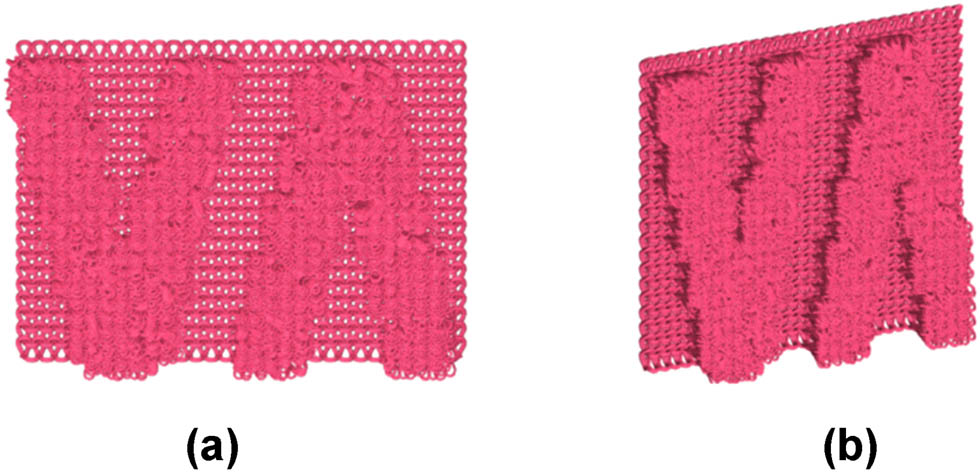
The plush structure can be knitted using multi-feeder plush circular knitting machines. By changing the cams of 2–4 feeders and feeding yarns of different colors, jacquard effects can be created. Alternatively, electronic jacquard plush circular knitting machines can be used, which mainly include two knitting methods: electronic needle selection and sinker selection. Needle selection jacquard plush machines generally use double sinkers and pre-bending yarn technology. This method can use up to 12 different colored yarns to knit full-pattern jacquard plush fabrics. However, long floats are often formed during knitting, so the fabric typically undergoes shearing to produce velour fabrics with color effects, as shown in Figure 1(a). Sinker selection jacquard weft-knitted plush machines can create a relief effect by controlling the advancement or depth of advancement of specially designed sinkers. These sinkers have different nose heights at various parts, resulting in different plush loop heights [20]. Some machines use sinkers of different heights and special selection devices to form plush loops of varying heights [21]. They can knit 1–3 heights of jacquard plush, including high plush area A, low plush area B, and no plush area C, as shown in Figure 1(b). The no plush areas are filled with plating, and the combination of no plush, low plush, and high plush forms an embossed jacquard plush with a relief effect. Sinker selection can also be used to knit jacquard plush fabrics with color effects. This mainly utilizes high sinkers to create longer sinker loops, providing better plush coverage. By controlling the sinkers to form interlaced structures of plating and plush loops, different colored yarns are used to produce sinker-selected knitted jacquard plush fabrics.
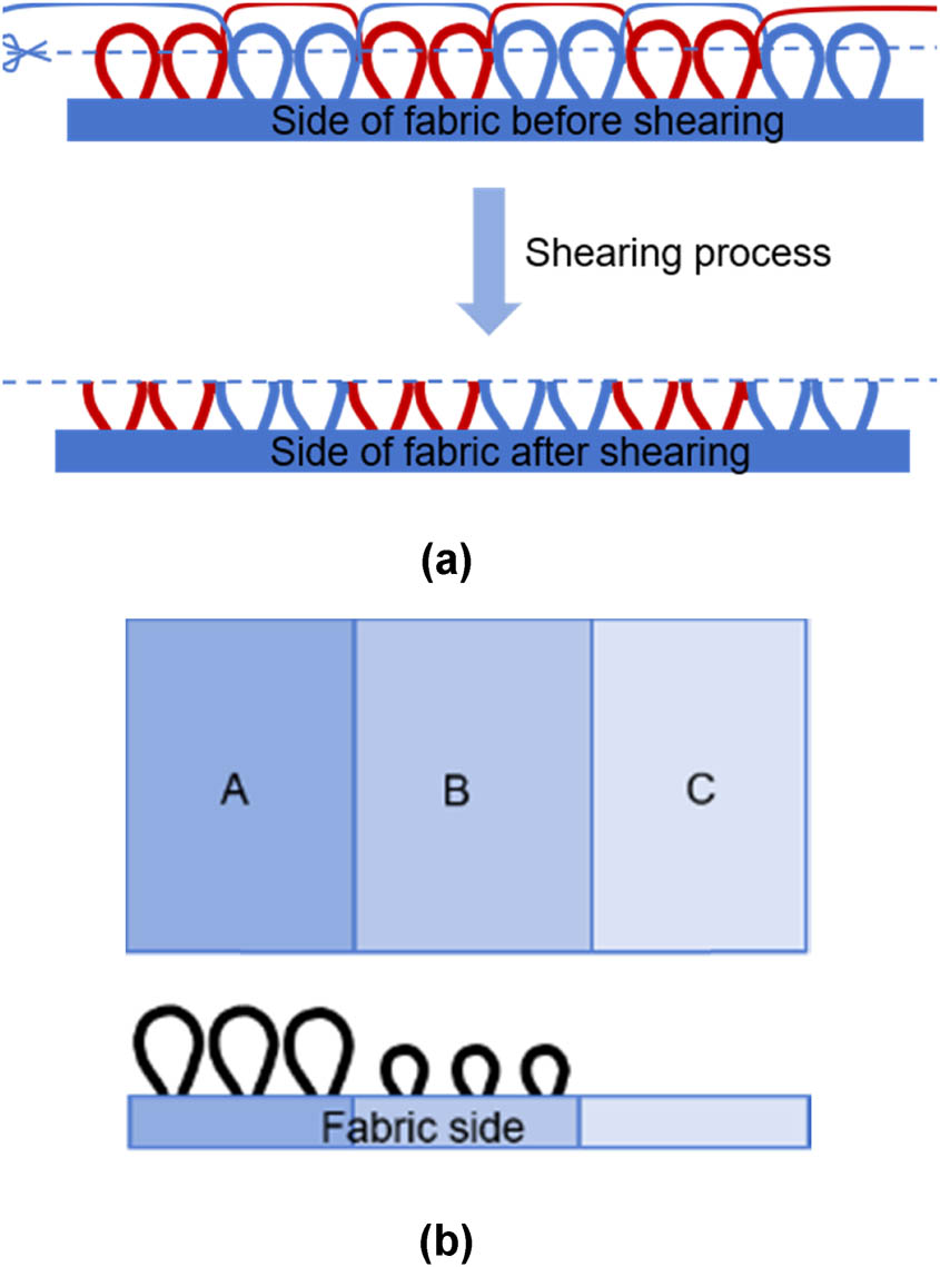
Schematic diagram of different types of (a) the formation process of needle selection jacquard plush loops and (b) 3-height of Henkel loop.
3 Mathematical modeling
3.1 Pattern design diagram model
The pattern design diagram of weft-knitted jacquard plush fabrics uses a two-dimensional (2D) graphic format to briefly reflect the fabric pattern design. By combining knitting information such as the presence or absence of plush loops, loop heights, and pattern designs, the knitting data in the pattern repeat are converted into a 2D matrix, thereby achieving the digitization of the pattern repeat design diagram.
Generally, the minimum repeating unit of a weft-knitted fabric pattern is called the pattern repeat. The pattern diagram of weft-knitted jacquard plush fabrics can be represented by its smallest pattern repeat, with its size denoted in pixel (px) units, where one pixel corresponds to one pattern design grid. The height of a pattern in a pattern cycle is represented by the number of vertical courses on the pattern design diagram, denoted by h, while the width of a pattern in a pattern cycle is represented by the number of horizontal wales w on the pattern design diagram. The height of the pattern in the pattern design diagram ultimately determines the height and width of the simulation.
In the design of pattern diagrams for weft-knitted jacquard plush fabrics, different design colors are used to distinguish the knitting information of different areas. Convert the fabric into a two-dimensional matrix M = (m i,j ) h,w based on the color code of the pattern design; establish a mathematical model for the pattern design, where i represents the number of horizontal wales in the loop; j represents the number of vertical course in the loop; m i,j represents the pattern design information in the ith horizontal wale and jth vertical course; assign a color code, i.e., the design color k in equation (1); and establish a mathematical model for the pattern design diagram, where k = 101,102… t, corresponding one-to-one with the design color code, t takes the maximum value of k:
Different pattern design diagrams can be represented by matrices corresponding to numerical values, and Figure 2 shows the specific correspondence between the two.

Pattern design diagram and corresponding matrix.
3.2 Structure design diagram model
The knitting diagram of the fabric corresponds to the entire piece of fabric and can be further decomposed into a structure diagram model for design purposes. According to the different areas represented by each design color code, the knitting actions of their minimum repeats are drawn separately as regional structure diagrams N k . The main knitting actions of the plush structure are represented by different knitting action color codes: Color code 1 represents the ground yarn loop knitting, Color code 9 represents the float, Color code 23 represents the plating, Color code 28 represents the Henkel plush, Color code 35 represents the “O”-shaped plush, Color code 39 represents the “8”-shaped plush, and Color code 40 represents the “U”-shaped plush. The correspondence between knitting action codes and icons is shown in Table 1.
Knitting action codes and icons
| Loop code | Icon | Meaning |
|---|---|---|
| 1 |
 |
Looping |
| 9 |
 |
Floating |
| 23 |
 |
Plating |
| 28 |
 |
Henkel plush |
| 35 |
 |
“O”-shaped plush |
| 39 |
 |
“8”-shaped plush |
| 40 |
 |
“U”-shaped plush |
Since the knitting diagram is knitted from bottom to top, the structure diagram matrix and the knitting diagram matrix in this article are both in reverse order, defined as a 2D matrix N k = (n i,j ) h2,w2, where h2 is the height of the regional structure graph, w2 is the width of the regional structure graph, and n i,j represents the knitting action at the ith course and jth wale of the regional structure graph.
The regional structure graphs are combined to form the structure design graph N of the fabric as shown in Equation (2), constructing a two-dimensional matrix N = (n i,j ) h3,w3, where t = 100 represents the number of regional structure graphs; h3 = h2 represents the height of the structure design graph; w3 represents the width of the structure design graph, which is the total width of all regional structure graphs; and n i,j represents the knitting action at the ith course and jth wale in the structure design graph:
Each course of the structure design graph corresponds to a function area F on the right, as shown in Equation (3), with a width of 3 and height h. Represent the threading order of the fabric as F1; the number of courses in the pattern design diagram corresponds to each yarn, i.e., the threading routes as F2; and the yarn threading information F3. Here, color code 1 represents one type of material, color code 2 represents another, and so on.
The basic yarn threading information can be automatically generated through the information set in the functional area of the structure design diagram and the expanded knitting design diagram, including parameters such as process rows, pattern rows, knitting status, plush height, the number of segments and faces, and the random deflection angle range of the plush loops. Here are the details:
The number of process rows is equal to the height of the knitting diagram calculated in Section 3.3.
The height of the pattern rows corresponds to the height of the pattern design diagram.
The knitting status is related to whether each process row contains a plush color code. If it contains a plush color code, the knitting status is set to “plush”.
The plush height is related to the corresponding plush color code. Different plush heights correspond to different default values.
The number of segments and faces is assigned according to the optimal values tested in Section 5.1.
The deflection angle of the plush loops is assigned different default values according to the corresponding plush height:
Figure 3 shows the structure design diagram of the plush fabric and its corresponding structure design graph matrix. This fabric uses two regional structure graphs, N101 and N102, corresponding to the color regions 101 and 102 of the pattern design graphics. The function bar sets the fabric with two yarns representing one course, which also constitutes one course in the pattern design diagram (including plush yarn and base yarn).
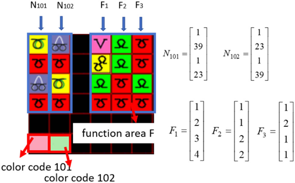
Structure design diagram and corresponding matrix.
3.3 Knitting diagram and threading model
Expand the pattern design diagram based on the number of yarn routes contained in each course of the functional area of the structural design diagram. Each course in the pattern design diagram corresponds to the height of one grid in the expanded design grid. Expand the design grid according to the threading times, and fill it with the same design color as the original grid. For instance, if a course in the pattern design diagram contains two yarns, it will be expanded into two design grids. The final expanded design diagram matrix is M
p = (m
u,v
)
H
,
W
, with a width W and height H as shown in equation (4), where h is the height of the pattern design graph, f
h3,2 is the value of the function area F2, and
The expanded pattern design graph matrix is decomposed according to the pattern colors and replaced with Boolean values. The decomposed expanded pattern design diagram pattern color is replaced with 1, and others are set to 0, obtaining the Boolean matrices for different pattern colors:
The regional structure graph is expanded to match the size of the expanded pattern design graph matrix
The Boolean matrices for different pattern colors are element-wise multiplied with the corresponding pattern color-expanded regional structure graph matrices to obtain the knitting design graph matrix for each pattern color Q
k
= M
k
Summing the knitting design graph matrices for each pattern color gives the knitting design graph matrix

Process of unfolding knitting diagram of (a) diagrammatic process of unfolding knitting diagram and (b) principle of unfolding knitting diagram matrix.
Using the raw material editor, set the raw material code, unit, F number, raw material specification, color, and other information to establish a two-dimensional array S to store raw material information.
Using the yarn threading editor, set the process course, pattern course, knitting status, yarn threading rule, plush height, number of plush threads, number of segments and faces of a single loop model, random deflection angle range of plush, and other parameters. The yarn threading information can be generated based on the expanded knitting design graph information and the structure design graph function area information, or the parameters can be modified as needed. After confirming or modifying the yarn threading information, establish a two-dimensional array E to store the yarn threading information.
4 Geometric model
Weft-knitted fabrics are formed by the lateral connection and longitudinal interlooping of loops, making a single loop the smallest structural unit of knitted fabrics. In 3D simulation of knitted fabrics, a single loop model is first established to represent the basic structural characteristics of the fabric.
In the simulation process of weft-knitted jacquard plush fabric, the main models used are the knitted loop model, float loop model, and plush loop model. Before establishing a single model, an optical microscope can be used to observe the loop form in the actual fabric. According to Peirce’s basic loop model, eight control points are used as the key points, and a 3D ideal loop model structure is simulated using NURBS curves in a clockwise direction. The knitted loop model establishes a 3D coordinate system with the center of the loop root as the origin O, as shown in Figure 5. The loop height is h1, the loop width is w1, and the ideal loop radius is r. The distances of control points P1 to P8 from the y-axis are −w2, −w3, −w4, −w5, w5, w4, w3, w2, and from the x-axis are −h2, 0, h3, h4, h4, h3, 0, −h2. The float loop model connects naturally without setting control points.
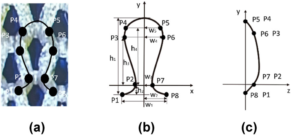
Basic loop model of (a) physical image, (b) front, and (c) side.
Based on the basic loop model, the weft-knitted plush loop model is constructed by moving points P1 and P8 in the positive or negative direction of the z-axis to form the basic plush loop model with an elongated sinker loop effect, as shown in Figure 6. Points P1′ and P8′ are adjacent loops, and L is the plush height, which can be set in the yarn threading editor based on the height of the sinker. This model is suitable for plush yarns with no or low twist. According to the actual situation of plush fabrics, the control points of the plush part are rotated around the x-axis using a rotation matrix to form a plush that lies down in the y-direction. The deflection angle θ can be set in the yarn threading editor based on the height of the sinker or the type of plush yarn, generally between 30° and 60°. For ease of expression, all plush loop models in this text are the forms of plush control points rotated 90° around the x-axis.
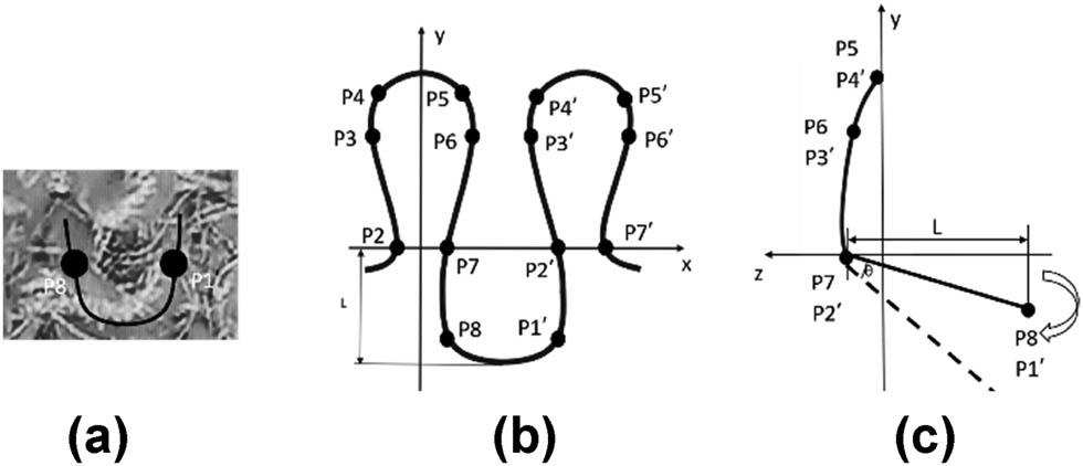
U-shaped plush loop model of (a) physical image, (b) front, and (c) side.
Based on the basic plush loop model, different forms of plush models are established according to the actual state of plush in plush fabrics. Generally, there are two types: O-shaped plush and “8”-shaped plush, mainly related to the height of the sinker, the twist direction of the yarn, and the rotation direction of the plush knitting machine. Usually, when the plush height is higher or when Z-twist yarn is used and the machine rotates clockwise, the plush yarn forms an “8”-shaped loop due to additional twisting during knitting. When the plush height is lower or when using Z-twist yarn and the machine rotates counterclockwise, the loop shape appears as an “O.” This type of loop is generally used for knitting terry cloth. The O-shaped loop model adds four control points to the basic loop model to form a 12-point loop model, as shown in Figure 7. The “8”-shaped loop model adds eight control points to the basic loop model to form a 16-point loop model, as shown in Figure 8.
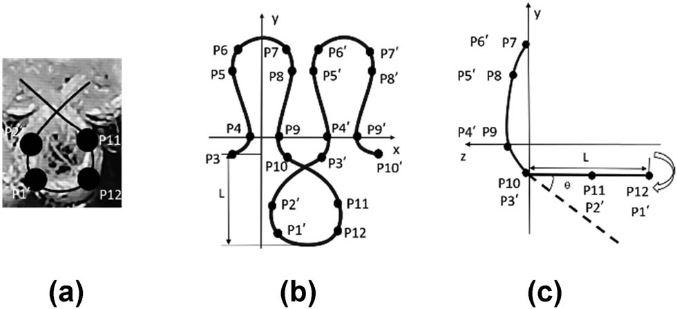
O-shaped plush loop model of (a) physical image, (b) front, and (c) side.

“8”-shaped plush loop model of (a) physical image, (b) front, and (c) side.
Low-twist plush yarns are more likely to untwist after being cut, forming scattered fiber bundles. Thus, a single cut-loop velvet loop model can be established as shown in Figure 9. For each velvet endpoint, the x- and y-coordinates are randomized within a certain range to allow the velvet to spread randomly, with the z-coordinate fixed at the loop height.
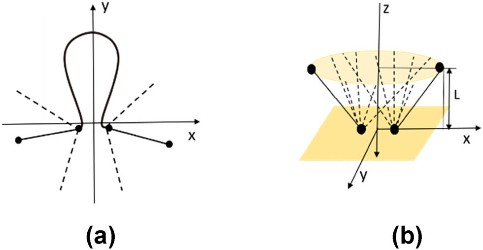
Henkel plush loop model of (a) front and (b) side.
5 Results and discussion
5.1 Generating tubular geometries
The single-loop model from Section 4 is arranged and connected according to the knitting information of each path from the knitting diagram generated in Section 3.3. In the VS2022 programming software, using C# and JavaScript programming languages, the THREE.TubeGeometry method from the Three.js library is used to form a 3D tubular geometry with a radius of r based on all the coordinate points of the loop model. For each path, except for the velvet loop model, the first control point P1 of the first loop model is used as the starting point, and the last control point of the last loop model is the endpoint. The tubes will be connected sequentially from the start point to the endpoint to render the yarn coil entity for the entire course. Henkel plush coils require segmented rendering based on the starting and ending points of each Henkel plush model. Therefore, for each course of Henkel plush coils, multiple tubular geometries must be formed based on the number of Henkel plush threads, with the radius of these geometries corresponding to the thickness of a single Henkel plush thread.
In addition to the radius, tubular geometries have two important parameters: the number of tubular segments and the number of radial segments. The higher the number of tubular segments, the smoother the radial appearance of the tubular coil, as illustrated in Figure 10.
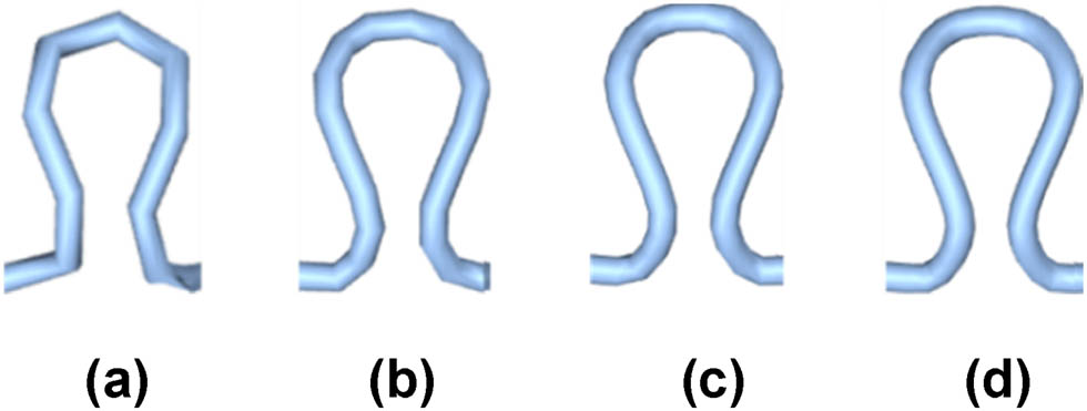
Simulation effect of different tubular segments of (a) 10, (b) 20, (c) 30, and (d) 40.
Similarly, the higher the number of radial segments, the smoother the surface of the coil, as shown in Figure 11.

Simulation effect of different radial segments of (a) 2, (b) 3, (c) 4, and (d) 5.
To achieve good coil shapes, the number of tubular segments and the number of radial segments for the coil model can generally be set to no less than 40 tubular segments and 5 radial segments. However, for Henkel plush models, which require segmented rendering of multiple geometries and significantly increase the simulation rendering time, the number of segments and faces can be reduced to 2 and 4, respectively, due to the smaller radius and linear nature of the Henkel plush tubes. Finally, we use the THREE.Mesh method to create a mesh that combines the previously generated tubular geometries, forming a weft-knitted fabric entity with interlooping effects.
5.2 Establishing the lighting model
To simulate the lighting effects of the fabric in a realistic scenes and reflect the 3D tubular geometry loop stereoscopic and embossed jacquard plush textures, a lighting model is established. Common light sources in Three.js include ambient light, point lights, spotlights, and directional lights. Ambient light has no specific direction and renders all objects in the scene with the same color. It is typically used as a base light source along with other light sources. Through testing, we found that using point lights and spotlights resulted in only parts of the fabric being lit, with many shadowed areas. Using multiple point lights or spotlights could cause some areas to be too bright, obscuring the coil structures. Thus, we ultimately use ambient light and directional light to render the fabric. A 3D coordinate system is established, placing the fabric at the coordinate center, and set multiple directional lights with different directions and intensities. After analyzing and comparing the lighting effects, we set four directional lights with the following positions and intensities (Figure 12):
Directional light1: Position (0,0,1) with intensity 0.7
Directional light2: Position (0,0,−1) with intensity 0.7
Directional light3: Position (−1,1,1) with intensity 0.5
Directional light4: Position (1,−1,1) with intensity 0.5
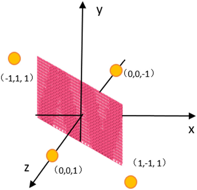
Lighting rendering model diagram.
As shown in Figure 13, the fabric simulation results are rendered by adding different numbers and directions of directional lights on top of the ambient light.
Simulation effect of fabrics in different directions of (a) front and (b) side.
From Figure 13, it can be seen that adding directional lights from different directions can better simulate the shape of the fabric from different directions and the embossed visual effect of the weft-knitted jacquard fabric, with uniform lighting that is not limited by the size of the fabric.
5.3 3D Simulation of weft-knitted jacquard plush
As shown in Figure 14, the 3D simulation flowchart for weft-knitted jacquard plush fabric includes the design principles and simulation methods.
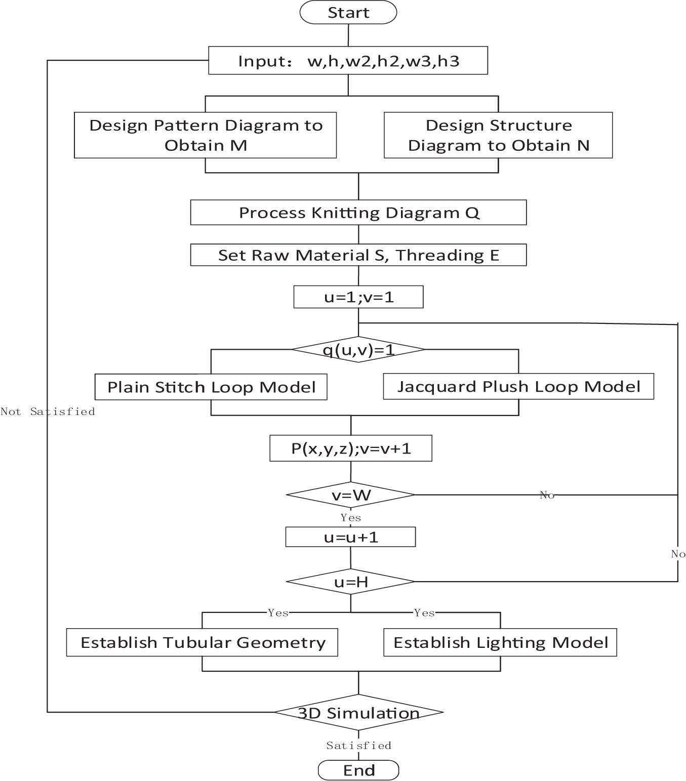
3D simulation flowchart.
Figure 15 depicts a two-color sinker jacquard, using an “8”-shaped plush loop model. According to the knitting design information, the fabric is formed by alternating reverse plush loops and filled yarns, resulting in a horizontal stripe effect on the surface. Each horizontal course is interwoven with plush yarns of different colors. The plush loops have a significant height, allowing them to cover the filled yarn of the subsequent course, thereby creating a pattern effect. Adjusting the tilt angle and height of the plush loops during simulation helps enhance the covering effect, enabling the simulation of three-color sinker jacquard fabrics based on this principle.
3D simulation of two-color sinker jacquard fabric of (a) physical image and (b) simulation image.
Figure 16 shows a sinker relief jacquard plush fabric using an O-shaped plush loop model. The sinker selection creates areas with and without plush loops (plating in non-plush areas), resulting in a relief effect. The plush yarn is made of elastic polyester, and by setting the fineness, number of yarns, and deflection angle range, the natural state of the plush yarn’s shrinkage and spread can be simulated, forming a jacquard plush fabric with a certain nap and relief effect.

3D simulation of weft-knitted relief plush fabric of (a) physical image and (b) simulation image.
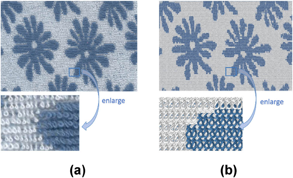
Figure 17 displays an actual image and a 3D simulation of a three-color needle-selective jacquard plush fabric after loop cutting, producing a velvet effect. During simulation, it is necessary to set the number of plush segments, faces, yarns, fineness, and deflection angle range.

3D simulation of velvet fabric of (a) physical image and (b) simulation image.
Figure 18 illustrates a jacquard plush fabric combining sinker selection and needle selection, featuring both relief effects and colors. It primarily uses loop models, floating lines, velvet models, and U-shaped plush loop models. Due to the low twist of the plush yarn, it is prone to untwisting, thus requiring settings for yarn fineness, number, and height.

Jacquard plush fabric combining needle selection and sinker selection of (a) physical image and (b) simulation image.
where area A includes the knitted loop model and float loop model, area B includes the knitted loop model and Henkel plush model, area C includes the knitted loop model and U-shaped plush loop model.
6 Conclusion
This study proposes a design and 3D simulation method for weft-knitted jacquard plush fabrics by studying the knitting principles and structural characteristics of such fabrics.
Based on different knitting methods for plush loops, weft-knitted jacquard plush fabrics are divided into needle-selected jacquard plush fabrics and sinker-selected jacquard plush fabrics. The knitting techniques and morphological characteristics of each type are detailed.
Based on the design principles of weft-knitted jacquard plush, mathematical models for pattern design and structural design were established. These models, derived from the pattern and structure diagrams, formed the basis for the mathematical model of the knitting design graph, including raw material editing and setting of yarn threading parameters. This foundation is crucial for achieving the 3D simulation of weft-knitted jacquard plush fabrics.
Considering the actual morphology of plush loops in fabrics, different geometric models of plush loops were established based on the basic Peirce loop model. These include the U-shaped loop model, velvet plush model, “8”-shaped loop model, and O-shaped loop model.
Utilizing the aforementioned mathematical and geometric models, 3D simulation of jacquard plush fabrics was achieved using WebGL technology. THREE.Tube Geometry from Three.js was used to generate loops, and THREE.Mesh was used to generate the interconnected fabric simulation. In the simulation scene, ambient light and directional light were added to ensure uniform brightness, distinct relief effects, and a more realistic simulation outcome.
In this study, a rapid design method for weft-knitted plush fabrics is proposed through matrix operations and computer programming, achieving 3D simulations of different types of weft-knitted jacquard plush fabrics. This method can improve the efficiency of designers in developing new products and reduce trial-and-error costs. However, using loop models for fabrics like velvet requires rendering each individual fiber, resulting in longer simulation times, and further improvements in simulation speed are needed.
Acknowledgement
The authors acknowledge the financial support provided by “the Fundamental Research Funds for the Central Universities” (JUSRP123005) and the Taihu Zhiguang Science and Technology Research (fundamental research) Project of Wuxi (K20221007).
-
Author contributions: Xiuping Mu proposed a mathematical model for jacquard knitted fabric plush and established geometric models of individual plushes of different types, conducted program code design for three dimensional simulation of plushes through knitting information, and achieved three-dimensional simulation of plush fabric. Gaoming Jiang verified the simulated sample fabrics and carried out the program design of the relevant mathematical models. Songsong Guan developed lighting model code to enhance the realism of fabric simulation. Haisang Liu developed program code for rendering tubular geometric shapes. Li Bingxian conducted comparative analysis of the simulation effects and tested the feasibility of the design method.
-
Conflict of interest: Authors state no conflict of interest.
References
[1] Guo, C., Jiang, G. M. (2014). Computer aided designing system of weft-knitted jacquard plushfabrics. Journal of Textile Research, 35(4):142–147.Suche in Google Scholar
[2] Xu, Y. H., Yuan, X. L. (2005). Design and production of automotive interior fabrics. Shanghai Textile Technology, 33(4):51–53.Suche in Google Scholar
[3] Li Q, Cheng, X, Wang, Y. (2021). Wearing property test and evaluation of weft-knitted plush fabrics, Journal of Beijing Institute of Clothing Technology (Natural Science Edition), 33(4):7–12.Suche in Google Scholar
[4] Cheng, B. L., Jiang, G. M., Zhao, J. J., Li, B. X. (2023). Design and modeling of partial knitting knitted fabric based on matrix transformation. International Journal of Clothing Science and Technology, 35(6):918–937.10.1108/IJCST-06-2022-0085Suche in Google Scholar
[5] Liang, J. L., Cong, H. L., Gao, Z., Zhang A. J., Dong, Z. J. (2020). Computer-aided design of weft-knitted two-side jacquard fabric, International Journal of Clothing Science and Technology, 33(1):122–136.Suche in Google Scholar
[6] Liang, J. L., Cong, H. L., Zhang A. J. (2020). Technical design model of weft-knitted two-side jacquard fabric, Journal of Textile Research, 41(1):69–74.10.1108/IJCST-04-2019-0061Suche in Google Scholar
[7] Hu, H. D., Ke, W., Wei, Z. Y., Deng, Z. M. (2023). 3D simulation of weft-knitted fabric loop model based on opengl improved algorithm, Knitting Industry, 6 (1):29–32.Suche in Google Scholar
[8] Qu, C., Wang, J. Z., Li, B. (2009). Computer 3-D simulation on basic structure of weft-knitted fabrics, Journal of Textile Research, 30(11):136–140.Suche in Google Scholar
[9] Zheng, P. X., Jiang, G. M., Cong, H. L. (2022). Design method of circular weft-knitted jacquard fabric based on jacquard module, Autex Research Journal, 22(2):217–224.10.2478/aut-2020-0062Suche in Google Scholar
[10] Chen, Y. S., Jiang, G. M., Li, B. X. (2022). Design and 3-D simulation of weft-knitted wrap fabric, Journal of Textile Research, 43(12):62–68.Suche in Google Scholar
[11] Shen, Y. L., Dong, Z. J., Cong, H. L. (2022). Structure modeling in three-dimensional simulation of weft-knitted seamless kneepads, Textile Research Journal, 92(3–4):608–617.10.1177/00405175211040872Suche in Google Scholar
[12] Zhang, A. J., Li, X. X., Ma, P. B., Xiong, Y., Jiang, G. M. (2016). 3D simulation model of warp-knitted patterned velvet fabric, International Journal of Clothing Science and Technology, 28(6):794–804.10.1108/IJCST-01-2016-0006Suche in Google Scholar
[13] Zheng, P. X., Jiang, G. M. (2021). Modeling and realization for visual simulation of circular knitting transfer-jacquard fabric, Textile Research Journal, 91(19–20):2225–2239.10.1177/0040517521994497Suche in Google Scholar
[14] Liu, H. S., Jiang, G. M., Dong, Z. J. (2024). Three-dimensional simulation based on mesh modelling for warp-knitted fully-formed garments, International Journal of Clothing Science and Technology, 36(12024):117–131.10.1108/IJCST-09-2021-0122Suche in Google Scholar
[15] Wang, X. F., Cong, H. L., Zhang, A. J. (2013). Computer simulation for warp knitted towel fabric, Journal of Textile Research, 34(5):140–145.Suche in Google Scholar
[16] Cong, H. L., LI, X. L., Zhang, A. J. (2013). Design and 3-D simulation of warp-knitted jacquard towel fabrics, Journal of Textile Research, 34(4):131–136.Suche in Google Scholar
[17] Han, C., Meng, Z., Chen, G. F., Sun, Y. Z. (2009). Three-dimensional simulation of multiple high-low loop tufting carpet, Journal of Textile Research, 30 (9):128–132.Suche in Google Scholar
[18] Han, C., Sun, Y. Z., Chen, G. F., Meng, Z. (2009). Analysis and Simulation on Spatial Structure of Multipile Tufting Carpet, Journal of Donghua University (Natural Science), 35(6):710–715.Suche in Google Scholar
[19] Dai, Z. X., Chen, G. F., Chen, G. (2020). Three-dimensional simulation of multiple high-low loop tufting carpet based on Rhino-Python, Journal of Textile Research, 41(6):69–75.Suche in Google Scholar
[20] Jiang, G. M. (2012). Knitting. Beijing China Textile Apparel Press, Beijing, China, p. 95–98.Suche in Google Scholar
[21] Cheng, S. F., Zhang, B. X., Lei, L., Fan, D. B. (2014). Design and production of one-sided high and low terry fabrics, Advanced Textile Technology, 22(01):38–39.Suche in Google Scholar
© 2024 by the authors, published by De Gruyter
This work is licensed under the Creative Commons Attribution 4.0 International License.
Artikel in diesem Heft
- Characterization of viscoelastic properties of yarn materials: Dynamic mechanical analysis in the transversal direction
- Analysis of omni-channel implementations that are preferred by consumers in clothing sector
- Structural modeling and analysis of three-dimensional cross-linked braided preforms
- An experimental study of mechanical properties and comfortability of knitted imitation woven shirt fabrics
- Technology integration to promote circular economy transformation of the garment industry: a systematic literature review
- Research on T-shirt-style design based on Kansei image using back-propagation neural networks
- Research on She nationality clothing recognition based on color feature fusion with PSO-SVM
- Accuracy prediction of wearable flexible smart gloves
- Preparation and performance of stainless steel fiber/Lyocell fiber-blended weft-knitted fabric
- Development of an emotional response model for hospital gown design using structural equation modeling
- Preparation and properties of stainless steel filament/pure cotton woven fabric
- Facemask comfort enhancement with graphene oxide from recovered carbon waste tyres
- Use of enzymatic processes in the tanning of leather materials
- Optical-related properties and characterization of some textile fibers using near-infrared spectroscopy
- Network modeling of aesthetic effect for Chinese Yue Opera costume simulation images
- Predicting consumers’ garment fit satisfactions by using machine learning
- Non-destructive identification of wool and cashmere fibers based on improved LDA using NIR spectroscopy
- Study on the relationship between structure and moisturizing performance of seamless knitted fabrics of protein fibers for autumn and winter
- Antibacterial and yellowing performances of sports underwear fabric with polyamide/silver ion polyurethane filaments
- Numerical and experimental analysis of ballistic performance in hybrid soft armours composed of para-aramid triaxial and biaxial woven fabrics
- Phonetic smart clothing design based on gender awareness education for preschoolers
- Determination of anthropometric measurements and their application in the development of clothing sizing systems for women in the regions of the Republic of Croatia
- Research on optimal design of pleated cheongsam based on Kano–HOQ–Pugh model
- Numerical investigation of weaving machine heald shaft new design using composite material to improve its performance
- Corrigendum to “Use of enzymatic processes in the tanning of leather materials”
- Shaping of thermal protective properties of basalt fabric-based composites by direct surface modification using magnetron sputtering technique
- Numerical modeling of the heat flow component of the composite developed on the basis of basalt fabric
- Weft insertion guideway design based on high-temperature superconducting levitation
- Ultrasonic-assisted alkali hydrolysis of polyethylene terephthalate fabric and its effect on the microstructure and dyeing properties of fibers
- Comparative study on physical properties of bio-based PA56 fibers and wearability of their fabrics
- Investigation of the bias tape roll change time efficiency in garment factories
- Analysis of foot 3D scans of boys from Polish population
- Optimization of garment sewing operation standard minute value prediction using an IPSO-BP neural network
- Influence of repeated switching of current through contacts made of electroconductive fabrics on their resistance
- Numerical calculation of air permeability of warp-knitted jacquard spacer shoe-upper materials based on CFD
- Compact Spinning with Different Fibre Types: An Experimental Investigation on Yarn Properties in the Condensing Zone with 3D-Printed Guiding Device
- Modeling of virtual clothing and its contact with the human body
- Advances in personalized modelling and virtual display of ethnic clothing for intelligent customization
- Investigation of weave influence on flame retardancy of jute fabrics
- Balloonless spinning spindle head shape optimisation
- Research on 3D simulation design and dynamic virtual display of clothing flexible body
- Turkish textile and clothing SMEs: Importance of organizational learning, digitalization, and internationalization
- Corrigendum To: “Washing characterization of compression socks”
- Study on the promotion multiple of blood flow velocity on human epidermal microcirculation of volcanic rock polymer fiber seamless knitted fabric
- Bending properties and numerical analysis of nonorthogonal woven composites
- Bringing the queen mother of the west to life: Digital reconstruction and analysis of Taoist Celestial Beings Worshiping mural’s apparel
- Modeling process for full forming sports underwear
- Retraction of: Ionic crosslinking of cotton
- An observational study of female body shape characteristics in multiracial Malaysia
- Study on theoretical model and actual deformation of weft-knitted transfer loop based on particle constraint
- Design and 3D simulation of weft-knitted jacquard plush fabrics
- An overview of technological challenges in implementing the digital product passport in the textile and clothing industry
- Understanding and addressing the water footprint in the textile sector: A review
- Determinants of location changes in the clothing industry in Poland
- Influence of cam profile errors in a modulator on the dynamic response of the heald frame
- Quantitative analysis of wool and cashmere fiber mixtures using NIR spectroscopy
- 3D simulation of double-needle bar warp-knitted clustered pile fabrics on DFS
- Finite element analysis of heat transfer behavior in glass fiber/metal composite materials under constant heat load
- Price estimation and visual evaluation of actual white fabrics used for dress shirts and their photographic images
- Effect of gluing garment materials with adhesive inserts on their multidirectional drape and bending rigidity
- Optimization analysis of carrier-track collision in braiding process
- Numerical and experimental analysis of the ballistic performance of soft bulletproof vests for women
- The antimicrobial potential of plant-based natural dyes for textile dyeing: A systematic review using prisma
- Influence of sewing parameters on the skin–fabric friction
- Validation by experimental study the relationship between fabric tensile strength and weave structures
- Optimization of fabric’s tensile strength and bagging deformation using surface response and finite element in stenter machine
- Analysis of lean manufacturing waste in the process flow of ready-to-wear garment production in Nigeria
- An optimization study on the sol–gel process to obtain multifunctional denim fabrics
- Drape test of fully formed knitted flared skirts based on 3D-printed human body posture
- Supplier selection models using fuzzy hybrid methods in the clothing textile industry