Weft insertion guideway design based on high-temperature superconducting levitation
-
Chengjun Zhang
 ,
Chuqiao Xu
,
Chuqiao Xu

Abstract
Wide-width weaving machines typically employ the method of increasing the shuttle’s initial speed to achieve a broader weft insertion. However, this approach not only leads to issues such as significant equipment vibrations, high noise levels, increased energy consumption, and reduced lifespan but also has limitations in achieving substantial increases in the fabric width. The article proposes a wide-width weft insertion method based on high-temperature superconducting magnetic levitation technology. It utilizes the levitation characteristics of high-temperature superconducting shuttles in a permanent magnet array’s magnetic field to levitate the shuttle. The shuttle is then propelled by a traveling wave magnetic field generated by an array of electromagnetic coils, enabling wide-width weft insertion. Based on the required thrust values and weaving speed for the shuttle insertion process, the structural parameters of the weft insertion guideway were calculated. A superconducting suspended weft insertion structure was designed, and a mathematical model between the weft insertion guideway and the shuttle was established. Subsequently, a simulation model of the weft insertion guideway was created using Simulink, and the model was simulated, verified, and analyzed using the field-oriented control algorithm. The simulation results indicate that the operating speed of the levitated shuttle and the driving force for weft insertion meet the requirements for high-speed wide-width weaving.
1 Introduction
Weaving machines are crucial mechanical equipment in textile production, and the fabrics they produce have extensive applications in various fields such as clothing, home textiles, aerospace [1], military defense, rail transportation, marine vessels, hydraulic construction, environmental protection, and so on [2]. Particularly, lightweight and wide carbon fiber fabrics exhibit characteristics such as high strength, high modulus, corrosion resistance, fatigue resistance, and seamless construction [3,4]. When used over large areas, they possess greater overall strength and stability [5]. Currently, it is common practice to increase the weft insertion speed and width of weaving machines by increasing equipment energy consumption and the initial yarn release velocity. Swiss company Sulzer has improved the shuttle-throwing structure by replacing the fixed cam with a rotating cam and optimizing the cam’s motion curve. This modification has reduced the friction between the cam and the shuttle lever, resulting in a 1.7% increase in the efficiency of the shuttle-throwing mechanism [6]. The P730011P shuttle loom machine produced by Swiss company SULTEX (formerly Sulzer Textile) achieves a weft insertion rate of 1570 m/min. The shuttle’s impact force in the weft insertion mechanism is as high as 15 kN/m, and it can produce fabrics with a width of 6.55 m. Rieter Textile Systems improved this machine by reducing the weight of the shuttle using composite materials, resulting in an increased weft insertion initial speed of 40 m/s, which further improved the weft insertion rate. In 1979, Tatsuo Nakatori of Japan proposed an innovative design concept for an electromagnetic weft insertion mechanism. The basic principle of this mechanism includes components such as a power source, a switch, electromagnetic coils, and a guideway that together form an electromagnetic acceleration tube. By controlling the current supplied to the electromagnetic coils, the weft inserter is accelerated due to the electromagnetic forces generated, which allows it to grip and rapidly shoot out the weft yarn along the guideway, effectively increasing the weft yarn’s initial insertion speed. Building upon this concept, researchers both domestically and internationally have conducted further studies on electromagnetic weft insertion. Mirjalili [7] conducted research on the electromagnetic driving force of weaving machine electromagnetic coils, while Owlia et al. [8,9,10,11], from Iran’s Yazd University, built upon this work by using electromagnetic coils to accelerate the ferromagnetic pellets that pull the weft yarn. Through experiments, Owlia studied the projectile launch speed under different parameters of the electromagnetic coil and developed an adaptive neural network model that accurately predicts the projectile speed. Qiao et al. [5] and Xu et al. [12] have designed a multi-stage electromagnetic propulsion system to increase the initial insertion speed of the weft. The conclusion drawn from this research is that to achieve a 6 m wide fabric, the weft inserter’s initial speed must be at least 65 m/s, and for a 12 m wide fabric, the weft inserter’s initial speed needs to be as high as 126 m/s. This innovative design of the electromagnetic weft insertion mechanism offers faster initial insertion speeds compared to traditional mechanical projection or pressure jet insertion methods, allowing the yarn to travel a greater distance within the shuttle space. However, accelerating the warp inserter to extremely high speeds in a short period results in excessive acceleration for both the inserter itself and the tensioned yarn, leading to severe fluctuations in yarn tension and causing warp thread breakage issues [13,14]. This is especially problematic in the production of lightweight and wide-width fabrics, as the high acceleration can cause fine yarns to break, limiting the variety of wide-width fabrics that can be produced using this method.
In summary, there are still some challenges in the current methods for increasing the width of weaving machines. Increasing fabric width has limitations, and excessively high initial speeds also significantly increase the risk of weft breakage. Therefore, this article proposes a method for achieving magnetic levitation high-speed wide-width weft insertion using electromagnetic coils to propel high-temperature superconducting shuttles. This method involves using toothed cores, electromagnetic coils, and permanent magnet arrays on both sides to create the weft insertion guideway, with permanent magnets and high-temperature superconductors forming the main components of the shuttles. The article calculates the dimensions of the electromagnetic coil-propelled guideway and the high-temperature superconducting shuttles, establishes a mathematical model for the guideway and shuttles, and conducts simulation calculations, yielding satisfactory results.
2 High-temperature superconducting levitation weft insertion structure
2.1 Guideway structure
The high-temperature superconducting levitation weft insertion system consists of the weft insertion guideway and the shuttle, as illustrated in Figure 1. The weft insertion guideway is composed of a toothed iron core, winding, and levitated permanent magnet arrays on both sides of the iron core. High-temperature superconducting blocks on both sides are stabilized above the permanent magnet arrays of the weft insertion guideway using the Meissner effect. The shuttle’s weft insertion drive consists of alternating magnetic poles in a permanent magnet arrangement fixed at the center of the shuttle casing. The shuttle casing is made of carbon fiber material. There are cavities on both sides of the shuttle casing for securing high-temperature superconductors and storing liquid nitrogen.
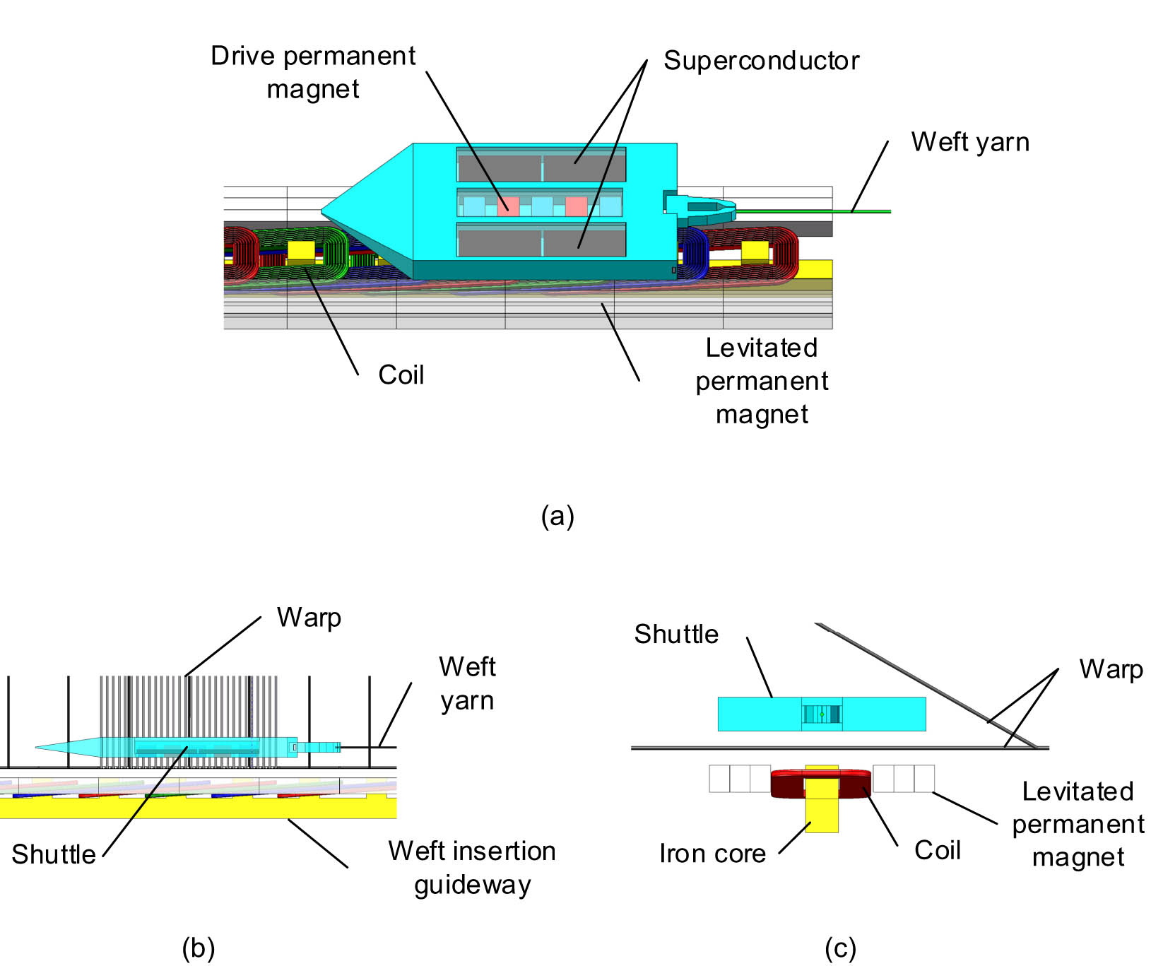
Schematic diagram of weft insertion guideway structure: (a) top view, (b) front view, and (c) side view.
2.2 Winding selection
When the shuttle is levitated on the guideway to perform weft insertion, the angle of the warp shed between the upper and lower warp threads is small, and space is limited. Therefore, the winding on the core utilizes a more space-efficient method known as the short-distance double-layer stacking winding method [15], with the winding filling the slots in the core, as shown in Figure 2.
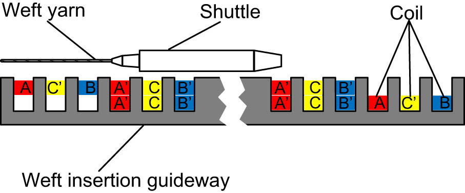
Winding filling method.
The winding connection method is shown in Figure 3.
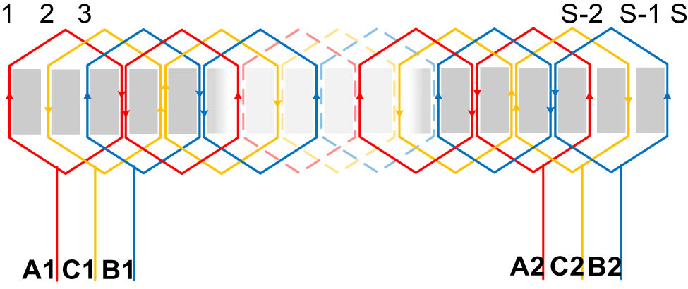
Winding connection method.
In Figure 3, the total number of slots on the core is represented as S, and the magnetic pole pair number is denoted as p = S/6. Each coil of the winding spans across two core slots, and the center-to-center spacing between two adjacent magnetic poles spans across three core slots. Additionally, under each magnetic pole, the three-phase coils A, B, and C each occupy one slot in the stator. In other words, the winding pitch is denoted as y = 2, the pole pitch is denoted as
3 Design of the weft insertion guideway
3.1 Analysis of the weft insertion guideway drive force
In wide-width weft insertion, the shuttle is propelled by the driving force of the weft insertion guideway, pulling the weft yarn to achieve weft insertion. The force analysis of the shuttle and the weft yarn during this process is depicted in Figure 4.
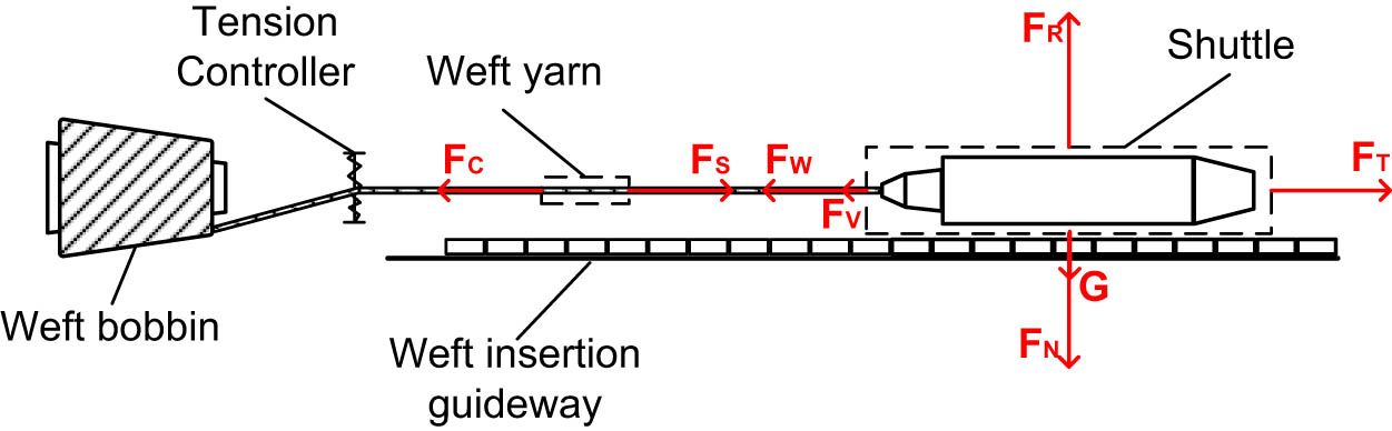
Analysis of forces on shuttle and weft yarn.
In Figure 4, F C represents the clamping force from the tension controller at the starting end of the weft insertion guideway, and F S is the traction force exerted by the levitated shuttle. F W and F V, respectively, denote the tension in the yarn and the viscous frictional force acting on the shuttle during its flight. F T represents the traction force from the weft insertion guideway. In the vertical direction, the shuttle’s own downward gravity G and the normal force F N balance against the upward levitation force from the superconductor F R.
The shuttle’s weft insertion motion can be divided into two stages: the acceleration stage and the constant-speed stage. In the acceleration stage, the traction force F T exerted on the shuttle by the electromagnetic weft insertion guideway can be represented as follows:
In the constant-speed stage, F T can be represented as follows:
where M
S is the shuttle’s mass,
In the context of textile engineering, due to the significantly greater mass of the itself compared to the mass of the weft yarn during the acceleration process, the mass of the weft yarn can be neglected during this time period. Furthermore, since there is no direct contact between the shuttle and the weft insertion guideway, the viscous frictional force generated by lubricating oil in traditional motor structures, as indicated in the study of Cheng and Thomas [16], can be disregarded in this context. Thus, equation (1) can be simplified to
In the constant-speed stage, the traction force
where l represents the length of the weft yarn and
Due to the clamping force from the tension compensator at the starting end of the weft insertion guideway, the curvature of the weft yarn during the weft insertion process is very small, and the angle between its two ends and the horizontal line can be neglected. Thus, equation (4) can be simplified to
The itinerary of the designed weft insertion guideway is denoted as 10 m, the maximum running speed of the shuttle on the guideway as V
S = 10 m/s, and the mass of the shuttle as M
S = 2 kg. In order to reduce the acceleration distance and increase the utilization of the weft insertion guideway, it is necessary to appropriately increase the magnitude of the acceleration. A higher acceleration of the shuttle during the acceleration phase results in greater strain on the weft yarn, making it more susceptible to breakage [17]. Particularly when producing lightweight textiles, the settings for the clamping force of the tension compensator and the acceleration of the shuttle during its acceleration phase are of paramount importance. In this study, we have selected F
C = 20 N,
3.2 Calculation of weft insertion guideway parameters
The design of the weft insertion guideway is based on reference to a permanent magnet synchronous linear motor [18], and its main structural dimension calculation formula is as follows (Figure 5):
where b
e is the width of the two teeth at the edge of the iron core,
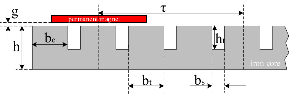
Structural dimension weft insertion guideway.
The design criteria for the weft insertion guideway are presented in Table 1.
Weft insertion guideway design raw data sheet
| Parameters | Numerical values |
|---|---|
| Startup electromagnetic thrust (N) | 120 |
| Level flight electromagnetic thrust (N) | 20 |
| Voltage supply (V) | 220 |
| Number of power supply phases (phases) | 3 |
| Power supply frequency (Hz) | 50 |
| Maximum shuttle operating speed (m/s) | 10 |
| Stroke (m) | 10 |
Based on formulas (7)–(10) and in conjunction with the design criteria for the permanent magnet synchronous linear motor, the structural parameters of the weft insertion guideway are calculated as shown in Table 2.
Weft insertion guideway structure parameter table
| Parameters | Numerical values | Parameters | Numerical values |
|---|---|---|---|
| τ (mm) | 100 | h t (mm) | 10 |
| 2p | 100 | b s (mm) | 8 |
| L (m) | 10.056 | S | 300 |
| 2a (mm) | 9.6 | Number of turns per phase (turns) | 2,250 |
| h (mm) | 20 | g (mm) | 1 |
| b t (mm) | 25.3 | m s (kg) | 2 |
3.3 Drive permanent magnet and shuttle sizes
During the weft insertion process, the levitation force provided by the superconductor to the shuttle is greatly influenced by environmental factors such as temperature. This leads to variations in the air gap thickness between the shuttle and the weft insertion guideway. To meet the performance requirements of the weft insertion process, it is essential to maximize the magnetic flux as much as possible.
The equivalent magnetic circuit diagram of the weft insertion guideway and the drive permanent magnets [19] is shown in Figure 6. Let the width of the drive permanent magnets be b m = 0.75τ and the length l = 2a.
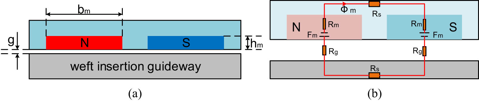
Equivalent magnetic circuit diagrams of the weft insertion guideway and drive permanent magnets: (a) structural schematic and (b) equivalent magnetic circuit diagram.
The magnetic flux
where F m is the magnetic potential of the drive permanent magnets, R m is the magnetic resistance of the drive permanent magnets, and R r is the magnetic resistance of the weft insertion guideway iron core.
The magnetic potential of the drive permanent magnets is proportional to its thickness, given by F m = kh m, where k is the magnetic performance parameter of the permanent magnet material. Since the magnetic permeability of the permanent magnet material is close to that of a vacuum, both can be combined when calculating the magnetic resistance. Simultaneously, the magnetic resistance of the weft insertion guideway is neglected. Therefore, equation (11) can be expressed as follows:
where
From equation (12), it can be concluded that after determining the dimensions of the weft insertion guideway, the magnitude of the magnetic flux
Let
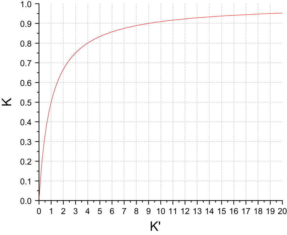
K and K′ relationship diagram.
From Figure 7, it can be observed that the magnetic flux
Accordingly, when the gap thickness g = 1 mm, the thickness of the permanent magnets can be determined as 5 mm. Six permanent magnets are used in the shuttle as driving magnets, with a pole pitch of t between them. Taking into account the original thickness of the shuttle casing and the space reserved for the installation of superconductors, the three-dimensional dimensions of the shuttle can be determined as 80 mm × 300 mm × 10 mm.
4 Modeling of the weft insertion guideway drive system
4.1 Mathematical model of weft insertion drive
In the d–q coordinate system, the voltage equation of the weft insertion guideway is given by the following equation:
where u
d
is the d-axis voltage, u
q
is the q-axis voltage, R
S is the stator resistance, i
d
is the d-axis current, i
q
is the q-axis current,
The magnetic flux equation in the d–q coordinate system is as follows:
where
The electromagnetic thrust equation is as follows:
where F represents the thrust of the weft insertion guideway.
The motion equation of the weft insertion guideway is as follows:
where B is the coefficient of viscous friction, M
Y is the mass of the weft yarn,
4.2 Weft insertion guideway drive model
Based on the mathematical model of the weft insertion guideway, we have established a simulation model in Simulink [21]. The control diagram is depicted in Figure 8.
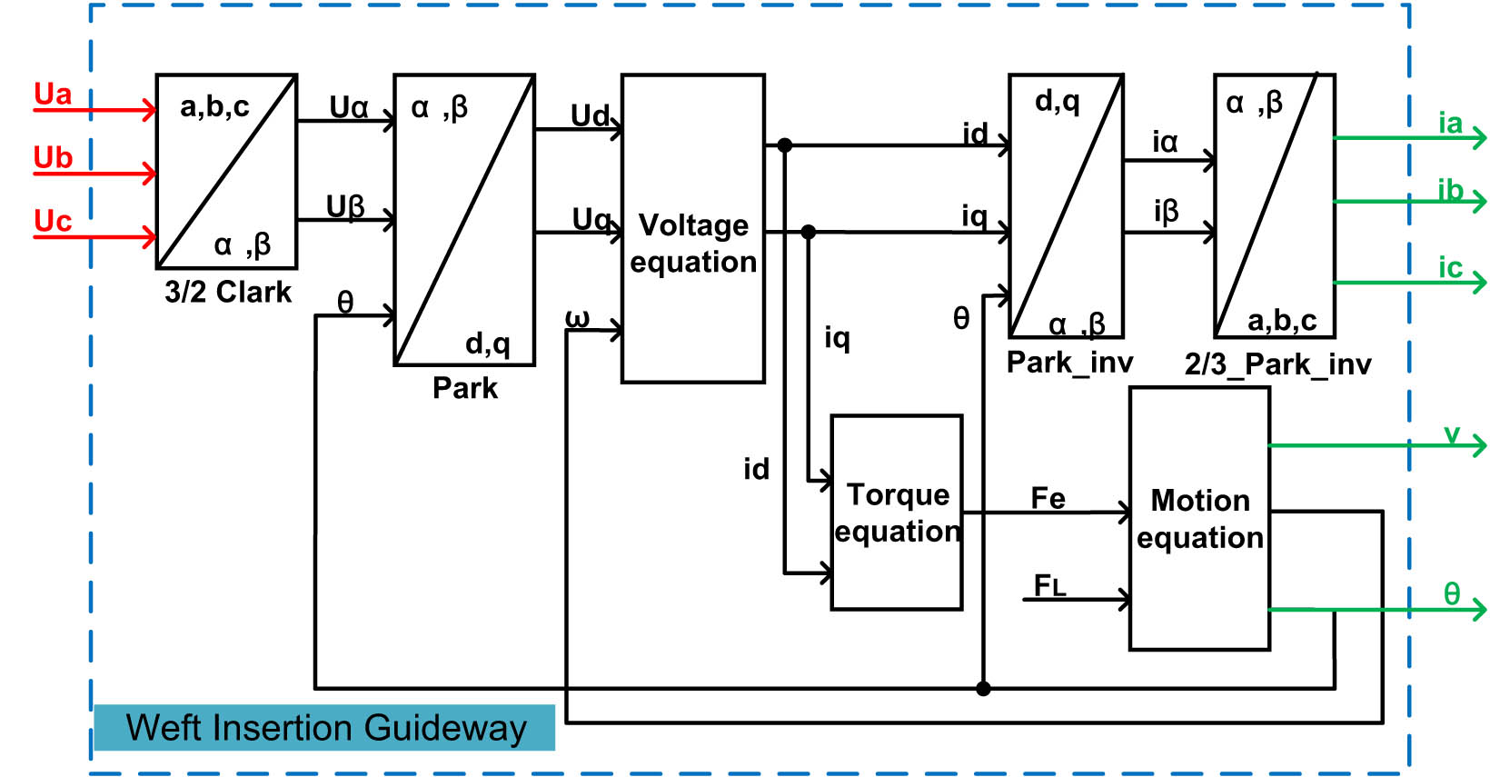
Weft insertion guideway control block diagram.
In this model, by inputting three-phase voltages (U a, U b, U c) and the clamping force at the output end F L, and setting the structural parameters of the weft insertion guideway, after conducting simulation calculations, we can obtain real-time weft insertion guideway state parameters. These parameters include three-phase currents (i a, i b, i c), thrust, shuttle speed, displacement, and electrical angle, among others.
4.3 Control system model
The overall control system structure diagram is illustrated in Figure 9, which includes components such as the weft insertion guideway model, inverter, and space vector pulse width modulation.
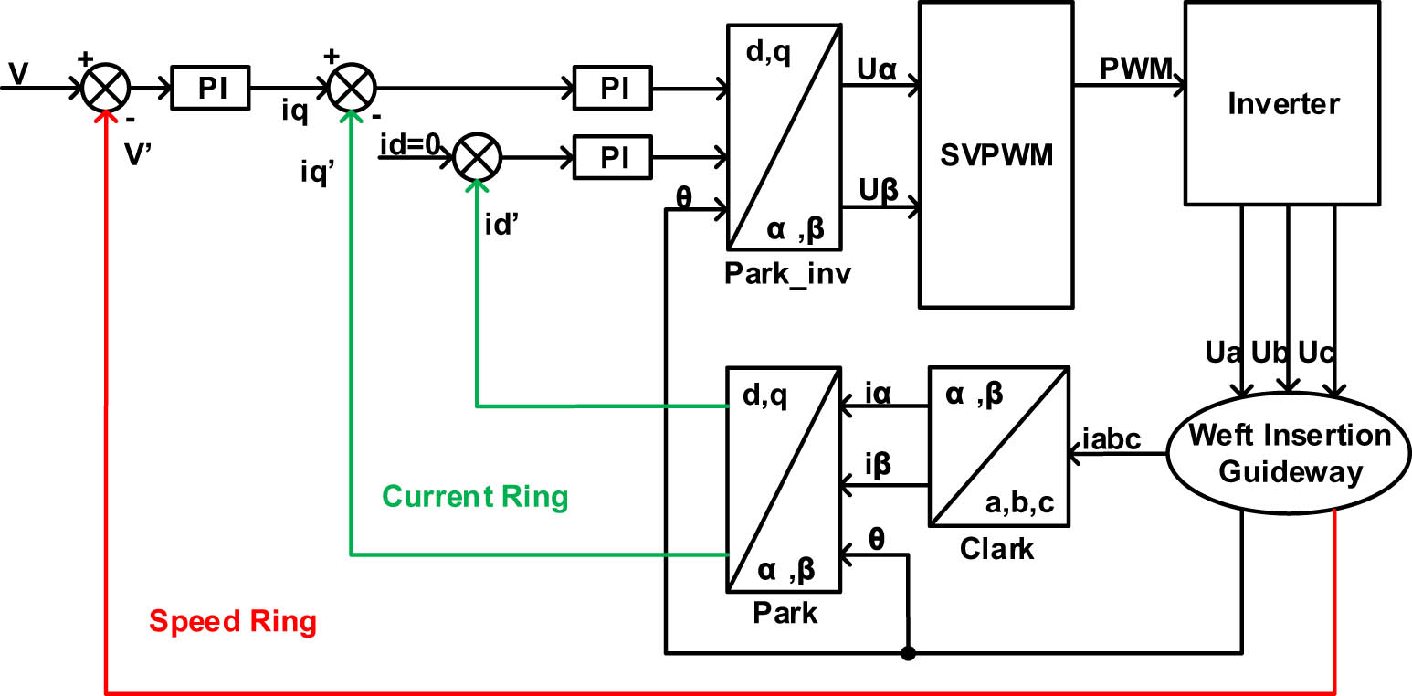
Control system structure block diagram.
We have implemented field-oriented control as the motion control method for the weft insertion guideway. This control strategy includes two current loops and one velocity loop, all of which utilize proportional integral controllers to generate reference current vectors or voltage vectors [22]. To minimize the generation of reluctance torque, the current loop section utilizes i d = 0 control mode.
5 Simulation analysis
To verify the accuracy of the above weft insertion guideway model and its control methods, we conducted a simulation analysis. The parameters for the weft insertion guideway are configured as shown in Table 3.
Weft insertion guideway simulation parameter settings
| Parameters | Numerical values |
|---|---|
| Voltage (V) | 220 |
| Power frequency (Hz) | 50 |
| Shuttle mass (kg) | 2 |
| Yarn thread density (kg/m) | 0.038 |
| Viscous friction coefficient | 0.1 |
| Exit line-end clamping force (N) | 20 |
We conducted simulations for both no-load ( F L = 0 N, ρ = 0 kg/m) and loaded (F L = 20 N, ρ = 0.038 kg/m) conditions, with a total simulation duration of 1.2 s. The main data are depicted in Figure 10.
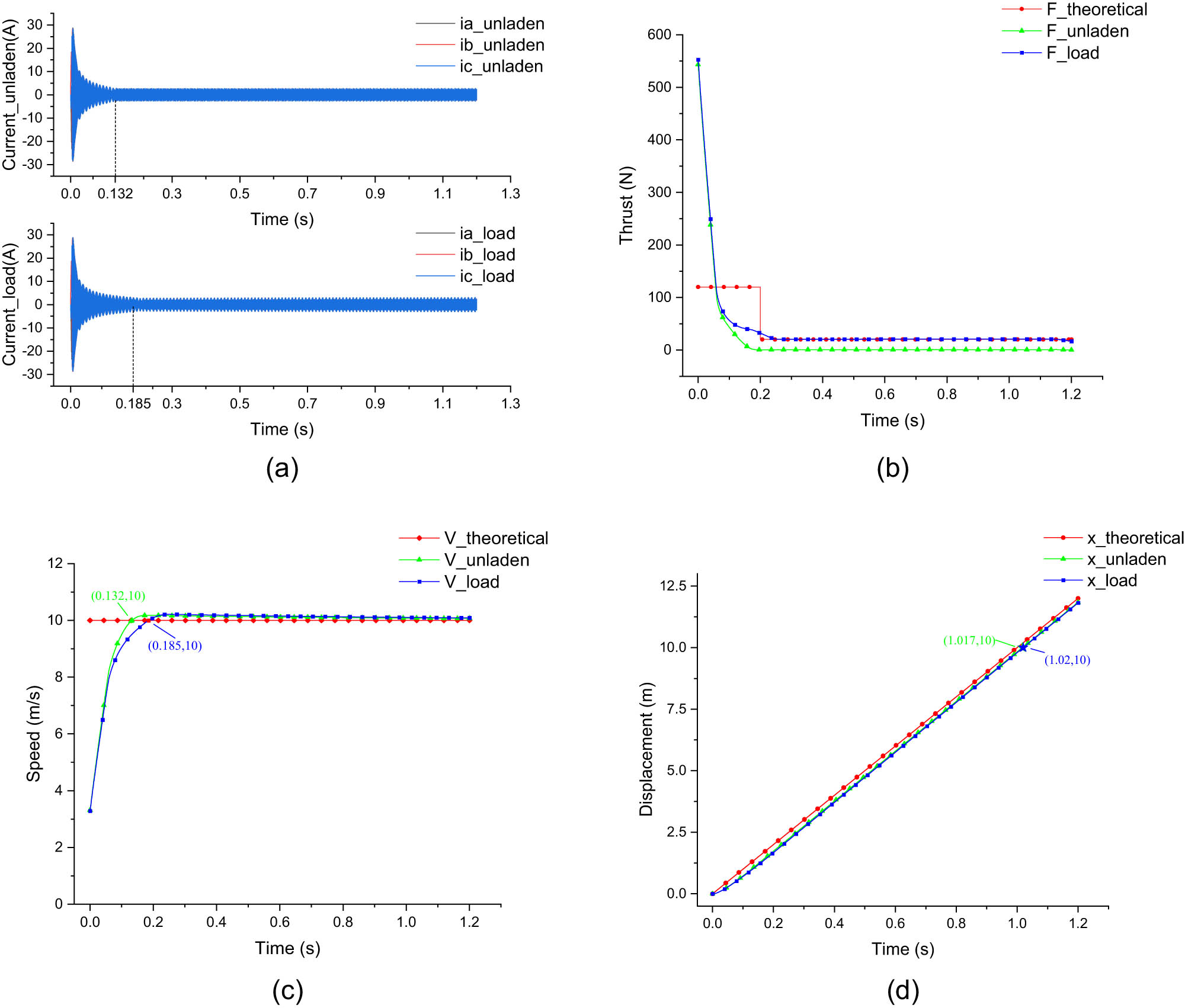
Simulation results of the main data graph: (a) current, (b) thrust, (c) speed, and (d) displacement.
During the no-load startup, the current at the moment of startup is 28.5 A, and it subsequently stabilizes at 2.7 A within 0.132 s. The average thrust during the acceleration phase is 161.4 N, with an acceleration of 80.7 m/s². It reaches the constant velocity phase after 0.132 s, with an average thrust of 1.05 N, which is greater than 0 N. This is because during the constant velocity phase, the shuttle has to overcome frictional forces. At the same time, the shuttle’s velocity reaches 10 m/s and gradually approaches 10 m/s after 0.132 s, with a displacement of 10 m reached at 1.017 s.
During the loaded startup, the current at the moment of a startup is 30.27 A, and it subsequently stabilizes at 3.09 A within 0.185 s. The average thrust during the acceleration phase is 123.9 N, with an acceleration reaching 51.28 m/s². These values are 3.9 N and 1.28 m/s² higher than the theoretical values but still meet the requirements for weft insertion with low-strength yarn. After 0.185 s, the shuttle enters the constant velocity phase with an average thrust of 20.91 N, which is greater than the clamping force of 20 N at the exit end. This is because, during the constant velocity phase, the shuttle not only has to overcome the clamping force at the exit end and the viscous frictional force but also has to overcome the increasing tension in the weft yarn due to the continuous increase in length and mass of the weft yarn. At the same time, the shuttle’s velocity reaches 10 m/s and gradually approaches 10 m/s after 0.185 s, with a displacement of 10 m reached at 1.02 s, equivalent to a weft insertion rate of 600 m/min on the loom.
6 Conclusions
This article presents a weft insertion method based on high-temperature superconducting magnetic levitation and designs the structure of the weft insertion guideway. The weft insertion guideway utilizes a traveling magnetic field generated by electromagnetic coils when alternating current is applied to drive the shuttle’s flight and weft insertion. Simultaneously, it utilizes the levitation force of high-temperature superconductors to overcome both the shuttle’s own gravity and the normal force from the electromagnetic coils.
In order to design the structure of the weft insertion guideway, the article first calculated various structural parameters of the weft insertion guideway based on the technical specifications of the weft insertion process in the weaving machine. Next, a mathematical model of the weft insertion guideway-shuttle-weft yarn system was established, and a simulation model was built in Simulink for conducting simulations. The simulation process included no-load simulations, where the weft insertion guideway only drove the shuttle’s flight motion, and loaded simulations, where the weft insertion guideway drove the shuttle to carry the weft yarn for weft insertion. The simulation results closely matched the theoretical values, indicating the correctness and effectiveness of this weft insertion guideway structure. This has significant implications for the manufacturing of fast and wide-width looms.
Acknowledgments
This work was supported by the National Natural Science Foundation of China (Project No. 51875414), Wuhan Applied Basic Frontier Project (2022013988065209), and Wuhan Knowledge Innovation Special Project (2023010201010115).
-
Conflict of interest: The authors declare that the research was conducted in the absence of any commercial or financial relationships that could be construed as a potential conflict of interest.
-
Data availability statement: No new data were created or analyzed in this study. Data sharing does not apply to this article.
References
[1] Cherston, J., Veysset, D., Sun, Y., Yano, H., Nelson, K. A., Murari, S., et al. (2020). Large-area electronic skins in space: vision and preflight characterization for first aerospace piezoelectric e-textile. In Sensors and smart structures technologies for civil, mechanical, and aerospace systems 2020 (pp. 239–252). SPIE. 10.1117112.2557942.Suche in Google Scholar
[2] Daria, M., Krzysztof, L., Jakub, M. (2020). Characteristics of biodegradable textiles used in environmental engineering: A comprehensive review. Journal of cleaner production, 268, 122129. 10.1016/j.jclepro.2020.122129.Suche in Google Scholar
[3] Liu, Y., Zwingmann, B., Schlaich, M. (2015). Carbon fiber reinforced polymer for cable structures – A review. Polymers, 7, 2078–2099. 10.3390/polym7101501.Suche in Google Scholar
[4] Zhang, C.J., Liu, Y., Peng, Y., Wang, Y., Li, C.Y., Zuo, X.Y., et al. (2024). Insertion Performance Study of an Inductive Weft Insertion System for Wide Weaving Machines. Applied Sciences-Basel, 14, 2687. 10.3390/app14072687.Suche in Google Scholar
[5] Qiao, X., Shunqi, M., Xiaoyu, Y., Islam, M. M., Zhen, C., Shaojun, W., et al. (2019). Analysis of the magnetic field and electromagnetic force of a non-striking weft insertion system for super broad-width looms, based on an electromagnetic launcher. Textile Research Journal, 89, 4620–4631. 10.1177/0040517519839371.Suche in Google Scholar
[6] Markus, G. (2014). Gripper head for the insertion of weft threads on a gripper weaving machine. Patent US8875747(B2).Suche in Google Scholar
[7] Mirjalili, S. A. (2005). Using electromagnetic force in weft insertion of a loom. Fibres & Textiles in Eastern Europe, 13, 67–70.Suche in Google Scholar
[8] Owlia, E., Mirjalili, S. A. (2021). The effect of launcher parameters on the projectile velocity in laboratory electromagnetic weft insertion system. Journal of The Textile Institute, 112, 1232–1239. 10.1080/00405000.2020.1808384.Suche in Google Scholar
[9] Owlia, E., Mirjalili, S. A., Shahnazari, M. (2019). Design and modeling of an electromagnetic launcher for weft insertion system. Textile Research Journal, 89, 834–844. 10.1177/0040517518755793.Suche in Google Scholar
[10] Owlia, E. (2023). Optimization of the projectile velocity in electromagnetic weft insertion system by genetic algorithm. Journal of The Textile Institute, 114, 364–370. 10.1080/00405000.2022.2037830.Suche in Google Scholar
[11] Owlia, E., Mirjalili, S. A. (2021). Simulation of the electromagnetic weft insertion system by adaptive neuro fuzzy interface system. Journal of The Textile Institute, 112, 1359–1366. 10.1080/00405000.2020.1815409.Suche in Google Scholar
[12] Xu, Q., Cui, X., Mei, S., He, Y., Chen, Z., Meng, F. (2022). Structural performance optimization design of continuously accelerating electromagnetic weft insertion system. Applied Sciences-Basel, 7, 12. 10.3390/app12073611.Suche in Google Scholar
[13] Hossain, M. M., Hossain, N., Naim, A. S., Ghosh, G. (2020). Thread breakage in modern loom and efficiency. International Journal of Current Science Research and Review, 2, 24–35. 10.47191/ijcsrr/V2-i4-01.Suche in Google Scholar
[14] Gulcan, S., Mine, A., Halil, R. A., Recep, E., et al. (2011). Warp tension distribution over the warp width and its effect on fabric’s breaking strength distribution over the fabric width in woven fabrics. Tekstil ve Konfeksiyon, 21, 36–41.Suche in Google Scholar
[15] Guohai, L., Hongtao, Z. (2008). Design and analysis on permanent-magnet BLDC motor for automatic door. Proceedings of the 11th International Conference on Electrical Machines and Systems (pp. 397–402). Wuhan, Hubei, China.Suche in Google Scholar
[16] Cheng, G., Thomas, H. (2023). Design and experimental analysis of an ultra-high speed switched reluctance machine with aerostatic bearings. IEEE Transactions on Transportation Electrification, 9, 2255–2266. 10.1109/tte.2022.3222481.Suche in Google Scholar
[17] Marques, F. A., Cabeço Silva, E., Cabeço Silva, A., Drean, J. Y. (2004). Tensile properties and fracture morphology of viscose yarn at high strain rates. Textile Research Journal, 74, 551–554. 10.1177/004051750407400615.Suche in Google Scholar
[18] Haixing, W., Haichao, F., Xiaozhuo, X., Jikai, S. (2013). Modeling analysis and parameters calculation of permanent magnet linear synchronous motor. Journal of Computers, 8, 463–470. 10.4304/jcp.8.2.463-470.Suche in Google Scholar
[19] Mao, Y., Sun, Z., Zhou, W., Zhuang, Z., Qian, H. (2021). Electromagnetic design of toroidal permanent magnet linear synchronous motor. IEEE Access, 9, 98005–98012. 10.1109/access.2021.3095912.Suche in Google Scholar
[20] Qian, J., Zhao, C., Pan, N., Xie, T. (2021). Design and performance analysis of permanent magnet linear synchronous motor. Journal of Intelligent and Fuzzy Systems, 40, 7811–7818. 10.3233/jifs-189602.Suche in Google Scholar
[21] Dabin, Z., Jiwen, H., Xinjin, W., YaPing, Z., Xibin, G. (2017). Model and performance study on the PMLSM. 43rd Annual Conference of the IEEE-Industrial-Electronics-Society (IECON) (pp. 3670–3675). Beijing, Peoples R China.Suche in Google Scholar
[22] Ana-Maria, P., Marius, P. D. (2022). Adaptive cruise control in electric vehicles with field-oriented control. Applied Sciences-Basel, 12, 7094. 10.3390/app12147094.Suche in Google Scholar
© 2024 by the authors, published by De Gruyter
This work is licensed under the Creative Commons Attribution 4.0 International License.
Artikel in diesem Heft
- Characterization of viscoelastic properties of yarn materials: Dynamic mechanical analysis in the transversal direction
- Analysis of omni-channel implementations that are preferred by consumers in clothing sector
- Structural modeling and analysis of three-dimensional cross-linked braided preforms
- An experimental study of mechanical properties and comfortability of knitted imitation woven shirt fabrics
- Technology integration to promote circular economy transformation of the garment industry: a systematic literature review
- Research on T-shirt-style design based on Kansei image using back-propagation neural networks
- Research on She nationality clothing recognition based on color feature fusion with PSO-SVM
- Accuracy prediction of wearable flexible smart gloves
- Preparation and performance of stainless steel fiber/Lyocell fiber-blended weft-knitted fabric
- Development of an emotional response model for hospital gown design using structural equation modeling
- Preparation and properties of stainless steel filament/pure cotton woven fabric
- Facemask comfort enhancement with graphene oxide from recovered carbon waste tyres
- Use of enzymatic processes in the tanning of leather materials
- Optical-related properties and characterization of some textile fibers using near-infrared spectroscopy
- Network modeling of aesthetic effect for Chinese Yue Opera costume simulation images
- Predicting consumers’ garment fit satisfactions by using machine learning
- Non-destructive identification of wool and cashmere fibers based on improved LDA using NIR spectroscopy
- Study on the relationship between structure and moisturizing performance of seamless knitted fabrics of protein fibers for autumn and winter
- Antibacterial and yellowing performances of sports underwear fabric with polyamide/silver ion polyurethane filaments
- Numerical and experimental analysis of ballistic performance in hybrid soft armours composed of para-aramid triaxial and biaxial woven fabrics
- Phonetic smart clothing design based on gender awareness education for preschoolers
- Determination of anthropometric measurements and their application in the development of clothing sizing systems for women in the regions of the Republic of Croatia
- Research on optimal design of pleated cheongsam based on Kano–HOQ–Pugh model
- Numerical investigation of weaving machine heald shaft new design using composite material to improve its performance
- Corrigendum to “Use of enzymatic processes in the tanning of leather materials”
- Shaping of thermal protective properties of basalt fabric-based composites by direct surface modification using magnetron sputtering technique
- Numerical modeling of the heat flow component of the composite developed on the basis of basalt fabric
- Weft insertion guideway design based on high-temperature superconducting levitation
- Ultrasonic-assisted alkali hydrolysis of polyethylene terephthalate fabric and its effect on the microstructure and dyeing properties of fibers
- Comparative study on physical properties of bio-based PA56 fibers and wearability of their fabrics
- Investigation of the bias tape roll change time efficiency in garment factories
- Analysis of foot 3D scans of boys from Polish population
- Optimization of garment sewing operation standard minute value prediction using an IPSO-BP neural network
- Influence of repeated switching of current through contacts made of electroconductive fabrics on their resistance
- Numerical calculation of air permeability of warp-knitted jacquard spacer shoe-upper materials based on CFD
- Compact Spinning with Different Fibre Types: An Experimental Investigation on Yarn Properties in the Condensing Zone with 3D-Printed Guiding Device
- Modeling of virtual clothing and its contact with the human body
- Advances in personalized modelling and virtual display of ethnic clothing for intelligent customization
- Investigation of weave influence on flame retardancy of jute fabrics
- Balloonless spinning spindle head shape optimisation
- Research on 3D simulation design and dynamic virtual display of clothing flexible body
- Turkish textile and clothing SMEs: Importance of organizational learning, digitalization, and internationalization
- Corrigendum To: “Washing characterization of compression socks”
- Study on the promotion multiple of blood flow velocity on human epidermal microcirculation of volcanic rock polymer fiber seamless knitted fabric
- Bending properties and numerical analysis of nonorthogonal woven composites
- Bringing the queen mother of the west to life: Digital reconstruction and analysis of Taoist Celestial Beings Worshiping mural’s apparel
- Modeling process for full forming sports underwear
- Retraction of: Ionic crosslinking of cotton
- An observational study of female body shape characteristics in multiracial Malaysia
- Study on theoretical model and actual deformation of weft-knitted transfer loop based on particle constraint
- Design and 3D simulation of weft-knitted jacquard plush fabrics
- An overview of technological challenges in implementing the digital product passport in the textile and clothing industry
- Understanding and addressing the water footprint in the textile sector: A review
- Determinants of location changes in the clothing industry in Poland
- Influence of cam profile errors in a modulator on the dynamic response of the heald frame
- Quantitative analysis of wool and cashmere fiber mixtures using NIR spectroscopy
- 3D simulation of double-needle bar warp-knitted clustered pile fabrics on DFS
- Finite element analysis of heat transfer behavior in glass fiber/metal composite materials under constant heat load
- Price estimation and visual evaluation of actual white fabrics used for dress shirts and their photographic images
- Effect of gluing garment materials with adhesive inserts on their multidirectional drape and bending rigidity
- Optimization analysis of carrier-track collision in braiding process
- Numerical and experimental analysis of the ballistic performance of soft bulletproof vests for women
- The antimicrobial potential of plant-based natural dyes for textile dyeing: A systematic review using prisma
- Influence of sewing parameters on the skin–fabric friction
- Validation by experimental study the relationship between fabric tensile strength and weave structures
- Optimization of fabric’s tensile strength and bagging deformation using surface response and finite element in stenter machine
- Analysis of lean manufacturing waste in the process flow of ready-to-wear garment production in Nigeria
- An optimization study on the sol–gel process to obtain multifunctional denim fabrics
- Drape test of fully formed knitted flared skirts based on 3D-printed human body posture
- Supplier selection models using fuzzy hybrid methods in the clothing textile industry