Study on wall-slipping mechanism of nano-injection polymer under the constant temperature fields
-
Donglei Liu


Abstract
Polyphenylene sulfide (PPS) and copper (Cu) were used as the polymer and substrate material to simulate the nano-injection molding process by molecular dynamics method. The results show that the PPS chain obeys Einstein’s diffusion law in the early stage of injection molding then deviates from it in the late stage due to the entanglement and limitation of surrounding nanoparticles. In addition, the process of conformational isomerization of polymer chains is accompanied by the twisting and stretching of fixed chains. There are two kinds of adhesion phenomena, one is the macromolecular slides violently in small areas of some sure nanoscale groove to form multiple anchor points. The other case involves multiple nano-grooves along the metal interface, the polymer chain slides and is bolted as multiple anchors in different grooves due to the exerted wall-drag effect on the neighboring chains. These two slipping and anchoring mechanisms are consistent with de Gennes’ slipping theory. Through the quantitative analysis of the influence of pressure on injection filling, it is found that injection pressure should be kept within a certain range to achieve the positive effect of molding.
1 Introduction
Nano-injection molding, one of the key development directions of polymer/metal composite molding technology (1–3), has been extensively applied due to its high efficiency and reliability, high-grade and personalized molding quality, and wide molding range (4–7). Nano-injection molding is used in many high-tech integrated micro–macro processing fields such as the automotive industry, optoelectronic technology, and micro–nano manufacturing (8,9). In this method, surface treatment of the metal substrate consists of preparing nano-scale grooves with different characteristics, which are then filled with a polymer material to form physical anchors. Once the polymer is cured, the metal and the polymer are tightly connected (10).
During industrial injection molding, the polymer undergoes the normal stress, and the shear flow which occurs in contact with metal (11,12). In this respect, studying the shear flow phenomenon in the polymer injection molding process is helpful to produce engineering structural parts of polymer/metal composite materials with lightweight and high strength, conforming to the market demand (13). Once polymers are injected, they tend to fill the nanoscale grooves on the metal substrate so as to be tightly bonded with hard metal.
Before nano-injection molding, the pre-formed metal substrate needs to be treated to form a structure with micro–nano pit characteristics (14,15). The pits are then filled with a polymer material through the injection molding process to form physical anchors (graft chains), whose subsequent solidification allows one to realize the close connection between polymer and metal (16–18). Many scholars have done a series of studies on nano-injection and shear flow. Zhou et al. (19,20) proposed PMMA/nickel metal cavity interface model with rectangular nano-grooves to establish the effects of polymer molecular weight and nano-groove size on the filling efficiency of polymer materials in the microstructure of the mold interface. Pranov et al. (21) incorporated PC into the nano-cavity and assumed that the injection or compression molding polymer microstructure is closely related to the interfacial adhesion energy. Masato et al. (22) investigated the influence of mold cavity on the filling flow resistance during thin-wall injection molding, showing that the smaller the interaction energy at the polymer/mold interface, the higher the drag reduction rate, and the higher the wall slip speed. Yang et al. (23) studied the interface structure and dynamic behavior of confined polymer melt systems with various molecular structures under shear flow and found that polymers with different molecular structures would affect the relationship between wall slip and shear rate. Kadoya et al. (24) observed the filling depth of polybutylene terephthalate on the surface of the aluminum substrate under different injection speed conditions, concluding that the filling depth was greatly affected by the injection speed. Weng et al. (25) constructed nano-cavities with different aspect ratios and injected polymethyl methacrylate polymer therein with the aim of analyzing the dynamic stress changes during the flow process. According to the results, the stress in the above system was induced by the compression and entanglement of molecular chains under the restriction of flow pressure and cavity wall. As the aspect ratio increased, the stress also increased. Kimura et al. (26) presented the metal–plastic direct joining through the two basic processes: a surface treatment forming nanostructures and an insert injection molding. It was found that the joining strength positively correlated with cavity pressure conditions, whereas the adhesion performance showed a negative correlation with the injection speed.
In the previous research (27–30), polyphenylene sulfide (PPS) and Al were used as the base materials to build a multi-layer simulation model of the Al layer, PPS layer, and vacuum layer of the “V”-shaped pole, and the effect of temperature and pressure on the adhesion performance was analyzed as well (27). An optimal temperature window was established, and the higher injection pressure was found to be beneficial in improving the adhesion performance. On this basis, in order to investigate the interaction and anchoring behavior of PPS/Cu nano-injection molding interfaces, four different nanopit shapes were afterward constructed to elucidate the effect of interface morphology on injection filling, and the results showed that the polymer was more easily injected into nanopits with beveled or rounded boundaries, such as cylindrical and conical interfaces (28). In addition, PPS, PA6, iPP, Al, and Cu were used as experimental substrates to deeply study the influence of different materials on the filling efficiency and adhesion properties. Among them, PA6 and PPS were more suitable for molding on Al and Cu substrates, showing the better filling and adhesion properties than iPP (29).
In view of this, the aim of this article was to investigate the shear flow behavior of PPS/Cu in the process of nano-injection. By establishing a PPS/Cu nano-injection interface model with nano-grooved structure, simulating the effects of positive pressure and transverse shear stress, the mechanism of polymer chain injection molding and shear slip was discussed, and the theoretical model of de Gennes was verified. The optimal injection pressure window was obtained by studying the bonding between polymer and metal. In particular, multi-pit modeling was used to study the adhesion mechanism and molecular shear flow pattern at the interface between polymer and metal matrix from the perspective of injection pressure and size through computational simulation.
2 Model and simulation
2.1 Interface and model construction
PPS is an organic polymer consisting of sulfide-linked aromatic rings, i.e., modules of repeating units (–C6H4–S) (27). Initially, considering the molecular weight and material density of PPS, the monomer model of single-chain PPS was established. Then an appropriate polymer structure with a degree of polymerization of 20 and the number of chains of three was simulated according to the experimental requirements. The initial structural density was set at 1.36 g‧cm−3 and the initial temperature was 298 K for structural optimization and simulated annealing. After six cycles of annealing, the final annealing temperature was 573 K, the internal energy of the system tended to be basically stable, and the non-bonding energy (van der Waals energy) was kept at a very small level, so that the unreasonable structure could be eliminated. After the above-mentioned geometric optimization, annealing, and relaxation, the polymer model basically reached equilibrium. Based on the size of the polymer model, a face-centered cubic lattice copper atomic model was constructed, followed by a unit model with a size of 4.6 nm × 4.6 nm × 4.0 nm. A (100) crystal plane was selected as the upper surface, and two inverted “V”-shaped grooves with a bottom length of 1.8 nm and a height of 1.3 nm were cut. Then a heterointerface model including PPS, Cu, and vacuum layers was established. The thickness of the vacuum layer was 3 nm, which was larger than the intermolecular cutoff radius of 15.5 Å used to avoid the contact between the bottom metal and the upper layers, eliminating periodicity in the Z direction. The perspective view and actual size of the model are given. The model was re-optimized, and the entire modeling process is shown in Figure 1.

Overview structure of the PPS/Cu interface model.
2.2 Simulation details
In order to study the interfacial adhesion and shear flow between the polymer and the metal matrix during the nano-injection process, the all-atom simulation method was adopted, and several comparative experiments were carried out. The first group of trials consisted of investigating the effect of the pressure direction on the motion of the polymer, as shown in Figure 2. Each total pressure was 600 bar, the total pressure was controlled to remain unchanged, and the total pressure was decomposed into the component pressure in the three directions of the coordinate system, which enabled people to reduce the error caused by pressure damage (31) in the actual process. The second group consisted of elucidating the effect of different magnitudes of pressure on the polymer flow behavior (Figure 3).
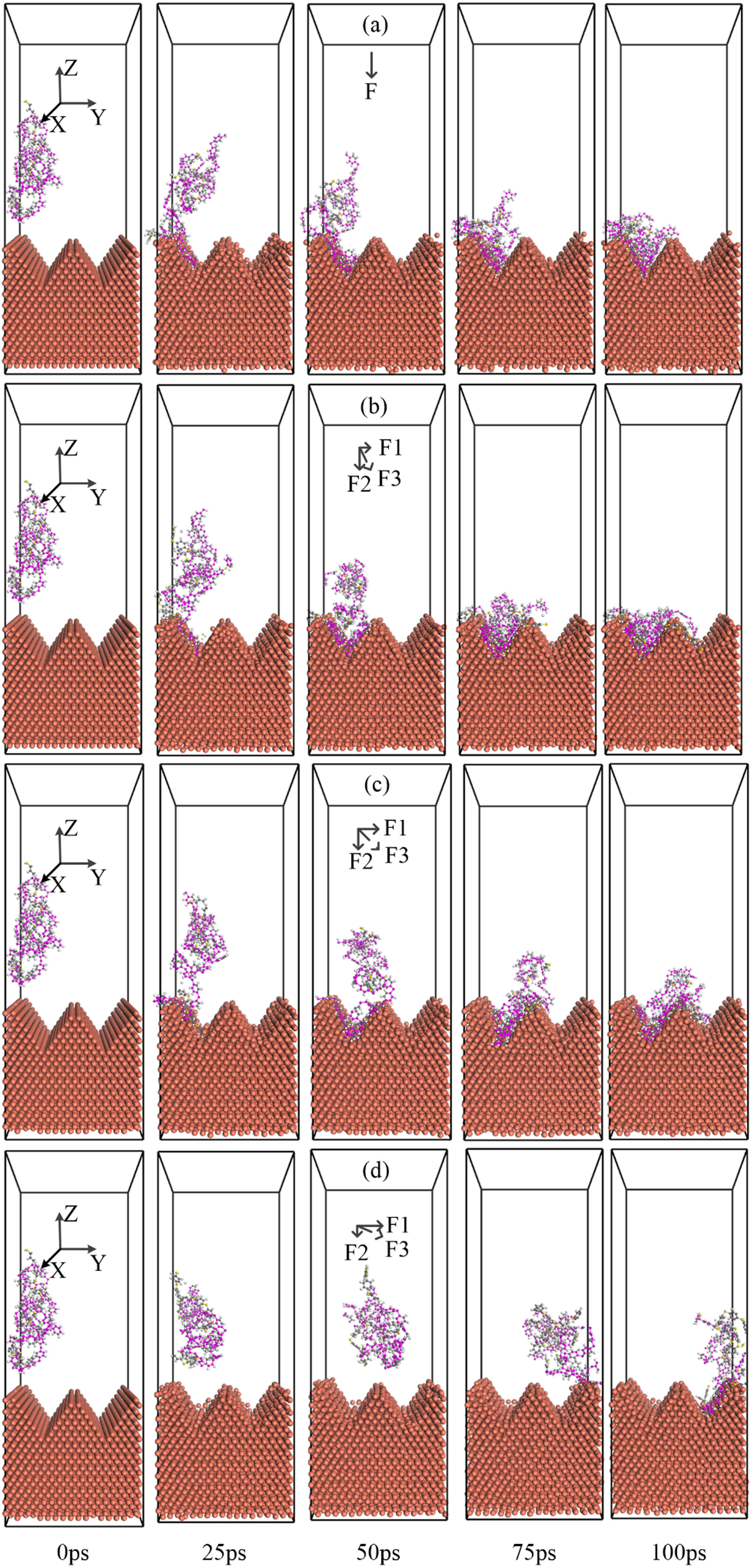
Snapshot configurations of metal–polymer systems in molding under different direction forces. The angle indicates the angle with the negative direction of the Z-axis: (a) 0°, (b) 22.5°, (c) 45°, and (d) 67.5°.
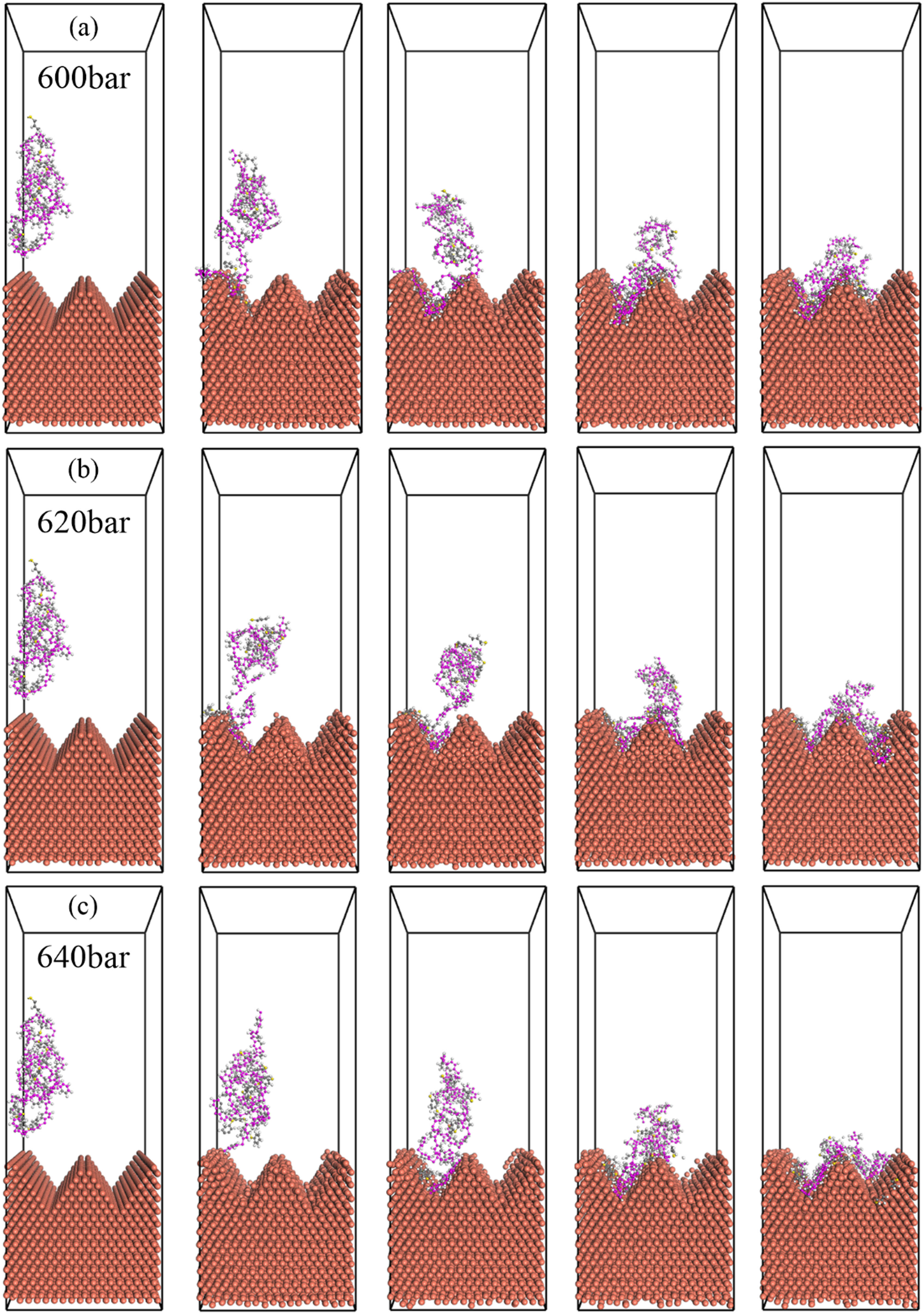
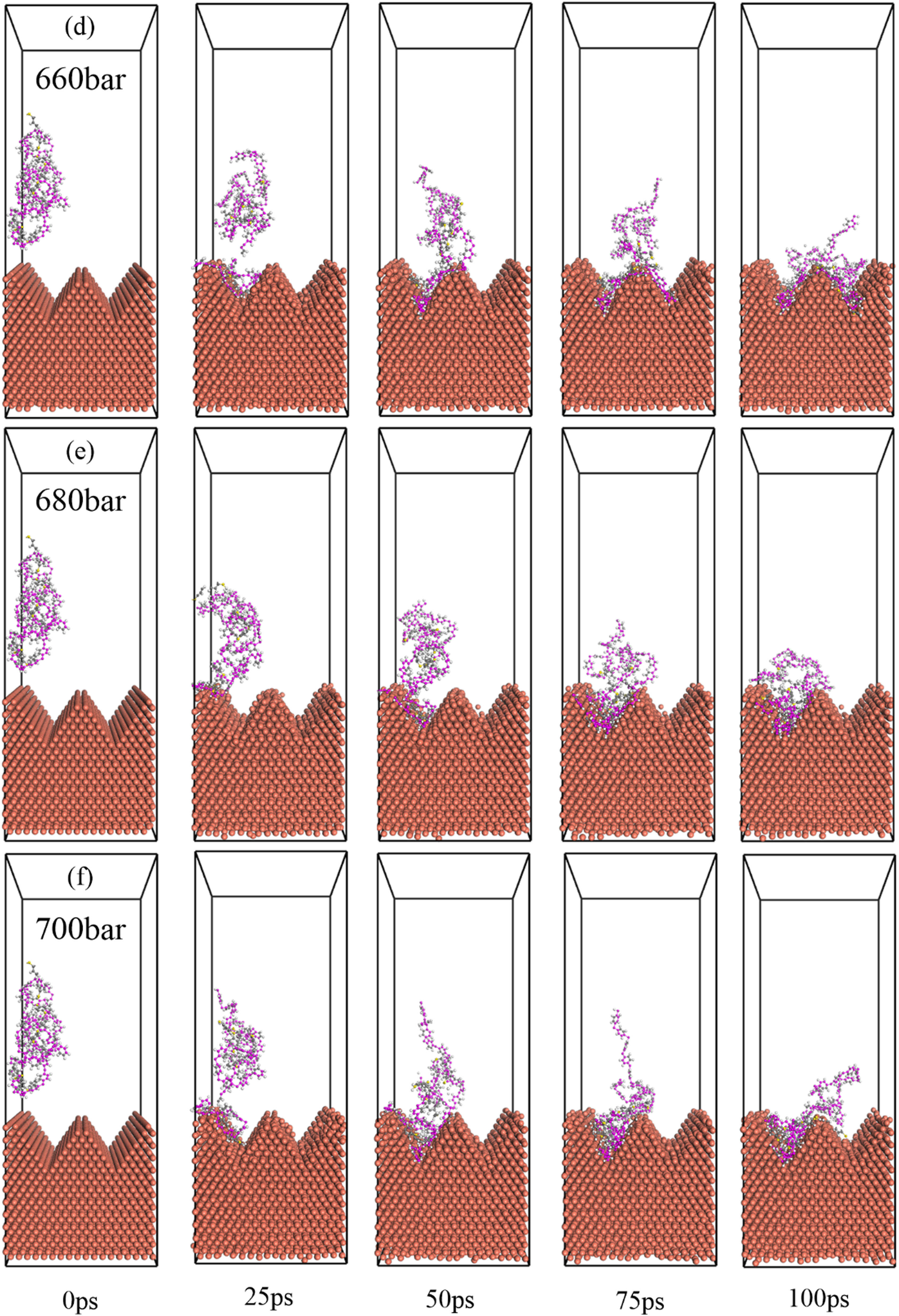
Snapshot of metal–polymer forming process under different pressures (injection angle of 45°): (a) 600 bar, (b) 620 bar, (c) 640 bar, (d) 660 bar, (e) 680 bar, and (f) 700 bar.
To prevent the influence of error caused by the energy mode at different stages of the experiment, the initial model was geometrically optimized and energy-minimized according to a Smart method (27). In order to gain a deeper understanding of the factors affecting the lateral sliding of the polymer chain, multiple sets of simulation experiments were carried out by setting up the resultant pressure gradient within a reasonable injection pressure range. In the molecular dynamics simulation system, the preheat temperature of PPS was controlled. At the same time, given the difference in thermal conductivity between polymer and metal and the instantaneousness of the actual filling behavior, the temperature of metal was set to be consistent with that of polymer. To make the simulation more realistic, the model was defined based on the three-dimensional periodic boundaries to extend infinitely in the X and Y directions (horizontal directions), whereas the Z direction (vertical direction) was not disturbed by the upper (far) macromolecules. The three-dimensional periodic boundaries enabled the barrier effect of the vacuum layer to more truly reflect the filling behavior of the polymer interface layer at the metal pit interface. On this basis, the filling process was programmed whereby the NVT ensemble (N is the number of molecules, V is the volume, and T is the temperature) in the system remained unchanged, while the direction of the resultant pressure was controlled by adjusting the pressure in each direction. This allowed one to observe the effect of transverse shearing of the polymer and to acquire a sufficient amount of data. A COMPASS force field commonly used for the complex systems such as polymers and metals (32) was applied in this study. Materials Studio (MS) simulation software was used to simulate the nano-injection molding process. The Andersen method (33) was employed for temperature control and simulation of the static properties of the interface. The Berendsen method (33) served as the pressure control tool for selecting anisotropic and isotropic systems, and the molecular dynamics integration was based on the Velocity Verlet algorithm (34). The atom-based model (35) was used to calculate the non-bonded interactions, and Ewald summation (36,37) was applied to calculate the Coulomb forces.
After the preprocessing of the metal/polymer models was completed, a nano-injection molding simulation with 100,000 iteration steps was performed on each set of models. In order to simulate the process of polymer shear flow, the magnitude of the pressure applied in the negative Z direction and the positive Y direction was controlled by varying the angle of the pressure. To establish the influence of the pressure on the injection and filling of the polymer, the injection pressure angle was selected as 45°, and the magnitude of the pressure in the negative Z direction and the positive Y direction was adjusted so that the resultant pressure changed within a reasonable gradient range. The total simulation time is 100 ps, a set of data is obtained every 1 ps, and the simulation data is extracted every 25 frames for analysis.
3 Results and discussion
3.1 Interface bonding and shearing
In the actual injection molding process, there are various directions of injection pressure, these different directions of pressure cause the polymer configuration change and shear flow behavior in the process of movement. The simulation process in this study was divided into two stages: one was the free diffusion process before the polymer contacted the metal, and the other was the movement process on the metal surface. For a more intuitive and clearer observation of the filling and shear flow phenomena during injection molding, the pressures were applied parallel to the Z-negative directions and Y-positive directions of the selected polymer chains. The simulation process is shown in Figure 2a–d, in which a gradient of 25 ps has been used to demonstrate the change in the interface binding over time, the angles are vertical, 22.5°, 45°, and 67.5°, respectively. As can be seen from the figure, during the nano-injection molding, the polymer chains slid along the matrix wall and filled the dimples, which led to the sliding behavior of the wall surface (38). Besides, there was the obvious deformation between shear chains and dynamic unfolding effect, the polymer along the metal wall is adsorbed on the wall, slowly slides down the metal wall, and has a dragging effect on the adjacent chains. In the filling stage all polymers enter the groove, after the filling stage is complete, the polymer is further compressed, until the simulation terminates. Under the action of the pressure, frictional resistance was created between the polymer and the metal substrate, which induced a clipping field therein.
In addition, according to molecular dynamics and statistical mechanics, the filling and anchoring behavior of polymer materials substrate grooves due to the particle diffusion inside the polymer under the action of an external field. In the ensuing time, the driving pressure that makes external particles enter the groove by diffusion and transition essentially disappears. Because of the “soft matter” of polymer materials, this diffusion process is accompanied by random walks of particles on the chains caused by the molecular and orientation stress. As shown in Figure 2a, the polymer chains under a positive pressure slide along the metal wall, filling the entire groove. Thanks to the spatial size of the controlled nanocavity and the flow resistance during the shear flow of the polymer, there was an obvious deformation effect between the shear chains, which made the shear flow of the polymer more obvious, so that the polymer was adsorbed by the metal wall, and the wall generated huge friction resistance, which made the movement of the whole polymer chain more intense. Figure 2b–d displays the change in the injection pressure in the Y-positive direction. As the pressure increases, so does the polymer’s range of motion. As a result, the part that was in contact with the metal wall generated huge frictional resistance, while the contact-free part moved to the right groove under the action of pressure, being limited by the regions that were put in touch with each other. However, since the entire simulated system was under periodic boundary conditions (39), the polymer chains exposed to the large pressure in the Y-direction were continuously shearing and sliding in the horizontal direction. At the same time, the polymer chains were undergoing severe orientation deformation, spreading from their initial shape toward the metal wall, as shown in Figure 2b and c. Moreover, an anchor point formed after the polymer contact with the metal, and the uncontacted part was displaced from the left to the right groove to the right groove until it was completely bonded to the metal wall. The too-large pressure in the Y-direction led to the situation shown in Figure 2d, whereby the polymer was directly bonded to the right wall of the right groove without any contact with the metal.
It can be observed from Figure 2 that an injection angle of 45° can better satisfy the bonding effect. To further investigate the adhesion properties in the polymer motion, a reasonable molding process was afterward modeled by setting the direction of the injection pressure to 45°. Figure 3 depicts a schematic diagram of the injection molding under different working pressures (from 600 to 700 bar). Initially, the polymer chains were randomly distributed before contacting the metal wall, and the contact wall was sliding along the wall, exhibiting a wall-slip effect (40). Since the direction of the pressure was tilted by 45°, the macromolecule started to move under the injection pressure. The chain came into contact with the groove on the left, creating an anchoring effect and friction that hindered the movement of the macromolecule. Therefore, the polymer chain that was not in contact with the metal acquired resistance. The macromolecule’s further movement was affected by the injection pressure and the friction of the metal wall and the pulling between the chains. Thus, when the polymer was combined with a part of the metal, the movement of the entire chain became more difficult. The subsequent spreading of the polymer chains without contact with metal was like the tear-slip and twisting process of the fixed chain, which was also consistent with de Gennes’ theory (41). The only difference was that the model in the present study was limited by the interface characteristics, so that the polymer chain exhibited a specific movement trend, spreading along the shape of the groove in the lateral pressure and the pulling of the polymer chain. The polymer chains will shear transversely along the metal wall, exhibiting a shear-thinning effect until the end of the simulation time (42). As shown in Figure 3a–f, the polymer chains bonded to the metal wall within 0–25 ps, indicating that free diffusion had been completed and the subsequent complex motion would be restricted by the metal wall. Once the pressure increased (Figure 3a–d) and the polymer chain entered in contact with the groove, the uncontacted polymer was more likely to squeeze into the groove on the right to achieve more effective anchoring and stronger bonding effect. As shown in Figure 3e and f, it was more difficult for the polymer chains to get into the appropriate grooves than before. This is because the initial pressure becomes larger, so does the vertical pressure, resulting in greater friction. At this time, when the macromolecule was combined with the metal wall, a great frictional resistance was generated. Even if a lateral pressure moving to the right, it is not enough to move the polymer chains from the groove on the left to the groove on the right. According to Figure 3f, a small amount of polymer chain entered the right groove, but most remained in the left groove. This also showed that excessive pressure was not conducive to the filling and shearing of polymer chains.
3.2 Diffusion mechanism
In the nano-injection molding process, the injection-filling behavior of polymers is actually the diffusion process of macromolecules. Polymer chains were randomly selected to investigate the diffusion behavior of polymers further. Figure 4a and b shows the motion process of the chains under different process conditions. Figure 4a displays the trajectory of the polymer chain under the vertical pressure, and Figure 4b depicts the trajectory under the 45° direction pressure. While having the same initial position, the trajectories in both figures were moving randomly under different pressures. As shown in Figure 4, the polymer chain in the initial stage was displaced continuously and rapidly into the grooves of the substrate under the injection pressure and the drag of the polymer chain. Furthermore, it was limited by various factors such as nano-cavity, polymer entanglement, internal friction, dynamic shear deformation, and elastic recovery. It could quickly squeeze into the groove and generate a small area of friction but also continued to creep under the action of pressure. In contrast, the possibility of movement after polymer–metal bonding in Figure 4a was very small, due to the influence of the metal interface structure and the pressure direction. In Figure 4b, the polymer–metal bonding creates a small shear field, and the positive Y-direction pressure tends to shift to the right. As shown in the figure, the soft polymer material slowly spread along the metal interface. This process of motion binds the polymer tightly to the metal, creating anchor points, while the polymer chain slides through different grooves and is bolted in place, consistent with de Gennes’ theory (41). During bonding with the metal interface, some atoms were confined to a small range to move randomly, while others diffused into the correct grooves until the system reached dynamic equilibrium.
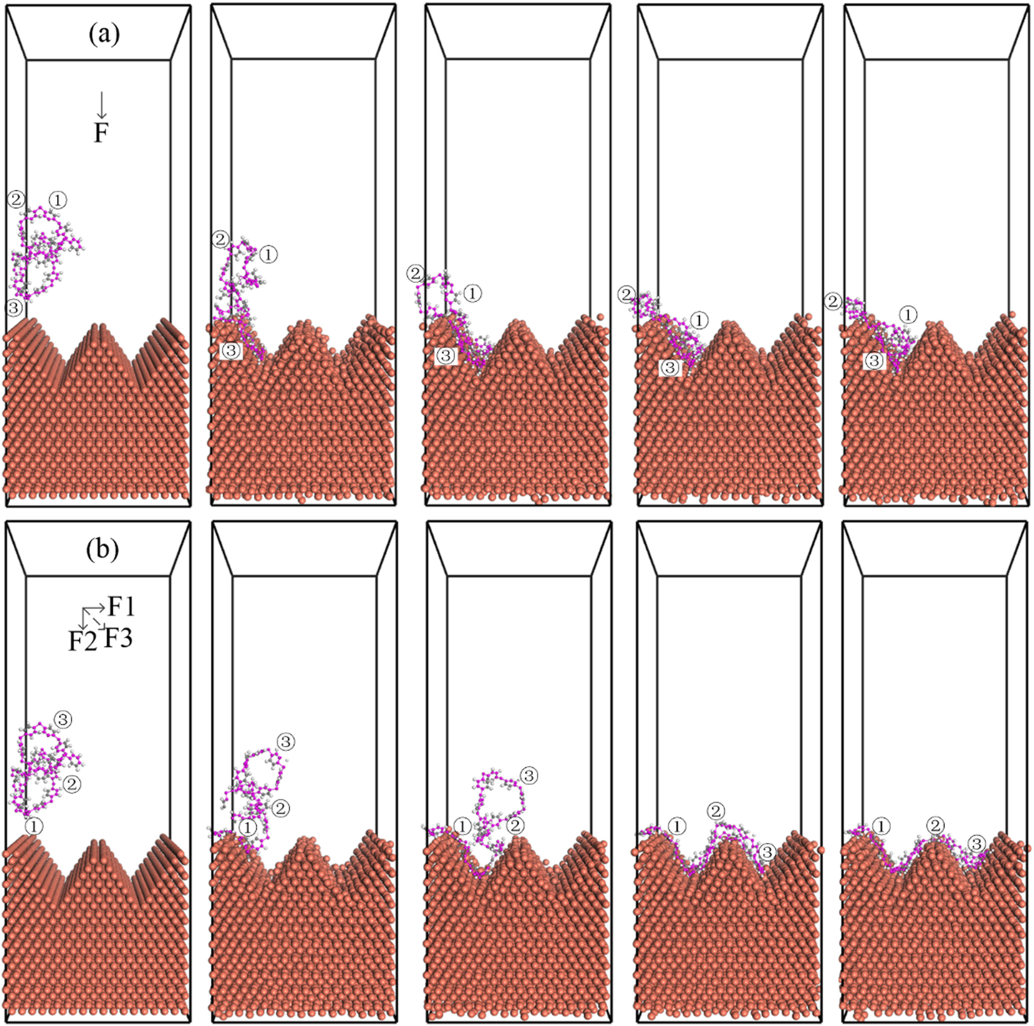
The motion trajectory of the single chain under different process conditions: (a) injection angle of 0° and (b) injection angle of 45°.
Figure 4a shows the trajectory of a single chain under the Z-negative direction pressure. It could be seen that the motion trajectory of the polymer chain under the action of the vertical pressure was restricted in the groove on the left. It first slid into the groove along the left wall and then moved toward the left groove all the time due to the subsequent friction, extrusion, and stress of the polymer chain. Meanwhile, it could not diffuse from the left to the right wall. As seen from Figure 4a, the polymer chain was quickly injected into the left groove, combined with the metal wall, and then slowly slid down the metal wall; in turn, the carbon atoms were pulled by the chain and restrained, being able to move in a small range until the end of the simulation. In Figure 4b, the polymer moved slowly under the 45° injection pressure. This process was not only affected by the injection pressure, but also by the tension and friction between the chains, until the chain where the atoms in the picture are located is combined with the metal wall of the left groove, and this combination creates a huge friction, which restricts the movement of other atoms on the chain shown in the diagram, also causes some atoms to end up in the left groove and some to move to the right groove. In injection molding, besides the injection pressure, there is friction and entanglement between polymer chains during the filling, which is also a key factor affecting the motion of high-molecular polymers.
In order to observe this motion more intuitively, three anchor points are introduced in the figure. These anchors can be produced in two ways. As shown in Figure 4a, one is when the polymer and metal first come into contact, anchor point 1 is created. The polymer chain is squeezed into a small nano-space and subsequent movement is impeded. Due to the injection molding process and the interaction between the particles, the polymer can only move violently in the left groove. This movement process produces anchor points 2 and 3. In Figure 4b, the other is that the interfacial morphology of the metal groove causes the polymer chain to unfold along the metal groove, forming anchor point 2 and anchor point 3 in turn. Under the continuous action of pressure, the polymer chain must undergo a slip transition in order to move toward the right groove, although it is not a sharp jump. It can be seen that the motion of the soft matter not only entangles the bond with the metal interface, but also entangles the orientation deformation and transition of the polymer chain.
In order to further explore the above views, the coordinates of the three anchor points are extracted to draw motion trajectory images. Figure 5a shows motion images of the anchor points under positive pressure, and their Y-axis coordinates do not exceed 15.6. Therefore, all three anchor points are clustered in the left groove. Anchor 1 first makes contact with the metal, and the uncontacted atoms continue to move in the direction of the pressure until anchor 2 makes contact with the metal. As before, the polymer chain does traction motion until anchor 3 makes contact with the metal. As shown in Figure 5b, the three anchor points move under the action of the resultant pressure. Their Y-axis coordinates are between 0 and 36.5, and the anchor points are distributed in the left and right grooves. The polymer chain is stretched out along the metal groove by pressure, bonding with the metal to produce anchor points 1, 2, and 3 in turn.
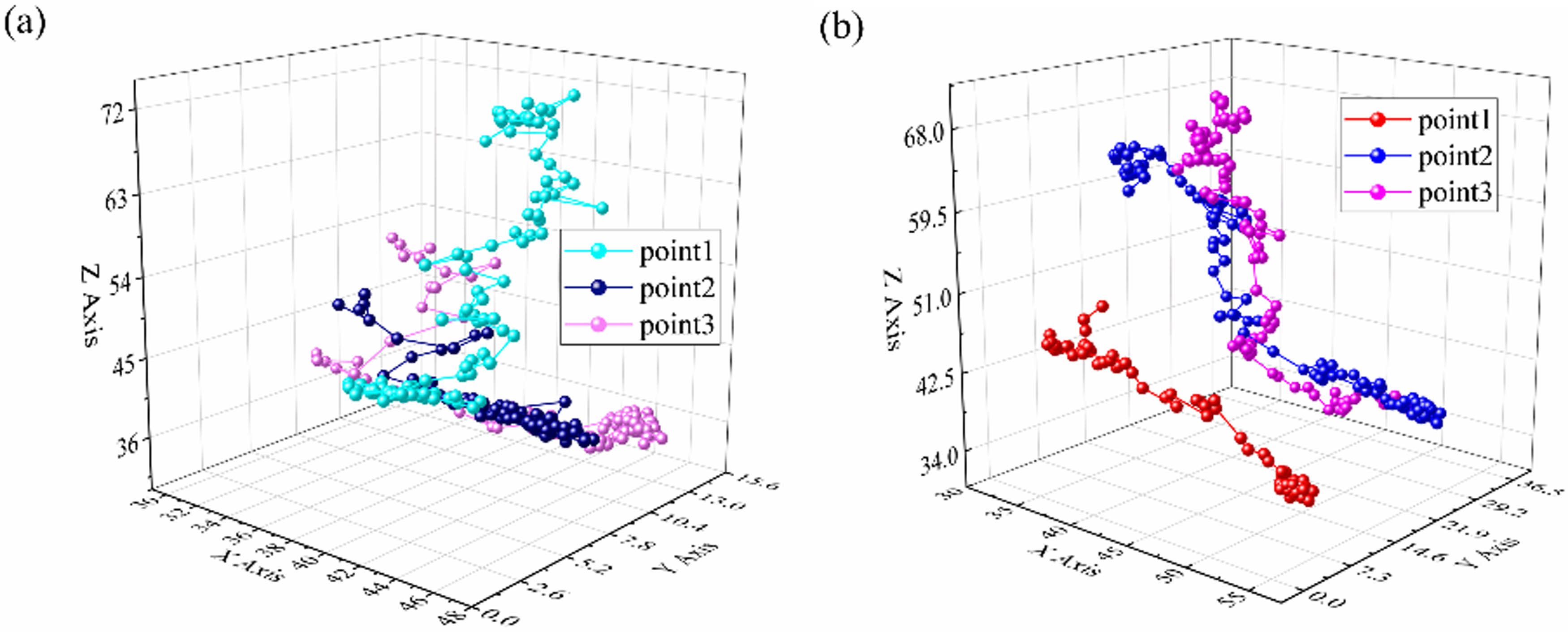
The trajectory of the anchor point: (a) trajectory at vertical injection pressure and (b) trajectory at 45° injection pressure.
In the process of random diffusion of polymer chain from the initial position, deformation and shear behavior exists inside the polymer chain. It is more appropriate to describe its motion state through the mean square displacement (MSD), which is described by the following expression:
where r i (t) and r i (0) denote the coordinates of the atom at time t and initial moment 0.
In the course of nano-injection molding, a large number of atoms directionally migrate under the action of the injection pressure, forming a structural arrangement according to their mass. Figure 6 displays the MSD images of the two sets of experiments, in which the MSD values increase with time. In the early molding stage of molding, the particles of the flexible polymer chain under the action of the external field jumped into the groove space, showing an upward linear trend. The diffusion pattern conformed to Fick’s law of diffusion. Figure 6a depicts the effect of the pressure direction on the MSD. In particular, the influence of the pressure direction on the motion of carbon atoms in the main chain was studied. It was found that the MSD grew slowly at 0–20 ps and then rapidly increased at 20–100 ps. This indicated that the motion in the filling stage before contacting the metal wall was relatively gentle and obeyed Einstein’s law of diffusion. Once affected by the metal frictional resistance and the metal interface structure, the motion became complex and irregular, and the larger the angle of injection pressure, the more intensive the polymer movement. Exhibiting the concave shape from the left groove to the right one, the diffusion was more active, indicating a larger MSD. The MSD at 67.5° is much larger than that at other degrees, and 0° is the smallest, this is because the larger the angle of the injection pressure, the larger the range of motion of the polymer at the same time, and the MSD of 22.5° and 45° is almost the same, which also confirms that there is a flat state of MSD with the increase of the angle of the injection pressure. Figure 6b illustrates the effect of different injection pressures on MSD. MSD increased with increasing injection pressure. After reaching a certain value, the increase of the injection pressure reduced the MSD, and the increase of the positive pressure enhanced the friction between the polymer and the metal wall, which hindered the conformational isomerism of the polymer chains, resulting in a decrease in the MSD. This was also consistent with the previous image analysis. In both figures, the slopes of the curves at the initial stage were almost the same but changed after contact with the metal wall. Because of a variety of processes, the degree of polymer movement and diffusion was also different, resulting in different MSD values.
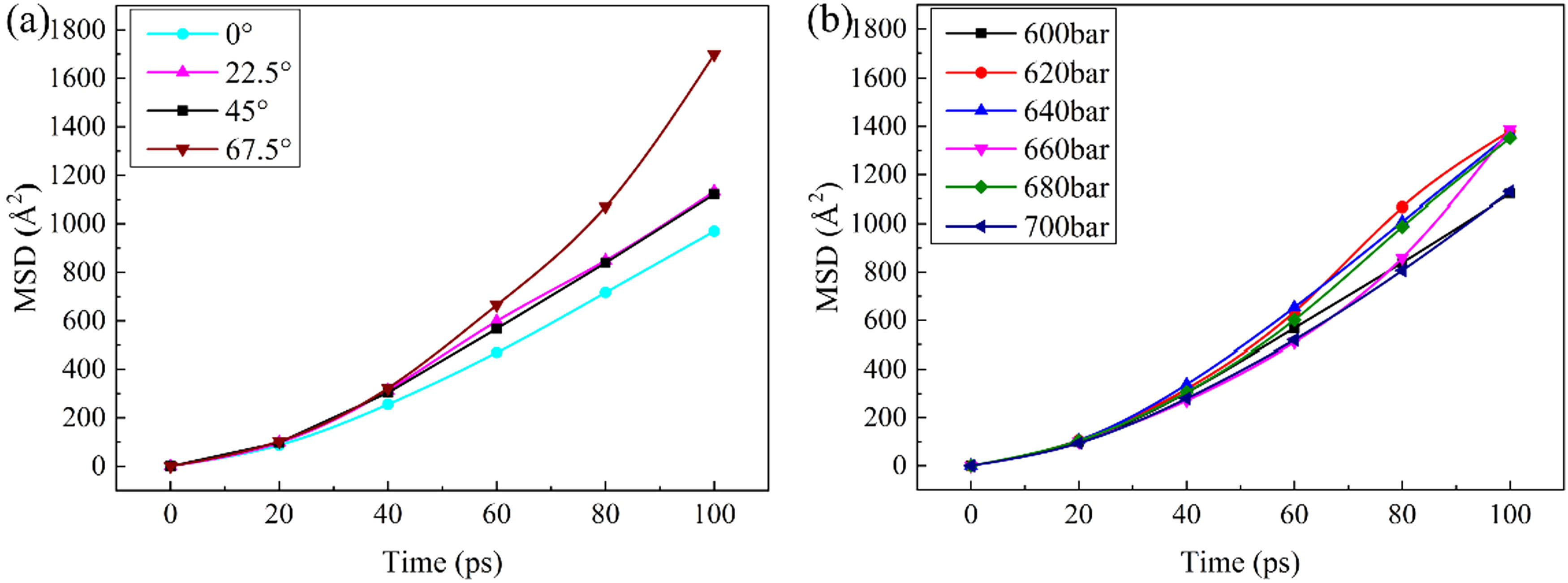
MSD for filling stage of PPS: (a) the influence curve of injection pressure direction on MSD and (b) the influence curve of injection pressure size on MSD.
3.3 Bond strength
The bonding strength of a system mainly depends on the magnitude of the non-binding force at the interface. Molecular dynamics simulation results can be reflected by the strength of the interface energy. The amount of interfacial energy can be expressed as the total system energy minus the energy of the metal and polymer layers. In this study, the interfacial energy was taken as the sum of the bonding and non-bonding energies between the metal and the polymer. Based on Figures 2 and 7a, a zero interfacial energy curve can be divided into three stages. The initial stage covers the first 20 ps when the polymer is not in contact with the metal and the interfacial energy slowly increases. The second stage within 20–75 ps refers to the filling process. At this time, the interface can grow rapidly. Later, due to the limitation of the nano-space and the internal friction of the polymer chain, the interface energy slowly increases. Under the same pressure within 0–80 ps, the polymer chains at 0° has the maximum contact area with the metal interface compared with polymer chians with other angles so the interface energy is greater than other angles, but due to the limitation of the direction of the pressure, the area where the polymer spreads is also limited; as the angle of the pressure increases, the polymer spread has also become larger. At 45°, more polymer has entered the right groove. At 67.5°, under the large horizontal pressure, the polymer almost directly moved to the right groove rather than to the left groove. The value of the interface energy determines the bond strength of the system. In summary, the greater the pressure in the vertical direction, the higher the bond strength between the polymer chains and the metal. The greater the directional pressure, the more active the motion of the polymer, and the greater the spread area. As shown in Figure 7b, as the pressure increased, the interfacial energy of the system also increased. Figure 7c displays the final interfacial energy as a function of pressure. Once it reached 680 bar, the interface energy exhibited a significant downward trend, so the optimal injection pressure was between 620 and 660, consistent with the conclusion of the previous work (28).
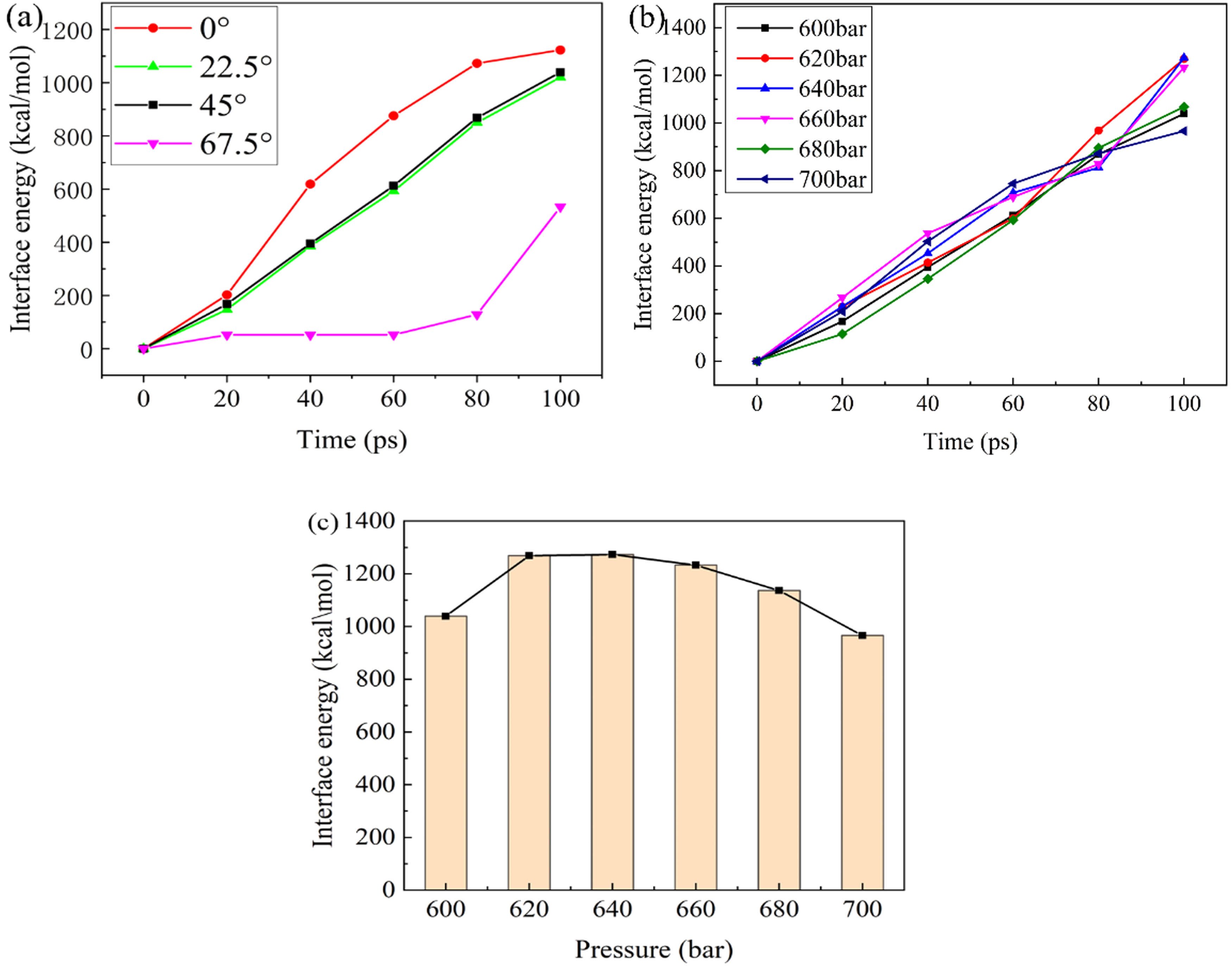
(a and b) Interface energy (kcal‧mol−1)–time (ps) graph and (c) interface energy (kcal‧mol−1)–pressure (bar) graph.
4 Conclusions
Under the condition of three-dimensional periodic boundary, the temperature variation of complex injection molding process was represented by simulating constant temperature field. A PPS/Cu nano-injection interface model with a nanoscale groove structure was established, and the mechanisms of polymer chain injection molding and shear slip were explored by simulating the effects of positive pressure and transverse shear stress. Based on the findings, the main conclusions can be summarized as follow.
The polymer diffusion at the initial stage of nano-injection conforms to Fick’s law. Once the PPS slid along the metal groove wall under the injection pressure, there was apparent obvious internal friction and shear deformation between the polymer chains. When the filling amount reached a certain value, the whole system entered a dynamic equilibrium state.
There are two kinds of adhesion phenomena, one is that the macromolecule slides violently in small areas of some sure nanoscale groove to form multiple anchor points. The other case involves multiple nano-grooves along the metal interface, the polymer chain slides and is bolted as multiple anchors in different grooves due to the exerted wall-drag effect on the neighboring chains. These two slipping and anchoring mechanisms are consistent with de Gennes’ slipping theory.
The contact between the polymer and the metal wall produced many anchoring structures. These anchor points were hardly slipping at a low speed, but jumped at high speed, and the suspended part was bent during the flow process, which was also consistent with de Gennes’ theory.
Studying the bonding between the polymer and metal revealed an optimal injection pressure window. Moreover, as the injection pressure angle increased, the shear flow of the polymer was also more pronounced.
Acknowledgements
The authors thank the anonymous reviewers, whose comments have helped improve the presentation of their work.
-
Funding information: This work was financially supported by the National Natural Science Foundation of China (No. 52165046).
-
Author contributions: Donglei Liu: conceptualization, writing – original draft, writing – review and editing, methodology, formal analysis; Riqing Chen: writing – original draft, investigation, formal analysis, visualization, software; Kai Zhan: investigation, software, data curation; Zizhi Chen: formal analysis; Luo Xin: conceptualization, supervision, project administration, writing – review and editing.
-
Conflict of interest: The authors state no conflict of interest.
-
Data availability statement: The datasets generated during and/or analysed during the current study are available from the corresponding author on reasonable request.
References
(1) Oh JW, Bollina R, Lee WS, Seong JP. Effect of nano powder ratio in bimodal powder mixture on powder injection molding. Powder Technol. 2016;302:168–76.10.1016/j.powtec.2016.08.051Suche in Google Scholar
(2) Barshutina MN, Coulter JP. Application of the sessile-drop method for the quality control of nanostructured polymers for medical use. Russian J Nondestr Test. 2015;51:768–78.10.1134/S1061830915120025Suche in Google Scholar
(3) Feng J, Liao Q, Zhu X, Wu R, Wang H, Ding YD, et al. Molecular dynamics simulation of injection of polyethylene fluid in a variable cross-section nano-channel. Chin Sci Bull. 2011;56:1848–56.10.1007/s11434-010-4317-7Suche in Google Scholar
(4) Lin HY, Chang CH, Young WB. Experimental and analytical study on filling of nano structures in micro injection molding. Int Commun Heat Mass Transf. 2010;37:1477–86.10.1016/j.icheatmasstransfer.2010.08.017Suche in Google Scholar
(5) Daniel J, Panneerselvam K. Mechanical and thermal behaviour of polypropylene/cloisite 30B/elvaloy AC 3427 nanocomposites processed by melt intercalation method. Trans Indian Inst Met. 2017;70:1131–8.10.1007/s12666-016-0908-6Suche in Google Scholar
(6) Gardner DJ, Han Y, Wang L. Wood–plastic composite technology. Curr For Rep. 2015;1:139–50.10.1007/s40725-015-0016-6Suche in Google Scholar
(7) Jung W, Ra J, Park K. Design optimization of ultrasonic horn for micro-pattern replication. Int J Precis Eng Manuf. 2012;13:2195–201.10.1007/s12541-012-0291-0Suche in Google Scholar
(8) Llewelyn G, Rees A, Griffiths CA, Scholz SG. Advances in microcellular injection moulding. J Cell Plast. 2020;56:646–74.10.1177/0021955X20912207Suche in Google Scholar
(9) Piotter V, Gietzelt T, Merz L. Micro powder-injection moulding of metals and ceramics. Sadhana. 2003;28:299–306.10.1007/BF02717139Suche in Google Scholar
(10) Tao HQ, Jane W, Xin Z, Liu YC, Zhe L, Hun JK, et al. Modeling thermal-visco-elastohydrodynamic lubrication (TVEHL) interfaces of polymer-based materials. Tribol Int. 2021;154:106691.10.1016/j.triboint.2020.106691Suche in Google Scholar
(11) Geiger K, Martin GA, Sobotta A. Numerical simulation of flow processes in extrusion tools for partly crosslinked and highly filled plastic melts. Compos Mater. 2019;3:9–21.Suche in Google Scholar
(12) Li YC, Shi RP, Wang CP, Liu XJ, Wang YZ. Phase field study on the effect of shear flow on polymer phase separation. Procedia Eng. 2012;27:1502–7.10.1016/j.proeng.2011.12.614Suche in Google Scholar
(13) Wu XI, Takeshita S, Tadumi K, Wen YD, Shin H, Hiro YN, et al. Preparation of noble metal/polymer nanocomposites via in situ polymerization and metal complex reduction. Mater Chem Phys. 2019;222:300–8.10.1016/j.matchemphys.2018.10.031Suche in Google Scholar
(14) Gao XQ, Xu J, Chen ZC. Improved mechanical properties and structure of PP/nano-CaCO3 blends prepared by low-frequency vibration injection molding. Polym Int. 2008;57:23–7.10.1002/pi.2364Suche in Google Scholar
(15) Surace R, Pagano C, Bellantone V, Gatti S, Castellani L, Vighi M, et al. Injection vs micro-injection molding of nano-particle filled polyamide 6: moldability and structuring. Polymer. 2021;230:124035.10.1016/j.polymer.2021.124035Suche in Google Scholar
(16) Bongiorno A, Pagano C, Baldi F, Vincenzo B, Rossella S, Irene F. Micro-injection molding of CNT nanocomposites obtained via compounding process. Polym Compos. 2017;38:349–62.10.1002/pc.23593Suche in Google Scholar
(17) Foudzi FM, Muhamad N, Sulong AB, Hafizawati Z. Flow behavior characteristic for injection process using nano-yttria stabilized zirconia for micro metal injection molding (µMIM). Appl Mech Mater. 2010;44:480–4.10.4028/www.scientific.net/AMM.44-47.480Suche in Google Scholar
(18) Nishiyabu K, Kakishita K, Tanaka S. Micro metal injection molding using hybrid micro/nano powders. Mater Sci Forum. 2007;49:381–4.10.4028/0-87849-419-7.381Suche in Google Scholar
(19) Zhou MY, Jiang BY, Weng C. Molecular dynamics study on polymer filling into nano-cavity by injection molding. Comput Mater Sci. 2016;120:36–42.10.1016/j.commatsci.2016.04.004Suche in Google Scholar
(20) Zhou MY, Xiong X, Drummer D, Jiang BY. Molecular dynamics simulation and experimental investigation of the geometrical morphology development of injection-molded nanopillars on polymethylmethacrylate surface. Comput Mater Sci. 2018;149:208–16.10.1016/j.commatsci.2018.03.035Suche in Google Scholar
(21) Pranov H, Rasmussen HK, Larsen NB, Nikolaj G. On the injection molding of nanostructured polymer surfaces. Polym Eng Sci. 2010;46:160–71.10.1002/pen.20459Suche in Google Scholar
(22) Masato D, Sorgato M, Batal A, Lucchetta G. Thin-wall injection molding of polypropylene using molds with different laser-induced periodic surface structures. Polym Eng Sci. 2019;59:1889–96.10.1002/pen.25189Suche in Google Scholar
(23) Yang SH, Kwon SY, Lee MY, Cho M. Molecular dynamics and micromechanics study of hygroelastic behavior in graphene oxide-epoxy nanocomposites. Compos Part B. 2019;164:425–36.10.1016/j.compositesb.2019.01.059Suche in Google Scholar
(24) Kadoya S, Kimura F, Yanagishita T, Yusuke K. Structure size effect on polymer infiltration in injection molded direct joining. Precis Eng. 2021;67:100–9.10.1016/j.precisioneng.2020.09.017Suche in Google Scholar
(25) Weng C, Ding T, Zhou MY, Liu JZ, Wang H. Formation mechanism of residual stresses in micro-injection molding of PMMA: a molecular dynamics simulation. Polymers. 2020;12:1368.10.3390/polym12061368Suche in Google Scholar PubMed PubMed Central
(26) Kimura F, Kadoya S, Kajihara Y. Effects of molding conditions on injection molded direct joining using a metal with nano-structured surface. Precis Eng. 2016;45:203–8.10.1016/j.precisioneng.2016.02.013Suche in Google Scholar
(27) Liu DL, Zhou F, Zhou HZ. The polymer–metal interactive behavior in polyphenylene sulfide/aluminium hetero interface in nano injection molding. Compos Interfaces. 2020;27:277–88.10.1080/09276440.2019.1626138Suche in Google Scholar
(28) Li HC, Cai ZM, Zhou F, Liu DL. MD simulation analysis of the anchoring behavior of injection-molded nanopits on polyphenylene sulfide/Cu interface. Compos Interfaces. 2022;29:431–46.10.1080/09276440.2021.1949102Suche in Google Scholar
(29) Liu DL, Zhou F, Li HC, Xin Y, Yi ZW. Study on the interfacial interactions and adhesion behaviors of various polymer–metal interfaces in nano molding. Polym Eng Sci. 2020;61:95–106.10.1002/pen.25558Suche in Google Scholar
(30) Zeng P, Liu DL, Luo X, Zhan K, Yuan T. Influence mechanisms of 2-amino-1,3,5-triazine-4,6-dithiol coating on adhesion properties of polybutylene terephthalate/aluminum interface in nano-injection molding. J Polym Eng. 2022;42:946–56.10.1515/polyeng-2022-0118Suche in Google Scholar
(31) Islam ST, Samanta SK, Das S, Chattopadhyay H. A numerical model to predict the powder–binder separation during micro‐powder injection molding. J Am Ceram Soc. 2022;105(7):4608–20.10.1111/jace.18401Suche in Google Scholar
(32) Sun H, Ren P, Fried J. The COMPASS force field: parameterization and validation for phosphazenes. Comput Theor Polym Sci. 1998;8:229–46.10.1016/S1089-3156(98)00042-7Suche in Google Scholar
(33) Ding H, Karasawa N, Goddard WA. Atomic level simulations on a million particles: the cell multipole method for Coulomb and London nonbond interactions. J Chem Phys. 1992;97:4309–15.10.1063/1.463935Suche in Google Scholar
(34) Essmann U, Perera L, Berkowitz ML, Lee H, Pedersen LG, Perera L. A smooth particle mesh Ewald method. J Chem Phys. 1995;103:8577–93.10.1063/1.470117Suche in Google Scholar
(35) Darden T, York D, Pedersen L. Particle mesh Ewald: an N log(N) method for Ewald sums in large systems. J Chem Phys. 1993;98:10089–92.10.1063/1.464397Suche in Google Scholar
(36) Telles IM, Bombardelli RK, Santos AP, Levin Y. Simulations of electroosmotic flow in charged nanopores using dissipative particle dynamics with Ewald summation. J Mol Liq. 2021;336:116263.10.1016/j.molliq.2021.116263Suche in Google Scholar
(37) Hui W, Yong X. Molecular dynamics simulation of gas diffusion behavior in polyethylene terephthalate/aluminium/polyethylene interface. Compos Interfaces. 2017;24:915–26.10.1080/09276440.2017.1302733Suche in Google Scholar
(38) Zhang JJ, Liu CY, Zhang XL, Zheng LC. An approach on turbulent flow of pseudo-plastic nano-fluids and heat transfer subject to wall slip. Int Commun Heat Mass Transf. 2022;131:105877.10.1016/j.icheatmasstransfer.2021.105877Suche in Google Scholar
(39) Jas GS, Childs EW, Middaugh CR, Kuczera K. Observing reorientation dynamics with time-resolved fluorescence and molecular dynamics in varying periodic boundary conditions. J Biomol Struct Dyn. 2021;40(2):10614–28.10.1080/07391102.2021.1947894Suche in Google Scholar PubMed
(40) Berenika H, Daniel S, Gordana P. Wall-slip of highly filled powder injection molding compounds: effect of flow channel geometry and roughness. AIP Conf Proc. 2015;1599:518.10.1063/1.4876892Suche in Google Scholar
(41) de Geenes PG. Soft interfaces: the 1994 Dirac memorial lecture. New York: Cambridge University Press; 1997. p. 17–41.10.1017/CBO9780511628764Suche in Google Scholar
(42) Rao Q, Xia YD, Li JY, Deo ML, Li Z. Flow reduction of hydrocarbon liquid in silica nanochannel: insight from many-body dissipative particle dynamics simulations. J Mol Liq. 2021;344:117673.10.1016/j.molliq.2021.117673Suche in Google Scholar
© 2023 the author(s), published by De Gruyter
This work is licensed under the Creative Commons Attribution 4.0 International License.
Artikel in diesem Heft
- Research Articles
- Chitosan nanocomposite film incorporating Nigella sativa oil, Azadirachta indica leaves’ extract, and silver nanoparticles
- Effect of Zr-doped CaCu3Ti3.95Zr0.05O12 ceramic on the microstructure, dielectric properties, and electric field distribution of the LDPE composites
- Effects of dry heating, acetylation, and acid pre-treatments on modification of potato starch with octenyl succinic anhydride (OSA)
- Loading conditions impact on the compression fatigue behavior of filled styrene butadiene rubber
- Characterization and compatibility of bio-based PA56/PET
- Study on the aging of three typical rubber materials under high- and low-temperature cyclic environment
- Numerical simulation and experimental research of electrospun polyacrylonitrile Taylor cone based on multiphysics coupling
- Experimental investigation of properties and aging behavior of pineapple and sisal leaf hybrid fiber-reinforced polymer composites
- Influence of temperature distribution on the foaming quality of foamed polypropylene composites
- Enzyme-catalyzed synthesis of 4-methylcatechol oligomer and preliminary evaluations as stabilizing agent in polypropylene
- Molecular dynamics simulation of the effect of the thermal and mechanical properties of addition liquid silicone rubber modified by carbon nanotubes with different radii
- Incorporation of poly(3-acrylamidopropyl trimethylammonium chloride-co-acrylic acid) branches for good sizing properties and easy desizing from sized cotton warps
- Effect of matrix composition on properties of polyamide 66/polyamide 6I-6T composites with high content of continuous glass fiber for optimizing surface performance
- Preparation and properties of epoxy-modified thermosetting phenolic fiber
- Thermal decomposition reaction kinetics and storage life prediction of polyacrylate pressure-sensitive adhesive
- Effect of different proportions of CNTs/Fe3O4 hybrid filler on the morphological, electrical and electromagnetic interference shielding properties of poly(lactic acid) nanocomposites
- Doping silver nanoparticles into reverse osmosis membranes for antibacterial properties
- Melt-blended PLA/curcumin-cross-linked polyurethane film for enhanced UV-shielding ability
- The affinity of bentonite and WO3 nanoparticles toward epoxy resin polymer for radiation shielding
- Prolonged action fertilizer encapsulated by CMC/humic acid
- Preparation and experimental estimation of radiation shielding properties of novel epoxy reinforced with Sb2O3 and PbO
- Fabrication of polylactic acid nanofibrous yarns for piezoelectric fabrics
- Copper phenyl phosphonate for epoxy resin and cyanate ester copolymer with improved flame retardancy and thermal properties
- Synergistic effect of thermal oxygen and UV aging on natural rubber
- Effect of zinc oxide suspension on the overall filler content of the PLA/ZnO composites and cPLA/ZnO composites
- The role of natural hybrid nanobentonite/nanocellulose in enhancing the water resistance properties of the biodegradable thermoplastic starch
- Performance optimization of geopolymer mortar blending in nano-SiO2 and PVA fiber based on set pair analysis
- Preparation of (La + Nb)-co-doped TiO2 and its polyvinylidene difluoride composites with high dielectric constants
- Effect of matrix composition on the performance of calcium carbonate filled poly(lactic acid)/poly(butylene adipate-co-terephthalate) composites
- Low-temperature self-healing polyurethane adhesives via dual synergetic crosslinking strategy
- Leucaena leucocephala oil-based poly malate-amide nanocomposite coating material for anticorrosive applications
- Preparation and properties of modified ammonium polyphosphate synergistic with tris(2-hydroxyethyl) isocynurate for flame-retardant LDPE
- Thermal response of double network hydrogels with varied composition
- The effect of coated calcium carbonate using stearic acid on the recovered carbon black masterbatch in low-density polyethylene composites
- Investigation of MXene-modified agar/polyurethane hydrogel elastomeric repair materials with tunable water absorption
- Damping performance analysis of carbon black/lead magnesium niobite/epoxy resin composites
- Molecular dynamics simulations of dihydroxylammonium 5,5′-bistetrazole-1,1′-diolate (TKX-50) and TKX-50-based PBXs with four energetic binders
- Preparation and characterization of sisal fibre reinforced sodium alginate gum composites for non-structural engineering applications
- Study on by-products synthesis of powder coating polyester resin catalyzed by organotin
- Ab initio molecular dynamics of insulating paper: Mechanism of insulating paper cellobiose cracking at transient high temperature
- Effect of different tin neodecanoate and calcium–zinc heat stabilizers on the thermal stability of PVC
- High-strength polyvinyl alcohol-based hydrogel by vermiculite and lignocellulosic nanofibrils for electronic sensing
- Impacts of micro-size PbO on the gamma-ray shielding performance of polyepoxide resin
- Influence of the molecular structure of phenylamine antioxidants on anti-migration and anti-aging behavior of high-performance nitrile rubber composites
- Fiber-reinforced polyvinyl alcohol hydrogel via in situ fiber formation
- Preparation and performance of homogenous braids-reinforced poly (p-phenylene terephthamide) hollow fiber membranes
- Synthesis of cadmium(ii) ion-imprinted composite membrane with a pyridine functional monomer and characterization of its adsorption performance
- Impact of WO3 and BaO nanoparticles on the radiation shielding characteristics of polydimethylsiloxane composites
- Comprehensive study of the radiation shielding feature of polyester polymers impregnated with iron filings
- Preparation and characterization of polymeric cross-linked hydrogel patch for topical delivery of gentamicin
- Mechanical properties of rCB-pigment masterbatch in rLDPE: The effect of processing aids and water absorption test
- Pineapple fruit residue-based nanofibre composites: Preparation and characterizations
- Effect of natural Indocalamus leaf addition on the mechanical properties of epoxy and epoxy-carbon fiber composites
- Utilization of biosilica for energy-saving tire compounds: Enhancing performance and efficiency
- Effect of capillary arrays on the profile of multi-layer micro-capillary films
- A numerical study on thermal bonding with preheating technique for polypropylene microfluidic device
- Development of modified h-BN/UPE resin for insulation varnish applications
- High strength, anti-static, thermal conductive glass fiber/epoxy composites for medical devices: A strategy of modifying fibers with functionalized carbon nanotubes
- Effects of mechanical recycling on the properties of glass fiber–reinforced polyamide 66 composites in automotive components
- Bentonite/hydroxyethylcellulose as eco-dielectrics with potential utilization in energy storage
- Study on wall-slipping mechanism of nano-injection polymer under the constant temperature fields
- Synthesis of low-VOC unsaturated polyester coatings for electrical insulation
- Enhanced apoptotic activity of Pluronic F127 polymer-encapsulated chlorogenic acid nanoparticles through the PI3K/Akt/mTOR signaling pathway in liver cancer cells and in vivo toxicity studies in zebrafish
- Preparation and performance of silicone-modified 3D printing photosensitive materials
- A novel fabrication method of slippery lubricant-infused porous surface by thiol-ene click chemistry reaction for anti-fouling and anti-corrosion applications
- Development of polymeric IPN hydrogels by free radical polymerization technique for extended release of letrozole: Characterization and toxicity evaluation
- Tribological characterization of sponge gourd outer skin fiber-reinforced epoxy composite with Tamarindus indica seed filler addition using the Box–Behnken method
- Stereocomplex PLLA–PBAT copolymer and its composites with multi-walled carbon nanotubes for electrostatic dissipative application
- Enhancing the therapeutic efficacy of Krestin–chitosan nanocomplex for cancer medication via activation of the mitochondrial intrinsic pathway
- Variation in tungsten(vi) oxide particle size for enhancing the radiation shielding ability of silicone rubber composites
- Damage accumulation and failure mechanism of glass/epoxy composite laminates subjected to repeated low velocity impacts
- Gamma-ray shielding analysis using the experimental measurements for copper(ii) sulfate-doped polyepoxide resins
- Numerical simulation into influence of airflow channel quantities on melt-blowing airflow field in processing of polymer fiber
- Cellulose acetate oleate-reinforced poly(butylene adipate-co-terephthalate) composite materials
- Radiation shielding capability and exposure buildup factor of cerium(iv) oxide-reinforced polyester resins
- Recyclable polytriazole resins with high performance based on Diels-Alder dynamic covalent crosslinking
- Adsorption and recovery of Cr(vi) from wastewater by Chitosan–Urushiol composite nanofiber membrane
- Comprehensive performance evaluation based on electromagnetic shielding properties of the weft-knitted fabrics made by stainless steel/cotton blended yarn
- Review Articles
- Preparation and application of natural protein polymer-based Pickering emulsions
- Wood-derived high-performance cellulose structural materials
- Flammability properties of polymers and polymer composites combined with ionic liquids
- Polymer-based nanocarriers for biomedical and environmental applications
- A review on semi-crystalline polymer bead foams from stirring autoclave: Processing and properties
- Rapid Communication
- Preparation and characterization of magnetic microgels with linear thermosensitivity over a wide temperature range
- Special Issue: Biodegradable and bio-based polymers: Green approaches (Guest Editors: Kumaran Subramanian, A. Wilson Santhosh Kumar, and Venkatajothi Ramarao)
- Synthesis and characterization of proton-conducting membranes based on bacterial cellulose and human nail keratin
- Fatigue behaviour of Kevlar/carbon/basalt fibre-reinforced SiC nanofiller particulate hybrid epoxy composite
- Effect of citric acid on thermal, phase morphological, and mechanical properties of poly(l-lactide)-b-poly(ethylene glycol)-b-poly(l-lactide)/thermoplastic starch blends
- Dose-dependent cytotoxicity against lung cancer cells via green synthesized ZnFe2O4/cellulose nanocomposites