Damage accumulation and failure mechanism of glass/epoxy composite laminates subjected to repeated low velocity impacts
-
Hao Li
 ,
Zhaogang Yu
,
Zhaogang Yu

Abstract
In this work, the damage accumulation and failure mechanism of glass fiber-reinforced epoxy composite laminates under repeated low velocity impacts were studied considering the influence of stacking sequence. The typical sandwich-like [0°2/90°2]s, angle-ply [±45°]2s and quasi-isotropic [0°/−45°/45°/90°]s laminates were tested at 20 J impact energy. The impact responses including contact force–time/central displacement and energy–time curves were recorded. The tendencies of the peak contact force, maximum displacement, bending stiffness, and energy dissipation with the increase in impact number were analyzed. Damage induced in the laminates was further evaluated. The results show that the impact resistance of the sandwich-like laminate is the weakest with the lowest peak load and the highest energy dissipation. The impact resistance of the quasi-isotropic laminate is better relative to the angle-ply laminate before the occurrence of fiber breakage, whereas the damage tolerance of the angle-ply laminate is higher with relatively slower damage accumulation at subsequent impacts.
1 Introduction
Fiber-reinforced composites are the most prominent materials nowadays attributed to their lightweight, significant strength, high stiffness, and convenient for industrial manufacture. They have been widely employed in aerospace, automotive, marine, and other fields (1,2,3,4). However, composites are sensitive to transverse loading such as low velocity impact load owing to their out-of-plane low load bearing capacity. In past decades, numerous investigations have been carried out on the low velocity impact responses and damage development of composite laminates (5,6,7,8,9). Typical damage modes such as matrix cracking and fiber breaking induced in intralaminar, and delamination caused at interlaminar are revealed during single low velocity impact process, which is the well-known barely visible impact damage that weakens the mechanical performance of the composite laminates. In most realistic cases, composite laminates are more likely to encounter repeated impacts than a single localized impact during the process of production, daily maintenance, and service life (10,11). Although only small damage is generated in each single impact, these defects can easily accumulate under repeated impacts, leading to severe damage and cause major mechanical properties degradation (12). Therefore, the necessity to investigate fiber-reinforced composites subjected to repeated impacts becomes apparent.
Abundance of research works on the repeated impact dynamic behaviors and damage mechanism of polymer composites have been carried out over the past decades. Many scholars have focused on the effects of impact angle (13) and energy (14,15), impactor shapes (16) and diameter (17), and external environmental conditions such as thermal aging (18) and low temperature (19) on the dynamic responses and damage accumulation of polymer composites subjected to repeated low velocity impacts. Dogan (16) investigated the influences of impactor shapes on the repeated impact responses of the thermoplastic and thermoset matrix-based composite panels. Compared with the shape of hemisphere, the repeated impact number achieving penetration decreased dramatically in conical impact cases. The influence of impactor diameter on the repeated low velocity impact response and damage accumulation mechanism of composite laminates was investigated by Liao et al. (17). A new damage evaluation index DI-B was proposed based on bending stiffness reduction rate and normalized maximum displacement, which could characterize the damage accumulation of fiber-reinforced composite laminates and distinguish the appearance of perforation well. The repeated low velocity impact testing was also performed to reveal the impact mechanical responses of repaired polymer composites (20,21), fiber metal laminates (22,23), and sandwich structures (24,25). Both experimental and numerical methods were adopted by Sun et al. (21) to determine the damage evolution and energy dissipation of patch-repaired composite laminates under repeated impacts. Their work indicated that the delamination damage closely reflected the damage accumulation degree of patch-repaired composites subjected to repeated impacts. In addition, many investigations have been conducted on the repeated impact responses and damage mechanism of the composite laminates with different material types (26,27), ply stacking sequences (28,29), and thicknesses (30,31). The repeated low velocity impact dynamic responses of the hybrid plain-woven graphite and glass fiber-reinforced composite laminates with two sandwich lay-up configurations (28) and the balanced carbon fiber-reinforced laminates (symmetric, asymmetric, and antisymmetric) (29) have been explored. However, there are few reports on the influence of stacking sequence on the impact behavior of glass fiber-reinforced composite laminates subjected to repeated low velocity impacts. The stacking pattern is crucial for the impact resistance and damage accumulation of composite laminates under successive impacts, needing more attention and exploration.
In this study, the repeated low velocity impact dynamic responses and damage accumulation of unidirectional glass fiber-reinforced composite laminates with three representative lay-up structures were studied. First, the repeated impact testing was conducted until the occurrence of the perforation. The impact mechanical behaviors such as the impact contact force, central displacement and energy vs time curves were recorded. The variations in the mechanical responses including peak impact force, maximum central displacement, bending stiffness, and energy dissipation were analyzed. Then, the external and internal damage was identified using the nondestructive and destructive methods containing visual inspection, stereo microscope, ultrasonic C-scan technique, and scanning electron microscope (SEM). The impact resistance and damage evolution of the three stacking configurations were determined. Finally, the damage accumulation of the studied composite laminates was evaluated employing two typical damage variables, and the influence of stacking sequences on the damage accumulation was analyzed.
2 Experimental procedure
2.1 Specimen preparation
In this study, the unidirectional glass fiber and vinyl ester resin were employed as the reinforced fiber and matrix material for the composite laminates, respectively. Added with the hardening agent of methyl ethyl ketone peroxide and the accelerating agent of dimethylaniline, the resin can be well cured at room temperature. The weight ratio of the resin, hardening agent, and accelerating agent was specified as 100:1:0.2. The surface density of the unidirectional glass fiber cloth with one layer thickness of 0.25 mm was 450 g·m−2. And the tensile mechanical properties of the glass fiber cloth were 72 GPa in modulus and 1.57 GPa in strength, respectively. All the experimental materials mentioned above were purchased from Tongxiang Mengtai Reinforced Composite Material Company (Tongxiang, China).
The composite laminates were manufactured by the VARI technology which was usually applied to the thermosetting composites. The schematic diagram of the VARI process is displayed in Figure 1. The preparation of the original composite plates was completed on the smooth and clean glass plate placed on a table. One layer release cloth, glass fiber clothes, one layer release cloth, and the diversion net were arranged on the work bench from the bottom to top. The preparation laminates can be easily separated from the work bench with the help of release clothes on each side. Guided by the diversion net, the fiber clothes can be saturated with resin uniformly. The whole system was covered by a vacuum bag and was in vacuum environment after the work of vacuum pump. After the injection of resin, the system was cured for 24 h at the vacuum level of 650 mbar. The original laminates with three stacking sequences of [0°2/90°2]s, [±45°]2s, and [0°/−45°/45°/90°]s were fabricated. The specimens with the dimension of 150 mm × 100 mm × 2.8 mm were cut from the original laminates using a diamond saw blade cutting machine.

Specimen preparation: (a) vacuum-assisted resin injection (VARI) process and (b) the studied stacking sequences.
2.2 Repeated low velocity impact testing
According to the ASTM D7136 standard, repeated low velocity impact testing was performed using the Instron Dynatup CEAST 9340 machine at room temperature, as presented in Figure 2. The test platform was mainly composed of the specimen fixture, a drop hammer device, and a data acquisition system. During the impact event, composite specimens were firmly fastened between two steel plates with 76 mm diameter hole at the center. Controlled by the control platform, the impactor fell from the specified impact height. Then, the impactor struck the center of the specimen and bounced up after the process of contact. Finally, the impactor was caught by the anti-secondary impact device avoiding the second impact. Above the projectile head, a piezo-electric load cell as the dynamic force sensor was used to measure the impact contact force. The contact force data were collected by the data acquisition system in real time, which was employed to calculate the impact kinetic energy of the impactor combining the initial impact velocity at the moment of impact occurrence. The hemispherical impactor with 16 mm diameter and 8 kg weight was raised to the initial given height to implement low velocity impacts. The impact energy level was set as 20 J, corresponding to the initial impact velocity of 2.236 m·s−1 in this work. The repeated low velocity impact tests were realized by raising the impactor to the initial given height after previous impact. To guarantee the reliability of the testing, five specimens were struck for each stacking sequence. To evaluate the induced damage, the external damage morphology on both surfaces was observed by visual inspection, the extent of the internal damage was detected applying the stereo microscope and ultrasonic C-scan technique, and the micro-damage morphology of the central damage region was determined by means of the SEM.

Setup of the low velocity impact testing: (a) drop weight impact testing machine, (b) anti-secondary impact device, and (c) fixed specimen.
3 Results and discussion
3.1 Repeated impact dynamic mechanical responses
The impact contact force–time/displacement curves of the specimens with the stacking sequences of [0°2/90°2]s, [±45°]2s, and [0°/−45°/45°/90°]s under repeated low velocity impacts are plotted in Figure 3. The specimens experience similar impact response trend regardless of the stacking sequence during the impact test, starting with the typical rebounding curve at low impact number, followed by the penetration feature with the impactor gradually embedding into the specimen, until the occurrence of the perforation representing the failure of the specimen. For each lay-up configuration, the impact contact peak force first increases and then decreases with the increase in impact number, and the maximum central displacement of the specimen increases with the rise in impact number until the perforation.
![Figure 3
Repeated impact responses (contact force vs time and force–displacement curves) and the corresponding damage morphology detected by stereo microscope: (a) specimens with the lay-up sequence of [0°2/90°2]s, (b) specimens with the ply orientation of [±45°]2s, (c) specimens with the stacking sequence of [0°/−45°/45°/90°]s, and (d) damage morphology at the four stages.](/document/doi/10.1515/epoly-2023-0146/asset/graphic/j_epoly-2023-0146_fig_003.jpg)
Repeated impact responses (contact force vs time and force–displacement curves) and the corresponding damage morphology detected by stereo microscope: (a) specimens with the lay-up sequence of [0°2/90°2]s, (b) specimens with the ply orientation of [±45°]2s, (c) specimens with the stacking sequence of [0°/−45°/45°/90°]s, and (d) damage morphology at the four stages.
As shown in Figure 3(a–c), each of the stacking configurations exhibits four typical characteristics of the force–time and force–displacement curves during the repeated impact tests, namely, the initial local fluctuation in the ascending stage of the first impact, a drop of the impact force before reaching the peak force, large drop of the impact force, and almost constant plateau of the impact force. The four typical features of impact responses are closely related to the damage induced in the specimen. With the help of stereo microscope, the transverse damage morphology corresponding the four stages was detected and displayed in Figure 3(d). It is observed that the initial local fluctuation in the rising phase of the first impact is mainly caused by the unstable damage propagation of matrix cracking and the initiation of delamination. The damage mode of matrix cracking is clearly observed through the thickness of the specimens with all stacking sequences. Similar phenomenon also appeared in the works of Sun et al. (21) and Rezasefat et al. (32). It is the first time the impact force has a drop before reaching the peak value at the second impact for the specimens with the stacking sequences of [±45°]2s and [0°/−45°/45°/90°]s, and at the third impact for the specimen with the lay-up sequence of [0°2/90°2]s. As indicated in literature (17,33), this impact characteristic can be regarded as the known delamination threshold, describing a distinguishable drop of the impact force in the ascending stage. The distinct delamination presented by the damage morphology in the cross-section of the specimens demonstrates this phenomenon. The contact force has an obvious drop just reaching the peak value at the 5th, 11th, and 7th impact for the specimens with the stacking sequences of [0°2/90°2]s, [±45°]2s, and [0°/−45°/45°/90°]s, respectively. The sharp force drop can be explained by the appearance of fiber breakage, which can be demonstrated by the transverse damage morphology at the region beneath the impactor acquired by the stereo microscope technique. This is consistent with the phenomenon found in previous research works (28,31). The impact force becomes approximately constant value at the 16th, 19th, and 14th impact for the specimens with the lay-up sequences of [0°2/90°2]s, [±45°]2s, and [0°/−45°/45°/90°]s, respectively. As reported in previous studies (34,35), the appearance of constant force plateau reveals the occurrence of perforation of the specimen. The contact force is produced resulting from the friction between the impactor and the laminate during the insertion process, thus the impact force keeps a roughly stable value. Indeed, large amounts of fiber breakage through the thickness is observed in a cross-section view.
The representative energy–time curves of the three laminated specimens during repeated impact testing are illustrated in Figure 4. During an impact event, the impact energy is partly converted into the elastic energy of the laminate, and the other is absorbed by the laminate through plastic deformation, friction, and various failure processes (36). The elastic energy reserved in the laminate is released to rebound the impactor after the contact between the impactor and laminate. Due to the low strain to failure of the glass fiber and the brittle nature of the epoxy resin matrix, the composite laminates show very little or no plastic deformation. Therefore, the absorbed impact energy is mainly dissipated by the damage induced in the laminates, such as matrix cracking, delamination, and fiber breakage. It can be seen that large part of the impact energy is absorbed by the damage for the impact events including the rebounding stage, while relatively less elastic energy is transformed into the kinetic energy of the impactor in the rebounding stage. The absorbed energy first has a little decrease in initial few impact tests and then increases with the rise in the impact number. Moreover, the absorbed energy has an evident increase at the impact number of the appearance of fiber breakage regardless of the stacking sequence. For the perforation event, the impact energy is completely absorbed by the specimens, i.e., the energy absorption reaches the initial impact kinetic energy of the impactor, which is coincided with the indication in the literature (34,37). Hence, the perforation occurs at the 16th, 19th, and 14th impact for the specimens with the stacking sequences of [0°2/90°2]s, [±45°]2s, and [0°/−45°/45°/90°]s, respectively.
![Figure 4
Typical energy vs time curves during repeated impact tests: (a) the schematic diagram of the energy–time curve, (b) the [0°2/90°2]s laminated specimens, (c) the [±45°]2s laminated specimens, and (d) the [0°/−45°/45°/90°]s laminated specimens.](/document/doi/10.1515/epoly-2023-0146/asset/graphic/j_epoly-2023-0146_fig_004.jpg)
Typical energy vs time curves during repeated impact tests: (a) the schematic diagram of the energy–time curve, (b) the [0°2/90°2]s laminated specimens, (c) the [±45°]2s laminated specimens, and (d) the [0°/−45°/45°/90°]s laminated specimens.
3.2 Analysis of the impact mechanical responses
The variations in impact mechanical responses including the peak force, maximum central displacement, absorbed energy, and bending stiffness for the three lay-up specimens under repeated impacts until perforation are plotted in Figure 5. In general, as shown in Figure 5(a), the peak force of the three stacking specimens first increases in the initial few impacts, and then roughly keeps constant plateau, followed by a gradual decrease until the occurrence of perforation. As indicated in works (32,38), the increase in the peak force for the initial few impacts can be attributed to the compaction effect of the laminate. After the first impact, the intact fibers bear the impact loading instead of the damaged matrix beneath the impact location, which results in a local stiffer contact between the impactor and the enhanced phase at the central region for successive few impacts. Thus, the peak force acquires a higher value. With the stable development of matrix cracking and delamination, the impact contact loading is primarily undertaken by the intact fibers, leading to the constant plateau of the peak force. The peak force has a significant drop at the 5th, 11th, and 7th impact for the specimens with the stacking sequences of [0°2/90°2]s, [±45°]2s, and [0°/−45°/45°/90°]s, respectively. This phenomenon results from the appearance of severe damage mode of fiber breakage. Subsequently, the peak force gradually decreases with the intensity of fiber breakage. At the impact of perforation, the peak force drops disastrously due to the loss of load bearing capacity of the specimens. On the whole, the peak force of the angle-ply [±45°]2s and quasi-isotropic [0°/−45°/45°/90°]s specimens is always higher than that of the sandwich-like [0°2/90°2]s specimen at the same impact number, which suggests that the former specimens possess a relatively higher load bearing capability. Hence, the impact resistance of the angle-ply and quasi-isotropic specimens is better than the sandwich-like specimen. Compared to the quasi-isotropic specimen, the peak force of the angle-ply specimen is little lower at initial few impact numbers caused by the lower impact bending stiffness, which is consistent with the results recorded in literature (39,40). However, the peak force of the quasi-isotropic specimen drops quickly after the impact number of the 7th corresponding occurrence of fiber breakage, which indicates the damage of this specimen induced by the fiber breakage develops much more fastly. This phenomenon is also caused by the large continuous delamination propagation illustrated below, which severely reduces the integrity of the specimen and degrades the load carrying capacity. As a consequence, the peak force of the quasi-isotropic specimen is lower than that of the angle-ply specimen in subsequent impacts, which demonstrates that the angle-ply laminate acquires better impact resistance under repeated low velocity impacts.

Changes in the impact characteristics with respect to the impact number: (a) peak force, (b) maximum displacement, (c) bending stiffness, and (d) absorbed energy.
The variation in maximum central displacement with respect to the impact number is displayed in Figure 5(b). The maximum central displacement first increases very slowly before the 5th, 11th, and 7th impact for the specimens with the stacking sequences of [0°2/90°2]s, [±45°]2s, and [0°/−45°/45°/90°]s, respectively. Then, it has an evident increase because of the sudden drop in impact bending stiffness arisen from fiber breakage. Subsequently, the maximum displacement gradually increases with the impact number rising before the penetration. At last, the maximum displacement has a dramatic increase due to the severe damage induced in the specimens. In addition, the rate of increase for the maximum displacement of the quasi-isotropic specimen is obviously larger than that of the sandwich-like and angle-ply specimens after the occurrence of fiber breakage, which indicates that the damage accumulation of this laminate is relatively faster. The gradually intensified fiber breakage and continuous delamination propagation interact with each other, resulting in the faster increase of the maximum central displacement of the quasi-isotropic specimen. On the whole, the maximum central displacement of the angle-ply specimen is the lowest among the three lay-up configurations at the same impact number, and the maximum displacement at the perforation event is also the lowest compared to the other two specimens. Meanwhile, the rate of increase for the maximum displacement of angle-ply specimen is relatively slow and stable throughout the repeated impacts. It thus can be concluded that the impact resistance of the angle-ply laminate is better subjected to repeated low velocity impacts.
The impact bending stiffness of the three laminated structures, obtained by the slope of the ascending phase in the force–displacement curves, is illustrated in Figure 5(c). As indicated in previous studies (17,32), the impact bending stiffness is closely associated with the damage evolution of the impacted laminates. It is evident that the bending stiffness first declines slowly for all prepared specimens, which is due to the gradual development of matrix cracking and delamination induced in the specimens. As revealed by Liao et al. (17), the reduction in impact bending stiffness of laminates is directly related to the propagation of delamination damage before the appearance of fiber breakage. Then, the bending stiffness shows a significant drop at the 6th, 12th, and 8th impact, resulted from the impact-induced fiber breakage at the 5th, 11th, and 7th impact for the specimens with the ply orientations of [0°2/90°2]s, [±45°]2s, and [0°/−45°/45°/90°]s, respectively. Finally, the bending stiffness continuously decreases as the impact-induced damage gradually intensifies at subsequent impacts until perforation.
In general, the bending stiffness of the angle-ply and quasi-isotropic specimens is always larger than that of the sandwich-like specimen at the same impact number, which indicates that the former two lay-up configurations can reserve the mechanical performance relatively better and less damage is induced in the laminates during the repeated impacts. It can also be seen that the bending stiffness of the quasi-isotropic specimen is a little higher than that of the angle-ply specimen before the appearance of fiber breakage, while it decreases sharply with the gradual accumulation of fiber breakage and is even lower than that of the angle-ply specimen in subsequent impacts. As shown in the following part, the continuous propagation of delamination damage also contributes to the degradation of the bending stiffness of the quasi-isotropic specimen. Therefore, the angle-ply laminate possesses the most superior impact resistance and damage tolerance among the three prepared laminates subjected to repeated impacts.
The change in absorbed energy relative to the impact number for the three kinds of specimens is shown in Figure 5(d). It is clear that the absorbed energy gradually decreases at first few impacts for all the prepared specimens. As analyzed above, the matrix cracking and delamination are the dominant damage modes during the initial few impacts. As indicated in previous studies (21,32), the first hit causes the major damage to the laminates when the damage induced in the central region of the laminate is primarily characterized by the matrix cracking and delamination. Due to the compaction effect, the intact fibers support more impact loading relative to the damaged matrix, and the propagation of delamination is more or less restrained. Then, the absorbed energy gradually increases with the increase in the impact number, and an obvious increase in the absorbed energy is observed at the impact number of the appearance of fiber breakage. Finally, the absorbed energy almost reaches the initial impact energy at the 16th, 19th, and 14th impact for the first time, respectively. This means the occurrence of the perforation. In general, the absorbed energy of the sandwich-like specimen is larger than that of the angle-ply and quasi-isotropic specimens at the same impact number, which indicates that more damage is caused in the specimen and the impact resistance is weaker. The absorbed energy of quasi-isotropic specimen is lower than that of angle-ply specimen before the occurrence of fiber breakage at the same impact number, which demonstrates that the impact performance of quasi-isotropic laminate is more superior when the damage induced in laminates is dominated by the matrix cracking and delamination. Compared to the angle-ply specimen, the larger peak force and impact bending stiffness also prove the better impact resistance of the quasi-isotropic specimen for first few impacts. However, compared with the quasi-isotropic specimen, lower absorbed energy of the angle-ply specimen is clearly observed at each impact event in subsequent impacts, and the total energy dissipation is relatively higher owing to the more impact numbers until perforation. This indicates that less damage is induced at each strike in subsequent impact events and the damage tolerance is higher for the angle-ply laminate.
3.3 Damage morphology and damage evolution
The damage evolution of fiber-reinforced composite laminates under repeated low velocity impacts is extremely complex due to the damage accumulation effect. To a certain extent, the damage evolution of the impacted laminates can be revealed by the damage morphology recorded in each impact event. To acquire a clear observation on the damage morphology on both surfaces of the specimens, the central region with 100 mm × 60 mm in dimension is chosen as the damage is mainly induced surrounding the impact point.
The representative damage morphology on both surfaces of the three stacking specimens at the four stages is illustrated in Figure 6(a). A small quantity of matrix cracking on the front surface and delamination on the rear surface is observed for all the prepared specimens at stage I dominated by the matrix cracking damage. For the stage II of the delamination threshold, the matrix cracking on the front surface has a little propagation, while the delamination on the rear surface has an obvious development. After full expansion of matrix cracking and delamination beneath the impact position, the damage of fiber breakage is induced at stage III. It can be seen that a circular indention is left on the front surface, and large delamination with an evident hump is observed on the rear surface. The impactor has inserted into the specimens and abundant fiber breakage occurs at the central region of the specimens at stage IV of perforation. And the pit depths of 2.65, 2.37, and 2.22 mm are left in the composite laminates with the stacking sequences of [0°2/90°2]s, [±45°]2s, and [0°/−45°/45°/90°]s, respectively. On the whole, the damage induced in the laminates becomes more severe with the increase in the impact number. By comparison, the matrix cracking in the front view propagates along the ply directions, namely, the 0°/90° direction for the specimen with the stacking sequence of [0°2/90°2]s and the +45°/−45° direction for the specimens with the lay-up sequence of [±45°]2s, and the delamination in the rear view develops in an elliptical shape with the major axis along the stacking direction of the outermost layer, namely, the 0° direction for the sandwich-like specimen and the +45° direction for the angle-ply specimen. While, for the specimen with the ply orientation of [0°/−45°/45°/90°]s, the matrix cracking on the front side propagates in all orientations, and the delamination on the back side extends approximately in a circular form. To make a more clear observation on the damage region caused in the composite laminates, the ultrasonic C-scan technology has been widely applied to determine the total projected delamination area. The delamination areas of the three stacking specimens with the selected central region of 100 mm × 60 mm in dimension at the four stages are also shown in Figure 6(b). The change in the delamination region and the delamination propagation are revealed more clearly by the C-scan images, which are consistent with the damage morphology discussed above. As reported in previous studies (41,42), the matrix cracking occurs parallel to the fibers first due to the debonding between the fiber and the matrix. Then, the delamination is triggered in the matrix-rich region when matrix cracking propagates to the interface between two adjacent plies with different orientations. And the delamination develops along the orientation of the bottom ply. Subsequently, after extreme development of matrix cracking and delamination, the fiber breakage is caused by the local high stress and the indentation influences of shear pressures. Finally, the laminate is embedded by the impactor when the damage of fiber breakage reaches a critical point, resulting in the perforation at the macroscopic level.

Damage caused in the three lay-up composite laminates: (a) Representative damage morphology observed on both surfaces (stage I represents the occurrence of large matrix cracking, stage II represents the delamination threshold, stage III denotes the appearance of fiber breakage, stage IV corresponds to the perforation) and (b) the ultrasonic C-scan results of the delamination projected area at the four stages.
Damage evolution of composite laminates is closely related to the development of damage induced, especially the interlaminar damage of delamination (21,38). To a certain extent, the damage evolution of composite laminates subjected to repeated impacts can be quantitated by the projected area of delamination. The projected delamination areas of the three kinds of specimens corresponding to the four stages and with respect to the impact number are displayed in Figure 7(a) and (b), respectively. The damage area is small for all the three stacking sequences at stage I owing to the delamination onset at the first impact. An evident increase is observed for the damage area at stage II due to the delamination propagation. Then, the damage area increases fast due to the rapid propagation of delamination before the appearance of fiber breakage at stage III. Finally, for the specimens with the stacking sequences of [0°2/90°2]s and [±45°]2s, the damage area gradually increases until it roughly reaches a saturation value in subsequent impacts. This trend is consistent with the statement in previous works [43,44], i.e., the delamination area increases slowly after a certain number of impacts, and the delamination saturation is approximately reached when there is no new damage extended. While for the specimen with the lay-up sequence of [0°/−45°/45°/90°]s, the damage area still keeps a fast increasing trend until the 11th impact, and then is close to a saturation value in subsequent few impacts. The projected damage areas are about 3,109.03, 3,069.77, and 6,075.44 mm2 for the sandwich-like, angle-ply and quasi-isotropic specimens, respectively. It is evident that the saturation damage area of the quasi-isotropic specimen is about two times larger than that of the other two kinds of specimens. The fiber orientations of two adjacent plies are different except for the two middle plies in the quasi-isotropic specimen. Since the delamination occurs at the interface between two plies with different fiber orientations, the delamination still increases significantly after the appearance of fiber breakage, thus the delamination saturation is delayed and the projected damage area is larger. Hence, the damage tolerance is higher for the angle-ply specimen with less damage induced under repeated impacts.
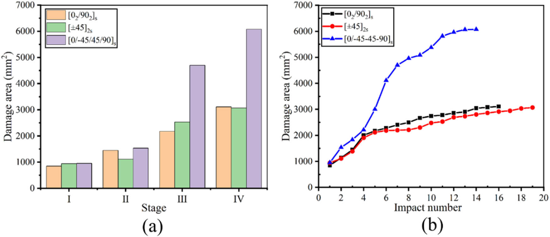
Projected delamination areas of the specimens: (a) damage area at the four stages and (b) damage area vs impact number curves.
To have a close understanding of the damage mechanism, the micro-damage morphology of the central impact region of the damaged specimens is illustrated in Figure 8, as detected by the SEM technique. The damage modes, including matrix cracking, fiber/matrix debonding, delamination, and fiber breakage, can be clearly distinguished for the three stacking specimens. The matrix cracking propagates along the fiber orientation due to the debonding between fiber and matrix, or extends through the thickness resulted from tension or shear. The delamination is easily found between two adjacent plies with different fiber orientations, as shown by SEM images. The fiber breakage occurs when the local high stress induced in the damaged region exceeds the load bearing capability of the fibers.

Micro-damage morphology of the three stacking sequences.
3.4 Damage accumulation evaluation
To assess the damage cumulative degree of the studied laminates subjected to repeated low velocity impacts from no damage to perforation, the damage accumulation parameters DI and DI-B are applied in this study, respectively. The damage variable DI was proposed by Belingardi et al. (35) to explore the damage accumulation in thick laminates from first impact to perforation. The parameter DI can not only reflect the trend of energy dissipation related to the impact number but also distinguish the penetration from the stable damage accumulation process. The variable DI is expressed as
where d max is the maximum displacement of the force–displacement curve in each impact event, and d p is the critical displacement of the force–displacement curve at perforation. The parameter DD is defined as the absorbed energy fraction for each impact, namely,
where E i and E a are the impact energy and absorbed energy, respectively. The calculated DI with respect to the impact number of the three stacking laminates under repeated impacts is displayed in Figure 9(a). Almost an invisible reduction in the DI is distinguished for the three studied laminates at first few impacts, caused by the decrease in DD. Subsequently, the variable DI first increases slowly and then rapidly with the rise in impact number for all the studied laminates, which is closely associated with the damage modes induced during the repeated impact process. Compared to the matrix cracking and delamination damage patterns dominated in the laminates at first few impacts, the damage of fiber breakage induced in subsequent impacts causes large degradation of the mechanical performance, leading to the damage accumulation more rapidly. In general, the variable DI of the laminate with the ply orientation of [0°2/90°2]s is larger than that of the other two laminates, which indicates that the impact resistance of the sandwich-like laminate is weaker with severe damage accumulated in the laminate during repeated impacts. Moreover, the variable DI of the laminate with the stacking sequence of [0°/−45°/45°/90°]s is smaller than that of the laminate with the lay-up sequence of [±45°]2s before the 7th impact, which demonstrates that the impact resistance of the quasi-isotropic laminate is better at initial several impacts. While, the variable DI of the quasi-isotropic laminate increases rapidly in subsequent impacts, even larger than that of the angle-ply laminate. This phenomenon proves that the impact performance is better for the angle-ply laminate in subsequent impacts. The damage variable DI can reflect the tendency of the damage accumulation of the three studied laminates, and identify the occurrence of perforation. However, variable DI fails to meet the logic of damage index for characterizing the damage accumulation monotonically increasing from zero to one.

Damage accumulation characterized by different damage variables: (a) DI and (b) DI-B.
The damage variable DI-B developed by Liao et al. (17) is employed to characterize the damage accumulation more generally. Based on the impact bending stiffness reduction rate R s and normalized maximum displacement, the variable DI-B is defined as follows:
where R s can be calculated as follows:
where k 0 stands for the initial impact bending stiffness at first impact, k f represents the bending stiffness at perforation, and k i is the bending stiffness at the ith impact. The tendency of the damage variable DI-B with respect to the impact number is shown in Figure 9(b). It is easily observed that the DI-B monotonically increases from zero to one attributed to the bending stiffness reduction rate monotonically increasing from zero to one. The occurrence of matrix cracking and delamination, damage accumulation phase dominated by matrix cracking and delamination, appearance of fiber breakage, damage accumulation phase dominated by fiber breakage, and perforation are distinguished for the studied laminates subjected to repeated impacts. Compared to the other two composite laminates, it is evident that more impact numbers are required to reach the value one of the DI-B index for the angle-ply laminate, which indicates the damage tolerance of the angle-ply laminate is higher, i.e., the angle-ply laminate can withstand more repeated impacts and thus dissipate more impact energy. Furthermore, the damage accumulation of the angle-ply laminate is the slowest among the three studied composite laminates on the whole, which demonstrates that the impact resistance of this laminate is the best. The slower the increase in damage accumulation, the lesser the damage caused at each impact event, and hence better the impact resistance. Compared with the sandwich-like laminate, the damage propagation through the thickness can be limited or stopped by alternating fiber orientation in adjacent plies for the angle-ply laminate, thus less damage is induced at each impact event. Compared to the synergistic action of the severe fiber breakage development and continuous delamination extension in the quasi-isotropic laminate after the appearance of fiber breakage, the damage accumulation in the angle-ply laminate is mainly induced by the stable fiber breakage propagation due to the delamination saturation. As a consequence, the damage accumulation of the angle-ply laminate is relatively slower and stabler. Therefore, the angle-ply laminate possesses higher impact resistance and damage tolerance than the quasi-isotropic laminate.
4 Conclusion
The dynamic response and damage accumulation of glass fiber-reinforced composite laminates subjected to repeated low velocity impacts were investigated in this study. The purpose of this work was to analyze the influence of lay-up sequences on the impact resistance of this composite under repeated impacts. The composite laminates with three different lay-up sequences, including sandwich-like, angle-ply, and quasi-isotropic configurations, were impacted at 20 J in each impact until perforation. The following conclusions can be drawn:
The force–time/maximum displacement curves show that the matrix cracking, delamination initiation, fiber breakage, and perforation are the four typical impact characteristics describing the damage evolution of repeated impacts. Compared with a roughly circular shape for the quasi-isotropic laminate, the delamination of the sandwich-like and angle-ply laminates primarily develops in an elliptical shape with the major axis along the stacking direction of the outermost layer during repeated impacts.
The impact resistance of the sandwich-like laminate is the weakest among the three stacking structures with the lowest peak force, the highest maximum displacement, and the smallest bending stiffness.
Compared with the angle-ply laminate, the impact performance of the quasi-isotropic is better with larger bending stiffness before the appearance of fiber breakage. On the contrary, the angle-ply laminate possesses higher impact resistance and damage tolerance with relatively slower damage accumulation at subsequent impacts.
Compared with the damage variable DI, the DI-B meets the logic of damage index monotonically increasing from zero to one, and can characterize the damage accumulation and perforation simultaneously for the current studied composite laminates.
-
Funding information: This work was supported by the National Natural Science Foundation of China (12162013), the Natural Science Foundation of Jiangxi Province, China (20212BAB214013).
-
Author contributions: Zhaogang Yu: writing – original draft, conducting the experiment, and characterization; Kun Liu: writing – review and editing; Zhen Tao: writing – review and editing; Jangtao Zhang: writing – review and editing; Hao Li: writing – review and editing and project administration.
-
Conflict of interest: The authors state no conflict of interest.
-
Data availability statement: The data that support the findings of this study are available from the corresponding author upon reasonable request.
References
(1) Rani M, Choudhary P, Krishnan V, Zafar S. A review on recycling and reuse methods for carbon fiber/glass fiber composites waste from wind turbine blades. Compos Part B-Eng. 2021;215:108768.10.1016/j.compositesb.2021.108768Search in Google Scholar
(2) Rubino F, Nisticò A, Tucci F, Carlone P. Marine application of fiber reinforced composites: A review. J Mar Sci Eng. 2020;8(1):26.10.3390/jmse8010026Search in Google Scholar
(3) Li J, Durandet Y, Huang X, Sun G, Ruan D. Additively manufactured fiber-reinforced composites: A review of mechanical behavior and opportunities. J Mater Sci Technol. 2022;119:219–44.10.1016/j.jmst.2021.11.063Search in Google Scholar
(4) Giridharan R. Preparation and property evaluation of Glass/Ramie fibers reinforced epoxy hybrid composites. Compos Part B-Eng. 2019;167:342–5.10.1016/j.compositesb.2018.12.049Search in Google Scholar
(5) Gemi DS, Şahin ÖS, Gemi L. Experimental investigation of the effect of diameter upon low velocity impact response of glass fiber reinforced composite pipes. Compos Struct. 2021;275:114428.10.1016/j.compstruct.2021.114428Search in Google Scholar
(6) Boukar A, Corn S, Slangen PR, Ienny P. Finite element modelling of low velocity impact test applied to biaxial glass fiber reinforced laminate composites. Int J Impact Eng. 2022;165:104218.10.1016/j.ijimpeng.2022.104218Search in Google Scholar
(7) Chen D, Luo Q, Meng M, Li Q, Sun G. Low velocity impact behavior of interlayer hybrid composite laminates with carbon/glass/basalt fibres. Compos Part B-Eng. 2019;176:107191.10.1016/j.compositesb.2019.107191Search in Google Scholar
(8) Daelemans L, Cohades A, Meireman T, Beckx J, Spronk S, Kersemans M, et al. Electrospun nanofibrous interleaves for improved low velocity impact resistance of glass fibre reinforced composite laminates. Mater Design. 2018;141:170–84.10.1016/j.matdes.2017.12.045Search in Google Scholar
(9) Barouni AK, Dhakal HN. Damage investigation and assessment due to low-velocity impact on flax/glass hybrid composite plates. Compos Struct. 2019;226:111224.10.1016/j.compstruct.2019.111224Search in Google Scholar
(10) Ozdemir O, Oztoprak N, Kandas H. Single and repeated impact behaviors of bio-sandwich structures consisting of thermoplastic face sheets and different balsa core thicknesses. Compos Part B-Eng. 2018;149:49–57.10.1016/j.compositesb.2018.05.016Search in Google Scholar
(11) Macdonald H, Nash D, Stack MM. Repeated impact of simulated hail ice on glass fibre composite materials. Wear. 2019;432:102926.10.1016/j.wear.2019.06.001Search in Google Scholar
(12) Arikan V, Sayman O. Comparative study on repeated impact response of E-glass fiber reinforced polypropylene & epoxy matrix composites. Compos Part B-Eng. 2015;83:1–6.10.1016/j.compositesb.2015.08.051Search in Google Scholar
(13) Li L, Sun L, Wang T, Kang N, Cao W. Repeated low-velocity impact response and damage mechanism of glass fiber aluminium laminates. Aerosp Sci Technol. 2019;84:995–1010.10.1016/j.ast.2018.11.038Search in Google Scholar
(14) Balcı O, Çoban O, Bora MÖ, Akagündüz E, Yalçin EB. Experimental investigation of single and repeated impacts for repaired honeycomb sandwich structures. Mater Sci Eng A-Struct. 2017;682:23–30.10.1016/j.msea.2016.11.030Search in Google Scholar
(15) Kashani MH, Sadighi M, Lalehpour A, Alderliesten RC. The effect of impact energy division over repeated low-velocity impact on fiber metal laminates. J Compos Mater. 2015;49(6):635–46.10.1177/0021998314521476Search in Google Scholar
(16) Dogan A. Single and repeated low-velocity impact response of E-glass fiber-reinforced epoxy and polypropylene composites for different impactor shapes. J Thermoplast Compos. 2022;35(3):320–36.10.1177/0892705719886911Search in Google Scholar
(17) Liao B, Zhou J, Li Y, Wang P, Xi L, Gao R, et al. Damage accumulation mechanism of composite laminates subjected to repeated low velocity impacts. Int J Mech Sci. 2020;182:105783.10.1016/j.ijmecsci.2020.105783Search in Google Scholar
(18) Atas C, Dogan A. An experimental investigation on the repeated impact response of glass/epoxy composites subjected to thermal ageing. Compos Part B-Eng. 2015;75:127–34.10.1016/j.compositesb.2015.01.032Search in Google Scholar
(19) Zhu L, Guo K, Li Y, Yu TX, Zhou Q. Experimental study on the dynamic behaviour of aluminium foam sandwich plates under single and repeated impacts at low temperature. Int J Impact Eng. 2018;114:123–32.10.1016/j.ijimpeng.2017.12.001Search in Google Scholar
(20) Coelho SRM, Reis PNB, Ferreira JAM, Pereira AM. Effects of external patch configuration on repaired composite laminates subjected to multi-impacts. Compos Struct. 2017;168:259–65.10.1016/j.compstruct.2017.02.069Search in Google Scholar
(21) Sun Z, Li C, Tie Y. Experimental and numerical investigations on damage accumulation and energy dissipation of patch-repaired CFRP laminates under repeated impacts. Mater Design. 2021;202:109540.10.1016/j.matdes.2021.109540Search in Google Scholar
(22) Sadighi M, Tooski MY, Alderliesten RC. An experimental study on the low velocity impact resistance of fibre metal laminates under successive impacts with reduced energies. Aerosp Sci Technol. 2017;67:54–61.10.1016/j.ast.2017.03.042Search in Google Scholar
(23) Tian S, Zhou Z. New criteria for simulating failure under multiple impacts of the same total energy on glass fiber reinforced aluminum alloy laminates. Mater Design. 2016;102:142–50.10.1016/j.matdes.2016.04.024Search in Google Scholar
(24) Akatay A, Bora MÖ, Çoban O, Fidan S, Tuna V. The influence of low velocity repeated impacts on residual compressive properties of honeycomb sandwich structures. Compos Struct. 2015;125:425–33.10.1016/j.compstruct.2015.02.057Search in Google Scholar
(25) Guo K, Zhu L, Li Y, Yu TX, Shenoi A, Zhou Q. Experimental investigation on the dynamic behaviour of aluminum foam sandwich plate under repeated impacts. Compos Struct. 2018;200:298–305.10.1016/j.compstruct.2018.05.148Search in Google Scholar
(26) Garzon-Hernandez S, Garcia-Gonzalez D, Arias A. Multi-impact mechanical behaviour of short fibre reinforced composites. Compos Struct. 2018;202:241–52.10.1016/j.compstruct.2018.01.070Search in Google Scholar
(27) Saleh MN, El-Dessouky HM, Saeedifar M, De Freitas ST, Scaife RJ, Zarouchas D. Compression after multiple low velocity impacts of NCF, 2D and 3D woven composites. Compos Part A-Appl Sci Manuf. 2019;125:105576.10.1016/j.compositesa.2019.105576Search in Google Scholar
(28) Sevkat E, Liaw B, Delale F, Raju BB. Effect of repeated impacts on the response of plain-woven hybrid composites. Compos Part B-Eng. 2010;41(5):403–13.10.1016/j.compositesb.2010.01.001Search in Google Scholar
(29) David-West OS, Nash DH, Banks WM. An experimental study of damage accumulation in balanced CFRP laminates due to repeated impact. Compos Struct. 2008;83(3):247–58.10.1016/j.compstruct.2007.04.015Search in Google Scholar
(30) Atas C, Icten BM, Küçük M. Thickness effect on repeated impact response of woven fabric composite plates. Compos Part B-Eng. 2013;49:80–5.10.1016/j.compositesb.2013.01.019Search in Google Scholar
(31) Paolino DS, Cavatorta MP, Belingardi G. Effect of thickness on the damage tolerance of glass/epoxy laminates subject to repeated impacts. P I Mech Eng C-J Mech Eng Sci. 2018;232(8):1363–73.10.1177/0954406217737582Search in Google Scholar
(32) Rezasefat M, Gonzalez-Jimenez A, Giglio M, Manes A. Numerical study on the dynamic progressive failure due to low-velocity repeated impacts in thin CFRP laminated composite plates. Thin Wall Struct. 2021;167:108220.10.1016/j.tws.2021.108220Search in Google Scholar
(33) González EV, Maimí P, Camanho PP, Lopes CS, Blanco N. Effects of ply clustering in laminated composite plates under low-velocity impact loading. Compos Sci Technol. 2011;71(6):805–17.10.1016/j.compscitech.2010.12.018Search in Google Scholar
(34) Papa I, Formisano A, Lopresto V, Langella A. Low velocity impact behaviour of reinforced plastic laminates: Indentation and penetration laws validated for different fibres and matrices. Compos Part B-Eng. 2019;164:61–6.10.1016/j.compositesb.2018.11.070Search in Google Scholar
(35) Belingardi G, Cavatorta MP, Paolino DS. On the rate of growth and extent of the steady damage accumulation phase in repeated impact tests. Compos Sci Technol. 2009;69(11–12):1693–8.10.1016/j.compscitech.2008.10.023Search in Google Scholar
(36) Fragassa C, Pavlovic A, Santulli C. Mechanical and impact characterisation of flax and basalt fibre vinyl ester composites and their hybrids. Compos Part B-Eng. 2018;137:247–59.10.1016/j.compositesb.2017.01.004Search in Google Scholar
(37) Quaresimin M, Ricotta M, Martello L, Mian S. Energy absorption in composite laminates under impact loading. Compos Part B-Eng. 2013;44(1):133–40.10.1016/j.compositesb.2012.06.020Search in Google Scholar
(38) Wang C, Chen Z, Silberschmidt VV, Roy A. Damage accumulation in braided textiles-reinforced composites under repeated impacts: Experimental and numerical studies. Compos Struct. 2018;204:256–67.10.1016/j.compstruct.2018.07.084Search in Google Scholar
(39) Caminero MA, García-Moreno I, Rodríguez GP. Damage resistance of carbon fibre reinforced epoxy laminates subjected to low velocity impact: Effects of laminate thickness and ply-stacking sequence. Polym Test. 2017;63:530–41.10.1016/j.polymertesting.2017.09.016Search in Google Scholar
(40) Lebaupin Y, Hoang TQT, Chauvin M, Touchard F. Influence of the stacking sequence on the low-energy impact resistance of flax/PA11 composite. J Compos Mater. 2019;53(22):3187–98.10.1177/0021998319837339Search in Google Scholar
(41) Lopes CS, Seresta O, Coquet Y, Gürdal Z, Camanho PP, Thuis B. Low-velocity impact damage on dispersed stacking sequence laminates. Part I: Experiments. Compos Sci Technol. 2009;69(7–8):926–36.10.1016/j.compscitech.2009.02.009Search in Google Scholar
(42) Sebaey TA, González EV, Lopes CS, Blanco N, Costa J. Damage resistance and damage tolerance of dispersed CFRP laminates: Effect of ply clustering. Compos Struct. 2013;106:96–103.10.1016/j.compstruct.2013.05.052Search in Google Scholar
(43) Azouaoui K, Rechak S, Azari Z, Benmedakhene S, Laksimi A, Pluvinage G. Modelling of damage and failure of glass/epoxy composite plates subject to impact fatigue. Int J fatigue. 2001;23(10):877–85.10.1016/S0142-1123(01)00050-0Search in Google Scholar
(44) Tooski MY, Alderliesten RC, Ghajar R, Khalili SMR. Experimental investigation on distance effects in repeated low velocity impact on fiber–metal laminates. Compos Struct. 2013;99:31–40.10.1016/j.compstruct.2012.11.045Search in Google Scholar
© 2023 the author(s), published by De Gruyter
This work is licensed under the Creative Commons Attribution 4.0 International License.
Articles in the same Issue
- Research Articles
- Chitosan nanocomposite film incorporating Nigella sativa oil, Azadirachta indica leaves’ extract, and silver nanoparticles
- Effect of Zr-doped CaCu3Ti3.95Zr0.05O12 ceramic on the microstructure, dielectric properties, and electric field distribution of the LDPE composites
- Effects of dry heating, acetylation, and acid pre-treatments on modification of potato starch with octenyl succinic anhydride (OSA)
- Loading conditions impact on the compression fatigue behavior of filled styrene butadiene rubber
- Characterization and compatibility of bio-based PA56/PET
- Study on the aging of three typical rubber materials under high- and low-temperature cyclic environment
- Numerical simulation and experimental research of electrospun polyacrylonitrile Taylor cone based on multiphysics coupling
- Experimental investigation of properties and aging behavior of pineapple and sisal leaf hybrid fiber-reinforced polymer composites
- Influence of temperature distribution on the foaming quality of foamed polypropylene composites
- Enzyme-catalyzed synthesis of 4-methylcatechol oligomer and preliminary evaluations as stabilizing agent in polypropylene
- Molecular dynamics simulation of the effect of the thermal and mechanical properties of addition liquid silicone rubber modified by carbon nanotubes with different radii
- Incorporation of poly(3-acrylamidopropyl trimethylammonium chloride-co-acrylic acid) branches for good sizing properties and easy desizing from sized cotton warps
- Effect of matrix composition on properties of polyamide 66/polyamide 6I-6T composites with high content of continuous glass fiber for optimizing surface performance
- Preparation and properties of epoxy-modified thermosetting phenolic fiber
- Thermal decomposition reaction kinetics and storage life prediction of polyacrylate pressure-sensitive adhesive
- Effect of different proportions of CNTs/Fe3O4 hybrid filler on the morphological, electrical and electromagnetic interference shielding properties of poly(lactic acid) nanocomposites
- Doping silver nanoparticles into reverse osmosis membranes for antibacterial properties
- Melt-blended PLA/curcumin-cross-linked polyurethane film for enhanced UV-shielding ability
- The affinity of bentonite and WO3 nanoparticles toward epoxy resin polymer for radiation shielding
- Prolonged action fertilizer encapsulated by CMC/humic acid
- Preparation and experimental estimation of radiation shielding properties of novel epoxy reinforced with Sb2O3 and PbO
- Fabrication of polylactic acid nanofibrous yarns for piezoelectric fabrics
- Copper phenyl phosphonate for epoxy resin and cyanate ester copolymer with improved flame retardancy and thermal properties
- Synergistic effect of thermal oxygen and UV aging on natural rubber
- Effect of zinc oxide suspension on the overall filler content of the PLA/ZnO composites and cPLA/ZnO composites
- The role of natural hybrid nanobentonite/nanocellulose in enhancing the water resistance properties of the biodegradable thermoplastic starch
- Performance optimization of geopolymer mortar blending in nano-SiO2 and PVA fiber based on set pair analysis
- Preparation of (La + Nb)-co-doped TiO2 and its polyvinylidene difluoride composites with high dielectric constants
- Effect of matrix composition on the performance of calcium carbonate filled poly(lactic acid)/poly(butylene adipate-co-terephthalate) composites
- Low-temperature self-healing polyurethane adhesives via dual synergetic crosslinking strategy
- Leucaena leucocephala oil-based poly malate-amide nanocomposite coating material for anticorrosive applications
- Preparation and properties of modified ammonium polyphosphate synergistic with tris(2-hydroxyethyl) isocynurate for flame-retardant LDPE
- Thermal response of double network hydrogels with varied composition
- The effect of coated calcium carbonate using stearic acid on the recovered carbon black masterbatch in low-density polyethylene composites
- Investigation of MXene-modified agar/polyurethane hydrogel elastomeric repair materials with tunable water absorption
- Damping performance analysis of carbon black/lead magnesium niobite/epoxy resin composites
- Molecular dynamics simulations of dihydroxylammonium 5,5′-bistetrazole-1,1′-diolate (TKX-50) and TKX-50-based PBXs with four energetic binders
- Preparation and characterization of sisal fibre reinforced sodium alginate gum composites for non-structural engineering applications
- Study on by-products synthesis of powder coating polyester resin catalyzed by organotin
- Ab initio molecular dynamics of insulating paper: Mechanism of insulating paper cellobiose cracking at transient high temperature
- Effect of different tin neodecanoate and calcium–zinc heat stabilizers on the thermal stability of PVC
- High-strength polyvinyl alcohol-based hydrogel by vermiculite and lignocellulosic nanofibrils for electronic sensing
- Impacts of micro-size PbO on the gamma-ray shielding performance of polyepoxide resin
- Influence of the molecular structure of phenylamine antioxidants on anti-migration and anti-aging behavior of high-performance nitrile rubber composites
- Fiber-reinforced polyvinyl alcohol hydrogel via in situ fiber formation
- Preparation and performance of homogenous braids-reinforced poly (p-phenylene terephthamide) hollow fiber membranes
- Synthesis of cadmium(ii) ion-imprinted composite membrane with a pyridine functional monomer and characterization of its adsorption performance
- Impact of WO3 and BaO nanoparticles on the radiation shielding characteristics of polydimethylsiloxane composites
- Comprehensive study of the radiation shielding feature of polyester polymers impregnated with iron filings
- Preparation and characterization of polymeric cross-linked hydrogel patch for topical delivery of gentamicin
- Mechanical properties of rCB-pigment masterbatch in rLDPE: The effect of processing aids and water absorption test
- Pineapple fruit residue-based nanofibre composites: Preparation and characterizations
- Effect of natural Indocalamus leaf addition on the mechanical properties of epoxy and epoxy-carbon fiber composites
- Utilization of biosilica for energy-saving tire compounds: Enhancing performance and efficiency
- Effect of capillary arrays on the profile of multi-layer micro-capillary films
- A numerical study on thermal bonding with preheating technique for polypropylene microfluidic device
- Development of modified h-BN/UPE resin for insulation varnish applications
- High strength, anti-static, thermal conductive glass fiber/epoxy composites for medical devices: A strategy of modifying fibers with functionalized carbon nanotubes
- Effects of mechanical recycling on the properties of glass fiber–reinforced polyamide 66 composites in automotive components
- Bentonite/hydroxyethylcellulose as eco-dielectrics with potential utilization in energy storage
- Study on wall-slipping mechanism of nano-injection polymer under the constant temperature fields
- Synthesis of low-VOC unsaturated polyester coatings for electrical insulation
- Enhanced apoptotic activity of Pluronic F127 polymer-encapsulated chlorogenic acid nanoparticles through the PI3K/Akt/mTOR signaling pathway in liver cancer cells and in vivo toxicity studies in zebrafish
- Preparation and performance of silicone-modified 3D printing photosensitive materials
- A novel fabrication method of slippery lubricant-infused porous surface by thiol-ene click chemistry reaction for anti-fouling and anti-corrosion applications
- Development of polymeric IPN hydrogels by free radical polymerization technique for extended release of letrozole: Characterization and toxicity evaluation
- Tribological characterization of sponge gourd outer skin fiber-reinforced epoxy composite with Tamarindus indica seed filler addition using the Box–Behnken method
- Stereocomplex PLLA–PBAT copolymer and its composites with multi-walled carbon nanotubes for electrostatic dissipative application
- Enhancing the therapeutic efficacy of Krestin–chitosan nanocomplex for cancer medication via activation of the mitochondrial intrinsic pathway
- Variation in tungsten(vi) oxide particle size for enhancing the radiation shielding ability of silicone rubber composites
- Damage accumulation and failure mechanism of glass/epoxy composite laminates subjected to repeated low velocity impacts
- Gamma-ray shielding analysis using the experimental measurements for copper(ii) sulfate-doped polyepoxide resins
- Numerical simulation into influence of airflow channel quantities on melt-blowing airflow field in processing of polymer fiber
- Cellulose acetate oleate-reinforced poly(butylene adipate-co-terephthalate) composite materials
- Radiation shielding capability and exposure buildup factor of cerium(iv) oxide-reinforced polyester resins
- Recyclable polytriazole resins with high performance based on Diels-Alder dynamic covalent crosslinking
- Adsorption and recovery of Cr(vi) from wastewater by Chitosan–Urushiol composite nanofiber membrane
- Comprehensive performance evaluation based on electromagnetic shielding properties of the weft-knitted fabrics made by stainless steel/cotton blended yarn
- Review Articles
- Preparation and application of natural protein polymer-based Pickering emulsions
- Wood-derived high-performance cellulose structural materials
- Flammability properties of polymers and polymer composites combined with ionic liquids
- Polymer-based nanocarriers for biomedical and environmental applications
- A review on semi-crystalline polymer bead foams from stirring autoclave: Processing and properties
- Rapid Communication
- Preparation and characterization of magnetic microgels with linear thermosensitivity over a wide temperature range
- Special Issue: Biodegradable and bio-based polymers: Green approaches (Guest Editors: Kumaran Subramanian, A. Wilson Santhosh Kumar, and Venkatajothi Ramarao)
- Synthesis and characterization of proton-conducting membranes based on bacterial cellulose and human nail keratin
- Fatigue behaviour of Kevlar/carbon/basalt fibre-reinforced SiC nanofiller particulate hybrid epoxy composite
- Effect of citric acid on thermal, phase morphological, and mechanical properties of poly(l-lactide)-b-poly(ethylene glycol)-b-poly(l-lactide)/thermoplastic starch blends
- Dose-dependent cytotoxicity against lung cancer cells via green synthesized ZnFe2O4/cellulose nanocomposites