
Effect of capillary arrays on the profile of multi-layer micro-capillary films
-
Jianhua Xiao
 ,
Ru Yang
,
Ru Yang

Abstract
Multi-layer micro-capillary films (MCFs) have broad application prospects in the micro-fluid field. These films consist of two-dimensional arrays of hollow microcapillaries. The arrangements of hollow microcapillary arrays in extrusion die strongly influence the shape and size of multi-layer MCFs. However, most of the studies focus on a single-layer film. In this study, the models of multi-layer MCF extrusion die with hollow capillary arrays from one layer to four layers have been modeled. Numerical simulations show that when the hollow capillary arrays in different layers are aligned, the aspect ratio of the capillary is smaller and the flow resistance is small, so this kind of multi-layer MCF is suitable for micro-reactor and melt pump. When the hollow capillary arrays in different layers are non-aligned, the aspect ratio of the capillary is relatively larger and the specific surface is bigger, so this kind of multi-layer MCF has a high capability of heat exchange and is suitable for micro heat exchangers.
1 Introduction
Micro-capillary film (MCF) extrusion is a novel process for the manufacturing of continuous MCFs. It was put forward by Hallmark (1,2) in 2003. In this process (B. Hallmark, April 2007, Apparatus and method for producing a film having a tear guiding region, and an extruded film having such a tear guided region, U.S. patent 20080248147A1), the polymer is extruded through an array of hollow extrusion die. Then, in the holes of the extrusion die, a high-pressure gas is injected into the polymer melt to form continuous MCFs (Figure 1).
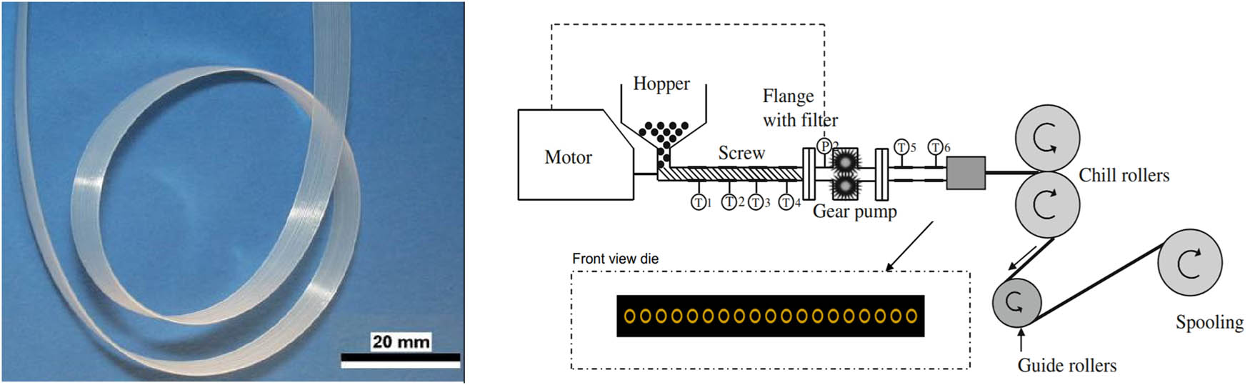
MCFs and the MCF extrusion process.
The low density polyethylene (LDPE) film, polyvinylidene fluoride film, and fluorinated ethylene propylene copolymer film with 19-, 42- (3), or 10 capillaries have been fabricated with 30−500 μm capillaries (4). The advantages of MCFs include thin walls, good optical properties, large A/V, small capillary diameter, plug flow, multi-capillaries, simple fluidics, disposability, and low cost. They have potential applications in photonics heat exchange, non-invasive tracking, adsorbent material, fast kinetics, bioprocessing, and micro-reactor technology.
The MCF can be effectively used for micro-heat exchanger, micro reactions, and bioprocessing. The efficacy of heat transfer of the MCF is close to metallic microfluidic devices (5). It provides an effective means of either heating or cooling fluids, or removing heat from a hot surface (6). It has been successfully used to fabricate plastic solar collectors (7) and made into spirals or solid discs adopted in microreactors (8).
The MCF can also be effectively used for micro-flow, drug delivery (NS Grasman, Microcapillary polymer films for drug delivery, May 2017, US patent 20170119692A1), mass transfer, and purification. The fluid flow in a capillary tube exhibits high-performance “plug” features (9). It can be designed for miniaturized microfluidic biosensing devices (10), CECs in water, and viruses and bacteria removal devices (11), phase change materials (R J Koopmans, MCFs containing phase change materials, Jan 2013, US patent 20140113112A1), and superparamagnetic nanoparticle purification (12). The purities are typically more than 95% (13).
The MCF can also be used in bioanalytical techniques, such as rapid point-of-care quantitation of bacterial (14), semi-quantitative determination of hydrogen peroxide (15), protein chromatography, multiplex immunoassays (16), and fluorescence immunoassay quantitation of Escherichia coli optical microfluidic test (17).
However, in the aforementioned studies, the MCF is a single-layer film. A multi-layer MCF has higher mechanical strength than the single-layer MCF. It has potential prospective applications in biomedical, life science, engineering science, and physical science. It has been fabricated by heat melding of multiple single-layer MCFs to form MCF monoliths (18). Some patents introduced an extrusion die for manufacturing multi-layer MCFs (D Joseph, 7 Nov 2018, System and method for producing a multi-layer MCF, EP Patent 2867000B1). However, the influence of the arrangement of capillary arrays on the shape and size of the external film has not been studied systematically. In this study, the numerical simulation method is adopted to study the multi-layer MCF extrusion process.
Section 1 describes the development, process, and application of an MCF. Section 2 details the modeling, meshing, rheological parameters, constitutive equations, and boundary conditions used in the numerical simulation of multiple-layer MCFs with typical 9 capillaries in the same layer. Section 3 discusses the effect of the arrangement of capillary arrays on the shape and size of the external film or internal capillary within single- and multi-layer MCF.
2 Numerical simulation
2.1 Models of single- and multi-layer MCFs
The cross section of single- and multi-layer MCF models modeled in this study have nine types of hollow capillary arrays from one layer to four layers (Figure 2). Some capillary arrays in different layers are aligned, and some of them are non-aligned.
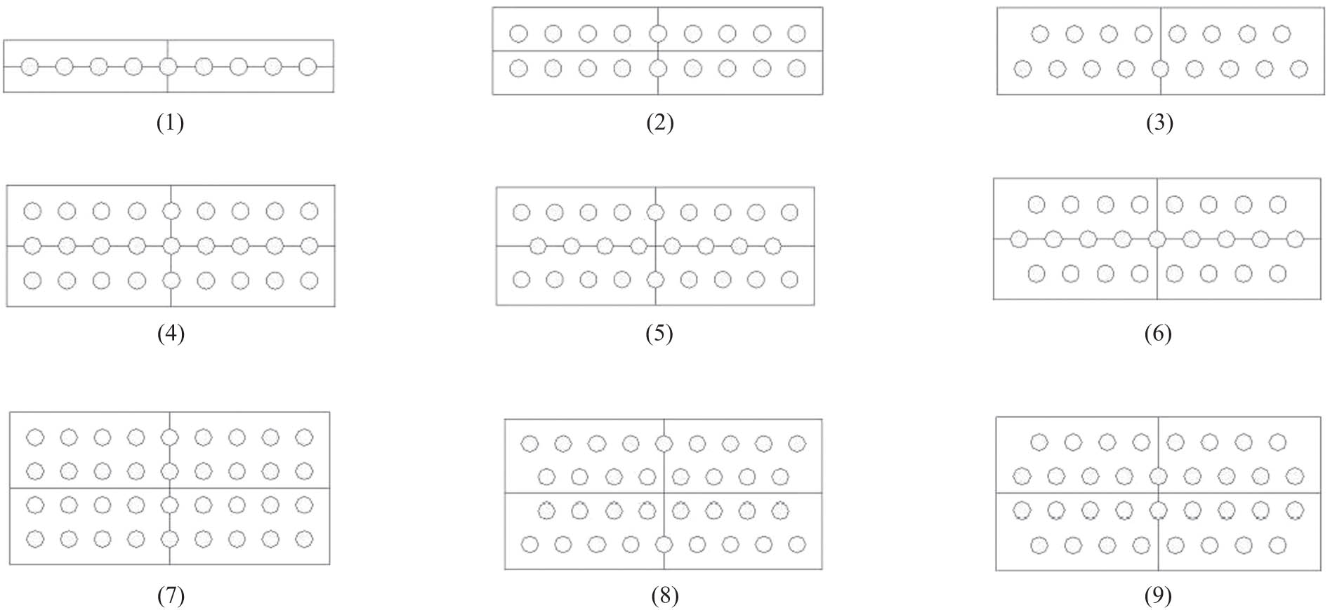
Cross section of single- and multi-layer MCF models with different capillary arrays. (1) Single-layer MCF with 9 capillaries. (2) Bi-layer MCF with 18 capillaries. (3) Bi-layer MCF with 17 capillaries. (4) Three-layer MCF with 27 capillaries. (5) Three-layer MCF with 26 capillaries. (6) Three-layer MCF with 25 capillaries. (7) Four-layer MCF with 36 capillaries. (8) Four-layer MCF with 16 capillaries in the middle. (9) Four-layer MCF with 18 capillaries in the middle.
The diameter of the capillaries is 0.50 mm, and the spacing between capillaries is 0.50 mm. The width of the models is 9.50 mm. The thickness of the MCF model, shown in Figure 2(1), (3), (4)–(6), and (7)–(9), are 1.50, 2.50, 3.50, and 4.50 mm, respectively.
The 3D models were established (Figure 3). There are outer and inner domains in the models: one domain represents inside the extrusion die (length = 2 mm), and the other domain represents outside the die (length = 7 mm). 1/4 bisymmetric axis models are used for saving the CPU-solving times.
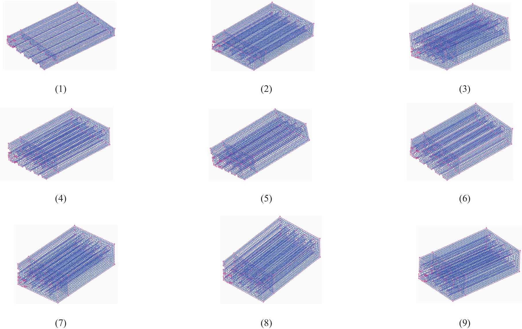
1/4 bisymmetric axis model and mesh of single- and multi-layer MCF models. (1) Single-layer MCF with 9 capillaries. (2) Bi-layer MCF with 18 capillaries. (3) Bi-layer MCF with 17 capillaries. (4) Three-layer MCF with 27 capillaries. (5) Three-layer MCF with 26 capillaries. (6) Three-layer MCF with 25 capillaries. (7) Four-layer MCF with 36 capillaries. (8) Four-layer MCF with 16 capillaries in the middle. (9) Four-layer MCF with 18 capillaries in the middle.
Detailed information on MCF models is shown in Table 1. Porosity is the ratio of the area of capillaries on the cross section to the area of the whole MCF film. From single-layer to four-layer MCF with capillaries aligned, the porosities are 12.39, 14.87, 15.93, and 16.52%. Under the same layer numbers, the films with aligned capillaries have more holes than nonaligned capillaries. The number of meshes for each model is about 10,000. The geometric models were meshed using Gambit software.
Width, thickness, porosity, and mesh node of single- and multi-layer MCF models
| Model | MCF | Width (mm) | Thickness (mm) | Capillary number | Capillary array | Porosity of die (%) | Mesh node | Solving time (s) |
|---|---|---|---|---|---|---|---|---|
| 1 | Single-layer MCF with 9 capillaries | 9.50 | 1.50 | 9 | Aligned | 12.39 | 10,125 | 1,353 |
| 2 | Bi-layer MCF with 18 capillaries | 9.50 | 2.50 | 18 | Aligned | 14.87 | 10,107 | 2,477 |
| 3 | Bi-layer MCF with 17 capillaries | 9.50 | 2.50 | 17 | Non-aligned | 14.04 | 13,392 | 4,821 |
| 4 | Three-layer MCF with 27 capillaries | 9.50 | 3.50 | 27 | Aligned | 15.93 | 11,241 | 1,876 |
| 5 | Three-layer MCF with 26 capillaries | 9.50 | 3.50 | 26 | Non-aligned | 15.34 | 13,872 | 1,942 |
| 6 | Three-layer MCF with 25 capillaries | 9.50 | 3.50 | 25 | Non-aligned | 14.76 | 10,116 | 2,147 |
| 7 | Four-layer MCF with 36 capillaries | 9.50 | 4.50 | 36 | Aligned | 16.52 | 13,833 | 3,167 |
| 8 | Four-layer MCF with 16 capillaries in the middle | 9.50 | 4.50 | 34 | Non-aligned | 15.60 | 13,338 | 7,106 |
| 9 | Four-layer MCF with 18 capillaries in the middle | 9.50 | 4.50 | 34 | Non-aligned | 15.60 | 13,545 | 15,305 |
2.2 Material parameters
In this work, a generalized Newtonian constitutive equation, the Carreau–Yasuda model in Eq. 1 is used to describe LDPE rheology:
where
2.3 Boundary condition sets
Boundary conditions inflow, wall, free surface, outflow, and plane of symmetry are set in Ansys software. The inflow boundary is a fully developed flow with a total volumetric flow rate of 5 cm3·s−1. At each end of the model, a stretch force has been exerted. The geometric model and boundary conditions of the two-layer MCF are shown in Figure 4, and the same boundary conditions are set in all nine models.
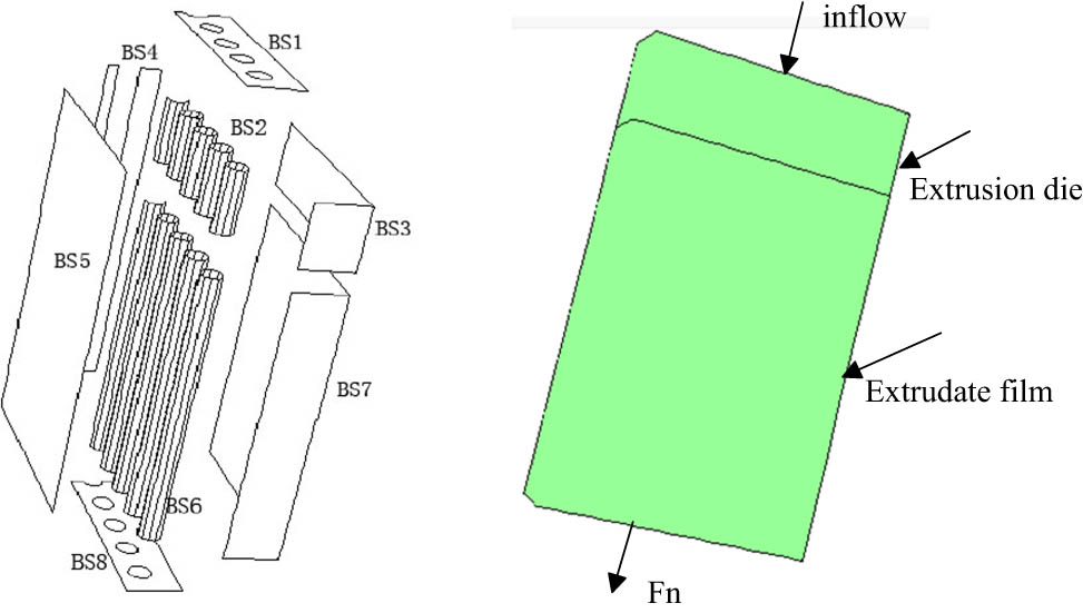
1/4 bisymmetric axis model of the bi-layer MCF with 18 capillaries used in the simulation. BS1 is the inflow, Q = 5 cm3·s−1. BS2 and BS3 are, respectively, identified as the wall of the gas injection die and polymer extrusion dies. V n = 0 and V s = 0. BS4 and BS5 are planes of symmetries, V n = 0 and F s = 0. BS6 and BS7 are the free surfaces that are outside the die, V n = 0 and F n = 0. BS8 is the place where the stretching force acts. F n = 3 N, V n is the normal velocity, V s is the tangential velocity, F n is the normal force, and F s is the tangential force.
3 Results and discussion
A 3D adaptive remeshing technique was applied to the whole domain of free surface remeshing. Considering the extrusion swelling phenomenon and the deformation of stretching force exerted, and ensuring convergence of calculation and increasing the calculating speed, appropriate assumptions are made to reduce the non-linearity of the simulation: (1) the steady-state process in the melt drawing stage is isothermal; (2) the melt flow on the micro-capillary wall is no-slip flow, i.e., each velocity component is zero on the wall; (3) the fluid flow in the inlet of the calculation region is fully developed; and (4) density and the surface tension are neglected.
3.1 Film shape and size
3.1.1 Film shape
The molten polymer is extruded through a die. The whole shapes of the multi-layer MCF in the die and outside the die are shown in Figure 5.
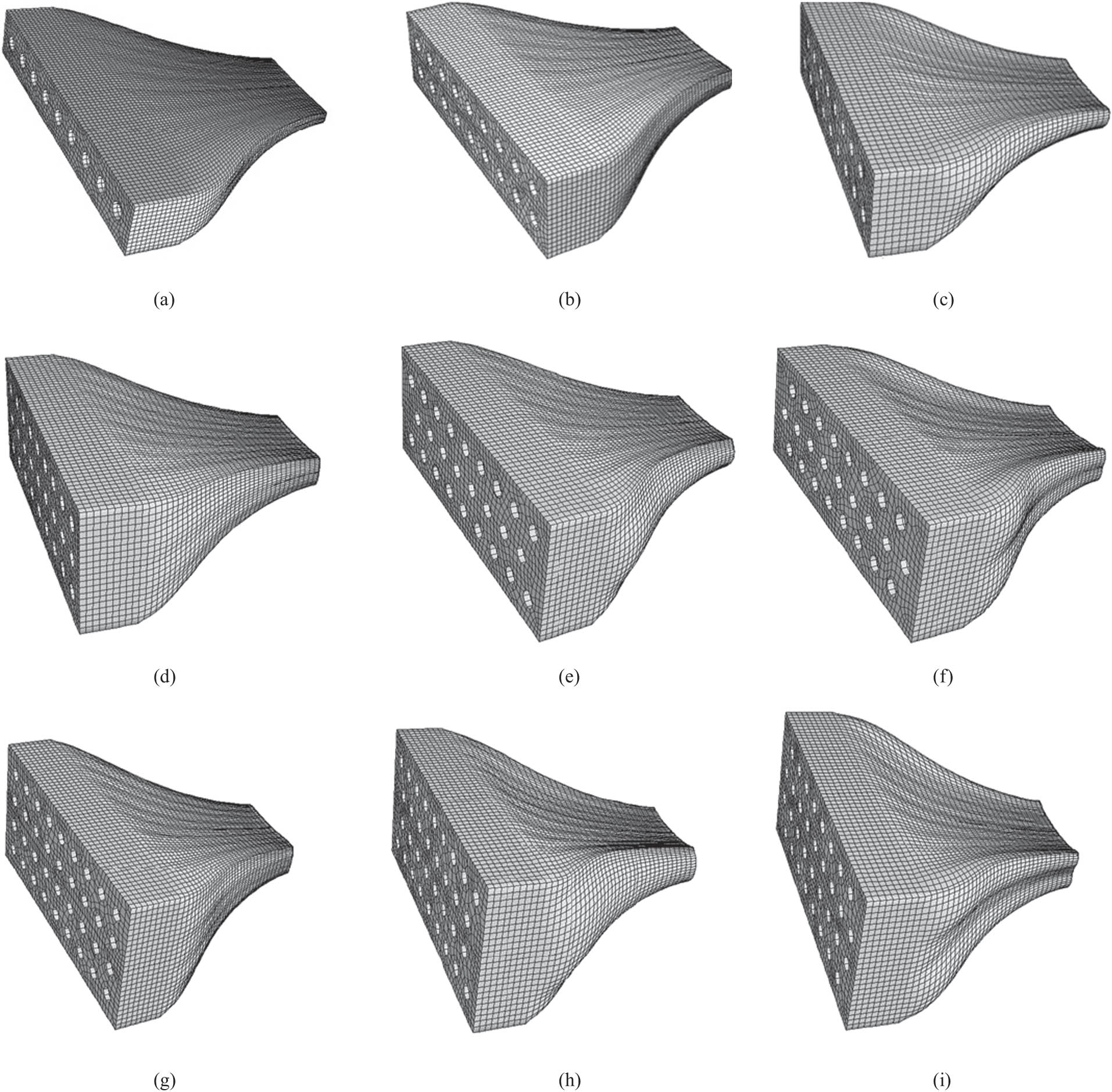
The shape of the multi-layer MCF in the extrusion die and outside the die. (a) Single-layer MCF with 9 capillaries. (b) Bi-layer MCF with 18 capillaries. (c) Bi-layer MCF with 17 capillaries. (d) Three-layer MCF with 27 capillaries. (e) Three-layer MCF with 26 capillaries. (f) Three-layer MCF with 25 capillaries. (g) Four-layer MCF with 36 capillaries. (h) Four-layer MCF with 16 capillaries in the middle. (i) Four-layer MCF with 18 capillaries in the middle.
From the numerical simulation results, every model is obviously divided into two subdomains, one is inside of the die and the other is outside of the die. At the end of the MCF, a stretch force is exerted. Under the action of normal force, the shape and the size of the MCF have been changed.
The upper and lower surfaces of the MCF inside the die are both flat, while the upper and lower surfaces outside the die are waved. This is because the die-swell effect of the polymer makes the surface of the MCF film contract and expand in different parts. As shown in Figure 5a, b, d, and g, the hollow capillary arrays are aligned. The upper and lower surfaces of the MCF are slightly waved. As shown in Figure 5c, e, f, h, and i, the hollow capillary arrays are non-aligned. The end of the upper and lower surfaces has obviously warpage deformation, especially as shown in Figure 5f, h, and i.
The sides of the MCF film are also not flat. As shown in Figure 5a, b, d, and g, they are slightly wavy. However, as shown in Figure 5c, e, and h, they are obviously swelled, while, in Figure 5f and i, they are obviously sunk. From the whole modeling, including the upper and side surfaces, the shape of the multi-layer MCF with hollow capillaries and aligned arrangement will be closer to the shape of the extrusion die. While the shapes of the multi-layer MCF with hollow capillaries and non-aligned arrangement are seriously deformed. Therefore, the hollow capillary array has a great effect on the shape of the multi-layer MCF.
3.1.2 Film size
The width and thickness of the single and multi-layer MCF were smaller under the effect of a 3 N stretching force. Detailed data are shown in Table 2.
Size shrinkage of the width and thickness in the multi-layer MCF under a stretch force of 3 N
| Model | Width | Thickness | A die | A film | A film/A die | ||||
|---|---|---|---|---|---|---|---|---|---|
| Die size (mm) | Film size (mm) | Shrinkage (%) | Die size (mm) | Film size (mm) | Shrinkage (%) | ||||
| 1 | 9.50 | 3.22 | 66 | 1.50 | 0.40 | 73 | 6.33 | 8.05 | 1.27 |
| 2 | 9.50 | 3.22 | 66 | 2.50 | 0.66 | 74 | 3.80 | 4.88 | 1.28 |
| 3 | 9.50 | 3.37 | 65 | 2.50 | 0.75 | 70 | 3.80 | 4.49 | 1.18 |
| 4 | 9.50 | 3.16 | 67 | 3.50 | 0.91 | 74 | 2.71 | 3.47 | 1.28 |
| 5 | 9.50 | 3.34 | 65 | 3.50 | 0.99 | 72 | 2.71 | 3.37 | 1.24 |
| 6 | 9.50 | 3.75 | 66 | 3.50 | 1.12 | 68 | 2.71 | 3.35 | 1.23 |
| 7 | 9.50 | 3.11 | 67 | 4.50 | 1.19 | 74 | 2.11 | 2.61 | 1.24 |
| 8 | 9.50 | 3.36 | 65 | 4.50 | 1.30 | 71 | 2.11 | 2.58 | 1.22 |
| 0 | 9.50 | 3.38 | 64 | 4.50 | 1.37 | 70 | 2.11 | 2.46 | 1.17 |
Table 2 shows the width and thickness of the die size and film size in the nine types of MCF models under a stretch force of 3 N. In the nine models, from one to four layers, the shrinkage of the width increases from 64% to 67%, and the shrinkage of the thickness increases from 68% to 74%. In the same layer models, more capillaries have higher shrinkage in size. In models h and i, the polymer content is the same but the shrinkage is different. It is because the warpage deformation caused by the polymer swell leads to a change in the film shape and film size.
The aspect ratio of the MCF die (A die) is the width to thickness of the MCF extrusion die in Eq. 2. Similarly, the aspect ratio of the MCF film (A film) is the width to thickness of the extrudate film in Eq. 3. A die and A film are the profile parameters of the multi-layer MCF before and after stretching in this study:
A die is a constant value in the nine types of models of the extrusion die. However, as shown in Figure 6c, the A film value is not the same in the nine types of models because the polymer swell and porosity are different in these nine models. A film/A die is the ratio of the width to thickness of the MCF before and after stretching. Figure 6c shows that A film/A die changes from 1.17 to 1.28 in the nine models. All A film/A die values are greater than 1, because of the application of a stretch force at the end of the films, and the A film/A die values are higher when the two-dimensional hollow capillaries are arranged regularly and orderly.
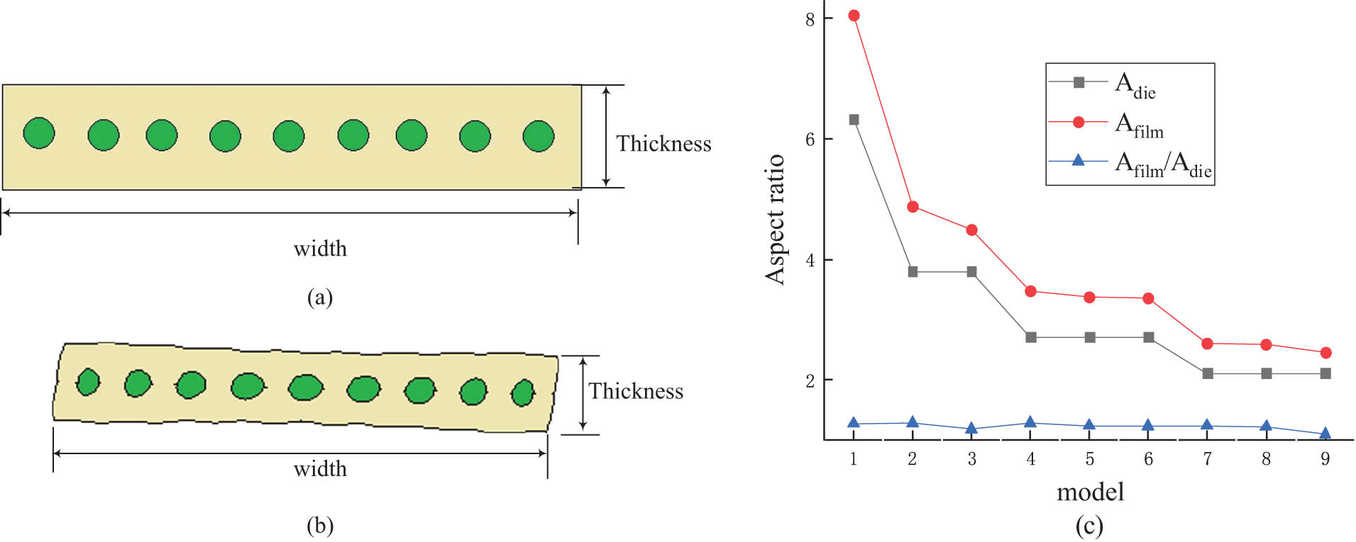
A die and A film in nine MCF models. The size of the (a) extrusion die and (b) MCF film and (c) A die and A film, and A film/A die.
3.2 Capillary shape and size
Under the action of a tensile force, the shape and size of the MCF and capillaries are changed. The inter-capillary aspect ratio is of the width to depth and A
capillary is greater than or equal to 1.
3.2.1 Single-layer MCF
As shown in Figure 7a, the shape of the external film and the internal capillary in a single-layer MCF are changed after stretching. In the extrusion die (before stretching), the internal capillary is all circle. The model is meshed by a triangle grid and uses the nonlinear densification technology. After the melt leaves the die, the film becomes thin and narrow under the action of a stretch force, and the internal capillary shapes are no longer circular. The inter-capillary aspect ratios are shown in Figure 7b. The internal aspect ratios of the capillaries located on both sides of the MCF film are nearly 1, i.e., the deformation of the capillaries is small. The internal aspect ratio of the capillary in the central is the largest.
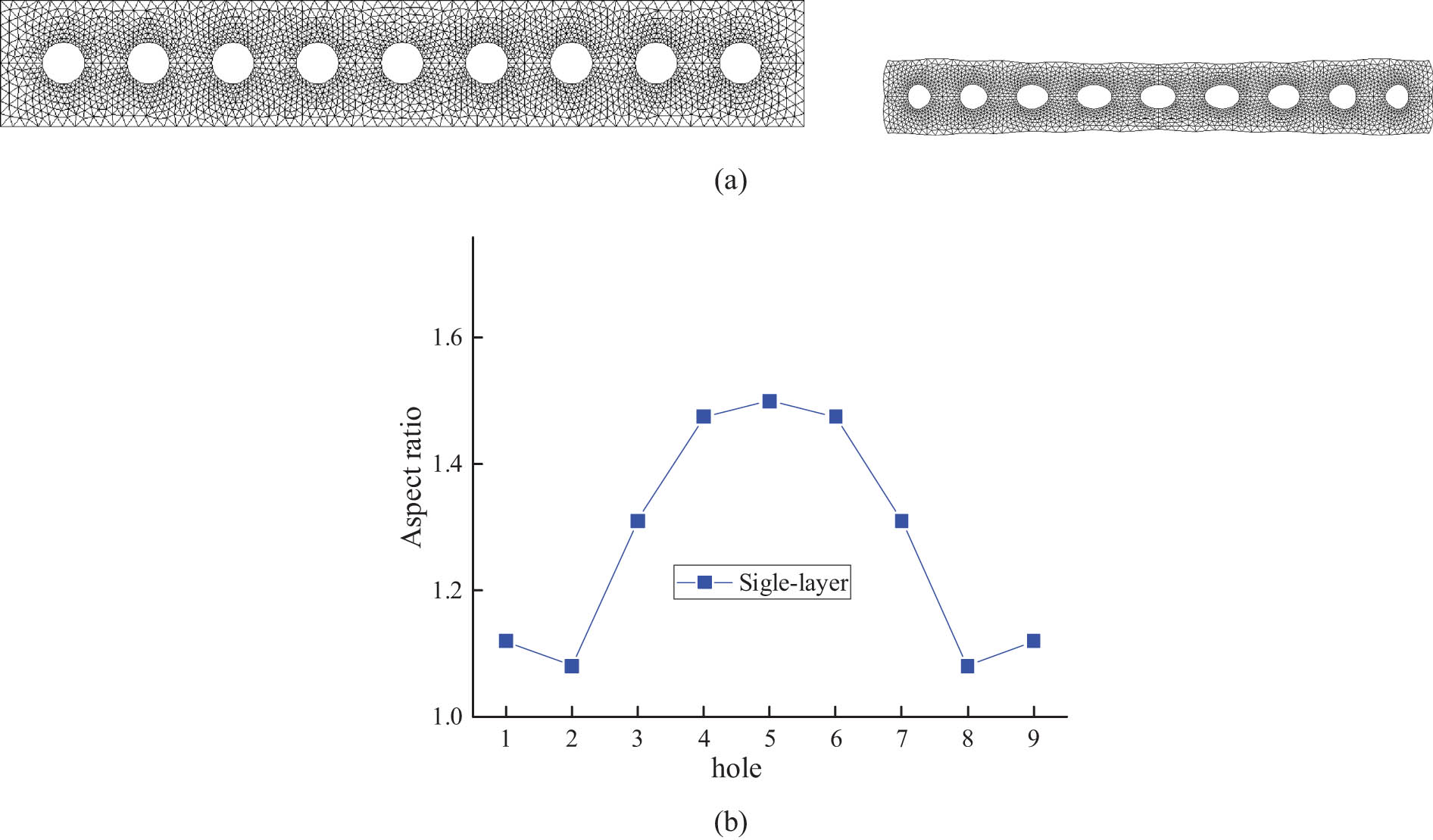
The cross section of a single-layer MCF before and after stretching, and aspect ratios of all holes. (a) Single-layer MCF with nine holes before and after stretching. (b) Inter-capillary aspect ratios of the single-layer MCF.
3.2.2 Bi-layer MCF
As shown in Figure 8, the shape and size of the external film and internal capillary in the bi-layer MCF with 18 or 17 capillaries have changed after stretching. After the polymer melt leaves the die, the film becomes thin and narrow under the action of a stretch force; its four surfaces (including upper, down, left, and right) are no longer flat and the capillary shapes are no longer circular. As shown in Figure 8b, on the upper left and upper right, there are two corners with an obvious swell because of the viscoelasticity of the polymer.
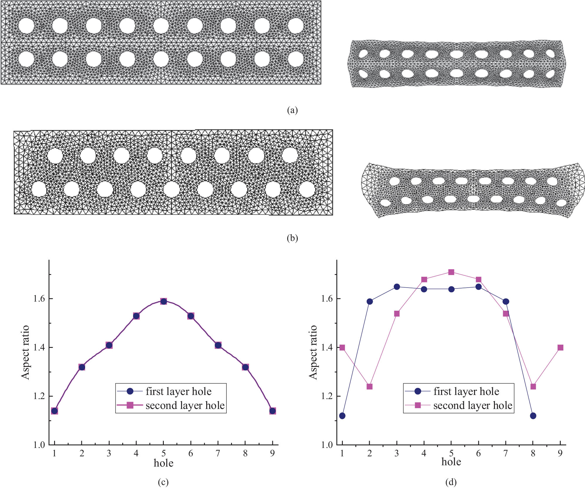
The cross section of the bi-layer MCF before and after stretching and the aspect ratios of all holes. (a) The bi-layer MCF with 18 holes before and after stretching. (b) Bi-layer MCF with 17 holes before and after stretching. Inter-capillary aspect ratios of the single-layer MCF with (c) 18 holes and (d) 17 holes.
The inter-capillary aspect ratio of the bi-layer MCF is shown in Figure 8c and d. The inter-capillary aspect ratio in the bi-layer MCF with 17 holes is higher than that in the bi-layer MCF with 18 holes and the aspect ratio of 11 capillaries is stable near 1.6. This shows that the two-dimensional hollow capillary array has a great effect on all hole shapes.
In the bi-layer MCF with 18 capillaries, the inter-capillary aspect ratio in the first layer is the same as in the second layer. In the same layer, the inter-capillary aspect ratio is higher in the central and lower on the two sides. From the central to the side, the aspect ratio decreases. But in the bi-layer MCF with 17 capillaries, the first layer has 8 holes, and the second layer has 9 holes. So, the inter-capillary aspect ratio in the first layer is different from the second layer.
3.2.3 Three-layer MCF
The cross section of the three-layer MCF before and after stretching and the inter-capillary aspect ratio of all holes are shown in Figure 9.
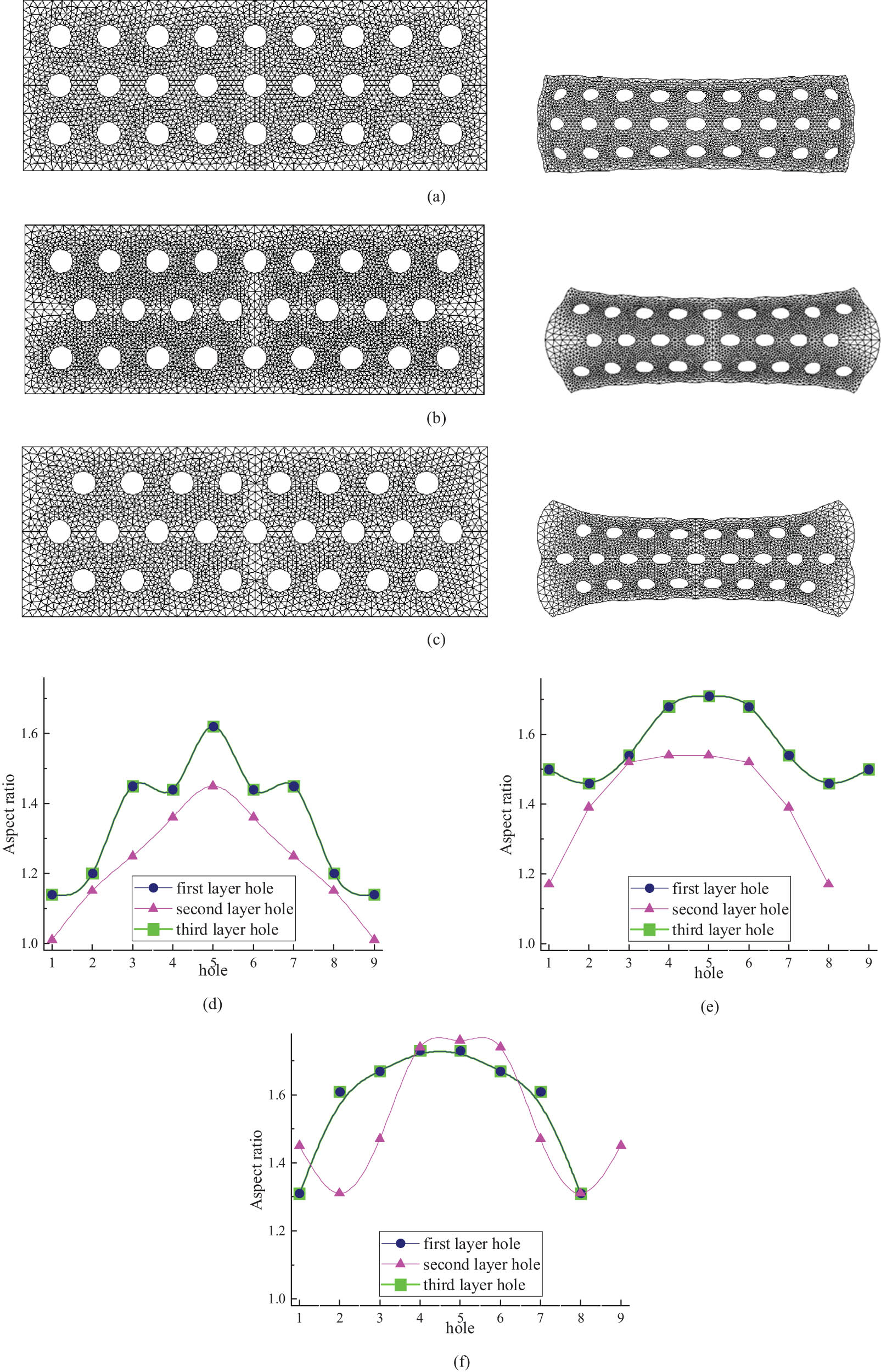
The cross section of the three-layer MCF before and after stretching, and the aspect ratios of all holes. (a) Three-layer MCF with 27 holes before and after stretching. (b) Three-layer MCF with 26 holes before and after stretching. (c) Three-layer MCF with 25 holes before and after stretching. Aspect ratios of the internal capillaries with (d) 27 holes, (e) 26 holes, and (f) 25 holes.
As shown in Figure 9, all the surfaces (upper, down, left, and right) in the three-layer MCF are not flat: in Figure 9b, it looks like a drum, and in Figure 9c, it looks like a dog bone shape. This shows that the two-dimensional hollow capillary array has a great effect on the film shape and film size.
The aspect ratios of the internal capillaries are shown in Figure 9d–f. The inter-capillary aspect ratios in the three-layer MCF with 26 and 25 capillaries are higher than that of the three-layer MCF with 27 capillaries.
In the three-layer MCF with 25, 26, and 27 capillaries, the inter-capillary aspect ratio in the first layer is the same as the third layer but higher than the middle layer. The aspect ratio is higher in the central and lower on the two sides in all layers. In the three-layer MCF with 25 capillaries, the inter-capillary aspect ratio values with capillaries are higher than 1.6; in the three-layer MCF with 26 capillaries, the inter-capillary aspect ratio values with 6 capillaries are higher than 1.6; and in three-layer MCF with 27 capillaries, the inter-capillary aspect ratio with only 2 capillaries is higher than 1.6. The highest value of A capillary is 1.76, it appears in the 25-capillary film. The lowest value of A capillary is 1.01, and it appears in the 27-capillary film.
3.2.4 Four-layer MCF
The cross sections of the four-layer MCF before and after stretching are shown in Figure 10. As shown in Figure 10b, it looks like a drum, and in Figure 10c it looks like a dog bone. The inter-capillary aspect ratios are also shown in Figure 10d–f. The inter-capillary aspect ratios in the four-layer MCF with 16 and 18 capillaries in the middle are higher than that of the four-layer MCF with 36 capillaries.
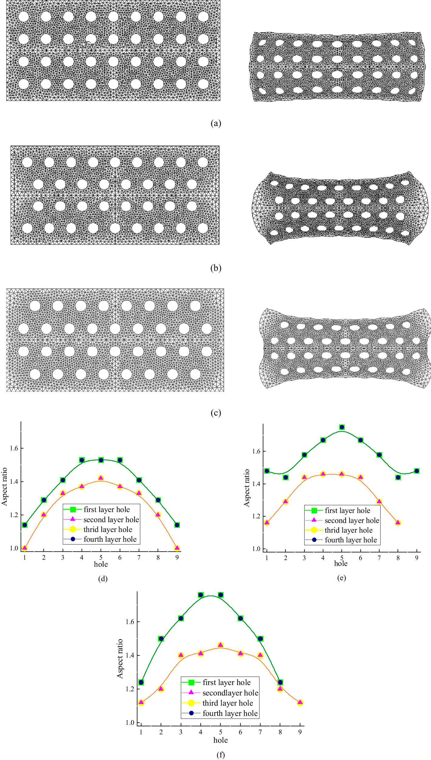
The cross section of the four-layer MCF before and after stretching, and the aspect ratios of all holes. (a) Four-layer MCF with 36 holes before and after stretching. Four-layer MCF with 34 holes before and after stretching, and the numbers of holes in middle layers are (b)16 holes, (c) 18 holes. Aspect ratios of the internal capillaries with (d) 36 holes, (e) 34 holes (16 holes in the middle), and (f) 34 holes (18 holes in the middle).
In the four-layer MCF, the inter-capillary aspect ratios in the first layer are the same as in the fourth layer, and the inter-capillary aspect ratios in the second layer are the same as in the third layer. The inter-capillary aspect ratios are bigger in the first and fourth layers but lower in the second and third layers. In the four-layer MCF with 16 capillaries in the middle, the inter-capillary aspect ratios with about 10 holes are higher than 1.6. In the four-layer MCF with 18 capillaries in the middle, the aspect ratio values with about 8 holes are higher than 1.6. In the four-layer MCF with 36 capillaries, no aspect ratio values are higher than 1.6.
3.3 Effects of two-dimensional hollow capillary array on the flow efficiency of the MCF
The geometric models of the multi-layer MCF belong to the bi-axial symmetric geometric model. In order to avoid data duplication, a 1/4 geometric model is taken to investigate the influence of the capillary arrays on the effect of the multi-layer MCF. The results are shown in Table 3.
Relationship between the capillary arrays and the average of A capillary and porosity in the multi-layer MCF
| Model | Capillary array | Hole layer | Aspect ratios of internal capillaries | Porosity film (%) | |||||||
|---|---|---|---|---|---|---|---|---|---|---|---|
| 1 | 2 | 3 | 4 | 5 | Average | P f1 | P f2 | Average | |||
| 1 | Aligned | 1 | 1.12 | 1.08 | 1.31 | 1.48 | 1.50 | 1.30 | 13.6 | 13.4 | 13.5 |
| 2 | Aligned | 1 | 1.14 | 1.32 | 1.41 | 1.53 | 1.59 | 1.40 | 16.1 | 15.7 | 15.9 |
| 3 | Non-aligned | 1 | 1.40 | 1.24 | 1.51 | 1.68 | 1.71 | 1.50 | 13.8 | 13.3 | 13.6 |
| 2 | 1.12 | 1.59 | 1.65 | 1.64 | — | ||||||
| 4 | Aligned | 1 | 1.14 | 1.20 | 1.45 | 1.44 | 1.62 | 1.34 | 18.4 | 17.2 | 17.8 |
| 2 | 1.01 | 1.50 | 1.25 | 1.36 | 1.45 | ||||||
| 5 | Non-aligned | 1 | 1.50 | 1.46 | 1.54 | 1.68 | 1.71 | 1.49 | 16.1 | 15.5 | 15.8 |
| 2 | 1.17 | 1.39 | 1.52 | 1.54 | — | ||||||
| 6 | Non-aligned | 1 | 1.31 | 1.61 | 1.67 | 1.73 | — | 1.56 | 15.6 | 14.4 | 15.0 |
| 2 | 1.45 | 1.31 | 1.47 | 1.74 | 1.76 | ||||||
| 7 | Aligned | 1 | 1.14 | 1.29 | 1.41 | 1.53 | 1.53 | 1.32 | 18.3 | 18.0 | 18.2 |
| 2 | 1.00 | 1.20 | 1.33 | 1.37 | 1.42 | ||||||
| 8 | Non-aligned | 1 | 1.48 | 1.44 | 1.58 | 1.67 | 1.75 | 1.46 | 16.5 | 16.0 | 16.3 |
| 2 | 1.16 | 1.29 | 1.44 | 1.46 | — | ||||||
| 9 | Non-aligned | 1 | 1.24 | 1.50 | 1.62 | 1.76 | — | 1.43 | 16.6 | 16.2 | 16.4 |
| 2 | 1.12 | 1.20 | 1.40 | 1.41 | 1.46 | ||||||
Every capillary is elliptical in shape or oval. As a result, an equivalent radius, R eq (20), was calculated from Eq. 4 and used to indicate the actual capillary radius. In Eq. 4, a and b are the major and minor semi-axes of the ellipse, respectively. N is the number of the holes. The area of all the elliptical holes can be calculated by Eqs. 5 and 6. A cs is the cross-sectional area of the MCF film, which is calculated with the Ansys software. The porosity of the film is the ratio of all the elliptical hole areas to the whole cross-sectional area (Eqs. 7 and 8):
As shown in Table 3, the aspect ratios of the internal capillaries range from 1.01 to 1.76. The porosity of the film ranges from 13.5% to 18.2%. Under the conditions of the same layer, when the capillary array is aligned, the porosity of the MCF is high and the capillary aspect ratio is small. When the capillary array is non-aligned, the porosity of the MCF is small and the aspect ratio of the capillary is relatively higher.
The flow efficiency of the multi-layer MCF depends on two factors: flow resistance and specific surface area. When the aspect ratio of the capillaries is close to 1, the shape is close to circular, and the flow resistance is the minimum under the same volume flow rate. When the aspect ratio of the capillaries is far away from 1, the specific surface area is the maximum under the same volume, and the heat exchange is also the maximum. If the multi-layer MCF is used for fluid transportation, such as the micro melt pump and microreactor, the multi-layer MCF with aligned capillary arrays should be chosen. It is very beneficial for reducing fluid resistance and improving fluid transmission efficiency. If the multi-layer MCF is used for exchange energy, such as a micro heat exchanger, the multi-layer MCF with a non-aligned capillary array should be chosen.
The function of the multi-layer MCF depends on two important parameters: the film porosity and the capillary aspect ratio. The aligned four-layer MCF film has the highest film porosity and the smallest capillary aspect ratio in the multi-layer MCF. It is very beneficial for reducing fluid resistance and improving fluid transmission efficiency. So, the aligned four-layer MCF film is suitable for use for fluid transportation, such as micro melt pumps and microreactors. In order to improve the efficiency of microheat exchangers, MCF should have higher film porosity and a higher capillary aspect ratio. In multi-layer MCF films, non-aligned MCFs have a higher capillary aspect ratio than their arranged MCFs. The three/four-layered MCF film arranged in a non-aligned manner has higher film porosity than the two-layer MCF. It is best to choose three/four-layer MCF films arranged in a non-aligned manner for energy exchange, such as micro heat exchangers (Figure 11).
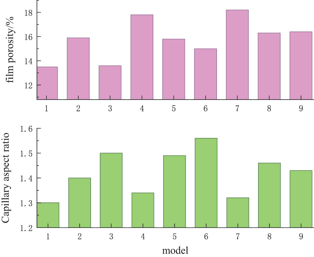
Film porosity and capillary aspect ratio in the nine models.
4 Conclusions
Under the conditions of the inlet flow rate Q = 5 cm3·s−1 and the tensile force is 3 N, the influence of the hollow capillary array on the shape and size of the whole multi-layer MCF is studied through numerical simulation.
After the MCF separates from the extrusion die, the shape of the capillary changes from circular to elliptical or oval. The central capillaries have a large ratio of width to depth, and the edge capillaries have a small ratio of width to depth. The aspect ratios of capillary change from 1.01 to 1.76.
With the same layers, when the two-dimensional hollow capillary array is aligned, the multi-layer MCF has a small aspect ratio of capillary and large film porosity. When the two-dimensional hollow capillary array is non-aligned, the MCF has a large aspect ratio of capillary and small film porosity.
In the four-layer MCF, if the capillary array is aligned, the aspect ratio of the capillaries is lower and the film porosity is higher. They are suitable for micro-reactors and melt pumps. In the three- and four-layer MCF, if the capillary arrays are non-aligned, the high aspect ratio of capillaries and higher film porosity will be obtained. Therefore, they are suitable for micro heat exchangers.
-
Funding information: This work was supported by the National Natural Science Foundation of China (NSFC) (No. 52063021). Grant Recipient: Jianhua Xiao.
-
Author contributions: Jianhua Xiao: writing – review and editing, supervision; Ru Yang: writing- original draft preparation, project administration; Shiqiang Song: conceptualization, methodology; Haibin Wang and Haiwei Wen: software, investigation.
-
Conflict of interest: The authors state no conflict of interest.
Reference
(1) Hallmark B, Hesketh RP, Hornung C, Mackley MR. The manufacture and hydraulic characterization of novel micro-capillary film (MCF) extrusions. Proceedings of the 1st International Symposium on Process Intensification and Miniaturization; 2003 Jan 22–24. UK: Newcastle; 2003.Search in Google Scholar
(2) Hallmark B, Mackley MR. The effect of polymer rheology and processing conditions on the manufacture of novel micro-capillary film (MCF) extrusions. Proceedings of the XIVth International Congress on Rheology; 2004 Aug 22–27. Seoul, Korea. Seoul: The Korean Society of Rheology; 2004.Search in Google Scholar
(3) Gerald B, David M, Joseph D, Tom P, Clifford T. Microcapillary film membranes based on polyvinylidene fluoride. ANTEC Conference; 2018 May 12–15. USA: Hilton Anaheim; 2018. https://www.researchgate.net/publication/325575762.Search in Google Scholar
(4) Hallmark B, Mackley MR, Gadala-Maria F. Hollow microcapillary arrays in thin plastic films. Adv Eng Mater. 2005;7(6):545–7. 10.1002/adem.200400154.Search in Google Scholar
(5) Hornung CH, Hallmark B, Hesketh RP, Mackley MR. The fluid flow and heat transfer performance of thermoplastic microcapillary films. J Micromech Microeng. 2006;16(2):434–47. 10.1088/0960-1317/16/2/030.Search in Google Scholar
(6) Hallmark B, Hornung CH, Broady D, Price-Kuehne C, Mackley MR. The application of plastic microcapillary films for fast transient micro-heat exchange. Int J Heat Mass Transf. 2008;51(21–22):5344–58. 10.1016/j.ijheatmasstransfer.2008.01.036.Search in Google Scholar
(7) Dorfling C, Hornung CH, Hallmark B, Beaumont RJJ, Fovargue H, Mackley MR. The experimental response and modelling of a solar heat collector fabricated from plastic microcapillary films. Sol Energy Mat Sol Cells. 2010;94(07):1207–21. 10.1016/j.solmat.2010.03.008.Search in Google Scholar
(8) Hornung CH, Mackley MR, Baxendale IR, Ley SV. A microcapillary flow disc reactor for organic synthesis. Org Process Res Dev. 2007;11(3):399–405. 10.1021/op700015f.Search in Google Scholar
(9) Gill KK, Gibson R, Yiu KHC, Hester P. Microcapillary film reactor outperforms single-bore mesocapillary reactors in continuous flow chemical reactions. CEJ. 2021;408(15):127860–71. 10.1016/j.cej.2020.127860.Search in Google Scholar
(10) Barbosa AI, Barreto AS, Reis NM. Transparent, hydrophobic FEP Teflon offers rapid, robust and irreversible passive adsorption of diagnostic antibodies for sensitive optical biosensing. ACS Applied Bio Materials. 2019;2(7):2780–90. 10.1021/acsabm.9b00214.Search in Google Scholar PubMed
(11) Moreira RPM, Puma GL. CFD modeling of pharmaceuticals and CECs removal by UV/H2O2 process in helical microcapillary photoreactors and evaluation of OH radical rate constants. CEJ. 2021;415(07):128833–47. 10.1016/j.cej.2021.128833.Search in Google Scholar
(12) Nicholas JD, Bart H, Pulkit A, James T, Vincent BH, Nigel KHS. On the magnetic field architecture required to capture superparamagnetic nanoparticles in a microcapillary flow. J Nanopart Res. 2010;12:307–17. 10.1007/s11051-009-9615-0.Search in Google Scholar
(13) Marcus B, Ian RB, Steven VL. The flow synthesis of heterocycles for natural product and medicinal chemistry applications. Mol Divers. 2011;15:613–30. 10.1007/s11030-010-9282-1.Search in Google Scholar PubMed
(14) Isabel PA, Nuno MR. Immunocapture of Escherichia coli in a fluoropolymer microcapillary array. J Chromatogr A. 2019;1585(25):46–55. 10.1016/j.chroma.2018.11.067.Search in Google Scholar PubMed
(15) Zheyun X, Feng J, Fanghao Z, Zhongbin X, Haoyan X, Xiaodong R. Determination of hydrogen peroxide using novel test strips based on plastic microcapillary film. Anal Methods-UK. 2017;21:3230–6. 10.1039/C7AY00584A.Search in Google Scholar
(16) Liu J, Xu Z, Shan Y, Huang X. Applications of microcapillary film in bioanalytical techniques. Analyst. 2021;5(01):1529–37. 10.1039/D0AN01945C.Search in Google Scholar PubMed
(17) Alves IP, Reis NM. Microfluidic smartphone quantitation of Escherichia coli in synthetic urine. Biosens Bioelectron. 2019;145(09):111624–32. 10.1016/j.bios.2019.111624.Search in Google Scholar PubMed
(18) Medina DI, Chinesta F, Mackley MR. Heat melding of voided polyethylene microstructures. Polymer. 2009;50(14):3302–10. 10.1016/j.polymer.2009.04.051.Search in Google Scholar
(19) Hallmark B, Gadala-Maria F, Mackley MR. The melt processing of polymer microcapillary film (MCF). J Non-Newton Fluid. 2005;128(3):83–98. 10.1016/j.jnnfm.2005.03.013.Search in Google Scholar
(20) Lamb H. Hydrodynamics. 6th edn. New York: Dover; 1945.Search in Google Scholar
© 2023 the author(s), published by De Gruyter
This work is licensed under the Creative Commons Attribution 4.0 International License.
Articles in the same Issue
- Research Articles
- Chitosan nanocomposite film incorporating Nigella sativa oil, Azadirachta indica leaves’ extract, and silver nanoparticles
- Effect of Zr-doped CaCu3Ti3.95Zr0.05O12 ceramic on the microstructure, dielectric properties, and electric field distribution of the LDPE composites
- Effects of dry heating, acetylation, and acid pre-treatments on modification of potato starch with octenyl succinic anhydride (OSA)
- Loading conditions impact on the compression fatigue behavior of filled styrene butadiene rubber
- Characterization and compatibility of bio-based PA56/PET
- Study on the aging of three typical rubber materials under high- and low-temperature cyclic environment
- Numerical simulation and experimental research of electrospun polyacrylonitrile Taylor cone based on multiphysics coupling
- Experimental investigation of properties and aging behavior of pineapple and sisal leaf hybrid fiber-reinforced polymer composites
- Influence of temperature distribution on the foaming quality of foamed polypropylene composites
- Enzyme-catalyzed synthesis of 4-methylcatechol oligomer and preliminary evaluations as stabilizing agent in polypropylene
- Molecular dynamics simulation of the effect of the thermal and mechanical properties of addition liquid silicone rubber modified by carbon nanotubes with different radii
- Incorporation of poly(3-acrylamidopropyl trimethylammonium chloride-co-acrylic acid) branches for good sizing properties and easy desizing from sized cotton warps
- Effect of matrix composition on properties of polyamide 66/polyamide 6I-6T composites with high content of continuous glass fiber for optimizing surface performance
- Preparation and properties of epoxy-modified thermosetting phenolic fiber
- Thermal decomposition reaction kinetics and storage life prediction of polyacrylate pressure-sensitive adhesive
- Effect of different proportions of CNTs/Fe3O4 hybrid filler on the morphological, electrical and electromagnetic interference shielding properties of poly(lactic acid) nanocomposites
- Doping silver nanoparticles into reverse osmosis membranes for antibacterial properties
- Melt-blended PLA/curcumin-cross-linked polyurethane film for enhanced UV-shielding ability
- The affinity of bentonite and WO3 nanoparticles toward epoxy resin polymer for radiation shielding
- Prolonged action fertilizer encapsulated by CMC/humic acid
- Preparation and experimental estimation of radiation shielding properties of novel epoxy reinforced with Sb2O3 and PbO
- Fabrication of polylactic acid nanofibrous yarns for piezoelectric fabrics
- Copper phenyl phosphonate for epoxy resin and cyanate ester copolymer with improved flame retardancy and thermal properties
- Synergistic effect of thermal oxygen and UV aging on natural rubber
- Effect of zinc oxide suspension on the overall filler content of the PLA/ZnO composites and cPLA/ZnO composites
- The role of natural hybrid nanobentonite/nanocellulose in enhancing the water resistance properties of the biodegradable thermoplastic starch
- Performance optimization of geopolymer mortar blending in nano-SiO2 and PVA fiber based on set pair analysis
- Preparation of (La + Nb)-co-doped TiO2 and its polyvinylidene difluoride composites with high dielectric constants
- Effect of matrix composition on the performance of calcium carbonate filled poly(lactic acid)/poly(butylene adipate-co-terephthalate) composites
- Low-temperature self-healing polyurethane adhesives via dual synergetic crosslinking strategy
- Leucaena leucocephala oil-based poly malate-amide nanocomposite coating material for anticorrosive applications
- Preparation and properties of modified ammonium polyphosphate synergistic with tris(2-hydroxyethyl) isocynurate for flame-retardant LDPE
- Thermal response of double network hydrogels with varied composition
- The effect of coated calcium carbonate using stearic acid on the recovered carbon black masterbatch in low-density polyethylene composites
- Investigation of MXene-modified agar/polyurethane hydrogel elastomeric repair materials with tunable water absorption
- Damping performance analysis of carbon black/lead magnesium niobite/epoxy resin composites
- Molecular dynamics simulations of dihydroxylammonium 5,5′-bistetrazole-1,1′-diolate (TKX-50) and TKX-50-based PBXs with four energetic binders
- Preparation and characterization of sisal fibre reinforced sodium alginate gum composites for non-structural engineering applications
- Study on by-products synthesis of powder coating polyester resin catalyzed by organotin
- Ab initio molecular dynamics of insulating paper: Mechanism of insulating paper cellobiose cracking at transient high temperature
- Effect of different tin neodecanoate and calcium–zinc heat stabilizers on the thermal stability of PVC
- High-strength polyvinyl alcohol-based hydrogel by vermiculite and lignocellulosic nanofibrils for electronic sensing
- Impacts of micro-size PbO on the gamma-ray shielding performance of polyepoxide resin
- Influence of the molecular structure of phenylamine antioxidants on anti-migration and anti-aging behavior of high-performance nitrile rubber composites
- Fiber-reinforced polyvinyl alcohol hydrogel via in situ fiber formation
- Preparation and performance of homogenous braids-reinforced poly (p-phenylene terephthamide) hollow fiber membranes
- Synthesis of cadmium(ii) ion-imprinted composite membrane with a pyridine functional monomer and characterization of its adsorption performance
- Impact of WO3 and BaO nanoparticles on the radiation shielding characteristics of polydimethylsiloxane composites
- Comprehensive study of the radiation shielding feature of polyester polymers impregnated with iron filings
- Preparation and characterization of polymeric cross-linked hydrogel patch for topical delivery of gentamicin
- Mechanical properties of rCB-pigment masterbatch in rLDPE: The effect of processing aids and water absorption test
- Pineapple fruit residue-based nanofibre composites: Preparation and characterizations
- Effect of natural Indocalamus leaf addition on the mechanical properties of epoxy and epoxy-carbon fiber composites
- Utilization of biosilica for energy-saving tire compounds: Enhancing performance and efficiency
- Effect of capillary arrays on the profile of multi-layer micro-capillary films
- A numerical study on thermal bonding with preheating technique for polypropylene microfluidic device
- Development of modified h-BN/UPE resin for insulation varnish applications
- High strength, anti-static, thermal conductive glass fiber/epoxy composites for medical devices: A strategy of modifying fibers with functionalized carbon nanotubes
- Effects of mechanical recycling on the properties of glass fiber–reinforced polyamide 66 composites in automotive components
- Bentonite/hydroxyethylcellulose as eco-dielectrics with potential utilization in energy storage
- Study on wall-slipping mechanism of nano-injection polymer under the constant temperature fields
- Synthesis of low-VOC unsaturated polyester coatings for electrical insulation
- Enhanced apoptotic activity of Pluronic F127 polymer-encapsulated chlorogenic acid nanoparticles through the PI3K/Akt/mTOR signaling pathway in liver cancer cells and in vivo toxicity studies in zebrafish
- Preparation and performance of silicone-modified 3D printing photosensitive materials
- A novel fabrication method of slippery lubricant-infused porous surface by thiol-ene click chemistry reaction for anti-fouling and anti-corrosion applications
- Development of polymeric IPN hydrogels by free radical polymerization technique for extended release of letrozole: Characterization and toxicity evaluation
- Tribological characterization of sponge gourd outer skin fiber-reinforced epoxy composite with Tamarindus indica seed filler addition using the Box–Behnken method
- Stereocomplex PLLA–PBAT copolymer and its composites with multi-walled carbon nanotubes for electrostatic dissipative application
- Enhancing the therapeutic efficacy of Krestin–chitosan nanocomplex for cancer medication via activation of the mitochondrial intrinsic pathway
- Variation in tungsten(vi) oxide particle size for enhancing the radiation shielding ability of silicone rubber composites
- Damage accumulation and failure mechanism of glass/epoxy composite laminates subjected to repeated low velocity impacts
- Gamma-ray shielding analysis using the experimental measurements for copper(ii) sulfate-doped polyepoxide resins
- Numerical simulation into influence of airflow channel quantities on melt-blowing airflow field in processing of polymer fiber
- Cellulose acetate oleate-reinforced poly(butylene adipate-co-terephthalate) composite materials
- Radiation shielding capability and exposure buildup factor of cerium(iv) oxide-reinforced polyester resins
- Recyclable polytriazole resins with high performance based on Diels-Alder dynamic covalent crosslinking
- Adsorption and recovery of Cr(vi) from wastewater by Chitosan–Urushiol composite nanofiber membrane
- Comprehensive performance evaluation based on electromagnetic shielding properties of the weft-knitted fabrics made by stainless steel/cotton blended yarn
- Review Articles
- Preparation and application of natural protein polymer-based Pickering emulsions
- Wood-derived high-performance cellulose structural materials
- Flammability properties of polymers and polymer composites combined with ionic liquids
- Polymer-based nanocarriers for biomedical and environmental applications
- A review on semi-crystalline polymer bead foams from stirring autoclave: Processing and properties
- Rapid Communication
- Preparation and characterization of magnetic microgels with linear thermosensitivity over a wide temperature range
- Special Issue: Biodegradable and bio-based polymers: Green approaches (Guest Editors: Kumaran Subramanian, A. Wilson Santhosh Kumar, and Venkatajothi Ramarao)
- Synthesis and characterization of proton-conducting membranes based on bacterial cellulose and human nail keratin
- Fatigue behaviour of Kevlar/carbon/basalt fibre-reinforced SiC nanofiller particulate hybrid epoxy composite
- Effect of citric acid on thermal, phase morphological, and mechanical properties of poly(l-lactide)-b-poly(ethylene glycol)-b-poly(l-lactide)/thermoplastic starch blends
- Dose-dependent cytotoxicity against lung cancer cells via green synthesized ZnFe2O4/cellulose nanocomposites