Design and optimization of a modified straight-tapered Vivaldi antenna using ANN for GPR system
-
Mohammed K. Abbas
 ,
Ali J. Salim
,
Ali J. Salim

Abstract
Conventional methods for determining soil density compaction and moisture are often time-consuming, destructive, and rely heavily on laboratory analyses. Similarly, standard ground-penetrating radar (GPR) systems generate images that are difficult to interpret, lacking direct access to key parameters such as delay times and phase shifts. This study presents a modified straight-tapered Vivaldi antenna (STVA) for non-destructive soil compaction measurement. This tapered section of the traditional Vivaldi antenna is modified with a straight side instead of the traditional curved shape. The proposed antenna is designed and printed on an FR4 substrate with a dielectric constant of 4.3 and a thickness of 1.6 mm with dual-impedance bandwidths of 0.74–1.00 GHz (31%) and 2.2–2.85 GHz (26%). With the aid of the CST software program, the desired antenna is constructed and simulated, occupying a physical area of (100 × 115) mm2. The electrical size of the antenna is (0.266 × 0.306) λ 2. Consequently, the antenna achieves a gain of 2–6.5 dB and radiation efficiencies of 99 and 98.2% at the lower and upper bands, respectively. The experimental results demonstrate that the STVA antenna achieves a strong agreement between the measured and simulated reflection coefficients (S11). Using a vector network analyzer, the system directly extracts phase and delay parameters, eliminating the need for complex GPR image interpretation requirements. The measured data, processed through an artificial neural network, accurately predict soil compaction levels. As compaction increases, air-filled voids decrease, raising the soil’s effective dielectric constant (εᵣ), which in turn alters the signal’s phase and delay-providing a reliable indicator for compaction. This integrated approach outperforms conventional GPR techniques, offering real-time, accurate, and cost-effective soil characterization for geotechnical applications.
1 Introduction
Ground-penetrating radar (GPR) has become a widely accepted non-destructive technique for investigating subsurface soil structures over the past five decades. Among the suitable antennas utilized in GPR systems are Vivaldi antennas because they provide directional radiation patterns. This allows high-resolution reflections and deep penetration through various types of soil. Moreover, their directivity is highly appreciated due to ease of integration into systems and low cost, making them ideal for GPR applications [1,2]. However, there is a tradeoff when selecting frequencies for radar scanning – higher ones will result in better resolution but shallower penetration depths, while lower frequencies can give sufficient depth but at lower resolution [3,4].
Traditional soil density and moisture measurements require destructive sampling and time-consuming laboratory analysis that disrupts natural soil layers. While non-destructive GPR techniques have been explored as alternatives, conventional GPR systems produce complex qualitative images that lack direct access to critical quantitative parameters such as phase differences and delay times, essential for accurate soil moisture and compaction evaluation.
Several designs for ultra wide band (UWB) Vivaldi antennas have been suggested in the literature [6,7,8,9] using different approaches to improve the performance, such as high gain, low power, or multi-layer-based ones.
Zerrad et al. proposed the design of a slotted antipodal Vivaldi antenna for various (UWB) applications, including the Internet of Things (IoT). The goal is to maintain good performance across a wide range from 3.29 to 45 GHz for different advanced communication systems [5].
Jaiswal et al. proposed integrating metamaterials and defected ground planes in UWB antennas to increase gain. The proposed UWB antipodal Vivaldi antenna design involves a metasurface with notches that improve the gain and directivity without increasing its size [6].
Yuan et al. designed an all-frequency reconfigurable antenna operating in both single-pole and Vivaldi modes. This flexible device suits a variety of wireless situations, highlighting its usefulness in diverse communication environments. The study describes how this antenna is made, uses examples, and finally presents detailed information on how well it works when used with different types of wireless devices [7].
Guruswamy et al. presented a compact microwave imaging designed ultra wideband Vivaldi antenna featuring hemi-cylindrical slots and directors at its backside due to which this type of feeding structure enhanced directivity along with bandwidth, making it suitable for high-resolution imaging systems. The work comprises extensive simulations and experimental investigations that demonstrate the potential of the antenna as a future imaging modality [8].
Huang et al. [9] proposed a novel method to enhance the gain of antipodal Vivaldi antennas by introducing a V-shaped air slot in the antenna substrate. This technique improves performance without increasing the antenna size or requiring additional components. By modifying the effective permittivity along the radiating conductors, the electromagnetic waves are guided more efficiently within the central dielectric region, resulting in higher gain and better radiation characteristics.
Similarly, Babu et al. [10] developed a compact triband meander line-based antenna with an asymmetric CPW feed, operating at 5.3, 6.6, and 8.1 GHz, which achieved efficiency above 80% and a gain of 7.09 dB, demonstrating suitability for Wi-MAX, public safety, and satellite applications.
In another work, Jahan et al. [11] proposed a dual-band four-port MIMO circular ring plasmonic antenna that provided superior isolation, a low envelope correlation coefficient, and a peak gain of 7.6 dB at 4.3 and 6.1 GHz, confirming its effectiveness for modern wireless communication systems.
Likewise, Lavadiya et al. [12] designed a low-profile multiband frequency-reconfigurable patch antenna using PIN diodes, offering tunability across the S, C, X, and Ku bands with a maximum bandwidth of 1,100 MHz, 700 MHz tunability, and a minimum reflectance response of –28.22 dB, highlighting its application potential in the satellite, military, and sensing domains.
Traditionally, soil compaction (density) is measured by extracting samples for laboratory testing. This method, while widely used, is time-consuming, invasive, and often disrupts the soil’s natural layers. To overcome these limitations, non-destructive testing (NDT) techniques have been explored, with GPR being one of the most common methods. GPR generates subsurface images but typically provides qualitative data, making it challenging to extract critical parameters such as delay times and phase differences that are essential for accurately evaluating soil moisture and compaction.
Recent advancements in antenna design have addressed the increasing demand for efficient, compact, and dual-band structures suited for applications such as wireless sensor networks, the IoT, and International Telecommunication Union (ITU) standards. Saikumar et al. [13] developed a miniature MIMO antenna with patterned surface enhancements, achieving improved isolation and high radiation efficiency. Similarly, Kundu et al. [14] proposed a compact wideband trapezoidal-stepped patch antenna for dual-band operation with enhanced gain and bandwidth. Aras et al. [15] introduced a dual-resonant crescent-moon-shaped antenna using concentric circular rings, offering compact geometry and strong impedance matching.
Abbas et al. [16] proposed a high-efficiency, dual-moon-printed antenna using a triangle slot to enhance matching at 1.1 GHz, for measuring sand gradation.
More recently, Srinivas et al. [17] designed a slotted T-shaped patch antenna with CPW feed for IoT/ITU applications, achieving low return loss and high gains (up to 6.5 dBi) at 6.2 and 8.3 GHz.
In addition, a dual-band Vivaldi antenna with an electrical size of (0.424 × 0.429 × 0.013) λ 0, functioning in the dual bands of 2.6–3.46 and 4.16–5.35 GHz, was proposed by Chaabane and Guerroui. This antenna offers 1–3.8 dBi of gain, and its efficiency is in the region of 62–85%. This is a large-sized, high-frequency antenna [18].
These studies underscore the significance of innovative miniaturized and multiband antenna structures – principles that directly align with the goals of this work in developing a compact straight-tapered Vivaldi antenna (STVA) antenna for soil sensing.
This study used two identical antennas instead of a conventional single-antenna GPR setup. This approach allows for calculating the delay time and S21 parameters to assess the soil moisture content and density compaction. Signals transmitted through the soil are received by a second antenna connected to a vector network analyzer (VNA), enabling precise measurement and analysis.
The objectives of this study are to develop a compact STVA with dual-band operation suitable for in situ soil parameter sensing and to measure soil moisture and density compaction using a VNA, unlike traditional methods that rely on images captured by GPR. An artificial neural network (ANN) will be employed to map these parameters to accurately predict soil density and moisture, overcoming the limitations of conventional GPR techniques.
This article is structured as follows: Section 2 covers the STVA antenna design and analysis, Section 3 presents simulation results, Section 4 provides experimental validation, Section 5 describes the VNA-based soil sensing methodology and ANN implementation, Section 6 discusses performance analysis, and Section 7 concludes the work.
2 STVA
The methodology of the proposed STVA consists of three main phases: antenna design, antenna testing, and developing a model for soil compaction measurement.
2.1 Design and fabrication of an antenna
The substrate used is FR4 with relative permittivity equal to 4.3, a thickness of h = 1.6 mm, and loss tangent equal to 0.027. Figure 1 illustrates a rectangular substrate with side lengths La = 115 mm and Wa = 100 mm.
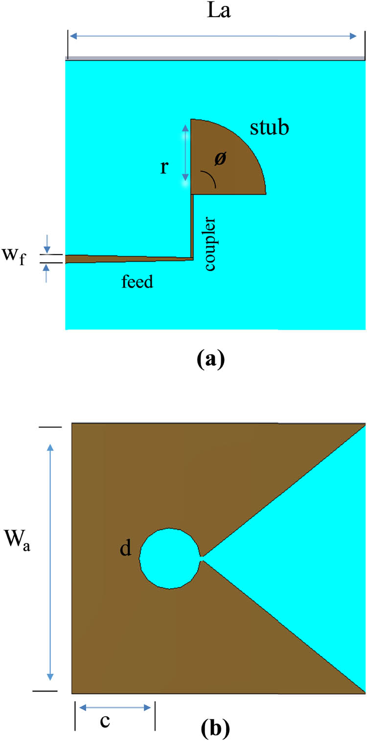
The proposed antenna: (a) front view and (b) back view.
The design of the proposed antenna involves optimization of the microstrip main feed line, coupler, and radial bowtie stub to radiate power in the triangular pattern over a symmetrical slot line. A feed width of 3.1 mm is selected to realize a reference impedance of Z 0 = 50 Ω for correct coupling with the SMA connector and the coaxial cable. The parametric analysis reveals how resonance can degrade when transitioning from curved to linear tapering, which complicates impedance matching in specific frequency bands, as illustrated in Figure 2. In the optimized configuration, the curved profile was replaced by a straight edge, and the circular slot was repositioned and resized, thereby yielding the improved performance observed.
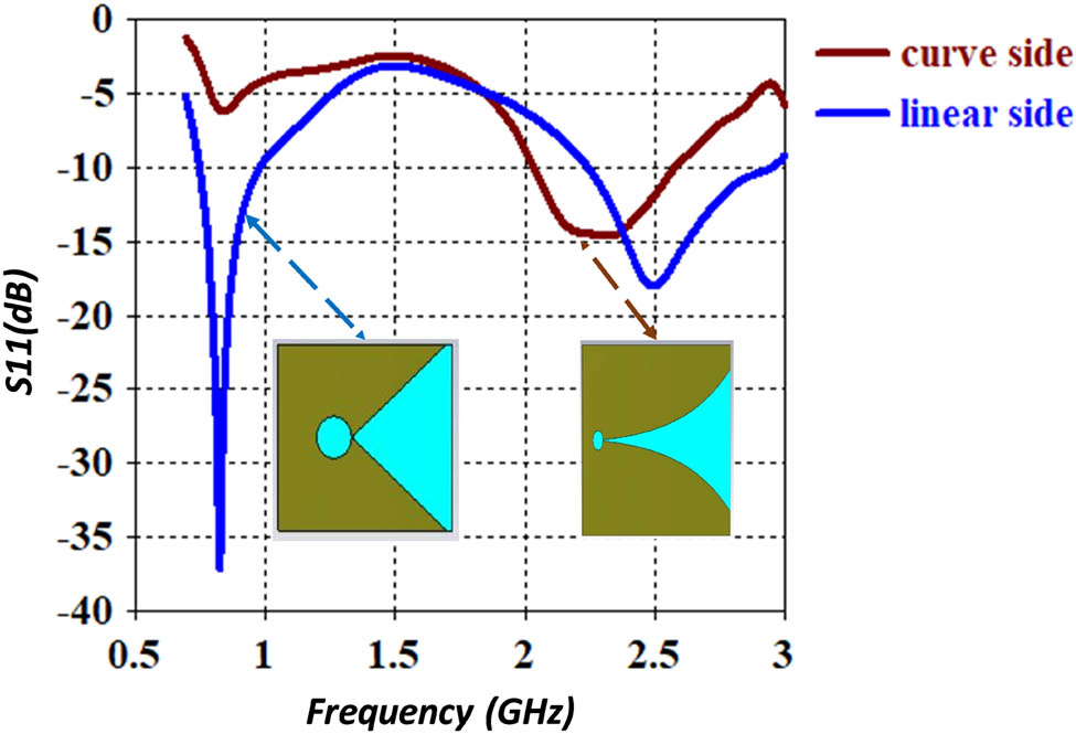
Simulated S11 responses of the proposed antenna with linear and taper slots.
Changing the curve to linear enables matching at bandwidths of 0.85 and 2.5 GHz. The reflection response of an antenna, S11, indicates bandwidths of 0.74–1.00 and 2.2–2.85 GHz with return losses of −35 and −23 dB at resonant frequencies of 0.85 and 2.5 GHz, respectively. The results demonstrate significant performance improvements achieved through slot geometry modification, which effectively altered the antenna’s electrical size and electromagnetic characteristics.
Figure 3 presents the physical prototype of the antenna, fabricated using a laser printer (LPKF S-103). The front view displays the copper-clad design with a circular slot, while the back view illustrates the feedline structure and the semi-circular matching stub.
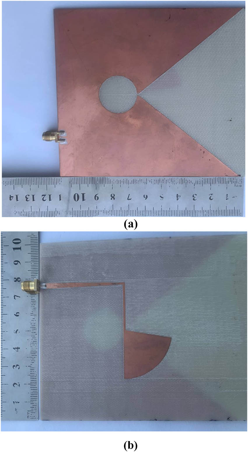
The fabricated antenna: (a) front view, and (b) back view.
The proposed antenna is supposed to be printed on a compact FR-4 substrate with a relative permittivity of 4.3 and dimensions of 115 × 100 × 1.6 mm3. All related parameters are shown in Figure 2, and the physical dimensions are presented in Table 1.
Parameters of the proposed antenna
| Parameter | Value (mm) | Parameter | Value (mm) |
|---|---|---|---|
| Wa | 100 | d | 11.36 |
| La | 115 | L coplar | 25.32 |
| Wf | 3.1 | W coup | 1 |
| h | 1.6 | r-stub | 25.84 |
| Lf | 47.7 | Ø-stub | 80 |
2.2 Measurements and simulation results
The impedance bandwidth of the Vivaldi antenna is illustrated in Figure 4, highlighting its operation across two frequency bands. There is a remarkable agreement between the simulated and measured reflection coefficients.
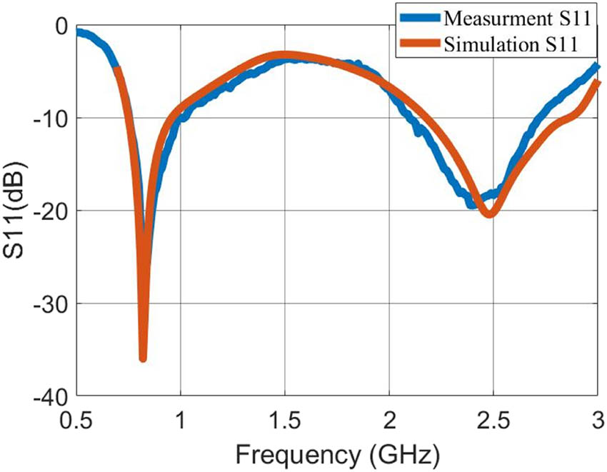
Comparison between the simulated and measured S-parameters for the fabricated antenna.
It can be noted that both curves display sharp dips at specific frequencies, indicating good antenna performance in these frequency bands. The differences between the measured and simulated results show that, in the upper band, the simulated resonant frequency is 2.50 GHz, while the measured resonant frequency is 2.49 GHz. This discrepancy is likely due to an unspecified value of ε r. Additionally, the variation in the bandwidth can be attributed to losses in the SMA connector.
Figure 5 displays the simulated realized gain and radiation efficiency for the proposed STVA antenna across the frequency range of 0.7–2.8 GHz. The antenna demonstrates dual-band characteristics with distinct performance regions. In the lower operational band (0.74–1.00 GHz), the gain reaches approximately 3 dBi with radiation efficiency exceeding 99%. A significant gain reduction is observed in the stopband region (1.0–2.2 GHz), where the gain drops to approximately 2 dBi, which is typical behavior for dual-band antenna designs. In the upper operational band (2.2–2.85 GHz), the antenna achieves peak gain values of 6.5 dBi with a radiation efficiency of 98.2%. The efficiency remains consistently high (>98%) across both operational bands, demonstrating the antenna’s effective electromagnetic energy conversion.

Simulated gain and efficiency of the resulting antenna vs frequency.
The gain variation between the two bands can be attributed to the different electrical lengths and current distribution patterns at the respective frequencies, which is characteristic of tapered slot antenna behavior.
Three-dimensional patterns at two frequencies, 0.8 and 2.5 GHz, clearly show that an antenna’s beam steering property is retained irrespective of its actual operating frequency over a range of values, as shown in Figure 6.

Simulated 3D radiation patterns: (a) 0.85 GHz and (b) 2.5 GHz.
3 Soil density compaction and moisture measurement
Two antennas were placed inside a wooden box filled with soil to investigate soil compaction and moisture levels. The signals were then transmitted by one antenna while the other received them using a VNA, from which MATLAB was used to analyze the data obtained. Figure 7 shows the two antennas located in the soil for parameters such as the received power, S21 phase, and delay time to realize how an antenna interacts under different soil conditions. The antenna’s responses are measured for each case of variation in the sand moisture content and density compaction.
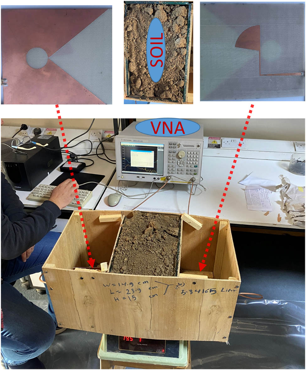
The two antennas with a soil sample in between are connected to the VNA.
3.1 Soil moisture measurement
In this study, an ANN was utilized to efficiently model soil properties by balancing simplicity and accuracy. A feed-forward architecture was applied, and backpropagation was used for straightforward implementation and tuning. Complex, non-linear interactions among soil parameters (such as delay time and phase) and actual compaction or moisture levels were effectively captured. By not requiring deep-learning structures, the ANN demonstrated both reliability and speed, making it highly suitable for in situ soil-sensing applications. Table 2 shows the effects of various parameters on S21, delay time, power, and phase, as determined using VNA and MATLAB. For neural network training on soil moisture measurements, a test was done with a soil-plugged box. This study covers data acquisition, signal pre-processing, and ANN design in MATLAB. By careful training and verification, the ANN model can accurately estimate soil density and moisture content, making it an all-encompassing, non-destructive material understanding approach.
Measurement results with different moisture percentages of water content
| Moisture (%) | Wet density (g/l) | Normalized peak power | Delay time (ns) | Maximum S21 (dB) | Phase in degree |
|---|---|---|---|---|---|
| 0.3 | 1371.4 | 0.2386 | 3.797 | 0.2088 | 41 |
| 4 | 1423.9 | 0.197 | 3.92 | 0.1911 | 83 |
| 5 | 1441.99 | 0.157 | 4.001 | 0.156 | 101 |
| 8 | 1486.1 | 0.1211 | 4.15 | 0.1061 | 145 |
| 13 | 1571.2 | 0.0882 | 4.133 | 0.094 | 140 |
The procedure involved collecting several data points by sending and receiving signals while adjusting the moisture contents of the testing box to vary between different readings of moisture levels, which aims at enabling the neural network to learn different associations between signal responses and a specific moisture level. The moisture percentage is calculated using Equation (1) [19], at a frequency of 0.82 GHz, and all measurements will be conducted on the lower band because lower frequencies provide deeper penetration into the soil.
This process was repeated several times with differing water contents.
3.2 Soil compaction measurement
Soil compaction was measured by placing two antennas, spaced 15 cm apart, in a container initially filled with dry soil without any compaction (Figure 7). Using these antennas, data on the S21 phase were collected directly from the measuring device, as illustrated in Table 3. The delay time is collected by using Equations (2)–(4).
Measured results of compaction percentages of water content
| Moisture (%) | Dry density (g/l) | Peak power (normalize) | Delay time (ns) | Maximum S21 (dB) | Phase of S21 (deg) | Compaction (%) |
|---|---|---|---|---|---|---|
| 0 | 1265.2 | 0.236 | 3.77 | 0.21 | 33 | 88.29 |
| 0 | 1325.3 | 0.242 | 3.784 | 0.21 | 37 | 92.48 |
| 0 | 1367 | 0.239 | 3.797 | 0.209 | 41 | 95.41 |
| 0 | 1395 | 0.241 | 3.804 | 0.21 | 43 | 97.34 |
| 0 | 1432 | 0.224 | 3.818 | 0.185 | 47 | 99.93 |
| 5 | 952.24 | 0.241 | 3.852 | 0.205 | 57 | 66.45 |
| 5 | 981.7 | 0.234 | 3.862 | 0.198 | 60 | 68.51 |
| 5 | 1014.7 | 0.227 | 3.872 | 0.191 | 63 | 70.81 |
| 5 | 1136.1 | 0.215 | 3.886 | 0.177 | 67 | 79.28 |
| 5 | 1261.3 | 0.201 | 3.97 | 0.189 | 92 | 88.01 |
| 5 | 1367.1 | 0.157 | 4.001 | 0.156 | 101 | 95.39 |
| 8 | 909.12 | 0.237 | 3.977 | 0.2 | 94 | 63.44 |
| 8 | 912.1 | 0.232 | 3.98 | 0.2 | 95 | 63.64 |
| 8 | 952.3 | 0.225 | 3.991 | 0.198 | 98 | 66.44 |
| 8 | 1015 | 0.21 | 3.994 | 0.179 | 99 | 70.83 |
| 8 | 1136 | 0.193 | 4.004 | 0.16 | 102 | 88.05 |
| 8 | 1367.1 | 0.121 | 4.15 | 0.106 | 145 | 95.40 |
| 8 | 1432.1 | 0.111 | 4.18 | 0.1 | 154 | 99.92 |
| 13 | 1015.8 | 0.179 | 4.014 | 0.163 | 105 | 70.88 |
| 13 | 1136.1 | 0.173 | 4.021 | 0.161 | 107 | 79.27 |
| 13 | 1226.1 | 0.157 | 4.045 | 0.147 | 114 | 85.59 |
| 13 | 1261 | 0.131 | 4.079 | 0.122 | 124 | 87.98 |
| 13 | 1325.6 | 0.102 | 4.129 | 0.105 | 139 | 92.5 |
| 13 | 1366.98 | 0.088 | 4.133 | 0.094 | 140 | 95.39 |
| 13 | 1432.11 | 0.057 | 4.194 | 0.054 | 158 | 99.93 |
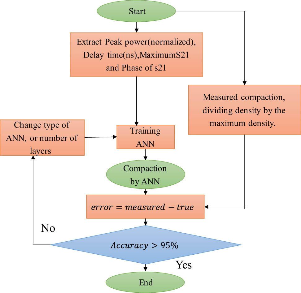
Afterward, the soil was gradually compacted in increments. At each step, signals were transmitted and received, and all relevant data were recorded at the resonant frequency. Density was calculated by dividing the soil mass by the volume of the box, while the measured compaction was determined by dividing the current density by the maximum achievable density.
In the second stage, water was added to the soil, and the moisture content was calculated according to Equation (1). The data collection process was then repeated in the same manner.
These data facilitated learning the relationship between the signal responses and soil compaction properties, ensuring accurate and reliable predictions for practical applications while transmitting and receiving signals through a VNA. The data were analyzed using MATLAB, where different soil moisture levels were systematically varied, enabling multiple measurements.
The systematic changes in the electromagnetic response are governed by fundamental dielectric mixing laws. As moisture content increases from 0 to 13%, water molecules (ε r ≈ 81) progressively replace air voids (ε r ≈ 1) in the soil matrix, significantly increasing the effective dielectric constant.
As the moisture percentage increases, the wet density increases, the phase angle decreases, and the delay time increases.
Equation (2) is used to calculate the total transit delay time t for a signal passing through a box containing multiple layers (air or soil, wood, and glass), based on the permittivity of each material [20,21]:
When the box is empty, the transit time is
When the box is empty, the phase is equal to 45° by VNA:
From this, the number of cycles is found to be n = 2. As the box is gradually filled with soil, the phase increases to a maximum and then returns to zero. This indicates that the total number of cycles has increased by one, making n = 3. By incorporating these measured values into Equation (4), the signal propagation time t can be determined. Subsequently, Equation (4) is used as follows:
Higher soil density reduces the air void ratios, replacing low-permittivity air pockets (ε r ≈ 1) with increased solid particle contact. This transition creates a more uniform dielectric medium dominated by soil particles, which typically have significantly higher permittivity values (ε r ≈ 2.5–8 for typical soil minerals) compared to air voids.
4 ANN training
The ANN model used in this study was developed in MATLAB and comprises three layers:
An input layer utilizing five parameters – moisture, normalized peak power, delay time (ns), maximum S21 (dB), and the phase of S21 (deg).
A hidden layer.
An output layer designed to predict soil compaction.
The network is a feed-forward backpropagation neural network. Specifically, this study utilizes two distinct feed-forward backpropagation networks. One is dedicated to measuring soil compaction, featuring a hidden layer with 20 neurons and employing the TANSIG (tangent-sigmoid) transfer function, as shown in Figure 8. The data were divided into two sets: 30% for training the neural network and 70% for validation. During the training phase, the five main parameters, along with the compaction level, are fed into the network to enable learning. The remaining 70% of the data are then used to test the network, which showed good predictive accuracy. Once training is complete, only five parameters are needed for the neural network to predict soil compaction.
The ANN model for measuring soil compaction.
These configurations enable the networks to effectively model non-linear relationships within the data, which is crucial for accurate, real-time assessment of soil properties.
Data were collected with these antennas, which recorded the soil’s electrical response to different soil compaction levels for both soil moisture and compact measurements. A second neural network was trained on these data to relate electromagnetic parameters such as S21, delay time, power, and phase to the percentages of soil compaction. Neural network models were trained iteratively by optimizing the number of neurons, epochs, and learning rates to distinguish training data from testing dataset sets for accuracy and reliability. The rigorous process of training and optimization involving neural networks showed that they have the potential to estimate density efficiently while being reliable in defining water content in soils; hence, they can be considered an effective tool for practical applications in geotechnical and civil engineering.
Table 4 shows the performance of the neural network in predicting dry density and soil compaction based on the collected data. The “measured” columns represent the actual measured values for dry density and compaction, while the “ANN” columns indicate the predictions made by the neural network. The error between the true and predicted values is calculated, and the performance index (PI) is used to measure the accuracy of the predictions, as shown in Figure 9.
Data analysis results using the neural network
| Compaction measured | Compaction by ANN |
|
|---|---|---|
| 88.296 | 84.856 | 96.10407182 |
| 92.485 | 91.960 | 99.43223083 |
| 95.414 | 94.908 | 99.46966703 |
| 97.348 | 96.843 | 99.48099332 |
| 99.936 | 99.748 | 99.81159438 |
| 70.804 | 71.077 | 99.61420334 |
| 79.278 | 78.961 | 99.59965005 |
| 88.021 | 88.283 | 99.70166796 |
| 95.390 | 95.564 | 99.81716546 |
| 66.452 | 66.47 | 99.96590209 |
| 68.510 | 68.659 | 99.78190101 |
| 70.812 | 70.895 | 99.8831042 |
| 79.280 | 79.524 | 99.69136723 |
| 88.019 | 88.16 | 99.83461041 |
| 95.394 | 96.015 | 99.34949776 |
| 63.442 | 63.444 | 99.99574796 |
| 88.296 | 84.856 | 96.10407182 |
| 92.485 | 91.960 | 99.43223083 |
| 95.414 | 94.908 | 99.46966703 |

Actual and measured ANN network of compaction.
The trained ANNs produced very accurate soil compaction indices with PIs above 99%. This system provides real-time information without having elaborate gadgets, making it an asset for field-based agricultural monitoring, civil engineering works, or even environmental evaluation due to its quickness and accuracy at the site.
The close overall tracking between the actual and predicted curves demonstrates the physical viability of using phase and delay measurements as reliable indicators for soil compaction analysis.
5 Comparison with previous work
In this section, a comparison is presented between the proposed antenna and previously published antennas, as well as with previous research that examined soil properties using GPR.
5.1 Comparative analysis of antenna
The proposed antenna provides significant improvements, as shown in Table 5. The compactness of a low-profile single-layer design measuring (0.266 × 0.306 × 0.003) λ 0 3, for better return loss; the proposed antenna operates in two bands: in the range of below −1 GHz frequency limit, having wide operational bandwidth from 0.74 to 1 GHz for large penetration, and between 2.2 and 3 GHz for small penetration, thereby offering an enormous advantage in terms of bandwidth against some previous models. In this case, the smaller size becomes significant for more applications. Furthermore, the proposed antenna’s radiation efficiency is at least 98%, compared with the high efficiencies (83–97%) reported by Hu et al. [25]. The proposed antenna demonstrates exceptional versatility, making it suitable for a wide range of applications. Its compact design and lower profile offer gains between 1.5 and 6.8 dB without requiring a reflector or array, maintaining efficiency in a smaller form factor. This makes it an ideal choice for wireless communication systems where space is limited. While it provides a balance between size, bandwidth, and gain, it is sufficient for many practical applications. Unlike more complex designs, such as those in Alwareth et al. [22], the system is flat, using single-layer solders. Consequently, this antenna proves its effectiveness through an easy manufacturing process, compactness, and relevance to modern-day wireless communication.
Comparison with previous works
| Ref. | [9] | [22] | [23] | [24] | [25] | [26] | [18] | [27] | Proposed (STVA) |
|---|---|---|---|---|---|---|---|---|---|
| Geometry | Vivaldi | Micro strip array | Vivaldi | Antipodal Vivaldi | Vivaldi | Podal and antipodal Vivaldi | Vivaldi | Vivaldi | Semi-Vivaldi |
| Antenna size (mm) | 220 × 256 × 1.6 | 166 × 66 × 20.1 | 210 × 216 × 170 | 450 × 600 × 1.5 | 240 × 240 × 289 | 90 × 74 × 1.6 | 49 × 48.4 × 1.5 | 200 × 200 × 1.6 | 100 × 115 × 1.6 |
| Electrical size (λ 0) | (0.78 × 0.78 × 0.05) | (2.4 × 0.99 × 0.024) | (0.24 × 0.28 × 0.2) | (0.45 × 0.6 × 0.0015) | (0.8 × 0.8 × 0.007) | (0.84 × 0.7 × 0.01) | (0.424 × 0.429 × 0.013) | (0.33 × 0.33 × 0.0027) at 0.5 GHz | (0.266 × 0.306 × 0.003) |
| Frequency (GHz) | 0.8 to 6.0 | 3.5 to 5.8 | 0.4 to 4 | 0.3 to 2 | 0.9 to 4 | 2.8 to 16 | 2.63 above 12 | 0.39 to 1.5 | 0.74 to 1.00 and 2.2 to 3 |
| Problem formulation | Large size | Microstrip array integrated with FSS | Large electric height of 0.2 and array antennas | Complex design | Array, directors, “H”-shaped metamaterial units | Large electrical size array | Low efficiency | Negative gain at low frequency, efficiency not addressed | Compact size and high efficiency (98%) |
| Min. gain (dBi) | 2.1 at 0.8 GHz | — | 4 | 4.4 | 6.7 | 2 dBi at 3 GHz | 1 | — | 1.5 |
| Max. gain (dBi) | 11 | 12 | 12 | 11.5 | 15 | 10.4 | 1 to 3.8 | 5 | 6.8 |
| Total/radiation efficiency | In-band radiation efficiency is better than 65% | Rad 72–77% | 85–95% | null | Rad 83–97% | Null | 86% rad | Null | 99.8/rad.\97.7 total |
| 68% total |
5.2 Comparative analysis of applications
The proposed antenna offers significant improvements, as highlighted in Table 6. These include direct phase difference and delay time measurements obtained from the VNA, which are then correlated with soil compaction and moisture. This approach considers the increase in permittivity resulting from higher compaction and moisture levels, thereby directly impacting the assessment of these properties. Unlike traditional methods that rely on images captured by GPR, this method focuses on real-time data acquisition and analysis.
Comparison of the proposed model with previous studies
| Ref. | Device technology | Application | Parameters |
|---|---|---|---|
| [21] | GPR | Moisture and permittivity measurement | Envelope voltage (mV) |
| [20] | GPR | Permittivity measurement | Analytic peak ratio method |
| [27] | VNA | Objects detection | B- SCANE |
| [28] | 1,700 MHz GPR | Soil compaction | Reflectivity signal |
| [29] | SIR-3000 | Soil moisture monitoring | Delay time |
| 1,600 MHz GPR | |||
| [30] | VNA | Concrete moisture monitoring | Amplitude of S11 |
| Proposed (STVA) | VNA | Soil compaction, permittivity, and moisture measurement | Phase, delay time, and s21 |
6 Conclusions
The antennas used in this study are compact, planar STVA fabricated on a single substrate with an electrical size of (0.266 × 0.306 × 0.003) λ 0 3. The tapered section of the traditional Vivaldi antenna is modified with a straight side instead of the traditional curved shape, simplifying the fabrication, improving specific characteristics, and downshift of the desired frequency.
The antenna demonstrates excellent dual-band performance with resonant frequencies at 0.74–1.00 GHz (31% bandwidth) and 2.2–2.85 GHz (26% bandwidth), with gains of 2–6.5 dB and radiation efficiency exceeding 98%. The straight-tapered slot geometry modification significantly improved impedance matching compared to traditional curved Vivaldi designs, with S11 values reaching −35 dB at resonant frequencies. These compact antennas are designed for measurements of soil properties.
The compact size and low profile of the antennas make them easy to deploy, reducing costs and system complexity. Additionally, their design enables direct soil insertion without requiring supplementary components or elaborate setups, enhancing their practicality and reliability for field measurements.
The study establishes clear physical relationships between soil electromagnetic properties and mechanical characteristics. Increased soil compaction reduces air voids (εᵣ = 1) and increases water content (εᵣ = 81), resulting in higher effective dielectric constants that cause measurable increases in signal delay time and phase shifts. This fundamental understanding enables reliable soil property prediction through electromagnetic wave propagation analysis. By extracting these parameters using a VNA, the compaction level can be accurately predicted.
This approach offers a reliable, non-destructive alternative to traditional testing methods. Furthermore, the underlying mechanism can be extended to detect voids and defects in other materials, such as concrete or foam. The proposed system also shows promise for related applications, including sand gradation analysis. Based on this principle, the system can also be used as an effective tool for non-destructive detection of internal defects and voids within materials.
-
Funding information: The authors state no funding involved.
-
Author contributions: Dr. Ali J. Salim proposed the fundamental research idea and provided overall supervision for the project, while Mohammed K. Abbas handled the implementation of programs, designs, and the majority of the practical work, including antenna design, CST simulations, data management, and writing the original draft of the research. Dr. Raaed T. Hammed made a significant contribution by developing the ANN section and conducting technical analysis of the results. Dr. Aduwati Sali contributed her expertise in supporting antenna design and testing, as well as reviewing and editing the manuscript, while providing necessary support for funding acquisition. The research team integrated to achieve the project objectives by combining diverse expertise in antenna design, ANNs, and experimental verification.
-
Conflict of interest: The authors state no conflict of interest.
-
Data availability statement: The data supporting the findings of this study are available from the corresponding author upon reasonable request.
References
[1] Bhattacharjee A, Bhawal A, Karmakar A, Saha A. Design of an antipodal Vivaldi antenna with fractal‐shaped dielectric slab for enhanced radiation characteristics. Microw Opt Technol Lett. 2020;62:2066–74. 10.1002/mop.32274.Search in Google Scholar
[2] Yerrola AK, Ali M, Arya RK, Murmu L. Design of wideband conformal Vivaldi antenna array. 2022 URSI Reg. Conf. Radio Sci. USRI-RCRS 2022. IEEE; 2022. p. 1–3. 10.23919/URSI-RCRS56822.2022.10118483.Search in Google Scholar
[3] Wagner S, Hossain A, Pancrazio S, Pham AV. System-based specifications for better design of ground-penetrating radar antennas. IET Microwaves Antennas Propag. 2023;17:478–93. 10.1049/mia2.12358.Search in Google Scholar
[4] Serhir M, Lesselier D. Wideband reflector-backed folded bowtie antenna for ground penetrating radar. IEEE Trans Antennas Propag. 2018;66:1056–63. 10.1109/TAP.2017.2786295.Search in Google Scholar
[5] Zerrad F-E, Taozari M, El Aoufi J, Abdulkarim YI, Jarndal A, Almajali E. Slotted antipodal Vivaldi antenna for multiple ultra-wide band applications including IoT. In 2023 Advances in Science and Engineering Technology International Conferences. IEEE; 2023. p. 1–4. 10.1109/ASET56582.2023.10180723.Search in Google Scholar
[6] Jaiswal PK, Bhattacharya R, Kumar A. A UWB antipodal Vivaldi antenna with high gain using metasurface and notches. AEU-Int J Electron Commun. 2023;159:154473. 10.1016/j.aeue.2022.154473.Search in Google Scholar
[7] Yuan W, Huang J, Zhang X, Cui K, Wu W, Yuan N. Wideband pattern-reconfigurable antenna with switchable monopole and vivaldi modes. IEEE Antennas Wirel Propag Lett. 2022;22:199–203. 10.1109/LAWP.2022.3207199.Search in Google Scholar
[8] Guruswamy S, Chinniah R, Thangavelu K. A printed compact UWB Vivaldi antenna with hemi cylindrical slots and directors for microwave imaging applications. AEU-Int J Electron Commun. 2019;110:152870. 10.1016/j.aeue.2019.152870.Search in Google Scholar
[9] Huang X, Cao J, Zhong W, Jin X. High gain antipodal Vivaldi antenna with novel V-shaped air-slot. Int J RF Microw Comput Eng. 2021;31:1–9. 10.1002/mmce.22818.Search in Google Scholar
[10] Babu GH, Srinivas M, Gnanaprakasam C, Prabu RT, Devi MR, Ahammad SH, et al. Meander line base asymmetric co-planar wave guide (CPW) feed tri-mode antenna for Wi-Max, North American Public Safety and satellite applications. Plasmonics. 2023;18:1007–18.10.1007/s11468-023-01826-9Search in Google Scholar
[11] Jahan K, Srinivas P, Ahammad SH, Livingston LMM, Anwer TMK, Kiran KU, et al. Superior gain and polarization control in MIMO circular ring surface plasmonic planar differential antenna for wireless systems. Plasmonics. 2023;18:877–87.10.1007/s11468-023-01818-9Search in Google Scholar
[12] Lavadiya SP, Sorathiya V, Kanzariya S, Chavda B, Naweed A, Faragallah OS, et al. Low profile multiband microstrip patch antenna with frequency reconfigurable feature using PIN diode for S, C, X, and Ku band applications. Int J Commun Syst. 2022;35:e5141.10.1002/dac.5141Search in Google Scholar
[13] Saikumar K, Ahammad SH, Vani KS, Anwer TMK, Hadjouni M, Menzli LJ, et al. Improvising and enhancing the patterned surface performance of MIMO antenna parameters and emphasizing the efficiency using tampered miniature sizes and layers. Plasmonics. 2023;18:1771–86.10.1007/s11468-023-01886-xSearch in Google Scholar
[14] Kundu D, Reza AW, Kannan V, Vijayakumar S, Ramkumar G, Ferdous AHMI, et al. Synthesis and optimization of a compact wideband trapezoidal–stepped patch antenna for dual-band applications. Plasmonics. 2025;20:3007–28.10.1007/s11468-025-02789-9Search in Google Scholar
[15] Aras U, Delwar TS, Durgaprasadarao P, Sundar PS, Ahammad SH, Eid MMA, et al. Dual features, compact dimensions and X-band applications for the design and fabrication of annular circular ring-based crescent-moon-shaped microstrip patch antenna. Micromachines. 2024;15(7):809. 10.3390/mi15070809.Search in Google Scholar PubMed PubMed Central
[16] Abbas MK, Hammed RT, Salim AJ, Sali A. A high-efficiency, indirectly-fed, dual moon-shaped printed antenna for measuring sand gradation. 2024 IEEE 7th Int. Symp. Telecommun. Technol. IEEE; 2024. p. 31–6.10.1109/ISTT63363.2024.10750705Search in Google Scholar
[17] Srinivas M, Reddy GRK, Sangeethapriya S, Neelamegam N, Balasubramanian B, Jahan K, et al. Design and fabrication development of slotted T-shaped patch antenna with symmetrical CPW feed for IOT and ITU applications. Plasmonics. 2024;19:1–10.10.1007/s11468-024-02553-5Search in Google Scholar
[18] Chaabane A, Guerroui M. A planar dual notched band Vivaldi antenna for wireless communication applications. Def Sci J. 2024;74:79–84. 10.14429/dsj.74.19154.Search in Google Scholar
[19] Sumner ME. Handbook of soil science. Boca Raton, FL, USA: CRC press; 1999.Search in Google Scholar
[20] Rohman BPA, Nishimoto M, Ogata K. Material permittivity estimation using analytic peak ratio of air-coupled GPR signatures. IEEE Access. 2022;10:13219–28. 10.1109/ACCESS.2022.3147217.Search in Google Scholar
[21] He Y, Fang L, Peng S, Liu W, Cui C. A ground-penetrating radar-based study of the structure and moisture content of complex reconfigured soils. Water (Switz). 2024;16(23):2332. 10.3390/w16162332.Search in Google Scholar
[22] Alwareth H, Ibrahim IM, Zakaria Z, Al-Gburi AJA, Ahmed S, Nasser ZA. A wideband high-gain microstrip array antenna integrated with frequency-selective surface for Sub-6 GHz 5G applications. Micromachines. 2022;13:1215.10.3390/mi13081215Search in Google Scholar PubMed PubMed Central
[23] Yucel AC, Sun H-H, Lee YH, Luo W, Ow LF, Yusof MLM, et al. Compact dual-polarized Vivaldi antenna with high gain and high polarization purity for GPR applications. Sensors. 2021;21:503. 10.3390/s21020503.Search in Google Scholar PubMed PubMed Central
[24] Guo J, Tong J, Zhao Q, Jiao J, Huo J, Ma C. An ultrawide band antipodal Vivaldi antenna for airborne GPR application. IEEE Geosci Remote Sens Lett. 2019;16:1560–4. 10.1109/LGRS.2019.2905013.Search in Google Scholar
[25] Hu R, Zhang F, Ye S, Fang G. Ultra-wideband and high-gain Vivaldi antenna with artificial electromagnetic materials. Micromachines. 2023;14:1329. 10.3390/mi14071329.Search in Google Scholar PubMed PubMed Central
[26] Ghimire J, Choi D-YY. Ultra-wide band double-slot podal and antipodal Vivaldi antennas feed by compact out-of-phase power divider slot for fluid properties determination. Sensors. 2022;22:4543. 10.3390/s22124543.Search in Google Scholar PubMed PubMed Central
[27] Prasanth A, Abhinav P, Ramachandran A, Kanakaraj A, Sajith K, Ajith KK. Experimental ground penetrating radar using vector network analyzer. 2024 IEEE Space, Aerospace and Defence Conference. IEEE; 2024. p. 15–8.10.1109/SPACE63117.2024.10668133Search in Google Scholar
[28] Shapovalov V, Vasilchenko A, Yavna V, Kochur A. GPR method for continuous monitoring of compaction during the construction of railways subgrade. J Appl Geophys. 2022;199:104608. 10.1016/j.jappgeo.2022.104608.Search in Google Scholar
[29] Marchenaa JP, Françosob MT, Treiberc HM, de Oliveira Stenicod N. Assessment and monitoring of moisture content variation in compacted tropical soil using GPR data. Rev Ing Constr. 2023;38:334–48. 10.7764/RIC.00073.21.Search in Google Scholar
[30] Teng KH, Kot P, Muradov M, Shaw A, Hashim K, Gkantou M, et al. Embedded smart antenna for non-destructive testing and evaluation (NDT&E) of moisture content and deterioration in concrete. Sensors. 2019;19:547.10.3390/s19030547Search in Google Scholar PubMed PubMed Central
© 2025 the author(s), published by De Gruyter
This work is licensed under the Creative Commons Attribution 4.0 International License.
Articles in the same Issue
- Research Articles
- Modification of polymers to synthesize thermo-salt-resistant stabilizers of drilling fluids
- Study of the electronic stopping power of proton in different materials according to the Bohr and Bethe theories
- AI-driven UAV system for autonomous vehicle tracking and license plate recognition
- Enhancement of the output power of a small horizontal axis wind turbine based on the optimization approach
- Design of a vertically stacked double Luneburg lens-based beam-scanning antenna at 60 GHz
- Synergistic effect of nano-silica, steel slag, and waste glass on the microstructure, electrical resistivity, and strength of ultra-high-performance concrete
- Expert evaluation of attachments (caps) for orthopaedic equipment dedicated to pedestrian road users
- Performance and rheological characteristics of hot mix asphalt modified with melamine nanopowder polymer
- Second-order design of GNSS networks with different constraints using particle swarm optimization and genetic algorithms
- Impact of including a slab effect into a 2D RC frame on the seismic fragility assessment: A comparative study
- Analytical and numerical analysis of heat transfer from radial extended surface
- Comprehensive investigation of corrosion resistance of magnesium–titanium, aluminum, and aluminum–vanadium alloys in dilute electrolytes under zero-applied potential conditions
- Performance analysis of a novel design of an engine piston for a single cylinder
- Modeling performance of different sustainable self-compacting concrete pavement types utilizing various sample geometries
- The behavior of minors and road safety – case study of Poland
- The role of universities in efforts to increase the added value of recycled bucket tooth products through product design methods
- Adopting activated carbons on the PET depolymerization for purifying r-TPA
- Urban transportation challenges: Analysis and the mitigation strategies for road accidents, noise pollution and environmental impacts
- Enhancing the wear resistance and coefficient of friction of composite marine journal bearings utilizing nano-WC particles
- Sustainable bio-nanocomposite from lignocellulose nanofibers and HDPE for knee biomechanics: A tribological and mechanical properties study
- Effects of staggered transverse zigzag baffles and Al2O3–Cu hybrid nanofluid flow in a channel on thermofluid flow characteristics
- Mathematical modelling of Darcy–Forchheimer MHD Williamson nanofluid flow above a stretching/shrinking surface with slip conditions
- Energy efficiency and length modification of stilling basins with variable Baffle and chute block designs: A case study of the Fewa hydroelectric project
- Renewable-integrated power conversion architecture for urban heavy rail systems using bidirectional VSC and MPPT-controlled PV arrays as an auxiliary power source
- Exploitation of landfill gas vs refuse-derived fuel with landfill gas for electrical power generation in Basrah City/South of Iraq
- Two-phase numerical simulations of motile microorganisms in a 3D non-Newtonian nanofluid flow induced by chemical processes
- Sustainable cocoon waste epoxy composite solutions: Novel approach based on the deformation model using finite element analysis to determine Poisson’s ratio
- Impact and abrasion behavior of roller compacted concrete reinforced with different types of fibers
- Architectural design and its impact on daylighting in Gayo highland traditional mosques
- Structural and functional enhancement of Ni–Ti–Cu shape memory alloys via combined powder metallurgy techniques
- Design of an operational matrix method based on Haar wavelets and evolutionary algorithm for time-fractional advection–diffusion equations
- Design and optimization of a modified straight-tapered Vivaldi antenna using ANN for GPR system
- Analysis of operations of the antiresonance vibration mill of a circular trajectory of chamber vibrations
- Functions of changes in the mechanical properties of reinforcing steel under corrosive conditions
- 10.1515/eng-2025-0153
- Review Articles
- A modified adhesion evaluation method between asphalt and aggregate based on a pull off test and image processing
- Architectural practice process and artificial intelligence – an evolving practice
- Enhanced RRT motion planning for autonomous vehicles: a review on safety testing applications
- Special Issue: 51st KKBN - Part II
- The influence of storing mineral wool on its thermal conductivity in an open space
- Use of nondestructive test methods to determine the thickness and compressive strength of unilaterally accessible concrete components of building
- Use of modeling, BIM technology, and virtual reality in nondestructive testing and inventory, using the example of the Trzonolinowiec
- Tunable terahertz metasurface based on a modified Jerusalem cross for thin dielectric film evaluation
- Integration of SEM and acoustic emission methods in non-destructive evaluation of fiber–cement boards exposed to high temperatures
- Non-destructive method of characterizing nitrided layers in the 42CrMo4 steel using the amplitude-frequency technique of eddy currents
- Evaluation of braze welded joints using the ultrasonic method
- Analysis of the potential use of the passive magnetic method for detecting defects in welded joints made of X2CrNiMo17-12-2 steel
- Analysis of the possibility of applying a residual magnetic field for lack of fusion detection in welded joints of S235JR steel
- Eddy current methodology in the non-direct measurement of martensite during plastic deformation of SS316L
- Methodology for diagnosing hydraulic oil in production machines with the additional use of microfiltration
- Special Issue: IETAS 2024 - Part II
- Enhancing communication with elderly and stroke patients based on sign-gesture translation via audio-visual avatars
- Optimizing wireless charging for electric vehicles via a novel coil design and artificial intelligence techniques
- Evaluation of moisture damage for warm mix asphalt (WMA) containing reclaimed asphalt pavement (RAP)
- Comparative CFD case study on forced convection: Analysis of constant vs variable air properties in channel flow
- Evaluating sustainable indicators for urban street network: Al-Najaf network as a case study
- Node failure in self-organized sensor networks
- Comprehensive assessment of side friction impacts on urban traffic flow: A case study of Hilla City, Iraq
- Design a system to transfer alternating electric current using six channels of laser as an embedding and transmitting source
- Security and surveillance application in 3D modeling of a smart city: Kirkuk city as a case study
- Modified biochar derived from sewage sludge for purification of lead-contaminated water
- The future of space colonisation: Architectural considerations
- Design of a Tri-band Reconfigurable Antenna Using Metamaterials for IoT Applications
- Special Issue: AESMT-7 - Part II
- Experimental study on behavior of hybrid columns by using SIFCON under eccentric load
- Special Issue: ICESTA-2024 and ICCEEAS-2024
- A selective recovery of zinc and manganese from the spent primary battery black mass as zinc hydroxide and manganese carbonate
- Special Issue: REMO 2025 and BUDIN 2025
- Predictive modeling coupled with wireless sensor networks for sustainable marine ecosystem management using real-time remote monitoring of water quality
- Management strategies for refurbishment projects: A case study of an industrial heritage building
- Structural evaluation of historical masonry walls utilizing non-destructive techniques – Comprehensive analysis