Energy efficiency and length modification of stilling basins with variable Baffle and chute block designs: A case study of the Fewa hydroelectric project
-
Vishan Dahal
 and
Shrawan Neupane
and
Shrawan Neupane

Abstract
Stilling basin, a hydraulic structure that is commonly placed downstream of the spillways or outlets for decreasing the energy of the flow and consequently the erosion, and protecting hydraulic structures. This study investigates innovative methods to improve stilling basin performance through enhanced energy dissipation and reduced basin length using FLOW-3D 2023R2. Eight numerical models were analyzed, focusing on total energy dissipation and depth-averaged velocity. Five models outperformed the baseline (Model 1), where Model 6, incorporating honeycomb structures as the basin’s blocks, emerged as the most effective by achieving 67% energy dissipation. However, by reducing the length of stilling, Model 2 with honeycomb baffle blocks was able to reduce the basin length by 11.8% without exceeding the threshold limits. The results indicate that honeycomb structures enhance energy dissipation in stilling basins due to their labyrinthine structures, which promote numerous turbulences and energy dispersion and reduce the basin volume, offering a practical solution to hydraulic engineering applications. These conclusions may present significant implications for the enhancement of stilling basins and suggest further study on honeycomb structures from hydraulic engineering perspectives.
1 Introduction
Hydropower, a reliable renewable energy source, faces challenges in construction and operation, especially during floods. Hydraulic structures, particularly dam headworks, are vulnerable to high flood events. A spillway is crucial for safely releasing excess water from a reservoir or river to downstream areas [1]. The velocity of water passing through a spillway is so high that it is liable to cause erosion of the bed channel immediately below the top of the structure [2]. To stabilize riverbed sediment transport, mitigate the impacts of hydropower sustainability [3], and prevent riverbed erosion at downstream and dam undermining, the incorporation of an energy dissipator at the base of structures is needed to dissipate high-velocity flow energy and establish safe flow conditions in the outlet [4]. The stilling basin is crucial in dissipating the excess energy retained by dams, ensuring the integrity of headworks [5,6]. Before entering the river, the flow downstream of the spillway structure should return to its normal state. To reduce the risk of structural instability and to maximize the energy dissipator’s hydraulic performance, the energy dissipation must be accurately assessed [7,8]. A hydraulic jump is a crucial technique used by hydraulic engineers to design stilling basins, acting as an energy dissipater [9,10]. The dimensions of hydraulic jump stilling basins depend on the jump length and sequent depth [11]. Many efforts have been made to reduce the size of hydraulic jump stilling basins by using baffle blocks and end sills for modifying the jump characteristics to obtain comparable or better performance in shorter lengths [12]. For the dam structure to be both economical and efficient, the stilling basin design must be optimized [13,14]. The addition of chutes and basin blocks hinders and elevates water flow, reducing the basin length and concrete usage, thus lowering construction costs [15]. These blocks stabilize the jump under normal conditions, ensuring that it remains steady and not drained or washed out [16]. The impacts of these blocks are determined by their placement, height, and the gap that separates them [17].
During the past decades, many attempts have been made to reduce the size of stilling basins and enhance their energy dissipation efficiency by forcing the jump to occur within a short distance of the apron using various types of basin appurtenances [18,19]. These appurtenances act as hydraulic structures that facilitate the dissipation of potential energy retained by the dam or barrage [20]. Hayder [21] studied the stilling basins and found that rough beds with semi-circular shapes reduced the hydraulic jump length by 56% and the tail water depth by 25% with the same Froude number, compared to various basins like USBR-I, USBR-II, USBR-III, USBR-IV, and SAF. Abbas et al. [22] studied hydraulic jump characteristics in a stilling basin with adverse slope change. They used baffle blocks with different configurations to alter the basin's dimensions and test their effects on hydraulic jump characteristics. The results showed that baffle blocks reduced the sequent depth ratio, length of jump ratio, and roller length, but increased the energy dissipation ratio. According to Elnikhely [23], water dissipates more energy when it forms over staggered cylinder blocks that are fixed to a spillway; the least amount of energy is lost in a diagonal arrangement. Bestawy [24] compared the hydraulic performance of 14 different shapes of baffle blocks in a stilling basin, including semi-circular, triangular, trapezoidal, and rectangular shapes in different orientations setting inflow as Froude numbers 5–9, where the semi-circular shape was found to be the most efficient, as it significantly reduced parameters like the sequent depth ratio and hydraulic jump length compared to other shapes. Kang [25] conducted an experimental study to assess the impact of different shapes of baffle blocks on flow dissipation downstream of a weir. The study involved five different baffle block shapes, installed on a fixed bed, under two discharge values (0.140 and 0.325 m3/s). The flow rate downstream of the weir was measured with and without baffles, and the results indicated that square baffle blocks provided a significant flow dissipation effect. Gubashi et al. [26] analyzed how stepped spillway configurations influence flow turbulence and energy loss, offering insights into the impact of geometric variations. A study by Zaffar and Hassan [27] examined the Taunsa Barrage in Pakistan, focusing on the remodeling of a stilling basin built in 1958 that was later remodeled in 2008, modifying chute blocks and baffle blocks. Various hydraulic parameters were compared and analyzed using Flow-3D, and the new basin had minimal energy dissipation and significant scouring. Djunur et al. [28] further examined how baffle block angles affect jump behavior in porous rectangular designs, offering a new perspective on geometric optimization. Bakhtyar et al. [29] used a dynamic programming procedure to optimize the cascade stilling basin design of Tehri Dam to minimize excavation and concrete work costs, which shows a 31% improvement in minimizing concrete and excavation volumes and construction costs. These studies underscore the impact of shape, orientation, and flow interaction in stilling basin performance and form the conceptual foundation for the novel block designs explored in this study.
Although there have been several studies on the stilling basin design and efficiency of energy dissipation, there remains limited exploration of innovative geometries in a comparative modeling framework. Most research work focuses on traditional designs and misses out on modification strategies, balancing energy dissipation with the compactness of structure. Advances in computer technology have made it possible to examine the hydraulic modeling of full-scale spillways and barrage bays with the use of more effective computational fluid dynamics (CFD) techniques [30]. Yamini et al. [31] demonstrated the effectiveness of CFD modeling in evaluating the hydraulic performance of seawater intake systems, showcasing the adaptability of numerical simulations in complex flow systems and underlining the growing reliance on CFD tools for advancing hydraulic design. Using a FLOW-3D model, the energy dissipation efficiency of a stilling basin is examined in this study. The objective of this study is to numerically evaluate the performance of modified stilling basin geometries using FLOW-3D, focusing on improving energy dissipation and minimizing basin length. This research work is unique in that it modifies stilling basin appurtenances, including curved, triangular, and honeycomb structures, with the regular types recommended by the USBR by altering the geometry of the baffle and chute blocks, which aids in improving the flow characteristics within the basin and increasing energy dissipation close to the floor. By conducting simulations using Flow3D Hydro and analyzing the results, the research determines the most efficient shape for energy dissipation. These findings will contribute to the modification of stilling basin design and enhance its hydraulic performance. Through this approach, the study lends momentum toward more efficient, economical, and compact stilling basin design insights with practical solutions for modern hydropower development.
2 Materials and methods
2.1 Study area
The study site is the stilling basin of the Fewa Hydroelectric Project, located in Pokhara City of Kaski district of Nepal, which harnesses the outflow of Fewa Lake and has been operational since its commissioning in 1969 [32]. Developed collaboratively by the governments of India and Nepal, this canal-drop-type power station has an installed capacity of 1 MW with a total design generation of 6.5 GWh annually [33]. The stilling basin at the Fewa Hydropower Project is equipped with key appurtenances such as chute blocks and basin blocks, which are essential for controlling turbulent flow and ensuring energy dissipation. By examining these hydraulic structures, the study aims to enhance the understanding of flow dynamics within the basin and contribute to future design improvements for hydropower systems.
2.2 Data collection
A comprehensive data collection campaign was conducted at the selected site, including detailed surveys and measurements of hydraulic parameters such as stilling basin dimensions, chute blocks, baffle blocks, dam height, and water level. These measurements provided critical insights into hydraulic conditions at the site, forming the basis for subsequent modeling. Furthermore, annual maximum precipitation data at stations 0804 (Pokhara Airport) and 0814 (Lumle) from 2003 to 2020 were obtained from the Department of Hydrology and Meteorology (DHM), Nepal, for calculating 1,000-year design discharge. This extensive dataset provided a solid basis for the study's modeling and analysis stages, allowing for the realistic simulation of the stilling basin’s hydraulic behavior. Additionally, by systematically altering the spillway gate openings, different discharge conditions measured in the field were achieved. For each gate setting, the corresponding flow discharge was calculated, and the downstream flow depth at the 35 m section was measured in the field.
2.3 Methodology
The methodology adopted in this research modifies the length of the stilling basin for energy dissipation and hydraulic performance with reference to Model 1, which replicates the hydraulic structure of the stilling basin of the Fewa Hydroelectric Project at field conditions. The different arbitrary geometries of the chutes and baffles blocks were chosen as different models, which aid in maximizing energy dissipation. The approach was systematic in site selection, data collection, 3D model creation, and CFD simulations using Flow3D Hydro. This multivariate process was a composite of model comparison, modification, and performance evaluation to determine the efficient flow characteristic optimal basin length. Field data and advanced modeling techniques were combined to simulate the complex hydraulic phenomenon within the basin of unsteady flow conditions accurately. It was done by varying the length across different models within a specified range based on the preliminary design information for iterative simulations to be carried out on the impacts against hydraulic parameters toward maximizing energy dissipation operational efficiency. The length reduction of every model (Mn) continued until the total energy (E 2) and velocity (v 2) at 35 m downstream from the dam heel exceeded the threshold values established by the baseline Model 1 (M1). This modification process gives well in advance recommendations on how to design and build effective stilling basins, thereby giving valuable insights for future study. A flow chart outlining the methodological procedure was developed prior to conducting the study and analysis, as shown in Figure 1.
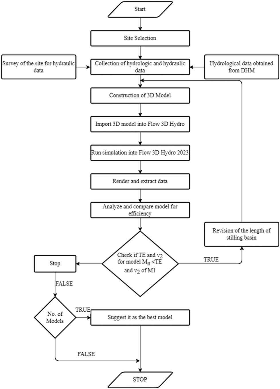
Methodological flowchart.
2.4 Construction of a 3D model
Data from the site were processed using AutoCAD to plot all the required dimensions and features for the three-dimensional model. The AutoCAD file was then exported into the SketchUp, where the final 3D model was generated to replicate the hydraulic parameters of the Stilling basin at field conditions, measuring a length of 21.23 m, a width of 28 m, and a 1.57 m high end sills comprising chute and baffle blocks, as shown in Figure 2(a). Different block configurations were designed to enhance energy dissipation and improve hydraulic performance in the stilling basin to replace the existing chute and baffle blocks, as described in Table 1. Model 1 represents the actual configuration of the Fewa Hydropower Project and served as the baseline. Models 3–5 (curved blocks on horizontal/vertical surfaces and triangular blocks) were inspired by various previous studies on alternative baffle shapes aiming to enhance energy dissipation [21,24,25], where different geometries such as trapezoidal, semicircular, and triangular blocks showed improved turbulence and flow resistance. Models 2 and 6–8, which incorporate honeycomb-shaped blocks, represent novel design propositions. These designs were developed based on the hypothesis that their increased surface complexity and turbulence-inducing cavities could improve dissipation and reduce required basin length. The uniformity in block size across all models ensured a comparable blockage ratio, allowing fair performance assessment among geometries. In this respect, the 3D model was exported to Flow3D Hydro in order to allow for enhanced hydraulic behavior assessment. This functionality allowed for an effective evaluation of the stilling basin geometry, supporting the modification process. The approach provided herein ensures testing of various configurations of blocks and identification of the most feasible length of the stilling basin for each model.

(a) Model 1 confirming as per existing field conditions, (b) Model 2 with honeycomb baffle blocks, (c) Model 3 with curved (on horizontal surface) blocks as baffle blocks and chute blocks, (d) Model 4 with curved shape (on vertical surface) baffle blocks and chute blocks, (e) Model 5 with triangular baffle blocks and chute blocks, (f) Model 6 with honeycomb baffle blocks and chute blocks, (g) Model 7 with honeycomb staggered baffles blocks and chute blocks, and (h) Model 8 with two series of honeycomb baffle blocks and no chute blocks.
Description of different model block configurations
| Model | Description | Chute blocks | Baffle blocks |
|---|---|---|---|
| Model 1 | Model confirming as per existing field condition (Figure 2(a)) | 2.47 m long, 2.15 m high, and 1.73 m wide | 2.57 m long, 2.15 m high, and 1.61 m wide |
| Thickness at top = 0.43 m | |||
| Model 2 | Model with honeycomb baffle blocks (Figure 2(b)) | 2.47 m long, 2.15 m high, and 1.73 m wide | 2.15 m × 2.15 m × 2.15 m honeycomb blocks, featuring 1.42 m diameter cylindrical slots with a 2.03 m diameter spherical cut at the center |
| Model 3 | Model with curved (on horizontal surface) blocks as baffle blocks and chute blocks (Figure 2(c)) | Curved block with 2.15 m long, 2.15 m wide, and 2.15 m high, and horizontal surfaces cut in a curved manner by a cylindrical surface with a diameter of 1.65 m. It shows a trapezoidal shape from side view, with a width of 2.15 m at the bottom and a reduced width of 1.07 m at the top | Curved block with 2.15 m long, 2.15 m wide, and 2.15 m high, and horizontal surfaces cut in a curved manner by a cylindrical surface with a diameter of 1.65 m. It shows a trapezoidal shape from side view, with a width of 2.15 m at the bottom and a reduced width of 1.07 m at the top |
| Model 4 | Model with curved shape (on vertical surface), baffle blocks, and chute blocks (Figure 2(d)) | Curved block with 2.15 m long, 2.15 m wide, and 2.15 m high, and vertical surfaces cut in a curved manner by a cylindrical surface with a diameter of 1.65 m. It shows a trapezoidal shape from side view, with a width of 2.15 m at the bottom and a reduced width of 1.07 m at the top | Curved block with 2.15 m long, 2.15 m wide, and 2.15 m high, and vertical surfaces cut in a curved manner by a cylindrical surface with a diameter of 1.65 m. It shows a trapezoidal shape from side view, with a width of 2.15 m at the bottom and a reduced width of 1.07 m at the top |
| Model 5 | Model with triangular baffle blocks and chute blocks (Figure 2(e)) | Triangular blocks of dimensions of 2.15 m for each face, forming an equilateral triangle with 2.15 m high | Triangular blocks of dimensions of 2.15 m for each face, forming an equilateral triangle with 2.15 m high |
| Model 6 | Model with honeycomb baffle blocks and chute blocks (Figure 2(f)) | 2.15 m × 2.15 m × 2.15 m honeycomb blocks, featuring 1.42 m diameter cylindrical slots with a 2.03 m diameter spherical cut at the center | 2.15 m × 2.15 m × 2.15 m honeycomb blocks, featuring 1.42 m diameter cylindrical slots with a 2.03 m diameter spherical cut at the center |
| Model 7 | Model with honeycomb staggered baffles, blocks, and chute blocks (Figure 2(g)) | 2.15 m × 2.15 m × 2.15 m honeycomb blocks, featuring 1.42 m diameter cylindrical slots with a 2.03 m diameter spherical cut at the center | 2.15 m × 2.15 m × 2.15 m honeycomb blocks were placed in staggered, featuring 1.42 m diameter cylindrical slots with a 2.03 m diameter spherical cut at the center |
| Model 8 | Model with two series of honeycomb baffle blocks and no chute blocks (Figure 2(h)) | No chute blocks | Two series of 2.15 m × 2.15 m × 2.15 m honeycomb blocks separated by twice the width of the blocks, featuring 1.42 m diameter cylindrical slots with a 2.03 m diameter spherical cut at the center |
2.5 Simulation setup
The imported model from the SketchUp was defined in the Flow3D Hydro by assigning different factors such as the mesh size and boundary conditions. To ensure the accuracy and reliability of the FLOW-3D simulation results, model calibration and validation were performed by comparing the simulated water depth with field-measured depth at a reference section 35 m downstream of the dam heel. Using the same discharge conditions as those measured in the field, numerical simulations were conducted in FLOW-3D. Calibration consisted of changing mesh size, turbulence model parameters, and boundary conditions to minimize errors between simulated and observed values. A mesh size of 0.15 m was defined in the region containing the basin appurtenance, and it was varied up to 2 m in the upstream, where the flow does not need much analysis. The RNG (renormalization group) k−ε turbulent model is employed in this study among the other turbulent models that are accessible. The averaged equations for the turbulence quantities used by the k−ε model are derived using statistical techniques, demonstrating an improved capacity to describe flows with severe shear effects [34] and provide better results in the free surface modeling [35]. The volume of fluid (VOF) method was defined as the upstream boundary condition, where the downstream condition was set as the floor bottom as a wall and the fraction of the fluid set as zero that allows splashing of the fluid, as demonstrated in Figure 3. The initial condition of the fluid was defined with the Global and Regions, where the Global condition of 0.83 m from the bottom was set to define the presence of water in all of the selected area, and 11.5 m from the floor at the upstream of the dam was set as the Regional condition as a stagnation pressure. After the construction of the model, it was FAVORized (Fractional Area Volume Obstacle Representation) to embed the geometry of the model into the described mesh. FAVORizing allows for visualizing the deviation of the shape of the components of the model that has been embedded in the defined mesh and, hence, the size of the mesh can be changed as per the requirement [36,37].

Simulation setup.
The calibration yielded a coefficient of determination (R 2) value of 0.9316, indicating good agreement, while validation yielded an R 2 value of 0.9847, indicating strong model performance and generalizability. These comparisons, plotted in Figure 4, confirm that the model is a faithful representation of the stilling basin hydraulic performance for a range of operational discharges. The model was thus deemed to be sufficiently robust to be utilized to evaluate the hydraulic performance of alternative block configurations and basin geometries. After the model calibration and validation, VOF with the discharge of 588.44 m3/s, a 1,000-year flood discharge, considered as the design discharge for the stilling basin, was defined as the upstream boundary condition for the analysis. After the model run, further trials were done varying the length of the stilling basin by shifting the end sill. The length was reduced by 2.5% of the length of the stilling basin and then by 5%, 7.5%, and so on up to 12% to compare the results with Model 1.

Model: (a) calibration and (b) validation.
3 Results and discussion
The use of FLOW-3D 2023R2 in this study, coupled with the RNG k–ε turbulence model and VOF method, provides a high degree of reliability and robustness in simulating complex hydraulic performance for each of the eight stilling basin models under a 1,000-year design discharge. The total energy at the crest of the spillway (E 1) reaches a value of 14.177 m. The energy dissipated along the spillway is very small and is neglected for the convenience of the study. As we move downstream, at 35 m from the heel of the dam, where the actual river bed starts, the total hydraulic head (E 2) and depth-averaged velocity (v 2) were considered and analyzed for predicting the best model to enhance energy dissipation. A total energy (E 2) of 5.636 m and a depth-averaged velocity (v 2) of 7.205 m/s of Model 1(Base Model) were computed at section 35 m from the heel of the dam when the flow reached a steady state, which was considered as the threshold value for comparing all of the remaining models. Among the study of seven different models studied and comparing each of them with the base model, five of the models performed best in terms of all the prior mentioned hydraulic parameters.
The simulation results for Model 1, which replicates the conventional stilling basin at the Fewa Hydropower Project based on USBR-type design, showed an energy dissipation efficiency of 60%. This value aligns closely with typical empirical estimates for conventional stilling basins, which generally fall in the range of 55–70% energy dissipation, depending on the basin geometry and block arrangements [16]. A comparative analysis of total energy dissipation for each model, as illustrated in Figure 5, reveals that Models 3 and 6 achieved the highest energy dissipation rate of 67%, followed closely by Models 4 and 2, with dissipation rates of 66 and 64%, respectively. Additionally, Figure 6 indicates that Model 6 exhibited the lowest depth-averaged velocity of 6.337 m/s, followed by Model 3 of 6.379 m/s. Similarly, as illustrated in Figure 7, the total energy was lowest for Model 6, measuring 4.696 m, with Model 3 closely following 4.742 m. In contrast, Models 5 and 7 exceeded acceptable limits for both total energy and depth-averaged velocity. Consequently, Model 6, incorporating honeycomb basin blocks and chute blocks, demonstrated the highest efficiency in energy dissipation with the least depth average velocity under the given conditions.

Energy dissipation computed at section 35 m from the heel of the dam.

Depth-averaged velocity computed at section 35 m from the heel of the dam.

Total energy computed at section 35 m from the heel of the dam.
A series of trials was done with a reduction in length of the stilling basin for each model, except model 1, until the threshold limit for the parameter was crossed. Therefore, the number of trials required for each model was varied accordingly, giving the reduced length of the stilling basin for each model, as described in Tables 2 and 3. Overall, six trials were done, with the length of the stilling basin reducing to 12% less than the initial length of the stilling basin of length 21.23 m. Among all the different models, Model 2 was identified as the optimized model for reducing the length of the stilling basin. For Model 2, the total energy at a distance of 35 m was found to be 5.647 m, whereas the depth average velocity was 7.233 m/s when the length was reduced by 12%. Both parameters surpassed their respective threshold limits, suggesting that further reduction in the stilling basin length was not possible. The length at which the total energy and depth average velocity of the model corresponded to the threshold limit was determined when the initial length of the stilling basin was reduced by 11.8%. As a result, the final reduced length of the stilling basin was determined to be 18.752 m with the model incorporated with honeycomb baffle blocks (Model 2). This modified design demonstrates that the stilling basin can effectively dissipate energy with a shorter length, providing a more economical design.
Total energy (E2) at 35 m from the heel of the dam with a reduction in the length of the stilling basin for each model
| L (m) | % reduction | Total energy (E 2) at x = 35 m from the heel of the dam (m) | |||||||
|---|---|---|---|---|---|---|---|---|---|
| Threshold limit | Model 2 | Model 3 | Model 4 | Model 5 | Model 6 | Model 7 | Model 8 | ||
| 21.230 | 0.00% | 5.636 | 5.082 | 4.742 | 4.759 | 6.109 | 4.696 | 5.764 | 5.399 |
| 20.169 | 5.00% | 5.636 | 5.543 | 5.402 | 5.748 | — | 5.643 | — | 5.636 |
| 19.638 | 7.50% | 5.636 | 5.548 | 5.653 | — | — | — | — | — |
| 19.107 | 10.00% | 5.636 | 5.606 | — | — | — | — | — | — |
| 18.752 | 11.80% | 5.636 | 5.636 | — | — | — | — | — | — |
| 18.682 | 12.00% | 5.636 | 5.647 | — | — | — | — | — | — |
Velocity (V 2) at 35 m from the heel of the dam with a reduction in the length of the stilling basin for each model
| L (m) | % reduction | Velocity (V 2) at x = 35 m from the heel of the dam (m/s) | |||||||
|---|---|---|---|---|---|---|---|---|---|
| Threshold limit | Model 2 | Model 3 | Model 4 | Model 5 | Model 6 | Model 7 | Model 8 | ||
| 21.230 | 0.00% | 7.205 | 6.479 | 6.379 | 6.473 | 7.944 | 6.337 | 7.491 | 6.474 |
| 20.169 | 5.00% | 7.205 | 6.863 | 6.483 | 7.162 | — | 7.205 | — | 6.947 |
| 19.638 | 7.50% | 7.205 | 6.967 | 7.244 | — | — | — | — | — |
| 19.107 | 10.00% | 7.205 | 7.024 | — | — | — | — | — | — |
| 18.752 | 11.80% | 7.205 | 7.196 | — | — | — | — | — | — |
| 18.682 | 12.00% | 7.205 | 7.233 | — | — | — | — | — | — |
Though honeycomb structures have demonstrated significant hydraulic benefits in both energy dissipation and basin length saving, their long-term efficiency would be threatened by maintenance problems. For this purpose, in particular, the recessed cavities and internal channels of the honeycomb structures would be potential sites of sedimentation or debris accumulation and thus a reduction in flow efficiency or increased need for maintenance activities. These factors were not addressed in the present CFD-based analysis. While the proposed honeycomb-based configurations have demonstrated significant improvements in energy dissipation and potential for basin length reduction, several limitations must be acknowledged. The present study evaluated stilling basin performance under a single, extreme design discharge (1,000-year flood), which reflects a critical operational scenario for structural safety. However, hydropower plants typically operate under a wide range of flow rates, including low-flow (partial load) and high-flow (flood release) conditions. The sensitivity of energy dissipation performance to such variations was not assessed in this study and remains a limitation. Despite such limitations, the proposed approach offers a helpful framework for evaluating the geometry of unconventional energy dissipators with CFD techniques. Further investigations must be conducted to test the configurations under varying flow conditions, physical model verification, and maintainability under sediment transportation conditions. Aids in these aspects would enhance the overall versatility and practical application of honeycomb block systems across various hydraulic settings.
4 Conclusions
This study has shown the effectiveness of various stilling basin layouts in optimizing energy dissipation and enhancing hydraulic performance. In doing so, the 3-D Reynolds-averaged Navier–Stokes equations were solved, including the RNG k–ε turbulence model and a VOF method, to capture the free surface. Of the eight models examined, Model 6, with honeycomb structures as the basin’s blocks, achieved the highest efficiency of 67% reduction in flow energy. This performance is due to the increased turbulence and frictional losses of honeycomb structures because of the increase in drag by the honeycomb cavity shape, thus effectively dissipating energy. Among the eight models, Model 2 incorporated with honeycomb baffle blocks was able to reduce the stilling length by 11.8% of its original length, bringing it down to 18.572 m without surpassing the threshold limits. Furthermore, Model 3 showed comparable potential with a 7.5% reduction in basin length but beyond the velocity barrier, and Models 4, 6, and 8 had intermediate success, attaining a 5% reduction in length but above the total energy limitations. On the other hand, Models 5 and 7 were less effective, failing to adhere to the requisite hydraulic conditions and exhibiting the lowest energy dissipation. This combination of hydraulic efficiency and structural compactness demonstrates not only improved flow control but also economic benefits through potential reductions in the construction material and land usage.
The study's findings highlight the importance of honeycomb structures for enhancing the efficiency and stability of stilling basins. The complicated architecture of these structures promotes complex flow interactions that considerably lower energy levels, allowing for a more compact basin design while maintaining hydraulic performance. This is especially useful if space or economic restrictions require a more efficient approach. The ability to maintain excellent energy dissipation within a reduced basin length emphasizes the practical benefits of using honeycomb structures in future hydraulic systems. However, the study scope was limited by excluding the evaluation of long-term structural stability, sediment transport implications, and scouring resistance of honeycomb block designs under sediment loads. Moreover, exploring alternative materials, sustainability assessments, and cost–benefit analyses for implementing such innovative geometries in real-world hydraulic structures would contribute significantly to advancing stilling basin design and application. Future work could incorporate machine learning-based surrogate models, automated parametric design, or evolutionary optimization algorithms to explore a much larger design space, which could help identify non-intuitive geometries that yield superior hydraulic performance and efficiency. Overall, this work provides an understanding of stilling basin modification, opening the way for future research focused on improving hydraulic engineering procedures.
Acknowledgments
The authors would like to thank Fewa Hydropower Station for providing access to the study sites and supporting data collection efforts.
-
Funding information: The authors state no funding involved.
-
Author contributions: All authors contributed equally to this work. They were involved in all aspects of the research, including conceptualization, methodology, investigation, formal analysis, writing, review, and editing.
-
Conflict of interest: The authors state no conflict of interest.
-
Data availability statement: The datasets generated during and/or analyzed during the current study are available from the corresponding author on reasonable request.
References
[1] Fallah-Mehdipour E, Bozorg-Haddad O, Mariño MA. Real-time operation of reservoir system by genetic programming. Water Resour Manag. 2012;26(14):1–13.10.1007/s11269-012-0132-zSearch in Google Scholar
[2] Khassaf SI, Abeed KR, Saleh LAM. Predicting the breach hydrograph resulting due to hypothetical failure of Haditha dam. Jordan J Civ Eng. 2011;5(3).Search in Google Scholar
[3] Dahal V, Kunwar S, Bhandari S, Chaudhary S, Gautam S, Bhatt N, et al. Analyzing sedimentation patterns in the Naumure Multipurpose Project (NMP) reservoir using 1D HEC-RAS modeling. Sci Rep. 2024;14:22134.10.1038/s41598-024-73883-xSearch in Google Scholar PubMed PubMed Central
[4] Castellino M, Moroni M, Cimorelli C, Di Risio M, De Girolamo P. Riverbed protection downstream of an undersized stilling basin by means of antifer artificial blocks. Water. 2021;13(5):619.10.3390/w13050619Search in Google Scholar
[5] Salmasi F, Abraham J. New perspectives on the design of stilling basins. Kolkata, India: B P International; 2024.10.9734/bpi/taer/v6/8608ASearch in Google Scholar
[6] El-Saie Y, Saleh O, El-Sayed M, Ali A, Sadek EETYM. Dissipation of water energy by using a special stilling basin via three-dimensional numerical model. Open Civ Eng J. 2023;17:e187414952307110.10.2174/18741495-v17-230804-2022-78Search in Google Scholar
[7] Pagliara S, Palermo M. Effect of stilling basin geometry on the dissipative process in the presence of block ramps. J Irrig Drain Eng. 2012;138(11):1027–31.10.1061/(ASCE)IR.1943-4774.0000505Search in Google Scholar
[8] Singh D, Kumar M. Energy dissipator in different types of hydraulic structures -A review. In Dams & Hydraulic Structures. New Delhi, India: Indian Association Of Structural Engineers; 2022.Search in Google Scholar
[9] Al-Naely H, Al-Khafaji Z, Khassaf S. Effect of opening holes on the hydraulic performance for crump weir. Int J Eng. 2018;31(12):2022–7.10.5829/ije.2018.31.12c.05Search in Google Scholar
[10] Liu M, Rajaratnam N, Zhu D. Turbulence structure of hydraulic jumps of low Froude numbers. J Hydraul Eng. 2004;130(6):511–20.10.1061/(ASCE)0733-9429(2004)130:6(511)Search in Google Scholar
[11] Bajestan M, Neisi K. A new roughened bed hydraulic jump stilling basin. Asian J Appl Sci. 2009;2(5):436–45.10.3923/ajaps.2009.436.445Search in Google Scholar
[12] Peterka AJ. Hydraulic design of stilling basins and energy dissipators. Denver, USA: United States Bureau of Reclamation, Water Resources Technical Publication; 1984.Search in Google Scholar
[13] Golkar M, Sheikholeslami R. Optimization of Cascade stilling basins using gradient-based Metaheuristics. Int J Optim Civ Eng. 2024;14(3):319–36.Search in Google Scholar
[14] Ghamari A, Nekoufar K. Optimum design of type I stilling basins. Indian J Fundam Appl Life Sci. 2015;5(2):319–23.Search in Google Scholar
[15] Saleh LA, Khassaf S. Effects of chute block geometry on the performance of the USBR II stilling basin. Jordan J Civ Eng. 2023;17(3):513–23.10.14525/JJCE.v17i3.12Search in Google Scholar
[16] Chow VT. Open channel hydraulics. New York: McGraw-Hill; 1959.Search in Google Scholar
[17] Peyman V, Payam K, Farzin S. Evaluation of energy dissipation in stepped spillway using fluent numerical model. In Fourth National Congress on Civil Engineering. Iran: Tehran University; 2008.Search in Google Scholar
[18] Al-Mansori NJH, Alfatlawi TJM, Hashim S, Al-Zubaidi L. The effects of different shaped baffle blocks on the energy dissipation. Civ Eng J. 2020;6(5):961–73.10.28991/cej-2020-03091521Search in Google Scholar
[19] Abdelkader M, Yerdelen C, Yaman M. Effect of various kinds of stilling basin’s baffle blocks arrangement on river bed scour. Int J Environ Sci Nat Resour. 2022;30(4):556295.10.19080/IJESNR.2022.30.556295Search in Google Scholar
[20] Ibrahim MM. Improve the efficiency of stilling basin using different types of blocks. Am J Eng Res. 2017;6(8):295–304.Search in Google Scholar
[21] Hayder AM. A laboratory study on stilling basin with semicircular rough bed elements. Jordan J Civ Eng. 2015;11(2):198–205.Search in Google Scholar
[22] Abbas A, Alwash H, Mahmood A. Effect of baffle block configurations on characteristics of hydraulic jump in adverse stilling basins. In MATEC Web of Conferences. EDP Sciences; 2018.10.1051/matecconf/201816203005Search in Google Scholar
[23] Elnikhely EA. Investigation and analysis of scour downstream of a spillway. Ain Shams Eng J. 2018;9(4):2275–82.10.1016/j.asej.2017.03.008Search in Google Scholar
[24] Bestawy A. New shapes of baffle piers used in stilling basins as energy dissipators. Asian Trans Eng. 2013;3(1):70309017.Search in Google Scholar
[25] Kang JG. An experimental study on the dissipation effect of a Baffle downstream of a Weir. Engineering. 2017;9(11):937–49.10.4236/eng.2017.911056Search in Google Scholar
[26] Gubashi KR, Mulahasan S, Hacheem ZA, Rdhaiwi AQ. Effect of the stepped spillway geometry on the flow energy dissipation. Civ Eng J. 2024;10(1):145–58.10.28991/CEJ-2024-010-01-09Search in Google Scholar
[27] Zaffar MW, Hassan I. Hydraulic investigation of stilling basins of the barrage before and after remodelling using FLOW-3D. Water Supply. 2023;3(2):796–820.10.2166/ws.2023.032Search in Google Scholar
[28] Djunur LH, Pallu MS, Karamma R, Bakri B. Effect of porous rectangular type baffle block angle on hydraulic jump downstream of spillway. Civ Eng J. 2024;10(10):3173–93.10.28991/CEJ-2024-010-10-04Search in Google Scholar
[29] Bakhtyar R, Mousavi SJ, Afshar A. Dynamic programming approach to optimal design of cascade stilling basins. J Hydraul Eng. 2007;133(8):949–54.10.1061/(ASCE)0733-9429(2007)133:8(949)Search in Google Scholar
[30] Bates PD, Horritt M, Fewtrell J. A simple inertial formulation of the shallow water equations for efficient two-dimensional flood inundation modelling. J Hydrol. 2010;387:33–45.10.1016/j.jhydrol.2010.03.027Search in Google Scholar
[31] Yamini OA, Movahedi A, Mousavi SH, Kavianpour MR, Kyriakopoulos GL. Hydraulic performance of seawater intake system using CFD modeling. J Mar Sci Eng. 2022;10(7):988.10.3390/jmse10070988Search in Google Scholar
[32] Shrestha SH. Economic geography of Nepal. Kathmandu, Nepal: Educational Publishing House; 2004.Search in Google Scholar
[33] Bashyal M, Poudel L. Performance analysis and rehabilitation perspective of aged small hydropower plant – A case study of Fewa Hydropower Plant (1 MW). In Proceedings of 10th IOE Graduate Conference; 2021. p. 161–9.Search in Google Scholar
[34] Dong Z, Wang J, Vetsch DF, Boes RM, Tan G. Numerical simulation of air-water two-phase flow on stepped spillways behind X-shaped flaring gate piers under very high unit discharge. Water. 2019;11(10):1956.10.3390/w11101956Search in Google Scholar
[35] Sabbagh-Yazdi SR, Rostami F, Mastorakis NE. Turbulent modeling effects on finite volume solution of three dimensional aerated hydraulic jumps using volume of fluid. In Proceedings of the 12th WSEAS International Conference on Applied Mathematics. Cairo, Egypt; 2007.Search in Google Scholar
[36] Flow Science. FLOW-3D user manual (Version 12.0); 2024.Search in Google Scholar
[37] Hirt CW, Sicilian JM. A porosity technique for the definition of obstacles in rectangular cell meshes. In International Conference on Numerical Ship Hydrodynamics, 4th; Washington, D.C.; 1985.Search in Google Scholar
© 2025 the author(s), published by De Gruyter
This work is licensed under the Creative Commons Attribution 4.0 International License.
Articles in the same Issue
- Research Articles
- Modification of polymers to synthesize thermo-salt-resistant stabilizers of drilling fluids
- Study of the electronic stopping power of proton in different materials according to the Bohr and Bethe theories
- AI-driven UAV system for autonomous vehicle tracking and license plate recognition
- Enhancement of the output power of a small horizontal axis wind turbine based on the optimization approach
- Design of a vertically stacked double Luneburg lens-based beam-scanning antenna at 60 GHz
- Synergistic effect of nano-silica, steel slag, and waste glass on the microstructure, electrical resistivity, and strength of ultra-high-performance concrete
- Expert evaluation of attachments (caps) for orthopaedic equipment dedicated to pedestrian road users
- Performance and rheological characteristics of hot mix asphalt modified with melamine nanopowder polymer
- Second-order design of GNSS networks with different constraints using particle swarm optimization and genetic algorithms
- Impact of including a slab effect into a 2D RC frame on the seismic fragility assessment: A comparative study
- Analytical and numerical analysis of heat transfer from radial extended surface
- Comprehensive investigation of corrosion resistance of magnesium–titanium, aluminum, and aluminum–vanadium alloys in dilute electrolytes under zero-applied potential conditions
- Performance analysis of a novel design of an engine piston for a single cylinder
- Modeling performance of different sustainable self-compacting concrete pavement types utilizing various sample geometries
- The behavior of minors and road safety – case study of Poland
- The role of universities in efforts to increase the added value of recycled bucket tooth products through product design methods
- Adopting activated carbons on the PET depolymerization for purifying r-TPA
- Urban transportation challenges: Analysis and the mitigation strategies for road accidents, noise pollution and environmental impacts
- Enhancing the wear resistance and coefficient of friction of composite marine journal bearings utilizing nano-WC particles
- Sustainable bio-nanocomposite from lignocellulose nanofibers and HDPE for knee biomechanics: A tribological and mechanical properties study
- Effects of staggered transverse zigzag baffles and Al2O3–Cu hybrid nanofluid flow in a channel on thermofluid flow characteristics
- Mathematical modelling of Darcy–Forchheimer MHD Williamson nanofluid flow above a stretching/shrinking surface with slip conditions
- Energy efficiency and length modification of stilling basins with variable Baffle and chute block designs: A case study of the Fewa hydroelectric project
- Renewable-integrated power conversion architecture for urban heavy rail systems using bidirectional VSC and MPPT-controlled PV arrays as an auxiliary power source
- Exploitation of landfill gas vs refuse-derived fuel with landfill gas for electrical power generation in Basrah City/South of Iraq
- Two-phase numerical simulations of motile microorganisms in a 3D non-Newtonian nanofluid flow induced by chemical processes
- Sustainable cocoon waste epoxy composite solutions: Novel approach based on the deformation model using finite element analysis to determine Poisson’s ratio
- Impact and abrasion behavior of roller compacted concrete reinforced with different types of fibers
- Architectural design and its impact on daylighting in Gayo highland traditional mosques
- Structural and functional enhancement of Ni–Ti–Cu shape memory alloys via combined powder metallurgy techniques
- Design of an operational matrix method based on Haar wavelets and evolutionary algorithm for time-fractional advection–diffusion equations
- Design and optimization of a modified straight-tapered Vivaldi antenna using ANN for GPR system
- Analysis of operations of the antiresonance vibration mill of a circular trajectory of chamber vibrations
- Functions of changes in the mechanical properties of reinforcing steel under corrosive conditions
- 10.1515/eng-2025-0153
- Review Articles
- A modified adhesion evaluation method between asphalt and aggregate based on a pull off test and image processing
- Architectural practice process and artificial intelligence – an evolving practice
- Enhanced RRT motion planning for autonomous vehicles: a review on safety testing applications
- Special Issue: 51st KKBN - Part II
- The influence of storing mineral wool on its thermal conductivity in an open space
- Use of nondestructive test methods to determine the thickness and compressive strength of unilaterally accessible concrete components of building
- Use of modeling, BIM technology, and virtual reality in nondestructive testing and inventory, using the example of the Trzonolinowiec
- Tunable terahertz metasurface based on a modified Jerusalem cross for thin dielectric film evaluation
- Integration of SEM and acoustic emission methods in non-destructive evaluation of fiber–cement boards exposed to high temperatures
- Non-destructive method of characterizing nitrided layers in the 42CrMo4 steel using the amplitude-frequency technique of eddy currents
- Evaluation of braze welded joints using the ultrasonic method
- Analysis of the potential use of the passive magnetic method for detecting defects in welded joints made of X2CrNiMo17-12-2 steel
- Analysis of the possibility of applying a residual magnetic field for lack of fusion detection in welded joints of S235JR steel
- Eddy current methodology in the non-direct measurement of martensite during plastic deformation of SS316L
- Methodology for diagnosing hydraulic oil in production machines with the additional use of microfiltration
- Special Issue: IETAS 2024 - Part II
- Enhancing communication with elderly and stroke patients based on sign-gesture translation via audio-visual avatars
- Optimizing wireless charging for electric vehicles via a novel coil design and artificial intelligence techniques
- Evaluation of moisture damage for warm mix asphalt (WMA) containing reclaimed asphalt pavement (RAP)
- Comparative CFD case study on forced convection: Analysis of constant vs variable air properties in channel flow
- Evaluating sustainable indicators for urban street network: Al-Najaf network as a case study
- Node failure in self-organized sensor networks
- Comprehensive assessment of side friction impacts on urban traffic flow: A case study of Hilla City, Iraq
- Design a system to transfer alternating electric current using six channels of laser as an embedding and transmitting source
- Security and surveillance application in 3D modeling of a smart city: Kirkuk city as a case study
- Modified biochar derived from sewage sludge for purification of lead-contaminated water
- The future of space colonisation: Architectural considerations
- Design of a Tri-band Reconfigurable Antenna Using Metamaterials for IoT Applications
- Special Issue: AESMT-7 - Part II
- Experimental study on behavior of hybrid columns by using SIFCON under eccentric load
- Special Issue: ICESTA-2024 and ICCEEAS-2024
- A selective recovery of zinc and manganese from the spent primary battery black mass as zinc hydroxide and manganese carbonate
- Special Issue: REMO 2025 and BUDIN 2025
- Predictive modeling coupled with wireless sensor networks for sustainable marine ecosystem management using real-time remote monitoring of water quality
- Management strategies for refurbishment projects: A case study of an industrial heritage building
- Structural evaluation of historical masonry walls utilizing non-destructive techniques – Comprehensive analysis