Design of a vertically stacked double Luneburg lens-based beam-scanning antenna at 60 GHz
-
Ahmed Alhumaidan
 ,
Meshal Bahammam
,
Meshal Bahammam

Abstract
This article presents the design of a 60 GHz beam-scanning antenna system with a coverage range of 50–100 m for high-speed indoor communication systems. The design incorporates beam-scanning techniques to meet the coverage requirements while minimizing system cost and size. The system comprises a substrate-integrated waveguide for stable operation, a printed log periodic dipole array operating at 60 GHz with a 10 GHz bandwidth (54–67 GHz), which provides a 6.99 dB directivity. Adding a vertically stacked double Luneburg lens improves pattern coverage performance and increases the system directivity to 17 dBi (14.8 dB gain) with a 4.6° beam width. With 37 source antennas, it can provide a total beam coverage area of 170°, which is highly suitable for future high-speed indoor communication.
1 Introduction
Fifth-generation technologies are being researched to meet consumer, service, and corporate expectations. The essential goal of 5G technology is to provide higher coverage with minimal power usage and cheap cost by using a high-frequency band along with a large bandwidth for enhancing data transfer rates. To address the lack of available bandwidth, higher operating frequencies in the millimeter wave (mm-Wave) region of the electromagnetic spectrum are being considered. However, the short-range coverage of higher frequency bands poses a challenge, increasing the infrastructure cost due to the need for more cells to cover a specific location [1,2]. Beam-scanning techniques, such as phase variation, offer a solution to increase wide-angle coverage. In a previous study [3], a beam-scanning lens antenna is proposed, but the beam-scanning range is only ±60°, and also the gain tolerance is as high as 3.6 dB. Also, in the literature [4,5], a superstrate/metasurface antenna is proposed for high gain, but this cannot be used for beam tilting or scanning. Hybrid designs, including lens antennas, are of interest due to their high gain, low cost, low profile, and ease of integration. One such low-cost and high-gain antenna manufacturing technique is elaborated by Bor et al. [6]. Another passive beam steering millimeter wave antenna is detailed by Das et al. [7], but the maximum steering angle is ±30° only. Here, passive beam-steering is achieved with the change in orientation of the metasurface, which reverses the sequence of unit cells that avoids the need for active components, which leads to a bulky structure.
This work aims to design a wide-band, high-gain antenna system using a Luneburg lens integrated with a log-periodic dipole array (LPDA) and a substrate-integrated waveguide (SIW). The goal is to achieve a system gain higher than 14 dB (directivity higher than 16 dB) with wide beam scanning of around 170°, while considering the total cost and compact size of the system. The design process involves stages, including SIW design, LPDA design used for increasing the bandwidth, and Luneburg lens design for increasing the directivity and beam scanning. The theoretical design optimization of a multi-shell luneburg lens is well illustrated in a study by Fuchs et al. [8]. The design and practical verification of a three-dimensional printed flat Luneburg lens is demonstrated by Che et al. [9] with high gain but a limited beam-scanning capacity of ±30°. There are several source antenna types suitable for this work, including the Yagi-Uda, Microstrip Patch, and LPDA. While the Yagi-Uda antenna offers high gain and narrow beamwidth, its limited bandwidth may not be ideal. The microstrip patch antenna is compact and lightweight but has limited bandwidth. The LPDA provides a wide bandwidth and high directivity and is cost-effective in fabrication [10]. The chosen approach for beam-scanning design is the dielectric focusing architecture, utilizing a dielectric lens. This architecture offers beam switching and scanning capabilities, enhances antenna gain and performance, and provides cost-effective material and manufacturing options. The design comprises three major parts: SIW to avoid feed radiation, LPDA, and flat Luneburg lens. SIW improves overall performance and stability, as described in the research studies [11,12], LPDA offers the desired operating bandwidth and directive source radiation beam, and the flat Luneburg lens enhances antenna directivity, in addition to beam scanning and shaping capabilities. Section 2 provides the methodology used for the design, and Section 3 details the simulation of the proposed antenna system and its results. The prototyping of the antenna is provided in Section 4 with a comparison of previous works. Finally, Section 5 provides the conclusion remarks.
2 Methodology
2.1 SIW design
SIW is a low-cost and highly efficient integrated planar architecture that overcomes the limitations of traditional waveguide technology. SIW is designed by incorporating metallic through holes or slot trenches on a flat substrate, as seen in Figure 1, providing advantages such as cost-effectiveness, compact size, light-weight, and ease of manufacturing. To design the SIW, the dimensions and parameters of the rectangular waveguide are determined based on the TE10 mode and the cutoff frequency. Integration and interconnect techniques of planar and non-planar structures are demonstrated by Wu [13]. In previous studies [14,15,16], the design and propagation characteristic of SIW are detailed.
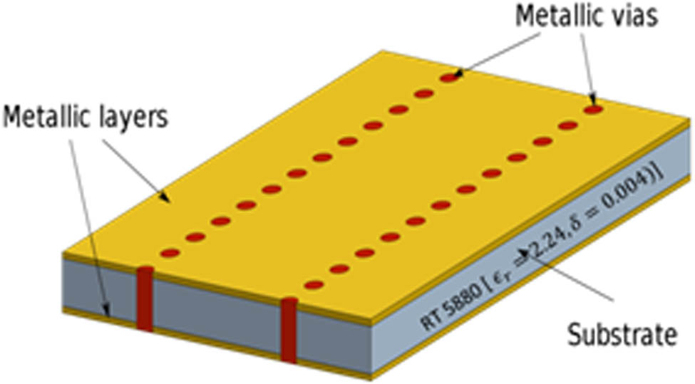
SIW structure.
2.2 Source antenna design
The LPDA antenna is chosen for its wide bandwidth, high gain, efficiency, and ease of integration. The LPDA design involves determining the scale factor, spacing factor, and the number of dipole elements. The design parameters such as the lengths, widths, and spacing between the dipole components are calculated based on the desired bandwidth and directivity. The LPDA design is optimized to achieve the desired performance metrics. The detailed analysis of LPDA design is well illustrated in previous studies [17,18]. The integration of the LPDA and SIW antennas was accomplished through a tapered connection, ensuring seamless transition and proper feeding. Transition from microstrip to waveguide is demonstrated in the literature [19,20].
2.3 Luneburg lens design
A Luneburg lens is introduced to enhance antenna gain and provide beam scanning and shaping capabilities, while reducing the overall size of the antenna. The lens design consists of different layers with specific dielectric constants and radius, as illustrated in Figure 2. The radius and permittivity of each layer are determined using mathematical equations based on the number of layers. The Luneburg lens is designed to focus the radiation pattern in the H-plane and is fabricated using a novel, low-cost, and easy technological approach. The lens is evaluated in the 60 GHz bandwidth spectrum, and its behavior is analyzed using Airex PXc 245 foam materials.

Cross-sectional view of Luneburg lens.
The different layer radii of the Luneburg (r i ) lens and the different dielectric permittivities (ε i ) of each layer can be obtained from the equations below, where N is the number of layers [8]:
3 Simulation
3.1 SIW simulation
The simulation was carried out in CST Microwave Studio with a lambda/20 mesh size. The SIW simulation involves designing and optimizing a 60 GHz SIW using Roger RT/Duroid5880 as the substrate material (ε r = 2.23, δ = 0.003, h = 0.127 mm) with copper thickness M t = 0.018 mm. The SIW transmission line, modeled using CST Microwave Studio, is shown in Figure 3 with its optimized parameter tabulated in Table 1. Figure 4 shows excellent performance with a cutoff frequency of 44 GHz.

SIW structure with transition and feed.
SIW parameters dimension
| Parameters | W siw (mm) | W trans (mm) | W 0 (mm) | L trans (mm) | P (mm) | D (mm) |
|---|---|---|---|---|---|---|
| Dimensions (mm) | 2.41 | 2.11 | 0.34 | 2 | 0.48 | 0.3 |

SIW return loss plot vs frequency.
The analysis of scattering parameters (S11, S21) demonstrates a strong match between the SIW and antenna design at 60 GHz (above 48 GHz).
3.2 LPDA simulation
In the LPDA simulation, a log periodic antenna (LPDA) design is presented. The optimized LPDA design incorporates changes in the leg values (a n , b n ) and leg spacing. The LPDA structure which shown in Figure 5 is designed to optimise the performance with a wide bandwith and directivity, and its dimensions are provided in Table 2, is based on a Roger RT/Duroid 5,880 substrate with dielectric parameters (ε r = 2.23, δ = 0.003) with a thickness of (h = 0.127 mm), which helps in reducing surface waves.

LPDA structure with dimensions.
LPDA dimensions
| Parameters | a n (mm) | b n (mm) | S n−1 (mm) | |
|---|---|---|---|---|
| n | 1 | 0.17 | 0.82 | 1.20 |
| 2 | 0.14 | 0.77 | 1.07 | |
| 3 | 0.11 | 0.77 | 0.69 | |
| 4 | 0.09 | 0.66 | 0.59 | |
| 5 | 0.07 | 0.42 | 0.49 | |
| 6 | 0.06 | 0.29 | 0.41 | |
| 7 | 0.05 | 0.23 | 0.34 | |
| 8 | 0.04 | 0.19 | 0.29 | |
| 9 | 0.03 | 0.15 | 0.24 | |
| 10 | 0.03 | 0.12 | 0.20 | |
| L (mm) | 5.58 | |||
| W (mm) | 0.34 | |||
The optimized LPDA design achieves a bandwidth of 9 GHz below −10 dB. The optimized S-parameter is plotted along with the antenna gain in Figure 6, highlighting the performance characteristics.

LPDA gain and S11 vs frequency plot.
3.3 LPDA, SIW, and Luneburg lens (system) simulation
This section focuses on the integration of the optimized LPDA and SIW components with the Luneburg lens to form a complete system. A tapered transition is introduced between the SIW and LPDA antenna to ensure a smooth connection, as shown in Figure 7. The thickness of metal on either side of the substrate is 0.127 mm. The optimized dimensions are displayed in Table 3.

Single SIW antenna with LPDA: (a) top view and (b) bottom view.
Single antenna element dimensions
| Parameters | a n (mm) | b n (mm) | S n−1 (zmm) | L n(mm) | Ltrans, n (mm) | |
|---|---|---|---|---|---|---|
| n | 1 | 0.17 | 0.65 | 0.78 | 1.4 | 2 |
| 2 | 0.14 | 0.79 | 0.96 | 4.56 | 1.95 | |
| 3 | 0.11 | 0.64 | 0.78 | 5.16 | ||
| 4 | 0.09 | 0.52 | 0.66 | |||
| 5 | 0.07 | 0.28 | 0.51 | |||
| 6 | 0.06 | 0.23 | 0.41 | |||
| 7 | 0.05 | 0.18 | 0.33 | |||
| 8 | 0.04 | 0.15 | 0.27 | |||
| 9 | 0.03 | 0.12 | 0.22 | |||
| 10 | 0.03 | 0.10 | 0.18 | |||
| L (mm) | 15.27 | |||||
| W (mm) | 4.46 | |||||
The optimized structure achieves a wide bandwidth of 20 GHz at 60 GHz, as depicted in Figure 8. Additionally, a directivity of 6.99 dB and a half-power beamwidth (HPBW) of 59° are achieved.

Antenna gain and S11 vs frequency plot.
3.4 Luneburg lens and full system simulation
Next, the simulation focuses on the Luneburg lens and the performance of the full system comprising multiple antennas. The lens design process involves optimizing the number of layers and choosing the optimal structure based on the radiation pattern, which can be seen in Figure 9 with one source element. The optimized dimensions of the lens are tabulated in Table 4. The results indicate that a six-layer lens provides a smoother radiation pattern.

Luneburg lens structure with a single feed: (a) top view and (b) side view.
Luneburg lens parameters
| Parameters | Radius (mm) | Permittivity (ε) | Loss tangent | |
|---|---|---|---|---|
| Layer number | 1 | 11.625 | 1.92 | 0.015 |
| 2 | 16.5 | 1.77 | 0.014 | |
| 3 | 20.15 | 1.62 | 0.013 | |
| 4 | 23.275 | 1.46 | 0.01 | |
| 5 | 26 | 1.31 | 0.008 | |
| 6 | 28.5 | 1.15 | 0.007 | |
| Lens thickness (h) (mm) | 3.2 | |||
| Air gap (mm) | 2.6 | |||
The optimized single antenna element with a lens is achieved with specific parameters, resulting in a directivity of 16.5 dB and a HPBW of 4.6°, as illustrated in Figure 10 at 60 GHz. Additionally, Figure 11 shows a gain of 14.5 dB, which complements the performance characteristics of the antenna element.

Far-field directivity plot.

Gain and S11 vs frequency plot.
The phase distribution of a Luneburg lens is a key characteristic that contributes to its unique focusing properties. In a Luneburg lens, the refractive index varies radially from the center to the outer surface, creating a gradient lens. The phase distribution across the lens is such that it compensates for the spherical aberration that would occur in a simple lens with a uniform refractive index.
For a Luneburg lens, the phase distribution is typically designed to be radially symmetric. The phase distribution is such that the wavefronts passing through different regions of the lens converge at the same focal point, resulting in the effective focusing of incoming waves.
The phase distribution of the Luneburg lens with different feeding angles (90°, 0°, and 45°) is shown in Figure 12.

Phase distribution. (a) 90°, (b) 0°, (c) 45°.
Expanding the system to three antenna elements, as shown in Figure 13, their behavior in the far field is examined for multiple-angle separations. The adjacent placement of the three antennas was tested with varying separation angles to achieve 3 dB overlapping. However, the results provided in Figure 14 show a version of the incomplete coverage and increased side lobe levels when setting the separation angle to be 4.5°.

Adjacent antenna structure.

Far-field plot without coverage.
To address this issue of incomplete coverage, we first propose a new idea of a vertically stacked double Luneburg lens with feed elements in the lower and upper lens concept is introduced as shown in Figure 15 with an angle separation of 9° between two feed elements in the same lens and the angle between the adjacent feed element in the lower and upper lens is 4.5°.

Doubled stacked Luneburg lens: (a) top view and (b) side view.
The optimization process focuses on determining the vertical alignment and separation distance between the lenses. The best results are obtained when the antennas are aligned in the middle, and the optimized vertical lens separation is 0.75 mm. The directivity and gain for different frequencies are analyzed, and the one-dimensional far-field pattern is observed at 60 GHz, which can be seen in Figure 16.

Far-field plot with coverage.
Additionally, the coupling between the three adjacent antenna elements was minimal and reached a value of −20 dB on the operating frequency, as shown in Figure 17.

S-parameter of three-adjacent antenna elements to show coupling effect.
Finally, the full system integration consists of 37 antenna feeds in both lenses, providing a coverage area of 170°, as shown in Figure 18. The structure of both lenses and feeds is supported using FR-3703 polyurethane foam (ε r = 1.04, tans δ = 0.00170), as seen in the same figure. The performance is evaluated in terms of directivity, gain, and overlapping. The results demonstrate a difference of ≥13 dB between the main and side lobes, achieving 3 dB overlapping as illustrated in Figures 19 and 20, with a directivity of 17 and 14.8 dB gain, respectively.

Full system doubled stacked Luneburg lens with supporting foam with complete feed: (a) top view and (b) side view.

Full system far-field directivity plot.

Full system far field gain plot.
The optimized system showed consistent performance throughout the operating frequency range with an efficiency reaching 63%, as shown in Figure 21.

Efficiency vs frequency plot.
4 Prototyping
The fabricated design of the antenna yielded promising results. Figure 22 displays the simulated structure. Due to the limitations in manufacturing capabilities in our lab, the substrate thickness was increased to 0.79 mm (h = 0.79 mm). Consequently, the feed is optimized to match the new thickness, with the optimized dimensions provided in Table 5.

Simulation structure.
Prototype feed dimensions
| Parameter | (mm) | |
|---|---|---|
| W n | 1 | 0.60 |
| 2 | 2.38 | |
| 3 | 8.00 | |
| D | 0.50 | |
| P | 0.90 | |
| L | 23.59 | |
| W | 17.00 | |
The prototype is depicted in Figure 23 with SIW and LPDA. The LPDA antenna is printed using LPKF laser and electronics PhotoMat S-103, and the S-parameter is measured using a Keysight vector network analyzer (PNAX; N5247A). The measured return loss closely matched the simulated results (55–75 GHz), as shown in Figure 24, validating the accuracy of the design and manufacturing procedures.

Prototype.

Return loss vs frequency plot of the prototype.
These findings provide strong evidence for the practical applicability of the fabricated design in this microcell technology, highlighting the effectiveness of the beam-scanning antenna in enabling precise and efficient control of electromagnetic radiation. This research contributes to the advancement of high-speed antenna networks, facilitating the development of reliable and high-performance 5G microcell technology.
A comparison of the proposed antenna with other work is given Table 6, which clearly shows that the proposed antenna achieved better performance in terms of a gain of 14.8 dB and a pattern coverage of around 170° compared with state-of-the-art antenna designs. The other works in the literature show a maximum beam scanning angle of only 120°. Also, the gain is maximum in this work. This antenna is cost-effective and easy to fabricate compared to others mentioned in the table. Due to this wide-angle scanning capability, this work is suitable for high-speed wireless communication applications.
Comparative analysis between the proposed antenna and state-of-the-art antennas
| Ref. | Frequency f (GHz) | Bandwidth (BW) | Gain (dB) | Scanning range | Efficiency η (%) |
|---|---|---|---|---|---|
| [21] | 60 | 58/67 | 11.7 | 21° (38° to 7°) | 90 |
| [22] | 60 | 50/75 | 14.2 | 49° (−9° to 40°) | 75 |
| [23] | 60 | 52/63 | 11.4 | 9° (12° to 3°) | — |
| [24] | 60 | 55/65 | 14.5 | 120° (−72° to 48°) | 88.2 |
| Proposed | 60 | 54/67 | 14.8 | 170° (−85° to 85°) | 63 |
5 Conclusion
This study presents the design and simulation of a beam-scanning antenna for future high-speed short-range communication systems operating at 60 GHz. The system incorporates an SIW, an LPDA antenna, and a Luneburg lens. The optimized SIW and LPDA antenna achieve directivities of 5.95 and 6.99 dB at 60 GHz, respectively, with improved bandwidth and radiation patterns. The addition of a vertically stacked double Luneburg lens enhances the system’s directivity to 17 dB. Simulation results demonstrate wide-angle beam scanning and good radiation efficiency, making the antenna suitable for power-efficient future high-speed applications. The integrated system comprises 37 antenna elements achieving around 170° coverage with beam-scanning capability. Hence, it offers a promising candidate for real-world implementation in high-frequency 60 GHz communication systems.
Acknowledgements
This work was supported by the National Plan for Science, Technology and Innovation (MAARIFAH) and King Abdulaziz City for Science and Technology, Saudi Arabia, under Award 13-ELE1184-02-R. The authors are grateful for the reviewer’s valuable comments that improved the manuscript.
-
Funding information: This work was supported by the National Plan for Science, Technology and Innovation (MAARIFAH) and King Abdulaziz City for Science and Technology, Saudi Arabia, under Award 13-ELE1184-02-R.
-
Author contributions: All authors have accepted responsibility for the entire content of this manuscript and consented to its submission to the journal, reviewed all the results, and approved the final version of the manuscript. Ahmed Alhumaidan, Meshal Bahammam, and Tariq Alrashied did all the simulation and manufacturing of the work. Hamsakutty Vettikalladi and Majeed Alkanhal did the overall supervision of the work and manuscript preparation.
-
Conflict of interest: Authors state no conflict of interest.
-
Data availability statement: All data generated or analyzed during this study are included in this published article.
References
[1] Lawrence NP, Ng BW, Hansen HJ, Abbott D. 5G terrestrial networks: Mobility and coverage – Solution in three dimensions. IEEE Access. 2017;5:8064–93. 10.1109/ACCESS.2017.2693375.Search in Google Scholar
[2] Rangan S, Rappaport TS, Erkip E. Millimeter-wave cellular wireless networks: Potentials and challenges. Proc IEEE. 2014;102(3):366–85. 10.1109/JPROC.2014.2299397.Search in Google Scholar
[3] Wang HF, Wang ZB, Wu ZH, Zhang YR. Beam-scanning lens antenna based on elliptical paraboloid phase distribution metasurfaces. IEEE Antennas Wirel Propag Lett. 2019;18(8):1562–6. 10.1109/LAWP.2019.2922695.Search in Google Scholar
[4] Vettikalladi H, Lafond O, Himdi M. High-efficient and high-gain superstrate antenna for 60-GHz indoor communication. IEEE Antennas Wirel Propag Lett. 2009;8:1422–5. 10.1109/LAWP.2010.2040570.Search in Google Scholar
[5] Das P, Singh AK. Gain enhancement of millimeter wave antenna by ultra-thin radial phase gradient metasurface for 5G applications. IETE J Res. 2023;69:2400–8. 10.1080/03772063.2023.2191998.Search in Google Scholar
[6] Bor J, Lafond O, Merlet H, Le Bars P, Himdi M. Foam based Luneburg lens antenna at 60 GHz. Prog Electromagn Res Lett. 2014;44:1–7. 10.2528/PIERL13092405.Search in Google Scholar
[7] Das P, Singh AK, Mandal K. Beam-steering of millimeter wave antenna using linear phase gradient metalens for 5G applications. Int J RF Microw Comput Eng. 2022;32(12):e23459. 10.1002/mmce.23459.Search in Google Scholar
[8] Fuchs B, Le Coq L, Lafond O, Rondineau S, Himdi M. Design optimization of multishell Luneburg lenses. IEEE Trans Antennas Propag. 2007;55(2):283–9. 10.1109/TAP.2006.889849.Search in Google Scholar
[9] Che X, Gao J, Li Z. 3-D printed high-gain elliptic flat Luneburg lens. Results Phys. 2024;57:1–9. 10.1016/j.rinp.2024.107350.Search in Google Scholar
[10] Balanis CA. Antenna theory: analysis and design. 3rd edn. NJ: John Wiley; 2005.Search in Google Scholar
[11] Wu K, Deslandes D, Cassivi Y. The substrate integrated circuits - a new concept for high-frequency electronics and optoelectronics. 6th International Conference on Telecommunications in Modern Satellite, Cable and Broadcasting Service. Telsiks; 2003. p. P-III. 10.1109/TELSKS.2003.1246173.Search in Google Scholar
[12] Entesari K, Saghati AP, Sekar V, Armendariz M. Tunable SIW structures: antennas, VCOs, and filters. IEEE Microw Mag. 2015;16(5):34–54. 10.1109/MMM.2015.2408273.Search in Google Scholar
[13] Wu K. Integration and interconnect techniques of planar and non-planar structures for microwave and millimeter-wave circuits – current status and future trend. 2001 Asia-Pacific Microw Conference. 2001. p. 411–6. 10.1109/APMC.2001.985398.Search in Google Scholar
[14] Yan L, Hong W, Wu K, Cui TJ. Investigations on the propagation characteristics of the substrate integrated waveguide based on the method of lines. Microwaves, Antennas Propag, IEE Proc. 2005;152:35–42. 10.1049/IP-MAP:20040726.Search in Google Scholar
[15] He F. Innovative microwave and millimetre-wave components and sub-systems based on substrate integration technology. Ph.D. thesis. Montreal, Canada: École Polytechnique de Montréal; 2011. https://publications.polymtl.ca/524/.Search in Google Scholar
[16] Che W, Deng K, Wang D, Chow Y. Analytical equivalence between substrate-integrated waveguide and rectangular waveguide. IET Microw Antennas Propag. 2008;2:35–41. 10.1049/IET-MAP:20060283.Search in Google Scholar
[17] Campbell C, Traboulay I, Suthers M, Kneve H. Design of a stripline log-periodic dipole antenna. IEEE Trans Antennas Propag. 1977;25(5):718–21. 10.1109/TAP.1977.1141653.Search in Google Scholar
[18] Carrel R. The design of log-periodic dipole antennas. 1958 IRE International Convention Record. 1966. p. 61–75. 10.1109/IRECON.1961.1151016.Search in Google Scholar
[19] Deslandes D, Wu K. Integrated microstrip and rectangular waveguide in planar form. IEEE Microw Wirel Compon Lett. 2001;11(2):68–70.10.1109/7260.914305Search in Google Scholar
[20] Aqlan B, Vettikalladi H, Alkanhal MA. Millimeter wave antenna with frequency selective surface (FSS) for 79 GHz automotive radar applications. Int J Microw Wirel Technol. 2016;9(2):281–90. 10.1017/S1759078716000027.Search in Google Scholar
[21] Jackson DR, Caloz C, Itoh T. Leaky-wave antennas. Proc IEEE. 2012;100(7):2194–206. 10.1109/JPROC.2012.2187410.Search in Google Scholar
[22] Bai X, Qu SW, Ng KB, Chan CH. Sinusoidally modulated leaky wave antenna for millimeter – wave application. IEEE Trans Antennas Propag. 2016;64(3):849–55. 10.1109/TAP.2015.2513089.Search in Google Scholar
[23] Jackson DR, Oliner AA, Balanis CA. Leaky-wave antennas. Modern antenna handbook. Hoboken, NJ, USA: Wiley; 2007. p. 325–67. 10.1002/9780470294154.ch7.Search in Google Scholar
[24] Sarkar A, Lim S. 60 GHz compact larger beam scanning range PCB leaky-wave antenna using HMSIW for millimeter-wave applications. IEEE Trans Antennas Propag. 2020;68(8):5816–26. 10.1109/TAP.2020.2983.Search in Google Scholar
© 2025 the author(s), published by De Gruyter
This work is licensed under the Creative Commons Attribution 4.0 International License.
Articles in the same Issue
- Research Articles
- Modification of polymers to synthesize thermo-salt-resistant stabilizers of drilling fluids
- Study of the electronic stopping power of proton in different materials according to the Bohr and Bethe theories
- AI-driven UAV system for autonomous vehicle tracking and license plate recognition
- Enhancement of the output power of a small horizontal axis wind turbine based on the optimization approach
- Design of a vertically stacked double Luneburg lens-based beam-scanning antenna at 60 GHz
- Synergistic effect of nano-silica, steel slag, and waste glass on the microstructure, electrical resistivity, and strength of ultra-high-performance concrete
- Expert evaluation of attachments (caps) for orthopaedic equipment dedicated to pedestrian road users
- Performance and rheological characteristics of hot mix asphalt modified with melamine nanopowder polymer
- Second-order design of GNSS networks with different constraints using particle swarm optimization and genetic algorithms
- Impact of including a slab effect into a 2D RC frame on the seismic fragility assessment: A comparative study
- Analytical and numerical analysis of heat transfer from radial extended surface
- Comprehensive investigation of corrosion resistance of magnesium–titanium, aluminum, and aluminum–vanadium alloys in dilute electrolytes under zero-applied potential conditions
- Performance analysis of a novel design of an engine piston for a single cylinder
- Modeling performance of different sustainable self-compacting concrete pavement types utilizing various sample geometries
- The behavior of minors and road safety – case study of Poland
- The role of universities in efforts to increase the added value of recycled bucket tooth products through product design methods
- Adopting activated carbons on the PET depolymerization for purifying r-TPA
- Urban transportation challenges: Analysis and the mitigation strategies for road accidents, noise pollution and environmental impacts
- Enhancing the wear resistance and coefficient of friction of composite marine journal bearings utilizing nano-WC particles
- Sustainable bio-nanocomposite from lignocellulose nanofibers and HDPE for knee biomechanics: A tribological and mechanical properties study
- Effects of staggered transverse zigzag baffles and Al2O3–Cu hybrid nanofluid flow in a channel on thermofluid flow characteristics
- Mathematical modelling of Darcy–Forchheimer MHD Williamson nanofluid flow above a stretching/shrinking surface with slip conditions
- Energy efficiency and length modification of stilling basins with variable Baffle and chute block designs: A case study of the Fewa hydroelectric project
- Renewable-integrated power conversion architecture for urban heavy rail systems using bidirectional VSC and MPPT-controlled PV arrays as an auxiliary power source
- Exploitation of landfill gas vs refuse-derived fuel with landfill gas for electrical power generation in Basrah City/South of Iraq
- Two-phase numerical simulations of motile microorganisms in a 3D non-Newtonian nanofluid flow induced by chemical processes
- Sustainable cocoon waste epoxy composite solutions: Novel approach based on the deformation model using finite element analysis to determine Poisson’s ratio
- Impact and abrasion behavior of roller compacted concrete reinforced with different types of fibers
- Architectural design and its impact on daylighting in Gayo highland traditional mosques
- Structural and functional enhancement of Ni–Ti–Cu shape memory alloys via combined powder metallurgy techniques
- Design of an operational matrix method based on Haar wavelets and evolutionary algorithm for time-fractional advection–diffusion equations
- Design and optimization of a modified straight-tapered Vivaldi antenna using ANN for GPR system
- Analysis of operations of the antiresonance vibration mill of a circular trajectory of chamber vibrations
- Functions of changes in the mechanical properties of reinforcing steel under corrosive conditions
- Enhanced PAPR reduction in NOMA systems using modified SLM and PTS techniques for power-efficient 5G and beyond networks
- Hybrid mechanics-informed machine learning models for predicting mechanical failure in graphene sponge: a low-data strategy for mechanical engineering applications
- Design of shafts of a two-piece chain conveyor as a part of a modification of a mobile working machine
- Review Articles
- A modified adhesion evaluation method between asphalt and aggregate based on a pull off test and image processing
- Architectural practice process and artificial intelligence – an evolving practice
- 10.1515/eng-2025-0148
- Special Issue: 51st KKBN - Part II
- The influence of storing mineral wool on its thermal conductivity in an open space
- Use of nondestructive test methods to determine the thickness and compressive strength of unilaterally accessible concrete components of building
- Use of modeling, BIM technology, and virtual reality in nondestructive testing and inventory, using the example of the Trzonolinowiec
- Tunable terahertz metasurface based on a modified Jerusalem cross for thin dielectric film evaluation
- Integration of SEM and acoustic emission methods in non-destructive evaluation of fiber–cement boards exposed to high temperatures
- Non-destructive method of characterizing nitrided layers in the 42CrMo4 steel using the amplitude-frequency technique of eddy currents
- Evaluation of braze welded joints using the ultrasonic method
- Analysis of the potential use of the passive magnetic method for detecting defects in welded joints made of X2CrNiMo17-12-2 steel
- Analysis of the possibility of applying a residual magnetic field for lack of fusion detection in welded joints of S235JR steel
- Eddy current methodology in the non-direct measurement of martensite during plastic deformation of SS316L
- Methodology for diagnosing hydraulic oil in production machines with the additional use of microfiltration
- Special Issue: IETAS 2024 - Part II
- Enhancing communication with elderly and stroke patients based on sign-gesture translation via audio-visual avatars
- Optimizing wireless charging for electric vehicles via a novel coil design and artificial intelligence techniques
- Evaluation of moisture damage for warm mix asphalt (WMA) containing reclaimed asphalt pavement (RAP)
- Comparative CFD case study on forced convection: Analysis of constant vs variable air properties in channel flow
- Evaluating sustainable indicators for urban street network: Al-Najaf network as a case study
- Node failure in self-organized sensor networks
- Comprehensive assessment of side friction impacts on urban traffic flow: A case study of Hilla City, Iraq
- Design a system to transfer alternating electric current using six channels of laser as an embedding and transmitting source
- Security and surveillance application in 3D modeling of a smart city: Kirkuk city as a case study
- Modified biochar derived from sewage sludge for purification of lead-contaminated water
- The future of space colonisation: Architectural considerations
- Design of a Tri-band Reconfigurable Antenna Using Metamaterials for IoT Applications
- Special Issue: AESMT-7 - Part II
- Experimental study on behavior of hybrid columns by using SIFCON under eccentric load
- Special Issue: ICESTA-2024 and ICCEEAS-2024
- A selective recovery of zinc and manganese from the spent primary battery black mass as zinc hydroxide and manganese carbonate
- Special Issue: REMO 2025 and BUDIN 2025
- Predictive modeling coupled with wireless sensor networks for sustainable marine ecosystem management using real-time remote monitoring of water quality
- Management strategies for refurbishment projects: A case study of an industrial heritage building
- Structural evaluation of historical masonry walls utilizing non-destructive techniques – Comprehensive analysis