Two-phase numerical simulations of motile microorganisms in a 3D non-Newtonian nanofluid flow induced by chemical processes
-
Syed Modassir Hussain
 ,
Adebowale Martins Obalalu
,
Adebowale Martins Obalalu

Abstract
The growing demand for efficient thermal management in advanced engineering and biomedical applications underscores the importance of exploring nanofluid-based systems. This study aims to develop and analyze a three-dimensional mathematical model of electrically conducting Sutterby nanofluids, incorporating bio-convection phenomena with Hall effects, activation energy, and chemical reactions. The flow is considered steady, incompressible, and influenced by electromagnetic fields, with entropy generation used as a measure of system performance. The governing equations are reduced to a set of coupled nonlinear differential equations through similarity transformations and solved numerically using the Chebyshev collocation spectral method. The results demonstrate that increasing the Lewis number significantly reduces the mass concentration, while a higher Biot number enhances the distribution of microorganisms. The novel aspect of this work lies in integrating entropy optimization with multi-physical effects in Sutterby nanofluids, thereby providing deeper insights into thermal efficiency and irreversibility in bio-convective systems. These findings contribute to advancing energy-efficient designs and optimizing nanofluid-based thermal transport technologies for industrial and biomedical applications.
1 Introduction
Thermal radiation is a process in which energy is emitted in the form of electromagnetic waves due to the temperature of a body. Unlike conduction and convection, it does not require a medium for transfer and can occur even in a vacuum. All objects with a temperature above absolute zero emit thermal radiation, with the intensity and wavelength distribution depending on their temperature and surface properties. This phenomenon plays a crucial role in heat transfer processes in engineering, astrophysics, climate science, and various industrial applications, influencing energy balance, thermal management, and radiative cooling mechanisms. Ramzan et al. [1] examined the influence of non-linear thermal radiation concerning the movement of energy and mass within a fluid augmented by nanoparticles and comprising motile gyrotactic microbes. Muhammad et al. [2] conducted a study on 3D hydromagnetic swirling flow incorporating nanomaterials, employing kerosene oil, motor oil, and water as base fluids to suspend carbon nanotubes. The investigation, performed under the influence of non-linear thermal radiation, focused on the behavior of the flow over a deformable surface using the Casson fluid model. The behavior of non-linear radiation in a Newtonian fluid over an extending vertical sheet was examined by Gul et al. [3]. This analysis has significance for a number of organizations, such as gas turbines, nuclear power plants, solar energy systems, electronics cooling, paper manufacturing, and polymer execution. Sreedevi et al. [4] deliberated the mass and heat transfer features of nanofluids consisting of TiO2–water and Al2O3–water, as well as nonlinear thermal radiation on mixed convective fluid flow. Hayat et al. [5] studied the peristaltic motion of the Sutterby fluid with a sensitive temperature thermal conductivity effect of a slanted magnetic field in curved geometries. Joule heating, non-linear thermal radiation, heat production, and viscous dissipation were all considered in the energy equation. Khan et al. [6] assessed the steady and 2D boundary layer hydromagnetic flow surrounded by thin needle that was moving horizontally while generating non-linear heat radiation. In the energy equation, radiative heat transfer was modeled using the Rosseland approximation, assuming a laminar and viscous flow. The nanofluid was titanium dioxide (TiO2), while the base fluid was water. Iftikhar et al. [7] examined how hybrid nanofluid convection in a cavity was affected by a heated fin, non-linear radiation, and nanoparticle fractions (Cu and Ag) in ethylene glycol. Irreversibility and heat flow were examined using the Bejan number and Bejan heat lines, and thermodynamics was used to evaluate the interruption of energy transfer. Irreversibility analysis of a two-phase non-Newtonian nanofluid model induced by converging/diverging channels with heat source/sink and viscous dissipation effects was examined by Gasmi et al. [8]. Analysis of advanced cooling strategies for rocket engines conveying ternary hybrid nanofluids with second slip conditions and melting heat transfer was examined by Gasmi et al. [9]. Dissipative heat transfer in blood-based ternary hybrid nanofluids through a parallel channel with entropy optimization was examined by Wang et al. [10]. Irreversibility analysis of cross‐flow in an Eyring–Powell nanofluid over a permeable deformable sheet with Lorentz forces was examined by Khan et al. [11]. Dynamic features of heat transfer in a square enclosure induced by an adiabatic rotating circular cylinder with double‐diffusive buoyancy forces were examined by Olayemi et al. [12]. The influence of thermal radiation and electromagnetic characteristics of micropolar ternary hybrid nanofluid flow over a slender surface was examined by Obalalu et al. [13]. Dynamics of second-law analysis and thermal performance in solar-powered tractors using a parabolic trough solar collector filled with tri-hybrid nanofluid were examined by Ogunsanwo et al. [14].
The Hall effect is the production of a voltage difference (called the Hall voltage) across an electrical conductor when a magnetic field is applied perpendicular to the current flow. It was discovered by Edwin Hall in 1879. When an electric current passes through a conductor placed in a magnetic field, the moving charge carriers (electrons or holes) experience a force due to the field, causing them to accumulate on one side of the material. This accumulation creates a measurable potential difference, which provides valuable information about the type of charge carriers, their density, and mobility. The Hall effect is widely used in physics and engineering, with applications in magnetic field sensing, position and speed detection, semiconductor characterization, and current measurement devices. Hall effect sensors are used in proximity, velocity, and location detecting systems [15–18]. Karsenty [19] examined the main technologies that are based on both contemporary and conventional Hall effects. Sections on macro-, micro-, and nanoscales and quantum-based elements and circuit implementations were included in the study. Engineers and scientists have long sought to integrate Hall effect equipment into small networks in order to prepare possible sophisticated features like elevated speed switches, especially in nanoscale technology, since these devices use current and magnetism as inputs to generate voltage as an output. Du et al. [20] summarized the recent developments in the nonlinear Hall effect. Unresolved problems, possible spectroscopic and device applications of the nonlinear Hall effect, and assumptions about other nonlinear transport-related phenomena are discussed. Hu et al. [21] showed that restriction can be overcome by taking advantage of the magnetized rotating Hall effect in anti-magnets whose magnetic symmetry creates polarization aligned to its direction. Unlike conventional devices, this switching is perfect for low-power applications because it does not require an ambient magnetization and operates at a notably reduced current density.
When current is transmitted through a conductor, the capacitance of the materials causes a phenomenon known as the Joule dissipation effect, in which electromagnetic energy is transformed into thermal energy. Resistive parts like cables, boilers, and power systems frequently exhibit this effect was examined by El-Amin [22]. Chen [23] evaluated the combined impact of Joule heating and viscous dissipation on heat transmission and momentum in hydromagnetic flow through an elongated sheet. The study also took into account how flow regime and rate of heat transfer are affected by surface blowing/suction, thermal energy, and free convection. Mishra and Kumar [24] examined how the internal friction and Joule heating affected the behavior and thermal characteristics of a magnetized Ag/H2O (silver–water) nanofluid around an expanding cylinder while considering the partial-slip boundary conditions. The 2D hydromagnetic flow of an incompressible nanofluid toward a perforated extended sheet was examined by Khan et al. [25] with regard to slip conditions and Joule heating. The dispersion MHD fluid flow across an extending inclined plane was studied by Jayanthi and Niranjan [26], considering heat radiation, joule dissipation, and activation energy. Such effects are important in fields like mathematical computing, automotive engineering, and cosmology, and commonly arise in systems with aligned configurations. A thorough analysis of hybridized nanomaterials across a variable sheet under the impact of viscous dissipation effects and joule heating has been carried out by specialists. Water was utilized as the standard fluid in the hybrid nanofluid, and various nanomaterials had a synergistic effect on the thermo-transport processes [27–31].
The Sutterby fluid model is a non-Newtonian fluid model used to describe the flow behavior of shear-thinning and shear-thickening fluids, particularly those exhibiting exponential dependence of viscosity on the shear rate. Unlike Newtonian fluids, whose viscosity remains constant, Sutterby fluids display a viscosity that decreases (shear-thinning) or increases (shear-thickening) with applied shear stress. This model is especially useful for characterizing complex fluids such as polymer solutions, biological fluids, and certain industrial suspensions, where conventional power-law or Bingham models may not accurately capture the exponential viscosity variation. The Sutterby model provides a more flexible representation by incorporating parameters that control the degree of shear dependency, making it important in rheology, biomedical flows, and engineering applications involving lubricants, slurries, and nanofluids. This type of flow is commonly evaluated in projects like electrical power systems, healthcare equipment, and industrial use, with special emphasis on factors like transferring heat and the influence of external forces like electromagnetism or surface extension [32–34]. Khan et al. [35] provided an examination of how stratification processes affect the Sutterby nanofluid’s asymmetric radiative flow. It is also mentioned that the efficiency of heat transport is decreased by higher thermal stratification. Additionally, shear-thinning and shear-thickening solution characteristics are assessed using the Sutterby fluid framework. This study is especially pertinent to polymer melts and advanced polymer solutions. Khan et al. [36] used NARX (nonlinear autoregressive exogenous networks) optimized by the LMT (Levenberg-Marquardt back-propagation technique) to create the foundational mathematical concepts for the Sutterby nanofluid model in a transmissive medium. Pasha et al. [37] studied the dual diffusive flow of Sutterby nanoliquids under magnetic influence in a constrained squeezing environment. Dual stratification or changeable thermal and solutal restrictions were taken into account while modeling the convective flow. While mass transfer was examined in the context of a chemical reaction, radiative heat transfer was included in the thermal study along with convective heating.
Numerical simulations of bio‐convection radiative heat transport flow of an MHD Carreau nanofluid were study by Irfan and Muhammad [38]. Modeling heat‐mass transport for an MHD bio‐convection Carreau nanofluid with Joule heating, containing both gyrotactic microbes and nanoparticles diffusion, was studied by Irfan et al. [39]. The thermal performance of Joule heating in radiative Eyring–Powell nanofluid with Arrhenius activation energy and gyrotactic motile microorganisms was evaluated by Ali and Irfan [40]. The study of gyrotactic motile microorganisms in a Powell–Eyring nanofluid with non-Fourier and non-Fick’s theories was conducted by Ali and Irfan [41]. A numerical study of nonlinear thermal radiation and Joule heating on an MHD bioconvection Carreau nanofluid with gyrotactic microorganisms was conducted by Irfan et al. [42]. Melting rheology in chemically reactive flow of a dual stratified Eyring–Powell nanoliquid due to a stretching sheet of varied thicknesses was studied by Javed et al. [43]. The phenomena of thermo-solutal time relaxation in a mixed convection Carreau fluid with heat sink/source were studied by Irfan et al. [44]. Nonlinear mixed convection dynamics of microorganisms in tetrahydro-metamaterial systems and machine learning models for thermal-biological interface control were studied by Mingliang et al. [45]. Gyrotactic microorganisms in the pharmacokinetics of electrically conducted nanofluid over a stretching sheet and complex algorithmic models were studied by Amjad et al. [46]. Numerical analysis of unsteady flow of three-dimensional Williamson fluid-particle suspension with MHD and nonlinear thermal radiations was studied by Bibi et al. [47]. Analysis of thermal radiation in magneto-hydrodynamic motile gyrotactic micro-organisms flow comprising tiny nanoparticles toward a nonlinear surface with velocity slip was performed by Majeed et al. [48]. Parametric optimization of entropy generation in a hybrid nanofluid in a contracting/expanding channel using the analysis of variance and response surface methodology was studied by Zeeshan et al. [49]. Optimization of bioconvective heat transfer with MHD Eyring–Powell nanofluids containing motile microorganisms with viscosity variability and porous media in ciliated microchannels was conducted by Mehboob et al. [50]. Thermally induced cilia flow of a Prandtl nanofluid under the influence of electroosmotic effects with boundary slip was studied by Sait et al. [51]. Analysis of nonlinear complex heat transfer MHD flow of a Jeffrey nanofluid over an exponentially stretching sheet via three-phase artificial intelligence and machine learning techniques was performed by Zeeshan et al. [52]. The effects of MHD and temperature-dependent viscosity on the flow of non-Newtonian nanofluid in a pipe and analytical solutions were studied by Ellahi [53]. Parametric optimization of entropy generation in a hybrid nanofluid in a contracting/expanding channel using the analysis of variance and response surface methodology was conducted by Zeeshan et al. [54].
Heat transfer and mass transport play critical roles in various industrial and engineering processes, but achieving optimal thermal efficiency while minimizing entropy generation remains a significant challenge. Therefore, the aim of this study is to investigate the thermal transport characteristics of Sutterby nanofluid flow integrated with bio-convection, and to address key factors such as gyrotactic microorganisms, Hall effects, and activation energy. By formulating a comprehensive three-dimensional mathematical model, this research aims to explore the optimization of entropy-driven mechanisms within chemically reactive systems. Utilizing the Chebyshev collocation spectral method (CCSM) for numerical solutions, this study examines the effects of thermophysical parameters on thermal efficiency and entropy generation. The findings offer valuable insights into enhancing the performance of nanofluid-based bio-convection systems, contributing to the development of energy-efficient technologies in industrial and biomedical applications.
2 Mathematical framework
Mathematical modeling of the 3D convective thermal transport performance of an incompressible Sutterby nanofluid, characterized via steady fluid flow properties is presented here.
As displayed in Figure 1a, the fluid moves over a stretching surface, where the velocity components are linearly defined as
Nanoparticle diffusion at the boundary is expected to be negligible, as the fluid flow is restricted to the region where
The micropolar nanofluid framework accounts for the effects of the Hall current, where the electric current is symbolized as
The micropolar nanofluid’s behavior is influenced by the Hall current, which arises due to the interaction between the electrically conductive fluids and the applied strong magnetic field. Consequently, this phenomenon alters the micropolar nanofluid movement, transforming it into a three-dimensional flow. This modification enhances the force along the
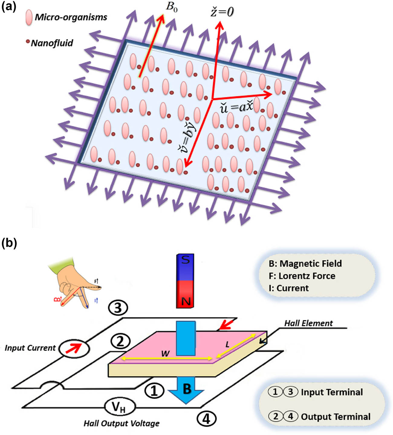
(a) Physical sketch of the problem. (b) Hall effect sensor diagram.
In its generalized framework, the expression for Ohm’s law incorporating the Hall effect can be written as [32,55]
Here, the current density is (
Taking into account the above considerations, the continuity equation for mass conservation, momentum equation, and energy equation for heat transfer are [55–57] as follows:
subjected to
In addition, the mathematical symbols or notations used in the above equations are defined in Table 1 while the equation (6) can be rewritten as follows
Symbols and descriptions
| Symbol | Description |
|---|---|
|
|
Electric field intensity |
|
|
Velocity components |
|
|
Electron collision time |
|
|
Electrical conductivity |
|
|
Electron oscillation frequency |
|
|
Electron charge |
|
|
Electron number density |
|
|
Electron pressure |
|
|
Magnetic field strength |
|
|
Components of the current density |
|
|
Hall parameter |
|
|
Permeability of the medium |
|
|
Density |
|
|
Dynamic viscosity |
|
|
Concentration of the nanoparticles |
|
|
Brownian diffusion coefficient |
|
|
Current density vector |
|
|
Thermophoretic diffusion coefficient |
|
|
Temperature |
|
|
Ambient concentration |
|
|
Ambient temperature |
|
|
Motile microorganism concentration |
|
|
Diffusion coefficient of motile microorganisms |
The similarity transformations are as follows [56]:
Using the similarity variable (13), the subsequent equation is established as follows:
The boundary conditions are as follows:
Here, the magnetic parameter
3 Gradients
The gradients of our existing problem is defined as [17,21,30]:
In the non-dimensional form, we have
4 Thermodynamic irreversibility
The investigation into entropy within fluid dynamics primarily stems from the inherent irreversibility of heat transfer, energy dissipation, and other characteristics governed by the second law of thermodynamics. The entropy generation is characterized as
In the non-dimensional form, we obtain
Here, the temperature ratio
5 Solution methodologies
5.1 CCSM
The CCSM is a powerful numerical approach for solving boundary value problems involving complex nonlinear differential equations. The following outlines a detailed step-by-step process for applying the CCSM to the specified equations. Chebyshev polynomials
where
Here,
Using the Chebyshev differentiation matrix
Applying the boundary conditions in Chebyshev form, we have at
The shifted Chebyshev polynomial is utilized to identify the suitable collocation points. The calculation of the Chebyshev coefficients
5.2 Validation of the results
Table 2 presents the comparison of microorganism density for different values of the Lewis number (Le) at various bioconvection parameters (Lb) and Peclet numbers (Pe).
Comparison of the microorganism density for varying Lewis numbers (Le) at different values of Lb and Pe
| Lb | Pe | Present work | Result of Jameel et al. [58] |
|---|---|---|---|
| 0.1 | 0.1 | 0.2179759 | 0.2179759 |
| 0.2 | 0.2794024 | 0.2794024 | |
| 0.3 | 0.1 | 0.331229 | 0.331229 |
| 0.1 | 0.2179759 | 0.2179759 | |
| 0.2 | 0.1979172 | 0.1979172 | |
| 0.3 | 0.1787575 | 0.1787575 |
6 Interpretation of the results
In this section, our primary objective is to examine the physical impact of the numerical model using graphical representations. Table 3 presents the variation in skin friction coefficients (
Numerical outcome of skin friction coefficients
|
|
|
|
|
|
|
|---|---|---|---|---|---|
| 0.1 | 0.1 | 0.1 | 0.1 | −1.045678 | 0.052314 |
| 0.3 | 0.1 | 0.1 | 0.1 | −1.315432 | 0.212678 |
| 0.5 | 0.1 | 0.1 | 0.1 | −1.045678 | 0.345678 |
| 0.1 | 0.3 | 0.1 | 0.1 | −1.174563 | 0.052314 |
| 0.1 | 0.5 | 0.1 | 0.1 | −1.342678 | 0.028976 |
| 0.1 | 0.7 | 0.1 | 0.1 | −1.045678 | 0.009843 |
| 0.1 | 0.1 | 0.5 | 0.1 | −1.093452 | 0.052314 |
| 0.1 | 0.1 | 0.7 | 0.1 | −1.125678 | −0.025678 |
| 0.1 | 0.1 | 0.1 | 0.1 | −1.045678 | −0.105432 |
| 0.1 | 0.1 | 0.1 | 0.3 | −1.045678 | 0.052314 |
| 0.1 | 0.5 | 0.1 | 0.5 | −0.723456 | 0.018765 |
| 0.3 | 0.1 | 0.1 | 0.5 | −0.487654 | 0.002134 |
Figure 2(a) and (b) shows the influence of the porosity parameter
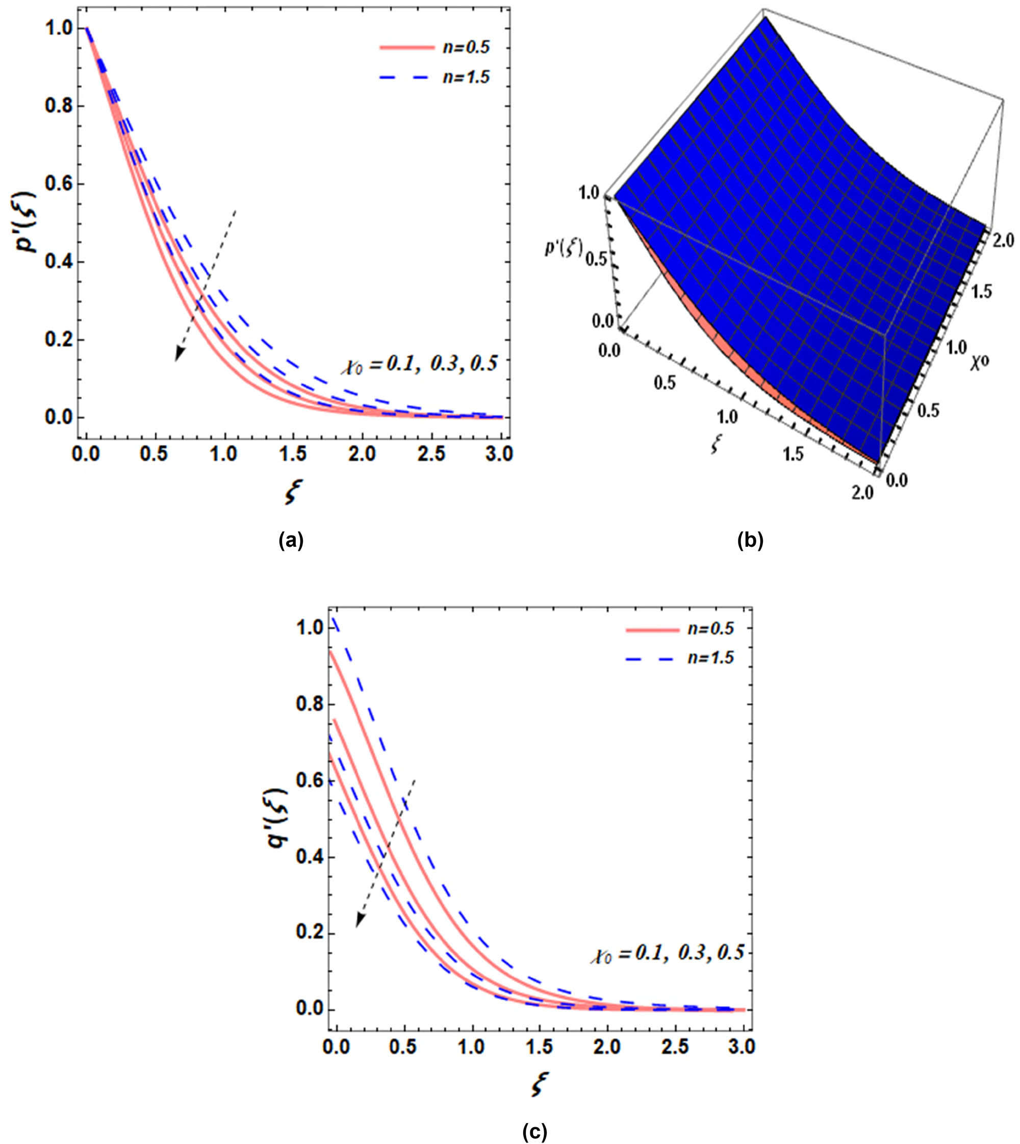
(a) Effect of
Magnetic field (M): Figure 3a–c shows the impact of the parameter M on the velocity profile in the x and y directions, respectively. In Figure 3a and c, both velocity profiles decline as the value of the magnetic field (M) increases. The fluid, being electrically conductive, experiences motion alterations due to the Lorentz force generated by its interaction with magnetic fields. An increase in the magnetic parameter strengthens interaction forces, which reduces the fluid flow speed. Fluid conductance produces lower velocities through its collision with magnetic fields during magnetic field operations. The magnetic parameter helps to analyze the proportions between magnetic forces and fluid viscous forces. An increase in the magnetic parameter causes the whole system to experience decreased fluid motion velocities. Investigation on fluid particle magnetic forces provides insight into the relationship between magnetic parameters and p′(ξ). As the M strength increases, the opposing magnetic forces intensify, restricting the particle movement and leading to a reduction in velocity. Physically, the magnetic field serves to enhance cooling operations in these cooling fluids by simultaneously controlling turbulent fluid patterns. The power generator design through magnetohydrodynamic methodology depends on the dual magnetic field effects because precise operational resistance and efficiency control are necessary for maximum power efficiency. Furthermore, q′(ξ) shows a diminishing trend in velocity with increasing magnetic field.
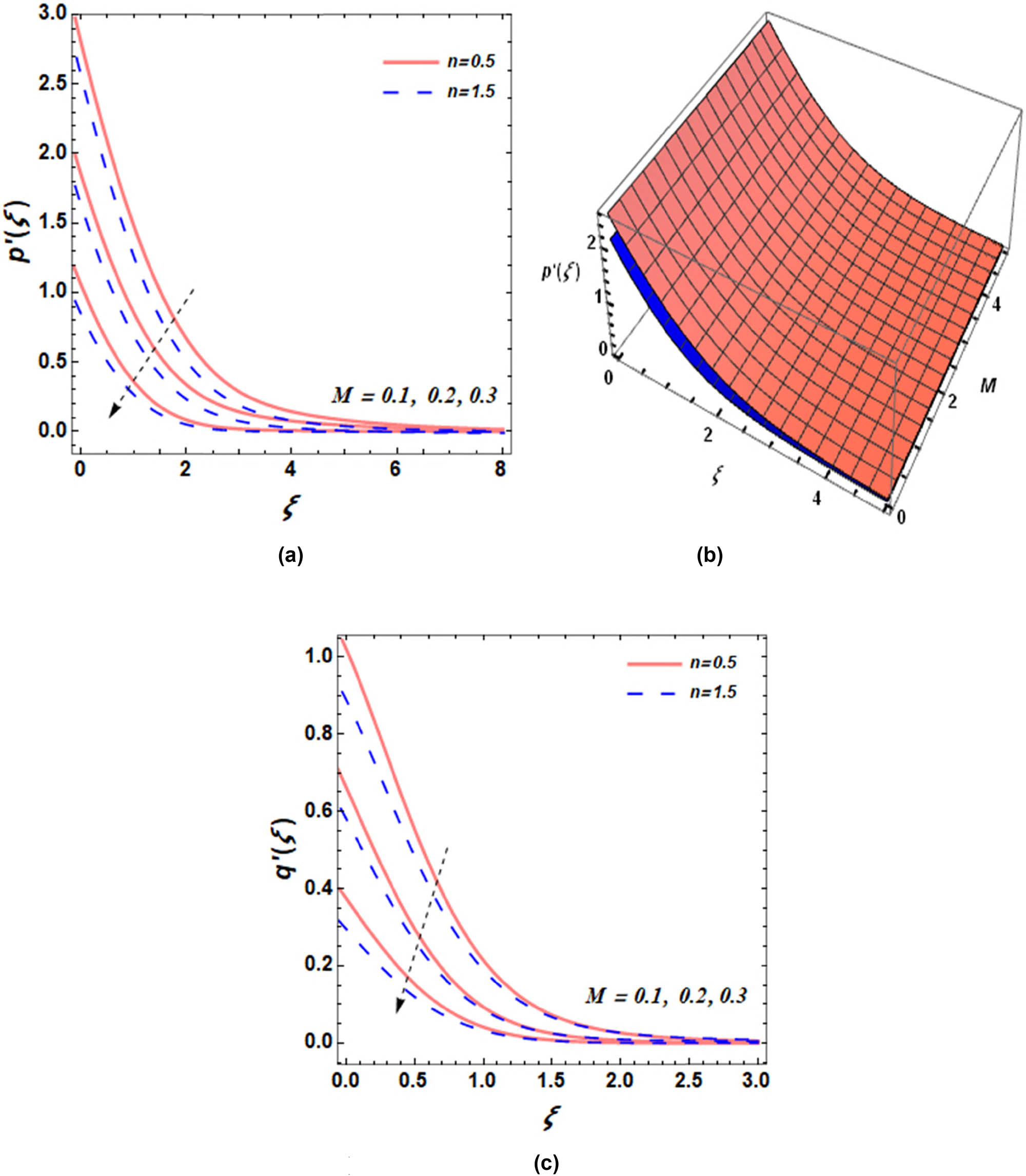
(a) Effect of M on
The magnetic parameter and thermal stratified variable: The temperature distribution and the magnetic parameter serve as an analytical tool to quantify the influence of magnetic fields on the development of thermal patterns in mechanical systems. Figure 4a and b shows that increased magnetic values produce particular temperature distribution patterns in systems for the 2D and 3D corresponding plots. A stronger magnetic field creates several instances of heat transfer suppression because magnetic fields tend to decrease fluid convective motions that transport heat. The thermal conductivity increases when the magnetic parameter increases, which restricts heat distribution at lower levels of system efficiency. Fluid heat transfer capabilities change because the magnetic forces influence the movement of fluid particles based on the magnetic field position and strength. Physically, the magnetic field in nuclear reactor cooling systems enables operators to control high-temperature fluid heat dispersion effectively. Metal processing and plasma arc-welding utilize magnetic fields to achieve uniform heating or cooling of materials. Furthermore, Figure 4(c) shows that the thermal stratification variable reduces the fluid temperature. Thermal stratification occurs when temperature differences create distinct layers of liquids or gases, with each layer exhibiting unique physical properties. The temperature profile formation through thermal stratification is an essential element for studying the fluid system temperature gradient development because it affects practical applications and physical processes. The natural progress of stratification reduces temperature mixing because this creates inefficient thermal exchange and performance issues, and makes it difficult to maintain uniform temperatures.
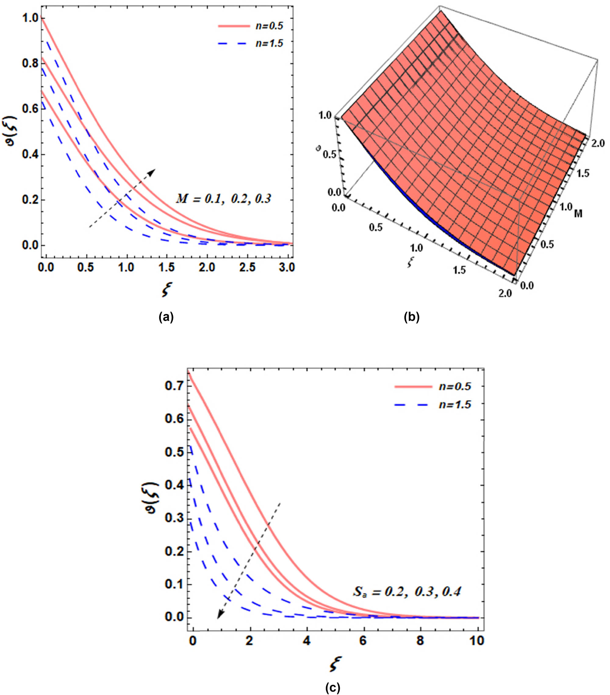
(a) Effect of
Thermal Biot number (
(a) Effect of
Lewis number (Lb): Understanding mass transfer phenomena requires knowledge of how the Lewis number influences concentration profile development in diffusion and heat transfer processes. Figure 6a and b shows the influence of the Lewis number (Lb) on the concentration profile for different values of n (0.5 and 1.5). When the Lewis number is less than 1, mass transfer processes proceed at a slower rate compared to thermal transfer processes. The boundary layer expansion results in an extended area, where concentration changes slowly throughout the distance. The phenomenon leads to a distinct concentration gradient in the boundary area when mass diffusion occurs more quickly than heat diffusion when the Lewis number is less than 1. The diverse concentration profile shapes have substantial effects on systems in which heat and concentration gradients actively affect the final process results. Lewis number serves as a vital parameter that plants and chemical reactions need for designing heat exchangers, as well as chemical reactors and drying systems. Chemical reactor performance optimization depends on Lewis number applications during design for simultaneous control of reaction rates and temperature and concentration gradients.

(a) Effect of
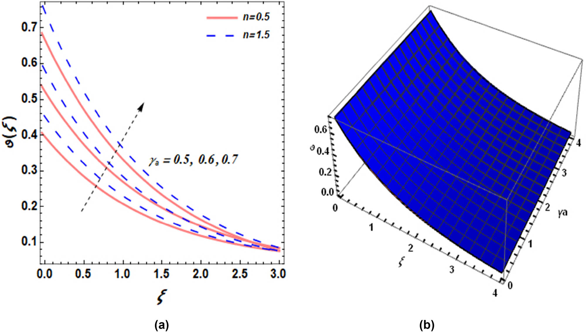
Microorganism’s Biot number: The microorganism’s Biot number represents the relation between the internal body resistance for heat or mass transfer and surface resistance to heat or mass transfer. The Biot number plays a vital role in microorganisms by determining the efficiency of environmental heat and mass transfers between their inner structure and external factors. An increase in the microorganism’s biot number indicates that the internal temperature and substrate concentrations within the microorganism fail to align with the external environment (Figure 6c). This imbalance leads to slower thermal and material diffusion processes, resulting in uneven substrate concentration distribution throughout the microorganism, which ultimately diminishes its functional efficiency. Higher value Biot number values indicate that the microorganisms encounter stronger barriers for heat or mass transport inside their structure. The Biot number is a critical parameter for analyzing the behavior of microorganism systems under various conditions. As the Biot number increases, the internal resistance to heat and mass transfer within the microorganisms becomes more dominant compared to the external resistance. This change alters concentration gradients and significantly impacts biological processes. The Biot number brings practical value to various industries through biotechnology and environmental engineering, and medical applications that require optimized microorganism performance for desired results.
Brinkman number and temperature difference parameter: The Brinkman number analyzes the dominant relationship between fluid resistance controls and the thermal energy spread when fluids move through a system. Figure 7a illustrates the increase in the entropy profile corresponding to an increase in the Brinkman number. Internal fluid friction produces heat through viscous dissipation when shear stress acts on the fluid matter. The fluid attains higher entropy because viscous dissipation surpasses thermal conductivity when the Brinkman number increases. The system generates novel entropy changes when Brinkman number values increase, which affect analytical models that depend on the thermodynamics. Internal energy losses can be controlled through entropy calculations that determine disorder measurement and randomness evaluation during viscous dissipation. Figure 7(b) illustrates how increasing the temperature difference parameter leads to greater entropy generation.

(a) Effect of
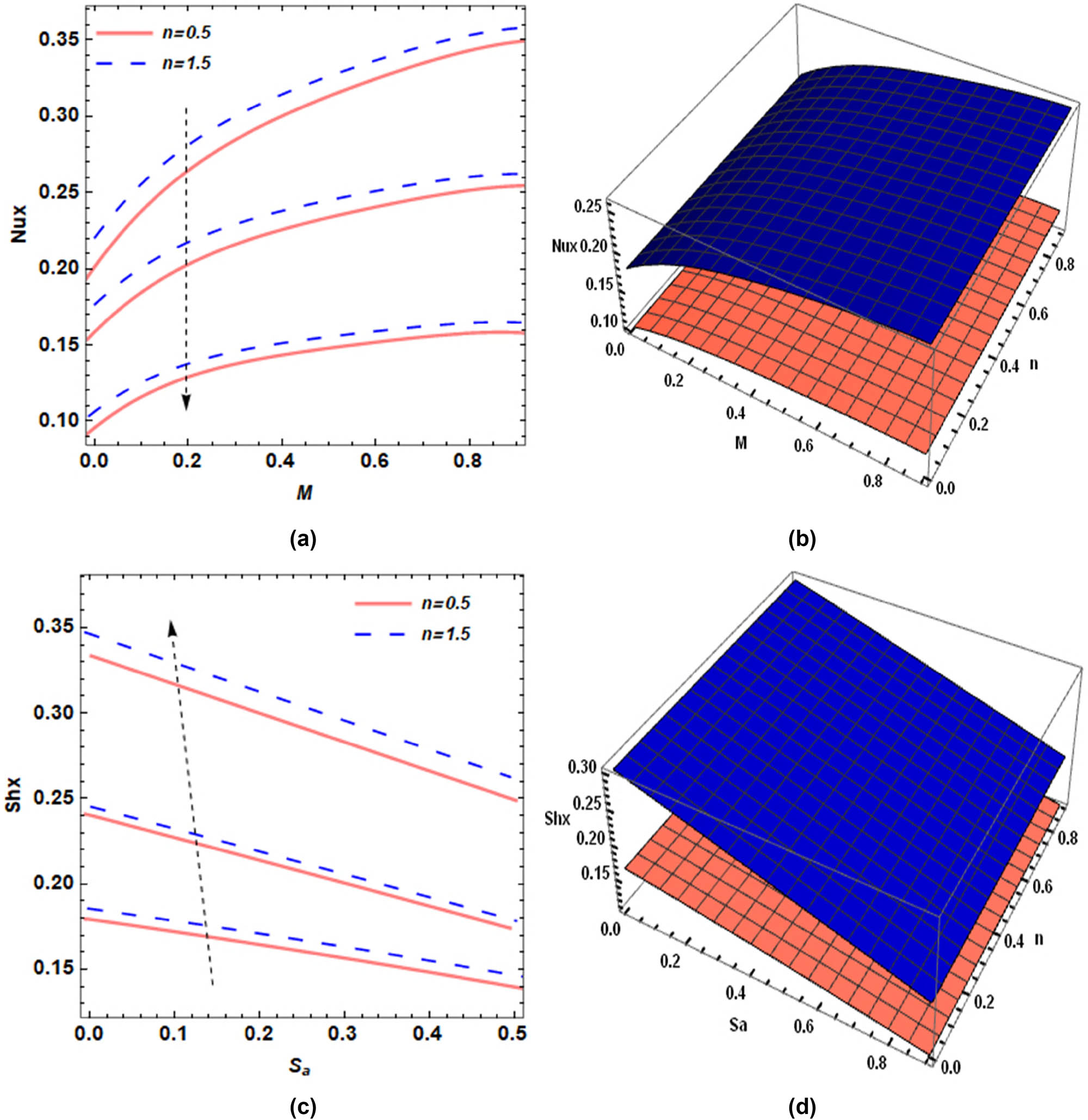
The effect of the magnetic parameter (M) on the heat transport rate is demonstrated in Figure 8a and b, respectively. The figure demonstrates the influence that magnetic fields have on the heat transport rate through fluid flow systems. The figure illustrates that the heat transport rate increases with M, and this increase becomes particularly pronounced at higher values of n. The magnetic field’s interaction with electrically conducting fluids contributes to this observed behavior because of MHD principles. The phenomenon of the Lorentz force occurs when electrically conducting fluids experience resistance under a magnetic field influence. Fluid resistance from this force creates hurdles to flow motion, which reduces convection currents while decreasing system-wide energy transmission. The Nusselt number decreases when thermal diffusion surpasses convection. An elevated magnetic parameter value results in more robust resistive forces that decrease convective heat transfer efficiency. The effect of the thermal stratification parameter on the local Sherwood number is depicted in Figure 8c and d, illustrating the variation in mass transfer behavior under different stratification conditions.
(a) Effect of
7 Conclusions
This study investigates the thermal performance of Sutterby nanofluid flow influenced by bio-convection, electrical conductivity, and Hall current over a bidirectionally stretching surface. To enhance efficiency, the analysis considers entropy generation, chemical reactions, activation energy, viscous dissipation, and magnetic field effects. The governing partial differential equations are reduced to a system of ordinary differential equations and solved numerically using the CCSM. The main findings of this work are summarized as follows:
An increase in the microorganism’s Biot number enhances the heat transfer rate from the fluid to the microorganisms, leading to an elevated concentration profile.
An increased Lewis number signifies a stronger dominance of thermal diffusion over mass diffusion, leading to a decline in the concentration profile.
An increase in thermal stratification leads to a decline in the temperature profile, as temperature gradients become more pronounced.
A higher magnetic parameter enhances temperature due to Joule heating effects, leading to increased thermal energy dissipation in conducting fluids.
An increased thermal Biot number improves heat transfer efficiency between the fluid and its surroundings, leading to an increase in the temperature profile.
A higher thermal diffusivity facilitates more effective heat transfer, resulting in an increased temperature profile.
As the Brinkman number increases, entropy production increases due to stronger viscous dissipation effects.
Acknowledgments
The authors thank the Deanship of Graduate Studies and Scientific Research, Islamic University of Madinah, Madinah, Saudi Arabia, for supporting this research work.
-
Funding information: The authors appreciate the funding received from the Deanship of Graduate Studies and Scientific Research, Islamic University of Madinah, Madinah, Saudi Arabia, for supporting this research work.
-
Author contributions: A.M.O.: conceptualization, methodology, software, formal analysis, validation, and writing – original draft. M.W.: writing–original draft, data curation, investigation, visualization, and validation. U.K.: conceptualization, writing–original draft, writing – review and editing, supervision, and resources. S.M.H.: validation, investigation, writing – review and editing, formal analysis, project administration, funding acquisition, and software.
-
Conflict of interest: The authors state no conflict of interest.
-
Data availability statement: The datasets used and/or analyzed during the current study are available from the corresponding author upon reasonable request.
References
[1] Ramzan M, Chung JD, Ullah N. Radiative magnetohydrodynamic nanofluid flow due to gyrotactic microorganisms with chemical reaction and non-linear thermal radiation. Int J Mech Sci. 2017;130:31–40.10.1016/j.ijmecsci.2017.06.009Search in Google Scholar
[2] Muhammad S, Ali G, Shah Z, Islam S, Hussain SA. The rotating flow of magnetohydrodynamic carbon nanotubes over a stretching sheet with the impact of non-linear thermal radiation and heat generation/absorption. Appl Sci. 2018;8(4):482.10.3390/app8040482Search in Google Scholar
[3] Gul T, Waqas M, Noman W, Zaheer Z, Amiri IS. The carbon-nanotube nanofluid sprayed on an unsteady stretching cylinder together with entropy generation. Adv Mech Eng. 2019;11(12):1687814019894454.10.1177/1687814019894454Search in Google Scholar
[4] Sreedevi P, Reddy PS, Sheremet M. A comparative study of Al2O3 and TiO2 nanofluid flow over a wedge with non-linear thermal radiation. Int J Numer Methods Heat Fluid Flow. 2020;30(3):1291–317.10.1108/HFF-05-2019-0434Search in Google Scholar
[5] Hayat T, Khan AA, Bibi F, Alsaedi A. Entropy minimization for magneto peristaltic transport of Sutterby materials subject to temperature dependent thermal conductivity and non-linear thermal radiation. Int Commun Heat Mass Transf. 2021;122:105009.10.1016/j.icheatmasstransfer.2020.105009Search in Google Scholar
[6] Khan Z, Srivastava HM, Mohammed PO, Jawad M, Jan R, Nonlaopon K. Thermal boundary layer analysis of MHD nanofluids across a thin needle using non-linear thermal radiation. Math Biosci Eng. 2022;19(12):14116–41.10.3934/mbe.2022658Search in Google Scholar PubMed
[7] Iftikhar B, Javed T, Siddiqui MA. Natural convective flow of non-isothermal hybrid nanofluid inside the cavity with the influence of a heated fin and non-linear thermal radiation: Second law analysis. Mater Today Commun. 2023;34:105341.10.1016/j.mtcomm.2023.105341Search in Google Scholar
[8] Gasmi H, Obalalu AM, Khan U, Ishak A, Balogun AO, Alessa N, et al. Irreversibility analysis of the two-phase non-Newtonian nanofluid model induced by converging/diverging channels with heat source/sink and viscous dissipation effects. Alex Eng J. 2025;123:497–510.10.1016/j.aej.2025.03.066Search in Google Scholar
[9] Gasmi H, Obalalu AM, Khan U, Ishak A, Gundogdu H, Abdullah N, et al. Analysis of advanced cooling strategies for rocket engines conveying ternary hybrid nanofluids with second slip conditions and melting heat transfer. Case Stud Therm Eng. 2025;72:106312.10.1016/j.csite.2025.106312Search in Google Scholar
[10] Wang Y, Yu L, Obalalu AM, Khan U, Waqas M, Elrashidi A, et al. Dissipative heat transfer in blood-based ternary hybrid nanofluids through a parallel channel with entropy optimization: the case of biomedical applications. Alex Eng J. 2025;115:252–63.10.1016/j.aej.2024.12.026Search in Google Scholar
[11] Khan U, Obalalu AM, Zaib A, Ishak A, Hussain SM, Madhukesh JK, et al. Irreversibility analysis of cross-flow in Eyring–Powell nanofluid over a permeable deformable sheet with Lorentz forces. ZAMM. 2025;105(2):e202300835.10.1002/zamm.202300835Search in Google Scholar
[12] Olayemi OA, Oladimeji LT, Ibitoye SE, Obalalu AM, Olayemi DO, Khan U, et al. Dynamic features of heat transfer in a square enclosure induced by an adiabatic rotating circular cylinder with double-diffusive buoyancy forces. ZAMM. 2025;105(1):e202400964.10.1002/zamm.202400964Search in Google Scholar
[13] Obalalu AM, Fatunmbi EO, Alam MM, Abbas A, Khan U, Adekoya-Olowofela A, et al. Influence of thermal radiation and electromagnetic characteristics of micropolar ternary hybrid nanofluid flow over a slender surface. J Radiat Res Appl Sci. 2025;18(1):101268.10.1016/j.jrras.2024.101268Search in Google Scholar
[14] Ogunsanwo GO, Alaba OB, Obalalu AM, Isarinade AF, Khan U, Ghodhbani R, et al. Dynamics of second-law analysis and thermal performance in solar-powered tractors using a parabolic trough solar collector filled with tri-hybrid nanofluid. J Therm Anal Calorim. 2025;150:1–16.10.1007/s10973-025-14334-1Search in Google Scholar
[15] Bulman WE. Applications of the Hall effect. Solid State Electron. 1966;9(5):361–72.10.1016/0038-1101(66)90150-XSearch in Google Scholar
[16] Ramsden E. Hall-effect sensors: theory and application. Oxford: Elsevier; 2011.Search in Google Scholar
[17] Chien C. The Hall effect and its applications. Berlin: Springer; 2013.Search in Google Scholar
[18] Khan U, Zaib A, Ishak A, Elattar S, Eldin SM, Raizah Z, et al. Impact of irregular heat sink/source on the wall jet flow and heat transfer in a porous medium induced by a nanofluid with slip and buoyancy effects. Symmetry. 2022;14(10):2212.10.3390/sym14102212Search in Google Scholar
[19] Karsenty A. A comprehensive review of integrated Hall effects in macro-, micro-, nanoscales, and quantum devices. Sensors. 2020;20(15):4163.10.3390/s20154163Search in Google Scholar PubMed PubMed Central
[20] Du ZZ, Lu HZ, Xie XC. Nonlinear Hall effects. Nat Rev Phys. 2021;3(11):744–52.10.1038/s42254-021-00359-6Search in Google Scholar
[21] Hu S, Shao DF, Yang H, Pan C, Fu Z, Tang M, et al. Efficient perpendicular magnetization switching by a magnetic spin Hall effect in a noncollinear antiferromagnet. Nat Commun. 2022;13(1):4447.10.1038/s41467-022-32179-2Search in Google Scholar PubMed PubMed Central
[22] El-Amin MF. Combined effect of viscous dissipation and Joule heating on MHD forced convection over a non-isothermal horizontal cylinder embedded in a fluid saturated porous medium. J Magn Magn Mater. 2003;263(3):337–43.10.1016/S0304-8853(03)00109-4Search in Google Scholar
[23] Chen CH. Combined effects of Joule heating and viscous dissipation on magnetohydrodynamic flow past a permeable, stretching surface with free convection and radiative heat transfer. Commun Nonlinear Sci Numer Simul. 2010;15(6):1803–12.10.1115/1.4000946Search in Google Scholar
[24] Mishra A, Kumar M. Velocity and thermal slip effects on MHD nanofluid flow past a stretching cylinder with viscous dissipation and Joule heating. SN. Appl Sci. 2020;2(8):1350.10.1007/s42452-020-3156-7Search in Google Scholar
[25] Khan MR, Mao S, Deebani W, Elsiddieg AM. Numerical analysis of heat transfer and friction drag relating to the effect of Joule heating, viscous dissipation and heat generation/absorption in aligned MHD slip flow of a nanofluid. Int Commun Heat Mass Transf. 2022;131:105843.10.1016/j.icheatmasstransfer.2021.105843Search in Google Scholar
[26] Jayanthi S, Niranjan H. Effects of Joule heating, viscous dissipation, and activation energy on nanofluid flow induced by MHD on a vertical surface. Symmetry. 2023;15(2):314.10.3390/sym15020314Search in Google Scholar
[27] Mishra S, Swain K, Dalai R. Joule heating and viscous dissipation effects on heat transfer of hybrid nanofluids with thermal slip. Iran J Sci Technol Trans. Mech Eng. 2024;48(2):531–9.10.1007/s40997-023-00681-7Search in Google Scholar
[28] Rilwan US, Oni MO, Jibril HM, Jha BK. Effects of Joule heating and viscous dissipation on electromagneto-hydrodynamic flow in a microchannel with electroosmotic effect: Enhancement of MEMS cooling. Proc Inst Mech Eng N J Nanomater Nanoeng Nanosyst. 2024;23977914231217929.10.1177/23977914231217929Search in Google Scholar
[29] Zhou M, Hu Y, Yan Z, Fu H. Flexible MXene-based Janus film with superior heat dissipation capability for ultra-efficient electromagnetic interference shielding and Joule heating. Carbon. 2024;219:118835.10.1016/j.carbon.2024.118835Search in Google Scholar
[30] Ibabe A, Steffensen GO, Casal I, Gomez M, Kanne T, Nygard J, et al. Heat dissipation mechanisms in hybrid superconductor–semiconductor devices revealed by Joule spectroscopy. Nano Lett. 2024;24(6):1500–7.10.1021/acs.nanolett.4c00574Search in Google Scholar PubMed PubMed Central
[31] Spinelli G, Guarini R, Vertuccio L, Guadagno L, Romano V. Simulation and experimental comparison of Joule-heating effect in carbon-based epoxy resin. Macromol Symp. 2024;413(4):2400034.10.1002/masy.202400034Search in Google Scholar
[32] Mir NA, Farooq M, Rizwan M, Ahmad F, Ahmad S, Ahmad B. Analysis of thermally stratified flow of Sutterby nanofluid with zero mass flux condition. J Mater Res Technol. 2020;9(2):1631–9.10.1016/j.jmrt.2019.11.088Search in Google Scholar
[33] Nawaz M. Role of hybrid nanoparticles in thermal performance of Sutterby fluid, the ethylene glycol. Phys A Stat Mech Appl. 2020;537:122447.10.1016/j.physa.2019.122447Search in Google Scholar
[34] Akram J, Akbar NS, Tripathi D. Blood-based graphene oxide nanofluid flow through capillary in the presence of electromagnetic fields: A Sutterby fluid model. Microvasc Res. 2020;132:104062.10.1016/j.mvr.2020.104062Search in Google Scholar PubMed
[35] Khan WA, Anjum N, Waqas M, Abbas SZ, Irfan M, Muhammad T. Impact of stratification phenomena on a nonlinear radiative flow of Sutterby nanofluid. J Mater Res Technol. 2021;15:306–14.10.1016/j.jmrt.2021.08.011Search in Google Scholar
[36] Khan MP, Chang CY, Raja MAZ, Shoaib M. Novel machine learning investigation for Buongiorno fluidic model with Sutterby nanomaterial. Tribol Int. 2024;199:110009.10.1016/j.triboint.2024.110009Search in Google Scholar
[37] Pasha AA, Kausar MS, Nasir M, Waqas M, Zamri N, Juhany KA, et al. Analysis of electro-magnetized dual diffusive Sutterby nanofluid in a reactive-stratified squeezed regime with thermal radiation. Int Commun Heat Mass Transf. 2024;158:107900.10.1016/j.icheatmasstransfer.2024.107900Search in Google Scholar
[38] Irfan M, Muhammad T. Numerical simulation of bio-convection radiative heat transport flow of MHD Carreau nanofluid. Z Angew Math Mech. 2024;104(11):e202300813.10.1002/zamm.202300813Search in Google Scholar
[39] Irfan M, Anwar MS, Alghamdi M, Khan M, Muhammad T. Modeling heat-mass transport for MHD bio-convection Carreau nanofluid with Joule heating containing both gyrotactic microbes and nanoparticles diffusion. Z Angew Math Mech. 2024;104(10):e202400234.10.1002/zamm.202400234Search in Google Scholar
[40] Ali U, Irfan M. Thermal performance of Joule heating in radiative Eyring-Powell nanofluid with Arrhenius activation energy and gyrotactic motile microorganisms. Heliyon. 2024;10(3):e2524.10.1016/j.heliyon.2024.e25070Search in Google Scholar PubMed PubMed Central
[41] Ali U, Irfan M. Study of gyrotactic motile microorganisms in Powell–Eyring nanofluid with non-Fourier and non-Fick’s theories. J Therm Anal Calorim. 2025;150(4):2375–91.10.1007/s10973-024-13402-2Search in Google Scholar
[42] Irfan M, Muhammad T, Rashid M, Anwar MS, Abas SS, Narayana PS. Numerical study of nonlinear thermal radiation and Joule heating on MHD bioconvection Carreau nanofluid with gyrotactic microorganisms. J Radiat Res Appl Sci. 2025;18(1):101254.10.1016/j.jrras.2024.101254Search in Google Scholar
[43] Javed M, Tariq J, Irfan M, Mehmood R. Melting rheology in chemically reactive flow of dual stratified Eyring–Powell nanoliquid due to stretching sheet of variable thickness. Results Eng. 2025;26:104843.10.1016/j.rineng.2025.104843Search in Google Scholar
[44] Irfan M, Sunthrayuth P, Ali Pasha A, Anwar MS, Azeem Khan W. Phenomena of thermo-solutal time’s relaxation in mixed convection Carreau fluid with heat sink/source. Waves Random Complex Media. 2025;35(2):4008–20.10.1080/17455030.2022.2056658Search in Google Scholar
[45] Mingliang Z, Kallel M, Ijaz N, Zeeshan A. Nonlinear mixed convection dynamics of microorganisms in tetra hydro-metamaterial systems: Machine learning models for thermal-biological interface control. Int Commun Heat Mass Transf. 2025;167:109366.10.1016/j.icheatmasstransfer.2025.109366Search in Google Scholar
[46] Amjad AB, Sellami R, Khan MI, Zeeshan A, Ijaz N, Hazim A. Gyrotactic microorganisms in the pharmacokinetics of electrically conducted nanofluid over a stretching sheet: complex algorithmic models. Multiscale Multidiscip Model Exp Des. 2025;8(6):1–16.10.1007/s41939-025-00869-1Search in Google Scholar
[47] Bibi M, Zeeshan A, Malik MY. Numerical analysis of unsteady flow of three-dimensional Williamson fluid-particle suspension with MHD and nonlinear thermal radiations. Eur Phys J Plus. 2020;135(10):850.10.1140/epjp/s13360-020-00857-zSearch in Google Scholar
[48] Majeed A, Golsanami N, Gong B, Ahmad QA, Rifaqat S, Zeeshan A, et al. Analysis of thermal radiation in magnetohydrodynamic motile gyrotactic microorganisms flow comprising tiny nanoparticle towards a nonlinear surface with velocity slip. Alex Eng J. 2023;66:543–53.10.1016/j.aej.2022.11.012Search in Google Scholar
[49] Zeeshan A, Ellahi R, Rafique MA, Sait SM, Shehzad N. Parametric optimization of entropy generation in hybrid nanofluid in contracting/expanding channel by means of analysis of variance and response surface methodology. Inventions. 2024;9(5):92.Search in Google Scholar
[50] Mehboob J, Ellahi R, Sait SM, Akbar NS. Optimizing bioconvective heat transfer with MHD Eyring–Powell nanofluids containing motile microorganisms with viscosity variability and porous media in ciliated microchannels. Int J Numer Methods Heat Fluid Flow. 2025;35(2):825–46.10.1108/HFF-11-2024-0838Search in Google Scholar
[51] Sait SM, Riaz A, Shaheen S, Ellahi R, Akram S. Thermally induced cilia flow of Prandtl nanofluid under the influence of electroosmotic effects with boundary slip. J Taibah Univ Sci. 2025;19(1):2484877.10.1080/16583655.2025.2484877Search in Google Scholar
[52] Zeeshan A, Khalid N, Ellahi R, Khan MI, Alamri SZ. Analysis of nonlinear complex heat transfer MHD flow of Jeffrey nanofluid over an exponentially stretching sheet via three phase artificial intelligence and machine learning techniques. Chaos Solitons Fractals. 2024;189:115600.10.1016/j.chaos.2024.115600Search in Google Scholar
[53] Ellahi R. The effects of MHD and temperature dependent viscosity on the flow of non-Newtonian nanofluid in a pipe: analytical solutions. Appl Math Model. 2013;37(3):1451–67.10.1016/j.apm.2012.04.004Search in Google Scholar
[54] Zeeshan A, Ellahi R, Rafique MA, Sait SM, Shehzad N. Parametric optimization of entropy generation in hybrid nanofluid in contracting/expanding channel by means of analysis of variance and response surface methodology. Inventions. 2024;9(5):92.10.3390/inventions9050092Search in Google Scholar
[55] Jameel M, Shah Z, Rooman M, Alshehri MH, Vrinceanu N, Antonescu E. Entropy driven optimization of non-linear radiative chemically reactive Sutterby nanofluid flow in presence of gyrotactic micro-organism with Hall effect and activation energy. Sci Rep. 2024;14(1):1–36.Search in Google Scholar
[56] Shah Z, Islam S, Gul T, Bonyah E, Khan MA. The electrical MHD and hall current impact on micropolar nanofluid flow between rotating parallel plates. Results Phys. 2018;9:1201–14.10.1016/j.rinp.2018.01.064Search in Google Scholar
[57] Obalalu AM, Salawu SO, Olayemi OA, Ajala OA, Issa K. Analysis of hydromagnetic Williamson fluid flow over an inclined stretching sheet with Hall current using Galerkin Weighted Residual Method. Comput Math Appl. 2023;146:22–32.10.1016/j.camwa.2023.06.021Search in Google Scholar
[58] Jameel M, Shah Z, Rooman M, Alshehri MH, Vrinceanu N, Antonescu E. Entropy driven optimization of non-linear radiative chemically reactive Sutterby nanofluid flow in presence of gyrotactic microorganism with Hall effect and activation energy. Sci Rep. 2024;14(1):1–36.10.1038/s41598-024-81932-8Search in Google Scholar PubMed PubMed Central
© 2025 the author(s), published by De Gruyter
This work is licensed under the Creative Commons Attribution 4.0 International License.
Articles in the same Issue
- Research Articles
- Modification of polymers to synthesize thermo-salt-resistant stabilizers of drilling fluids
- Study of the electronic stopping power of proton in different materials according to the Bohr and Bethe theories
- AI-driven UAV system for autonomous vehicle tracking and license plate recognition
- Enhancement of the output power of a small horizontal axis wind turbine based on the optimization approach
- Design of a vertically stacked double Luneburg lens-based beam-scanning antenna at 60 GHz
- Synergistic effect of nano-silica, steel slag, and waste glass on the microstructure, electrical resistivity, and strength of ultra-high-performance concrete
- Expert evaluation of attachments (caps) for orthopaedic equipment dedicated to pedestrian road users
- Performance and rheological characteristics of hot mix asphalt modified with melamine nanopowder polymer
- Second-order design of GNSS networks with different constraints using particle swarm optimization and genetic algorithms
- Impact of including a slab effect into a 2D RC frame on the seismic fragility assessment: A comparative study
- Analytical and numerical analysis of heat transfer from radial extended surface
- Comprehensive investigation of corrosion resistance of magnesium–titanium, aluminum, and aluminum–vanadium alloys in dilute electrolytes under zero-applied potential conditions
- Performance analysis of a novel design of an engine piston for a single cylinder
- Modeling performance of different sustainable self-compacting concrete pavement types utilizing various sample geometries
- The behavior of minors and road safety – case study of Poland
- The role of universities in efforts to increase the added value of recycled bucket tooth products through product design methods
- Adopting activated carbons on the PET depolymerization for purifying r-TPA
- Urban transportation challenges: Analysis and the mitigation strategies for road accidents, noise pollution and environmental impacts
- Enhancing the wear resistance and coefficient of friction of composite marine journal bearings utilizing nano-WC particles
- Sustainable bio-nanocomposite from lignocellulose nanofibers and HDPE for knee biomechanics: A tribological and mechanical properties study
- Effects of staggered transverse zigzag baffles and Al2O3–Cu hybrid nanofluid flow in a channel on thermofluid flow characteristics
- Mathematical modelling of Darcy–Forchheimer MHD Williamson nanofluid flow above a stretching/shrinking surface with slip conditions
- Energy efficiency and length modification of stilling basins with variable Baffle and chute block designs: A case study of the Fewa hydroelectric project
- Renewable-integrated power conversion architecture for urban heavy rail systems using bidirectional VSC and MPPT-controlled PV arrays as an auxiliary power source
- Exploitation of landfill gas vs refuse-derived fuel with landfill gas for electrical power generation in Basrah City/South of Iraq
- Two-phase numerical simulations of motile microorganisms in a 3D non-Newtonian nanofluid flow induced by chemical processes
- Sustainable cocoon waste epoxy composite solutions: Novel approach based on the deformation model using finite element analysis to determine Poisson’s ratio
- Impact and abrasion behavior of roller compacted concrete reinforced with different types of fibers
- Architectural design and its impact on daylighting in Gayo highland traditional mosques
- Structural and functional enhancement of Ni–Ti–Cu shape memory alloys via combined powder metallurgy techniques
- Design of an operational matrix method based on Haar wavelets and evolutionary algorithm for time-fractional advection–diffusion equations
- Design and optimization of a modified straight-tapered Vivaldi antenna using ANN for GPR system
- Analysis of operations of the antiresonance vibration mill of a circular trajectory of chamber vibrations
- Functions of changes in the mechanical properties of reinforcing steel under corrosive conditions
- Enhanced PAPR reduction in NOMA systems using modified SLM and PTS techniques for power-efficient 5G and beyond networks
- Hybrid mechanics-informed machine learning models for predicting mechanical failure in graphene sponge: a low-data strategy for mechanical engineering applications
- Design of shafts of a two-piece chain conveyor as a part of a modification of a mobile working machine
- Review Articles
- A modified adhesion evaluation method between asphalt and aggregate based on a pull off test and image processing
- Architectural practice process and artificial intelligence – an evolving practice
- 10.1515/eng-2025-0148
- Special Issue: 51st KKBN - Part II
- The influence of storing mineral wool on its thermal conductivity in an open space
- Use of nondestructive test methods to determine the thickness and compressive strength of unilaterally accessible concrete components of building
- Use of modeling, BIM technology, and virtual reality in nondestructive testing and inventory, using the example of the Trzonolinowiec
- Tunable terahertz metasurface based on a modified Jerusalem cross for thin dielectric film evaluation
- Integration of SEM and acoustic emission methods in non-destructive evaluation of fiber–cement boards exposed to high temperatures
- Non-destructive method of characterizing nitrided layers in the 42CrMo4 steel using the amplitude-frequency technique of eddy currents
- Evaluation of braze welded joints using the ultrasonic method
- Analysis of the potential use of the passive magnetic method for detecting defects in welded joints made of X2CrNiMo17-12-2 steel
- Analysis of the possibility of applying a residual magnetic field for lack of fusion detection in welded joints of S235JR steel
- Eddy current methodology in the non-direct measurement of martensite during plastic deformation of SS316L
- Methodology for diagnosing hydraulic oil in production machines with the additional use of microfiltration
- Special Issue: IETAS 2024 - Part II
- Enhancing communication with elderly and stroke patients based on sign-gesture translation via audio-visual avatars
- Optimizing wireless charging for electric vehicles via a novel coil design and artificial intelligence techniques
- Evaluation of moisture damage for warm mix asphalt (WMA) containing reclaimed asphalt pavement (RAP)
- Comparative CFD case study on forced convection: Analysis of constant vs variable air properties in channel flow
- Evaluating sustainable indicators for urban street network: Al-Najaf network as a case study
- Node failure in self-organized sensor networks
- Comprehensive assessment of side friction impacts on urban traffic flow: A case study of Hilla City, Iraq
- Design a system to transfer alternating electric current using six channels of laser as an embedding and transmitting source
- Security and surveillance application in 3D modeling of a smart city: Kirkuk city as a case study
- Modified biochar derived from sewage sludge for purification of lead-contaminated water
- The future of space colonisation: Architectural considerations
- Design of a Tri-band Reconfigurable Antenna Using Metamaterials for IoT Applications
- Special Issue: AESMT-7 - Part II
- Experimental study on behavior of hybrid columns by using SIFCON under eccentric load
- Special Issue: ICESTA-2024 and ICCEEAS-2024
- A selective recovery of zinc and manganese from the spent primary battery black mass as zinc hydroxide and manganese carbonate
- Special Issue: REMO 2025 and BUDIN 2025
- Predictive modeling coupled with wireless sensor networks for sustainable marine ecosystem management using real-time remote monitoring of water quality
- Management strategies for refurbishment projects: A case study of an industrial heritage building
- Structural evaluation of historical masonry walls utilizing non-destructive techniques – Comprehensive analysis