
New approach to analysis of railway track dynamics – Rail head vibrations
-
Włodzimierz Czyczuła
 und
Małgorzata Urbanek
und
Małgorzata Urbanek

Abstract
The article presents an original approach to the analysis of railway track dynamics. The “beam-inside-beam” concept is introduced as a dynamic generalisation of the static head-on-web effect, based on the two-layer model of rail. Rail head is a distinguished element of the rail. The system of distributed moving loads excites rail head as a beam supported by the rail web being considered as a viscoelastic layer. Rail head vibration is a kinematic excitation of the whole rail profile, including the rail head. The whole rail is also considered as a beam on viscoelastic foundation with parameters used in typical analyses of railway track dynamics. Vibrations of the whole rail obtained from the analysis of the two-layer “beam-inside-beam” model are compared with vibrations of typical one-layer track model. It is known that the static head-on-web effect is very limited. The range of significant rail head displacements covers nearly 0.6 m of area centred around the wheel position. This observation is also valid in the case of moving constant load. In other words, the dynamic effect of rail head vibrations in the case without imperfections type of track-vehicle is practically the same as in the static head-on-web case. Nevertheless, the analysis of track imperfections impact with various factors influencing the system behaviour, like the axles load and configuration, the track elastic parameters, the length of imperfection, or the train speed, show that the head-on-web effect is significant and should be analysed in more detail. For this purpose, a new model “beam-inside-beam” is proposed. The Fourier series are used to solve the two considered models. The load and unknown functions in the models’ solutions are expanded in the arbitrarily assumed interval which practically covers non-zero track response for the analysed system of parameters (group of wheels). This solving method for equation of motion was experimentally validated in the paper by Czyczula et al. (2017). Validation of the “beam-inside-beam” model is considered as future work and the current article should be recognised as a preliminary study of the analysed effects under assumption of being purely theoretical investigation so far, although forming hierarchically organised building of more complex rail models is possible to partially verify in further steps of modelling process.
1 Introduction
The problem of dynamic response of the track under a moving load is the subject of many theoretical and experimental studies.
Under some assumptions, the beam on elastic foundation can be considered as a typical track model. It is worth to mention that the first study of beams on Winkler foundation subjected to a concentrated force moving with constant speed was initiated by Timoshenko [1]. The first solution to a simple stationary case of the Bernoulli–Euler beam on an elastic foundation was properly obtained by Ludwig [2]. The case of moving and oscillating force was formulated and partly solved by Mathews [3]. The case of varying moving force was studied by Fryba [4] and Bogacz and Krzyżyński [5]. The model of load moving along a sectional structure (varying along the space variable) was analysed by Bogacz [6].
Many papers are devoted to study the various effects of generalised models:
Analysis of beam vibration on elastic half-space [10],
In all the above described generalisations of classical approach, the track response model is composed of rail (as the beam) and viscoelastic or elastic foundation. The sleepers and the ballast are modelled as additional layers.
The rail head effect in a static load case was studied analytically by Orringer et al. [20]. In this article, the effects of rail head vibrations on track response are studied in a steady state case. In the model, both the rail head and the whole rail profile are described as the Bernoulli–Euler beams. The moving load is modelled by a set of distributed forces moving with constant velocity.
2 Rail head as beam on elastic web – static analysis using numerical approach
In the paper by Orringer et al. [20], the rail head is modelled as the Bernoulli–Euler beam with the moment of inertia determined numerically (for US rail only). The stiffness of the web, treated as the head foundation, is described by the formula:
where t – rail web thickness; h – rail web height, and E – Young’s modulus of rail steel.
As rail web thickness is changing and its height is difficult to determine, the numerical analysis is carried out to determine both the rail head foundation and the rail head geometrical parameters. Figure 1 presents cross section of the most popular rail i.e. the 60E1 type. Rail head is selected arbitrarily and the following parameters are used:
moment of inertia in vertical plane: I h = 43.84 × 10⁻⁸ m4;
cross section area: A h = 2,990 × 10−6 m2;
unit mass: m h = 23.3 kg/m.
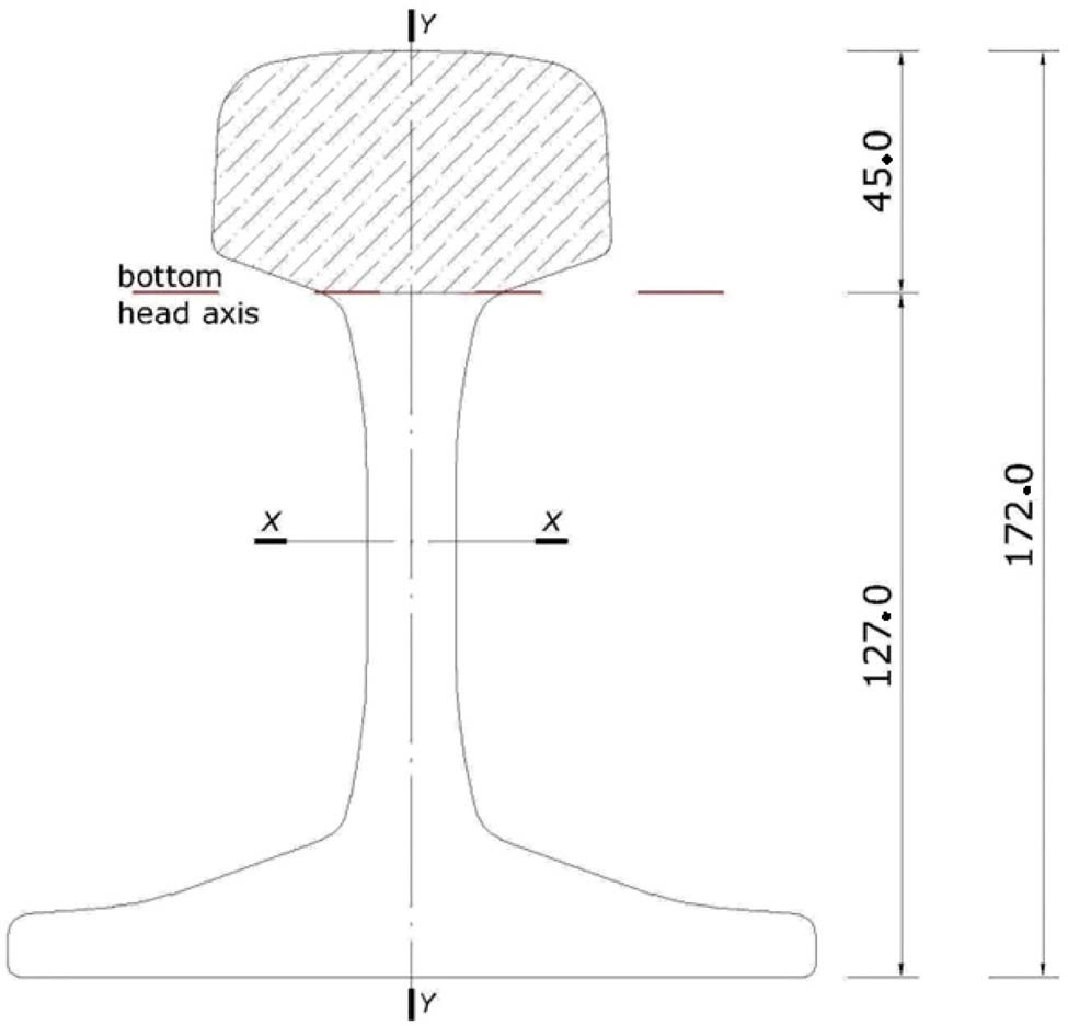
Rail cross section with the rail head separation.
To determine the stiffness of rail head foundation, a 3D numerical model is analysed. A 1 m long 60E1 rail considered as an elastic body is fixed at the bottom, and loaded along the top of the rail by vertical distributed forces with density q = 78.328 kN/m. The rail head foundation stiffness can be calculated with the following simple formula:
where y av is the average vertical displacement of the rail head neutral axis. The rail head foundation stiffness obtained by numerical experiment, according to formula (2), is equal to 0.19 E which is very close to the value 0.2 E obtained by Orringer with the use of equation (1).
3 Steady state response in vertical direction using the two-layer “beam-inside-beam” model
The problem of rail head vibration as “beam-inside-beam” model was mentioned in the paper by Czyczula et al. [21] presenting non-linear formulation of the problem; however, without finalized solution. In this article, a two-layer track model is considered, in which a rail head is distinguished, but not separated from the whole rail profile. The rail head is described as a layer, the vibrations of which are a kinematic excitation of rail longitudinal axis. It is assumed that both the rail head and the whole rail are the Bernoulli–Euler beams with the following parameters:
E = E h = E r – Young’s modulus of rail steel (N/m2);
I h and I r – moments of inertia of rail head and the whole rail profile, respectively (m4);
m h and m r – unit mass of rail head and the whole rail profile, respectively (kg/m);
N h and N r – axial forces in rail head and the whole rail profile, respectively (should be considered as constant along the track) (N). Assuming that (k h [N/m2], c h [Ns/m2]) is viscoelastic constraint describing rail head foundation (rail web) properties, and (k r [N/m2], c r [Ns/m2]) describing viscoelastic properties of rail foundation, the “beam-inside-beam” system can be described by the following system of equations:
where q(x, t) is a unit load acting on a rail head (N/m).
After introducing the moving coordinate system (η = y, χ = y h , ξ = x − vt), equation (3) can be written as follows:
For a set of moving distributed forces changing harmonically in time with circular frequency ω, the load q(ξ, t) can be expressed as:
where q c and q s are cosine and sine parts of the load, respectively.
The steady state solution of (4) can also be described as cosine and sine parts of the rail head and the whole rail profile displacements:
By differentiating equation (6) and substituting together with equation (5), equation (4) becomes a set of ordinary equations associated with the cosine (cos ωt) and the sine (sin ωt) parts:
where L 1,…,L 4 are linear operators of functions Y hc, Y hs, Y rc, Y rs, and their derivatives, while P denotes a set of model parameters. E.g. operator L 1 has the following form:
In order to solve the considered system, a method similar to that presented in the paper by Czyczula et al. [15] can be applied. The distributed loads q c(ξ) and q s(ξ) and the unknown functions Y hc , Y hs, Y rc and Y rs are expanded by the Fourier series in the assumed interval [0, λ], which should cover significantly different from zero response of the track for the analysed group of wheels:
Differentiating functions (9) and substituting the obtained expressions to the set of equation (7) lead to the solution of the system of algebraic equations with unknown coefficients A i , B i , C i , D i, E i , F i , G i , and H i , which can be found by comparison of quantities with the sine and cosine ith series:
In the system (10), the following new parameters are introduced:
The constants Y h01, Y h02, Y r01, and Y r02 (equation [9]) are calculated from the set of equations:
Vibrations of the whole rail profile obtained from the analysis of the two-layer model described above can be compared to the vibrations of rail modelled by one-beam equation (cf. e.g. ref. [15]):
where all parameters are similar to those in equation (3).
4 Numerical examples
The following track and load parameters are used in computational examples:
Rail type of 60E1: Young’s modulus E = 2.1 × 10⁸ kN/m2; moment of inertia in vertical plane I r = 3,055 × 10−8 m4; unit mass m r = 60 kg/m; and longitudinal force in rail N r ≡ 0;
Rail head (60E1 rail): moment of inertia in vertical plane I h = 43.84 × 10⁻⁸ m4; unit mass m h = 23.3 kg/m (cf. Section 2), and longitudinal force in rail head N h ≡ 0;
Rail head foundation: stiffness k h = 0.19 E × 1010 kN/m2 and damping coefficient c h = 0; 20 Ns/m2;
Rail foundation: k r = 91.2 × 10⁶ N/m2 (reference value), also 0.3 and 0.1 of the reference value and c r = 3,950 Ns/m2;
Track irregularities: cosine type – the depth of 10 μm at the length of 0.3 and 0.6 m;
Rail head/wheel contact stiffness: k c = 106 kN/m (cf. ref. [15]);
Load configuration: two wheels of Thalys train with a static load P st = 80,000 N at the distance of 3 m one from another (cf. ref. [16]); four wheels of EMU-250 (Pendolino) train with average static load P st = 78,329 N with distances between them: 2.7, 7.2, and 9.9 m (cf. ref. [22]), four wheels of coal wagons Falns 441 VA with static load P st = 112,500 N; and distances: 1.8, 5.04 and 6.84 m;
Train speed: up to 300 km/h;
Distributed forces approximation: Gauss function (cf. ref. [15]); number of Fourier series coefficients: 2,000–3,000.
It is assumed that the “rail head – wheel” contact is continuous and vibration occurs with a change in the length of contact spring.
Figure 2 shows the difference between a rail head and a whole rail vertical displacements in the case of the Pendolino EMU-250 train in the region of the first axle and with the train speed of 300 km/h. Only forces constant in time are taken into account (corresponding to a track without imperfections). It can be seen that the effect of the head-on-web displacement is relatively small (0.018 mm) and it possesses a local nature. It can be said that displacements of the rail head and the whole rail are practically the same at a distance of more than approximately 0.3 m from the wheel. This conclusion, however, is valid for moving forces constant in time only.
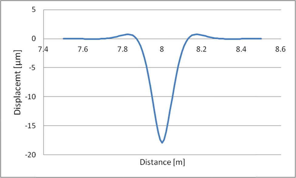
Difference between rail head and whole rail vertical displacements.
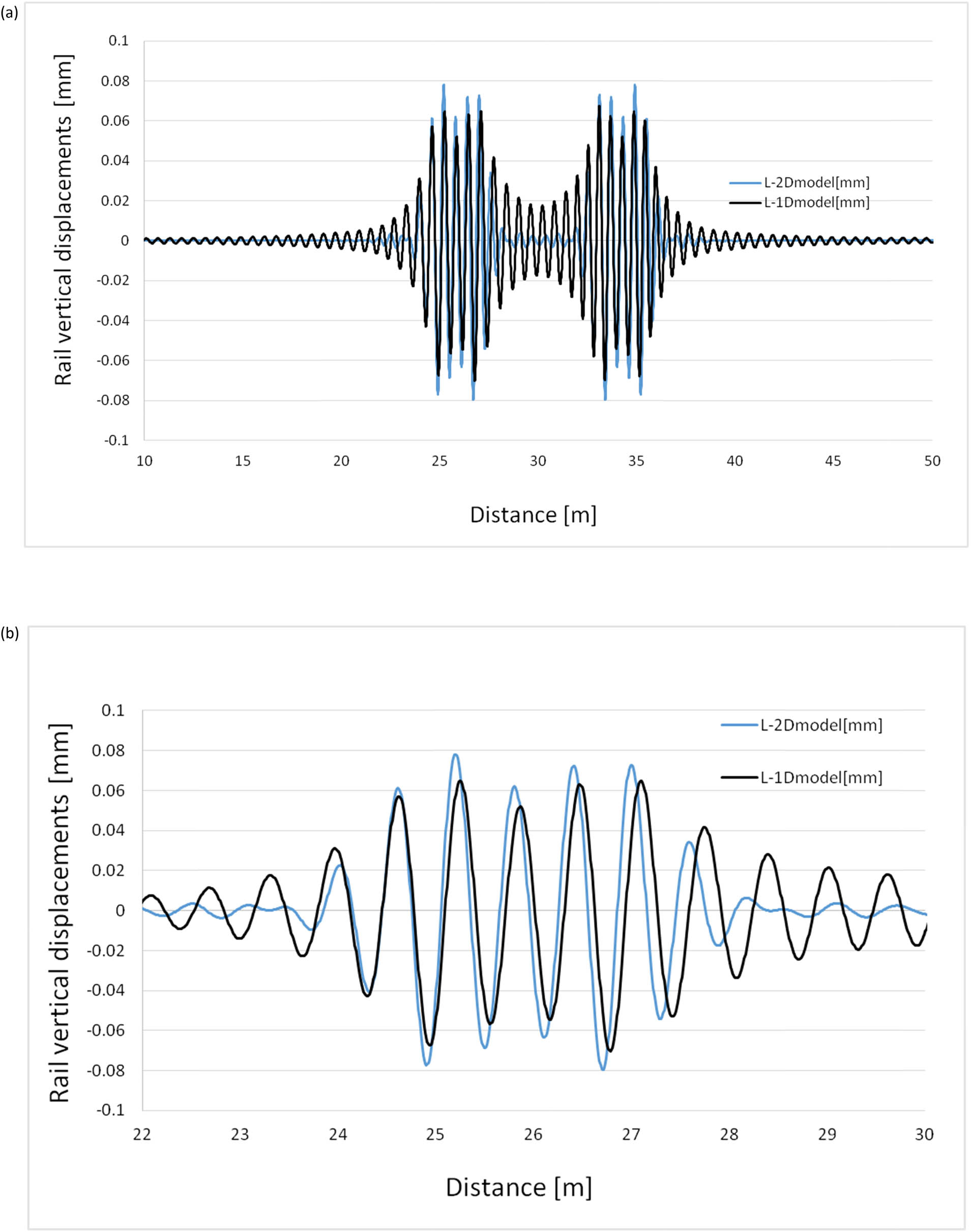
Both Figure 3a and b present rail displacements obtained in the case of the two-layer “beam-inside-beam” model and the one-layer model, with the second one (Figure 3b) as a “zoomed” fragment shown for better recognition of the pattern details. The calculations are carried out for the Pendolino train moving with the speed of 300 km/h along a track with a 10 μm imperfection with the cosine wave with a length of 0.6 m and the track stiffness k r = 91.1 kN/m2. In this case, the difference reaches 0.05 mm and it is spread over 5 m in length. Therefore, the effect of head-on-web should not be considered as local.
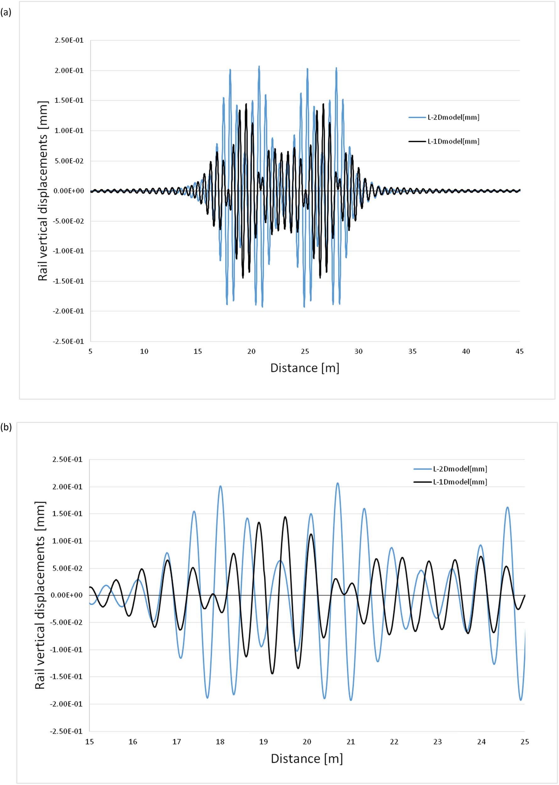
(a) The whole rail displacements for a two-layer (L-2D model) and a one-layer (L-1D model) models (Pendolino train, v = 300 km/h, k r = 91.1 MPa, imperfection s = 10 μm, and L n = 0.6 m) and (b) “Zoomed” graph of a part of (a) solution.
One should mention that an introduction of imperfection in both the considered models leads to the necessity of the analysed distance enlargement due to the increasing range of the response significantly different from zero. Therefore, the interval (0, λ) must be modified according to the particular cases.
Similarly prepared examples are shown in Figures 4 and 5, with second graphs presenting zoomed fragments of the response history in time.
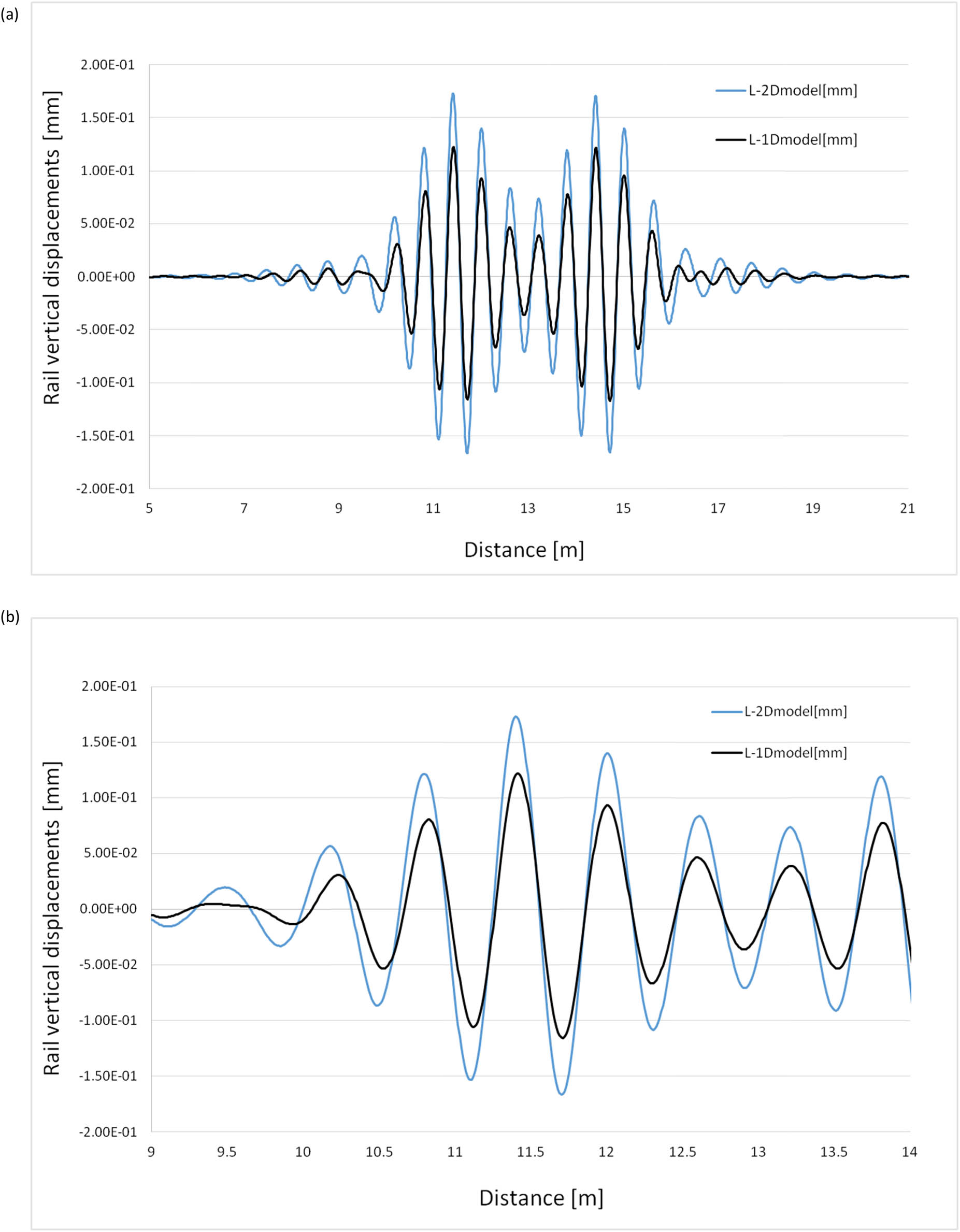
(a) The whole rail displacements for a two-layer (L-2D model) and a one-layer (L-1D model) models (Thalys train, v = 200 km/h, k r = 91.1 MPa, imperfection s = 10 μm, and L n = 0.6 m) and (b) “Zoomed” graph of a part of (a) solution.
(a) Whole rail displacements for a two-layer (L-2D model) and a one-layer (L-1D model) models (coal wagon, v = 100 km/h, k r = 91.1 MPa, imperfection s = 10 μm, and L n = 0.6 m) and (b) “Zoomed” graph of a part of (a) solution.
Both Figure 4a and b present the difference between the two-layer and one-layer rail responses for the Thalys train moving with the speed of 200 km/h on a track with imperfections of 10 μm represented by the cosine wave with a length of 0.3 m and the track stiffness k r = 91.1 kN/m2. In this case, there is also a significant difference between the maximum displacements obtained using both models.
Another example, for a coal wagons, is shown in Figure 5a and b confirming the previously described observations. Here, additionally, a phase shift can be observed which makes the necessity of the head-on-web problem analysis even stronger. However, physical reasons of this phenomena for the considered system of parameters remain an open problem.
Figure 6 shows the maximum difference of displacements between the two-layer and the one-layer cases obtained for the three considered vehicles but for the same set of track parameters and speed v = 100 km/h. This is an example justifying the necessity of more detailed analysis of the analysed phenomenon, taking into account various scenarios of track loads and other track parameters. Results of such a preliminary analysis are gathered in Tables 1–3 showing that the difference in question significantly depends on the selected parameters, i.e. the train speed, the type of train (axle configuration and load characteristics), the track stiffness, and the length of track imperfection.
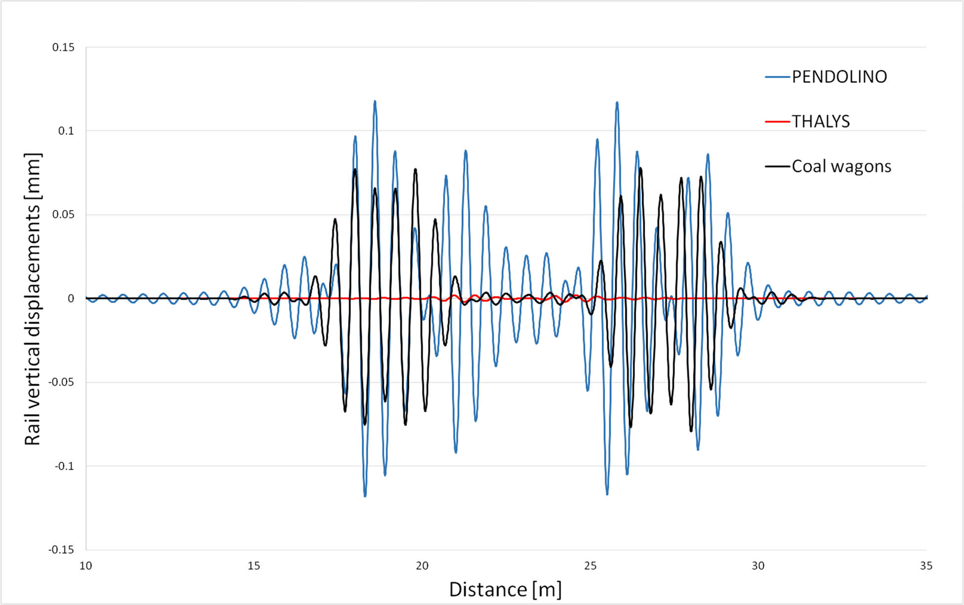
Maximum difference of a two-layer (2-L) and a one-layer (1-L) model displacements (v = 100 km/h, k r = 91.1 MPa, imperfection s = 10 μm, and L n = 0.6 m).
The amplitude differences for the two considered models (Pendolino)
| Pendolino | ||||||
|---|---|---|---|---|---|---|
| Track stiffness | ||||||
| k r = 91.2 × 10⁶ (N/m2) | k r = 0.3 × 91.2 × 106 (N/m2) | k r = 0.1 × 91.2 × 106 (N/m2) | ||||
| Length of cosine wave | ||||||
| L n = 0.3 (m) | L n = 0.6 (m) | L n = 0.3 (m) | L n = 0.6 (m) | L n = 0.3 (m) | L n = 0.6 (m) | |
| v = 100 (km/h) | 0.164 | 0.002 | 2.209 | 0.019 | 0.215 | 0.745 |
| v = 200 (km/h) | 0.601 | 0.009 | 0.195 | 1.729 | 0.31 | 0.568 |
| v = 300 (km/h) | 0.295 | 0.054 | 0.117 | 0.312 | 0.256 | 0.384 |
The amplitude differences for the two considered models (Thalys)
| Thalys | ||||||
|---|---|---|---|---|---|---|
| Track stiffness | ||||||
| k r = 91.2 × 10⁶ (N/m2) | k r = 0.3 × 91.2 × 106 (N/m2) | k r = 0.1 × 91.2 × 106 (N/m2) | ||||
| Length of cosine wave | ||||||
| L n = 0.3 (m) | L n = 0.6 (m) | L n = 0.3 (m) | L n = 0.6 (m) | L n = 0.3 (m) | L n = 0.6 (m) | |
| v = 100 (km/h) | 0.008 | 0.118 | 2.384 | 0.365 | 0.252 | 1.366 |
| v = 200 (km/h) | 0.743 | 0.145 | 0.260 | 1.747 | 0.431 | 1.119 |
| v = 300 (km/h) | 0.304 | 0.253 | 0.113 | 1.031 | 0.265 | 1.580 |
The amplitude differences for the two considered models (coal wagons)
| Coal wagons | ||||||
|---|---|---|---|---|---|---|
| Track stiffness | ||||||
| k r = 91.2 × 10⁶ (N/m2) | k r = 0.3 × 91.2 × 106 (N/m2) | k r = 0.1 × 91.2 × 106 (N/m2) | ||||
| Length of cosine wave | ||||||
| L n = 0.3 (m) | L n = 0.6 (m) | L n = 0.3 (m) | L n = 0.6 (m) | L n = 0.3 (m) | L n = 0.6 (m) | |
| v = 100 (km/h) | 0.135 | 0.062 | 2.655 | 0.216 | 0.899 | 1.397 |
| v = 50 (km/h) | 0.110 | 0.059 | 0.372 | 0.180 | 2.196 | 0.544 |
| v = 20 (km/h) | 0.105 | 0.059 | 0.307 | 0.172 | 0.873 | 0.468 |
One can observe that the length of imperfections significantly influences the investigated characteristics when analysing the two discussed models. One should also underline that the dynamic “head-on-web” effect becomes stronger with increasing train speed and changes with rail foundation stiffness variation.
5 Conclusion
The rail head vibrations effect is described and studied as a new approach to the analysis of the track response under load in vertical direction moving along the track. The analysis is carried out for various train axle configurations, train speeds, lengths of track imperfections, and track foundation stiffness. The main conclusions can be formulated as follows:
The rail head vibrations effect is significant which is confirmed by a comparative study of the track response in the case of the two-layer “beam-inside-beam” model and the one-layer (the whole rail profile). The response difference between these two cases can reach 2 mm and occurs even at the distance of a few meters around a source of the load. It means that the rail head should be considered as a separated part of rail when one deals with more advanced discussions regarding the railway track dynamic response to moving vehicles.
The rail head foundation effect changes with decreasing rail foundation stiffness and with increasing train speed.
Train axle configurations (track load characteristics) and track imperfection parameters influence the difference between the rail response in the cases of the two-layer “beam-inside-beam” and the one-layer (the whole rail profile) models.
Although the new model itself still needs to be verified by experimental measurements, the method of solution was previously checked and validated in the cases of one-layer model and the two-layer track model, which is used for the “beam-inside-beam” concept introduced in the current article.
The article can be recognised as a preliminary study of the analysed effects under assumption of being purely theoretical investigation so far. Nevertheless, a proposed structure of this investigation follows the idea of hierarchical extension process leading to a building of more advanced rail models available for partial verification in consecutive steps of modelling process.
Further investigations should be directed, besides the experimental verification supported by an application of other computational techniques, towards the model extensions, including an introduction of the sleeper and ballast layers and non-linear properties of track and foundation parameters. In addition, the head-on-web effect should be analysed in lateral and longitudinal directions, leading to a 3D system characteristics.
Acknowledgements
We would like to give our sincere thanks and gratitude to Professor Piotr Kozioł for his invaluable assistance and advice during our work on this manuscript.
-
Conflict of interest: Authors state no conflict of interest.
References
[1] Timoshenko S. Method of analysis of static and dynamic stresses in rail. Proceedings of 2nd International Congress on Applied Mechanics. Zurich: 1926. p. 407–18.Suche in Google Scholar
[2] Ludwig K. Deformation of rail elasticity supported of infinite length by load moving at a constant velocity. Proceedings of 5th Internatiional Congress Applied Mechanics; 1938. p. 650–5.Suche in Google Scholar
[3] Mathews PM. Vibration of beam on elastic foundation. ZAMM J Appl Math Mech. 1958;38(3–4):105–15.10.1002/zamm.19580380305Suche in Google Scholar
[4] Fryba L. Vibration of solids and structures under moving loads. ZAMM J Appl Math Mech. 1979;59(9):489–9.10.1002/zamm.19790590925Suche in Google Scholar
[5] Bogacz R, Krzyżynski T. On the Bernoulli-Euler beam on the visco-elastic foundation under moving oscillating load. IPPT Polish Academy of Science Reports; 1986. p. 38. In Polish.Suche in Google Scholar
[6] Bogacz R. Dynamics of continuous systems subjected to traveling loads. Appl Mech Mater. 1998;9:509–16.10.4028/www.scientific.net/AMM.9.31Suche in Google Scholar
[7] Kargarnovin MH, Younesian D, Thompson DJ, Jones CJ. Response of beams on nonlinear viscoelastic foundations to harmonic moving loads. Computers Struct. 2005;83:1865–77.10.1016/j.compstruc.2005.03.003Suche in Google Scholar
[8] Bogacz R, Czyczula W. Response of beam on visco-elastic foundation to moving distributed load. J Theor Appl Mech. 2008;46(4):763–75.Suche in Google Scholar
[9] Koziol P, Hryniewicz Z. Dynamic response of a beam resting on a nonlinear foundation to a moving load: Coiflet-based solution. Shock Vib. 2012;19:995–1007.10.1155/2012/525643Suche in Google Scholar
[10] Koziol P, Mares C. Wavelet approach for vibration analysis of fast moving load on a viscoelastic medium. Shock Vib. 2010;17(4–5):461–72.10.1155/2010/278538Suche in Google Scholar
[11] Dahlberg T. Dynamic interaction between train and nonlinear railway model. Proceedings of Fourth International Conference on Structural Dynamics. Munich(2): 2002 September 2–5.Suche in Google Scholar
[12] Koziol P, Mares C, Esat I. A wavelet approach for the analysis of bending waves in a beam on viscoelastic random foundation. Proceedings of the 6th International Conference on Modern Practice in Stress and Vibration Analysis. Applied Mechanics and Materials. Vol. 5–6; 2006 September 5–6. p. 239–46.10.4028/www.scientific.net/AMM.5-6.239Suche in Google Scholar
[13] Koziol P, Hryniewicz Z. Vibrations of beams on a random foundation due to a moving load: wavelet approach. Proceedings of the Twelfth International Conference on Civil, Structural and Environmental Engineering Computing. CC2009. Funchal, Madeira; 2009 September 1–4. p. 42. 10.4203/ccp.91.42):1-16.Suche in Google Scholar
[14] Koziol P, Neves MM. Multilayered infinite medium subject to a moving load: dynamic response and optimization using Coiflet expansion. Shock Vib. 2012;19:1009–18.10.1155/2012/257608Suche in Google Scholar
[15] Czyczula W, Koziol P, Kudla D, Lisowski S. Analytical evaluation of track response in vertical direction due to moving load. J Vib Control. 2017;23(18):2989–3006.10.1177/1077546315625823Suche in Google Scholar
[16] Lombaert G, Degrande J, Kogut J, François S. The experimental validation of a numerical model for the prediction of railway induced vibrations. J Sound Vib. 2006;297(3–5):512–35.10.1016/j.jsv.2006.03.048Suche in Google Scholar
[17] Kerr AD. The continuously supported rail subjected to axial force and moving load. Int J Mech Sci. 1972;14:71–8.10.1016/0020-7403(72)90007-0Suche in Google Scholar
[18] Ferrara R, Leonardi G, Jourdan F. A two-dimensional numerical model to analyse the critical velocity of high speed infrastructure. Proceedings of XIV-th International Conference on Civil, Structural and Environmental Engineering Computing. Cagliar, Italy: 2013 Oct 15.Suche in Google Scholar
[19] Zhai W, Xia H, Cai C, Gao M, Li X, Guo X, et al. High-speed train-track-bridge dynamic interactions – Part I: theoretical model and numerical simulation, Part II: experimental validation and engineering application. Int J Rail Transport. 2013;1(1–2):3–41.10.1080/23248378.2013.791498Suche in Google Scholar
[20] Orringer O, Morris JM, Joeng DY. Detail fracture growth in rails: test results. Theor Appl Fract Mech. 1986;5(2):63–95.10.1016/0167-8442(86)90019-4Suche in Google Scholar
[21] Czyczula W, Koziol P, Urbanek M. Effect of rail head vibrations: nonlinear “beam-inside-beam” model. Proceedings of ICEDyn2017. International Conference on Structural Engineering Dynamics. Ericeira, Portugal; 2017 July 3–5.Suche in Google Scholar
[22] Czyczuła W, Tatara T, Bohatkiewicz J, Hałucha M, Stecz P, Chełmecki J, et al. Field investigation of track response under EMU-250 (Pendolino) high speed train). Krakow: Krakow University of Technology Reports; 2014. In Polish.Suche in Google Scholar
[23] Sadeghi J, Khajehdezfuly A, Esmaeili M, Poorveis D. An efficient algorithm for nonlinear analysis of vehicle/track interaction problems. Int J Struct Stab Dyn. 2016;16(8):1550040.10.1142/S0219455415500406Suche in Google Scholar
[24] Sadeghi J, Fesharaki M. Importance of nonlinearity of track support system in modeling of railway track dynamics. Int J Struct Stab Dyn. 2013;13(1):1350008.10.1142/S0219455413500089Suche in Google Scholar
© 2021 Włodzimierz Czyczuła et al., published by De Gruyter
This work is licensed under the Creative Commons Attribution 4.0 International License.
Artikel in diesem Heft
- Regular Articles
- Electrochemical studies of the synergistic combination effect of thymus mastichina and illicium verum essential oil extracts on the corrosion inhibition of low carbon steel in dilute acid solution
- Adoption of Business Intelligence to Support Cost Accounting Based Financial Systems — Case Study of XYZ Company
- Techno-Economic Feasibility Analysis of a Hybrid Renewable Energy Supply Options for University Buildings in Saudi Arabia
- Optimized design of a semimetal gasket operating in flange-bolted joints
- Behavior of non-reinforced and reinforced green mortar with fibers
- Field measurement of contact forces on rollers for a large diameter pipe conveyor
- Development of Smartphone-Controlled Hand and Arm Exoskeleton for Persons with Disability
- Investigation of saturation flow rate using video camera at signalized intersections in Jordan
- The features of Ni2MnIn polycrystalline Heusler alloy thin films formation by pulsed laser deposition
- Selection of a workpiece clamping system for computer-aided subtractive manufacturing of geometrically complex medical models
- Development of Solar-Powered Water Pump with 3D Printed Impeller
- Identifying Innovative Reliable Criteria Governing the Selection of Infrastructures Construction Project Delivery Systems
- Kinetics of Carbothermal Reduction Process of Different Size Phosphate Rocks
- Plastic forming processes of transverse non-homogeneous composite metallic sheets
- Accelerated aging of WPCs Based on Polypropylene and Birch plywood Sanding Dust
- Effect of water flow and depth on fatigue crack growth rate of underwater wet welded low carbon steel SS400
- Non-invasive attempts to extinguish flames with the use of high-power acoustic extinguisher
- Filament wound composite fatigue mechanisms investigated with full field DIC strain monitoring
- Structural Timber In Compartment Fires – The Timber Charring and Heat Storage Model
- Technical and economic aspects of starting a selected power unit at low ambient temperatures
- Car braking effectiveness after adaptation for drivers with motor dysfunctions
- Adaptation to driver-assistance systems depending on experience
- A SIMULINK implementation of a vector shift relay with distributed synchronous generator for engineering classes
- Evaluation of measurement uncertainty in a static tensile test
- Errors in documenting the subsoil and their impact on the investment implementation: Case study
- Comparison between two calculation methods for designing a stand-alone PV system according to Mosul city basemap
- Reduction of transport-related air pollution. A case study based on the impact of the COVID-19 pandemic on the level of NOx emissions in the city of Krakow
- Driver intervention performance assessment as a key aspect of L3–L4 automated vehicles deployment
- A new method for solving quadratic fractional programming problem in neutrosophic environment
- Effect of fish scales on fabrication of polyester composite material reinforcements
- Impact of the operation of LNG trucks on the environment
- The effectiveness of the AEB system in the context of the safety of vulnerable road users
- Errors in controlling cars cause tragic accidents involving motorcyclists
- Deformation of designed steel plates: An optimisation of the side hull structure using the finite element approach
- Thermal-strength analysis of a cross-flow heat exchanger and its design improvement
- Effect of thermal collector configuration on the photovoltaic heat transfer performance with 3D CFD modeling
- Experimental identification of the subjective reception of external stimuli during wheelchair driving
- Failure analysis of motorcycle shock breakers
- Experimental analysis of nonlinear characteristics of absorbers with wire rope isolators
- Experimental tests of the antiresonance vibratory mill of a sectional movement trajectory
- Experimental and theoretical investigation of CVT rubber belt vibrations
- Is the cubic parabola really the best railway transition curve?
- Transport properties of the new vibratory conveyor at operations in the resonance zone
- Assessment of resistance to permanent deformations of asphalt mixes of low air void content
- COVID-19 lockdown impact on CERN seismic station ambient noise levels
- Review Articles
- FMEA method in operational reliability of forest harvesters
- Examination of preferences in the field of mobility of the city of Pila in terms of services provided by the Municipal Transport Company in Pila
- Enhancement stability and color fastness of natural dye: A review
- Special Issue: ICE-SEAM 2019 - Part II
- Lane Departure Warning Estimation Using Yaw Acceleration
- Analysis of EMG Signals during Stance and Swing Phases for Controlling Magnetorheological Brake applications
- Sensor Number Optimization Using Neural Network for Ankle Foot Orthosis Equipped with Magnetorheological Brake
- Special Issue: Recent Advances in Civil Engineering - Part II
- Comparison of STM’s reliability system on the example of selected element
- Technical analysis of the renovation works of the wooden palace floors
- Special Issue: TRANSPORT 2020
- Simulation assessment of the half-power bandwidth method in testing shock absorbers
- Predictive analysis of the impact of the time of day on road accidents in Poland
- User’s determination of a proper method for quantifying fuel consumption of a passenger car with compression ignition engine in specific operation conditions
- Analysis and assessment of defectiveness of regulations for the yellow signal at the intersection
- Streamlining possibility of transport-supply logistics when using chosen Operations Research techniques
- Permissible distance – safety system of vehicles in use
- Study of the population in terms of knowledge about the distance between vehicles in motion
- UAVs in rail damage image diagnostics supported by deep-learning networks
- Exhaust emissions of buses LNG and Diesel in RDE tests
- Measurements of urban traffic parameters before and after road reconstruction
- The use of deep recurrent neural networks to predict performance of photovoltaic system for charging electric vehicles
- Analysis of dangers in the operation of city buses at the intersections
- Psychological factors of the transfer of control in an automated vehicle
- Testing and evaluation of cold-start emissions from a gasoline engine in RDE test at two different ambient temperatures
- Age and experience in driving a vehicle and psychomotor skills in the context of automation
- Consumption of gasoline in vehicles equipped with an LPG retrofit system in real driving conditions
- Laboratory studies of the influence of the working position of the passenger vehicle air suspension on the vibration comfort of children transported in the child restraint system
- Route optimization for city cleaning vehicle
- Efficiency of electric vehicle interior heating systems at low ambient temperatures
- Model-based imputation of sound level data at thoroughfare using computational intelligence
- Research on the combustion process in the Fiat 1.3 Multijet engine fueled with rapeseed methyl esters
- Overview of the method and state of hydrogenization of road transport in the world and the resulting development prospects in Poland
- Tribological characteristics of polymer materials used for slide bearings
- Car reliability analysis based on periodic technical tests
- Special Issue: Terotechnology 2019 - Part II
- DOE Application for Analysis of Tribological Properties of the Al2O3/IF-WS2 Surface Layers
- The effect of the impurities spaces on the quality of structural steel working at variable loads
- Prediction of the parameters and the hot open die elongation forging process on an 80 MN hydraulic press
- Special Issue: AEVEC 2020
- Vocational Student's Attitude and Response Towards Experiential Learning in Mechanical Engineering
- Virtual Laboratory to Support a Practical Learning of Micro Power Generation in Indonesian Vocational High Schools
- The impacts of mediating the work environment on the mode choice in work trips
- Utilization of K-nearest neighbor algorithm for classification of white blood cells in AML M4, M5, and M7
- Car braking effectiveness after adaptation for drivers with motor dysfunctions
- Case study: Vocational student’s knowledge and awareness level toward renewable energy in Indonesia
- Contribution of collaborative skill toward construction drawing skill for developing vocational course
- Special Issue: Annual Engineering and Vocational Education Conference - Part II
- Vocational teachers’ perspective toward Technological Pedagogical Vocational Knowledge
- Special Issue: ICIMECE 2020 - Part I
- Profile of system and product certification as quality infrastructure in Indonesia
- Prediction Model of Magnetorheological (MR) Fluid Damper Hysteresis Loop using Extreme Learning Machine Algorithm
- A review on the fused deposition modeling (FDM) 3D printing: Filament processing, materials, and printing parameters
- Facile rheological route method for LiFePO4/C cathode material production
- Mosque design strategy for energy and water saving
- Epoxy resins thermosetting for mechanical engineering
- Estimating the potential of wind energy resources using Weibull parameters: A case study of the coastline region of Dar es Salaam, Tanzania
- Special Issue: CIRMARE 2020
- New trends in visual inspection of buildings and structures: Study for the use of drones
- Special Issue: ISERT 2021
- Alleviate the contending issues in network operating system courses: Psychomotor and troubleshooting skill development with Raspberry Pi
- Special Issue: Actual Trends in Logistics and Industrial Engineering - Part II
- The Physical Internet: A means towards achieving global logistics sustainability
- Special Issue: Modern Scientific Problems in Civil Engineering - Part I
- Construction work cost and duration analysis with the use of agent-based modelling and simulation
- Corrosion rate measurement for steel sheets of a fuel tank shell being in service
- The influence of external environment on workers on scaffolding illustrated by UTCI
- Allocation of risk factors for geodetic tasks in construction schedules
- Pedestrian fatality risk as a function of tram impact speed
- Technological and organizational problems in the construction of the radiation shielding concrete and suggestions to solve: A case study
- Finite element analysis of train speed effect on dynamic response of steel bridge
- New approach to analysis of railway track dynamics – Rail head vibrations
- Special Issue: Trends in Logistics and Production for the 21st Century - Part I
- Design of production lines and logistic flows in production
- The planning process of transport tasks for autonomous vans
- Modeling of the two shuttle box system within the internal logistics system using simulation software
- Implementation of the logistics train in the intralogistics system: A case study
- Assessment of investment in electric buses: A case study of a public transport company
- Assessment of a robot base production using CAM programming for the FANUC control system
- Proposal for the flow of material and adjustments to the storage system of an external service provider
- The use of numerical analysis of the injection process to select the material for the injection molding
- Economic aspect of combined transport
- Solution of a production process with the application of simulation: A case study
- Speedometer reliability in regard to road traffic sustainability
- Design and construction of a scanning stand for the PU mini-acoustic sensor
- Utilization of intelligent vehicle units for train set dispatching
- Special Issue: ICRTEEC - 2021 - Part I
- LVRT enhancement of DFIG-driven wind system using feed-forward neuro-sliding mode control
- Special Issue: Automation in Finland 2021 - Part I
- Prediction of future paths of mobile objects using path library
- Model predictive control for a multiple injection combustion model
- Model-based on-board post-injection control development for marine diesel engine
- Intelligent temporal analysis of coronavirus statistical data