LVRT enhancement of DFIG-driven wind system using feed-forward neuro-sliding mode control
-
Ravikiran Hiremath
 and
Tukaram Moger
and
Tukaram Moger

Abstract
Power generation losses arise in doubly fed induction generator (DFIG) system due to grid faults. The system’s protection should ensure that the wind turbine (WT) generator meets the grid requirements through a low voltage ride through (LVRT) technique. This article proposes the feed-forward neuro-second order sliding mode (FFN-SOSM) control for the LVRT enhancement under voltage sag. This controller operates with the levenberg marquardt (LM)-super twisting (ST) algorithm for the uncertainties of the DFIG system. The LM-ST algorithm-based proposed controller is subjected to stability analysis. The advantages of the proposed controller are that it reduces the system parameter’s peak values and harmonic distortion of the system during grid disturbance. The performance of the proposed controller is compared with existing controllers in the literature with the help of MATLAB/SIMULINK. The hardware-in-loop (HIL) validates these simulation results performed on the OPAL-RT setup. Based on the studies, it is found that the proposed controller enhances the LVRT performance of the WT-DFIG system under transient conditions.
1 Introduction
Wind energy is more prominent among renewable sources due to its significant grid penetration [1]. This penetration requires specific grid codes as a safety measure. As a result, grid codes ensure the successful low-voltage ride through (LVRT) for wind turbine (WT) generators during grid integration. The doubly fed induction generator (DFIG) is more preferred in WT generators mainly due to its low losses and less cost over the PMSG during the grid integration. The DFIG is sensitive to voltage variations in the grid [2]. These grid variations are due to grid faults. The DFIG has to be disconnected from the grid if the voltage recovery does not happen within the 750 ms as referred by the Danish grid codes. This disconnection of the DFIG from the grid raises the power generation losses. Moreover, these variations in the grid voltage damage the power converters and grid stability if the controller design is improper. The literature has presented various control strategies for the DFIG system under fault conditions.
The sliding mode control (SMC) is used for the stator and grid current control, where it improves the tracking performance and rides through the fault [3]. In ref. [4], the direct power control of variable speed using SMC under disturbance conditions is detailed. The researchers emphasized the SMC’s dynamic behaviour and chattering effect under unbalanced conditions, and to overcome these constraints, a higher-order SMC is developed [5]. In ref. [6], the authors used the neural network (NN) in the DFIG system to reduce system parameter ripples and harmonic distortion of the rotor current. The stator active and reactive power were controlled using both neural and SMC approaches for determining the sensitivity to uncertainties [7]. Improved control strategies of DFIG-based WT generators are given in Table 1.
Improved control strategies of DFIG-based WT generator system
| Author | Controller strategy | RSC | GSC | Targetted parameters | Application | Complexity | Remarks |
|---|---|---|---|---|---|---|---|
| [8] | Robust SMC | Yes | No |
|
WT-Grid | Simple | Error signals between references and measured rotor currents are presented |
| [9] | FOSM | Yes | No |
|
WT-Grid | Simple | Fractional order uncertainity is integrated into control law to compensate parameter uncertainties |
| [10] | iPISMC | Yes | No | P | WT-Grid | Moderate | Extra input is added to compensate the estimation error |
| [11] | FDI-based ANN | No | No |
|
WT-Grid | Moderate | Single ANN identifies the fault type |
| [12] | DTC-based ANN | Yes | No |
|
WT | Moderate | Conventional switching table by voltage selector based on the ANN |
| [13] | ASMC & AFC | No | Yes |
|
WT-Grid | Complex | Centre of Gaussian member function changes as per the crisp values |
| [14] | API | No | Yes |
|
WT-Grid | Moderate | According to fuzzy rules, PI gain is adapted with error |
| [15] | LM-SMC | No | Yes |
|
WT-Grid | Simple | Sliding condition makes surface an invariant set surface |
FOSM: fractional order sliding mode control, iPISMC: intelligent proportional-integral sliding mode control, FDI: fault detection and identification, DTC: direct torque control, ASMC: adaptive sliding mode controller, AFC: adaptive fuzzy controller, API: adaptive proportional integral,
According to the literature, under the fault condition, parameters of the DFIG system raise to peak conditions, unable to ride through fault, and stability gets disturbed. Consumption of reactive power and variations in the frequency of the system leads to disconnection with the grid. Many authors have reported that SMC has a drawback of chattering effect, harmonic distortion, and insensitivity to uncertainties. Although higher-order SMCs have been developed, less improvement of transient behaviour during the unbalanced condition and ride through fault has been noticed. A few researchers have applied the NN controller under fault conditions, which resulted in more system parameter variations. Interestingly, we studied the combination of SMC and NN controller and found that it has resolved most of the drawbacks cited earlier.
In connection to resolving these drawbacks, in this article the feed-forward neuro second-order sliding mode (FFN-SOSM) control is proposed. This is a rotor side controller, which enhances the LVRT technique by reducing the system parameter’s peak values and minimizes the system’s harmonic distortion during voltage sag. Moreover, in this proposed controller, interconnected processing neurons with a training algorithm provide a better output response. The contributions of this article are summarized as follows:
This article proposed the FFN-SOSM controller for LVRT enhancement of the DFIG system.
The simulation results of this proposed controller under voltage sag are validated with the hardware-in-loop (HIL) conducted on the OPAL-RT setup.
This article focuses on improving the transient response of parameters such as real power, reactive power, rotor current, DC-link voltage, and electromagnetic torque during the sag condition.
The LM-ST algorithm is adopted in the proposed controller.
The stability analysis of the proposed controller strengthens the transient performance of the DFIG system.
The proposed controller suppresses the harmonic distortion and reduces the peak values of system parameters under fault condition.
Thus, this article is organized into different sections. In Section 2, modeling of the DFIG-based wind energy conversion system (WECS) is addressed. Section 3 presents proposed controller FFN-SOSMC designing. In Section 4, stability analysis is done for the proposed controller; Section 5 discusses the simulations and experimental validations, and followed by the conclusion in Section 6.
2 Modeling of the DFIG-based WECS
The WT’s mechanical power output is set by,
where
The calculated power co-efficient is given by,
where
The tip speed ratio is given by,
where,
Besides, DFIG is one of the variable speed wind generators, whose speed varies by approximately

Basic layout of the WT generator with DFIG.
The DFIG is modeled using the set of stator and rotor equations, which are given in equation (4). These equations are a combination of differential equations. The stator and rotor dynamic voltage equations are given in a synchronous reference frame. Furthermore, the voltage equations are useful in determining the electromagnetic torque, real power, and reactive power [19].
where
Besides, the designing of the SMC for DFIG system works on the Lyapunov application. The basic idea of the SMC technique is to bring the system state vector towards the sliding surface and the system slides to the desired equilibrium point on that surface. The sliding surface defines a system’s relative degree, and higher-order SMC regulates it.
To define the sliding surface, the fundamental equation is given by
where
In addition, the discontinuous function (
FFN can be accomplished to execute a particular function by the adjustment of weight. The FFN solves the problems of less computational time with the help of LM algorithm. The block diagram for training using LM algorithm is shown in Figure 2. This algorithm is analysed by computing the Jacobian matrix and weight-updating training process. The detailed training procedure of LM algorithm can be studied as per ref. [20].

Block diagram for training using LM algorithm.
The LM algorithm is given by
where
3 Proposed controller FFN-SOSM designing
The switching controls of stator real and reactive power are chosen for improving the dynamic response and are given by
where
The time derivatives of
The rotor side converter (RSC) voltages control the stator active and reactive power of the DFIG and are given by
Here, if the partial derivatives of
where
Equation (12), composed of switching control terms, which converges the sliding surface to zero in finite time with the help of super-twisting algorithm. In addition, this algorithm speeds up the system response and reduces the steady-state errors.
The rotor side voltages are applied with FFN-SOSM controller and are given by
where
The NN pattern contains two layers, first layer (hidden layer) consists of two neurons, which are tangent sigmoid (tansig) transfer functions and second layer (output layer) contains one neuron, which is linear (purelin) transfer function. The configuration of these two layers is shown in Figure 3. Besides, cluster analysis is done for the proposed controller to identify some inherent structures present in it. This clustering representation is shown in Figure 4. This topology is hexagonal and 10-by-10 grid with 100 neurons. Figure 4 shows the neuron location and indicates the training data with each of the neurons. Besides, the proposed controller strategy of the DFIG system is depicted in Figure 5.

Block layers: (a) layer 1 and (b) layer 2.

Clustering of weights centres: (a) sample hits 1 and (b) sample hits 2.

Proposed controller diagram of FFN-SOSM.
4 Stability analysis
The proposed controller plays an important role in the convergence of the DFIG system. The convergence of this system leads towards steady state from the trajectory state. Therefore, the mathematical equations of the FFN-SOSM controller ensure the stability and robustness of the system. The Lyapunov analysis is preferred for analysing the stability of this system. The Lyapunov function,
where

Lyapunov function convergence: (a) 3-D graph and (b) 2-D graph.
On the other side, the effectiveness of neural function units in the proposed controller during fault is measured by computing the deviations of neural units from the equilibrium states. The total number of neurons
where
Here, to show

Network’s Lyapunov function.
5 Simulations and experimental validations
This section evaluates the performance of the proposed FFN-SOSM controller using MATLAB/SIMULINK software. HIL validates these simulation results performed on the OPAL-RT 4510 setup, as shown in Figure 8. The parameters used during simulation are listed in Table 2. The schematic control strategy for the proposed controller is shown in Figure 5.

HIL setup in OPAL-RT 4510 simulator.
1.5 MW DFIG-based WT parameters
| Symbol | Quantity | Value |
|---|---|---|
|
|
Stator resistance | 0.023 pu |
|
|
Rotor resistance | 0.016 pu |
|
|
Stator inductance | 0.18 pu |
|
|
Rotor inductance | 0.16 pu |
|
|
Mutual inductance | 2.9 pu |
|
|
Pole pairs | 3 |
|
|
Blade radius | 35 m |
|
|
Rotor friction coefficient |
|
|
|
Rotor inertia |
|
|
|
Gearbox ratio | 62.5 |
|
|
Pitch angle |
|
|
|
Air density | 1.2 kg/m
|
|
|
Optimal tip speed ratio | 6.325 |
|
|
Grid angular frequency | 2
|
|
|
Grid voltage | 575 V (rms) |
The hardware setup for the simulation model is done through OPAL-RT 4510. The OPAL-RT is an HIL, and its specifications are given in Table 3. The simulink model is built in this OPAL-RT by creating the master and slave subsystem, as shown in Figure 8. In addition, the master subsystem includes hardware interfaces, such as OpWrite and OpTrigger block, which helps to store model data, OpCtrl block, which provides the binstream files for the simulator to execute the model, and Analog I/O block, which helps to record the waveforms in CRO. Furthermore, in the slave subsystem, the OpComm block is used to verify the offline simulation results prior to the interfacing with simulator, later the model is built in RTLAB-2020.4 software, and the model is loaded to the simulator to validate the simulator simulation results.
Specifications of OPAL-RT 4510 simulator
| 1 | Real-time simulation software | RT-LAB |
| 2 | Real-time operating system | Linux REDHAT |
| 3 | FPGA | Xilinx KINTEX-7 |
| 4 | Sampling time | 200 MHz |
| 5 | CPU | Intel Xeon E3 4-core 3.5 GHz |
| 6 | Connectivity | Ethernet RS-232 |
| 7 | High-speed optical interface | 4 SFP sockets, up to 5 Gbps |
| 8 | Analog I/O systems | 16 channels |
| 9 | Digital I/O systems | 32 channels |
The voltage sag is created as a fault at PCC. The 60% of the voltage sag is active for 100 ms and after that the fault has been cleared. This proposed DFIG-based WECS model follows the Danish grid code specifications as shown in Figure 9. According to this grid code, the system under fault for 100 ms has to recover 75% of the nominal grid voltage within 750 ms, otherwise system to be disconnected from the grid.

Danish grid code.
5.1 Control performance under no fault/disturbance
The performance evaluation of the DFIG-based WT generator is carried out using the FFN-SOSM controller, and Figure 10 shows the results under no fault condition. This proposed controller enables the DFIG system for transferring the 1.5 MW of constant power to the grid without the consumption of reactive power. The rotor current is undistorted and also helps in providing the constant power. The constant DC-link voltage of 1.15 pu is maintained between the RSC and grid side converter (GSC). The electromagnetic torque is constant without affecting the rotor speed of the DFIG. The hardware validation for these simulation results of the proposed controller is not shown as it is under no fault condition.
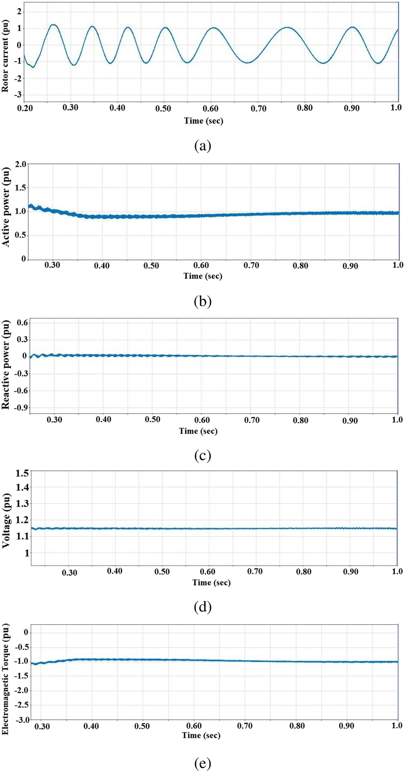
LVRT capability of DFIG without grid fault with the proposed controller: (a) rotor current, (b) real power, (c) reactive power, (d) DC-link voltage, and (e) electromagnetic torque.
5.2 Control performance during grid fault
The control performance of the proposed controller during voltage sag is shown in Figure 11, and the HIL setup is shown in Figure 8. Here, the hardware validation is shown for the proposed controller under the voltage sag condition. This sag is created for 100 ms, which is initiated at

LVRT capability of DFIG with the proposed controller under 60% voltage sag (i) and (g) stator voltage (ii) and (h) rotor current (iii) and (i) active power (iv) and (j) reactive power (v) and (k) DC-link voltage (vi) and (l) electromagnetic torque. (I) Simulation results. (II) HIL results.
Then, the reactive power varies from 0.6 to
The DFIG system under the fault has been discussed in three cases by comparing the first order SMC (FOSMC), second order SMC (SOSMC), and proposed controller. These cases are studied as follows:
Case A
Performance of the proposed FFN-SOSM controller in the DFIG system.
The LM-ST algorithm-based proposed controller with NN architecture

Proposed controller training on

Proposed controller training on
Meanwhile, in the error histogram, blue bars indicate the training data, green bars are validation data, and red bars represent testing data. The error histogram with 20 bins represents the target and predicted values after the training and can be seen in Figures 12(a) and 13(a). Substantially, validation performance plots the training errors, validation errors, and test errors with a small mean-square error (MSE). The best validation performance at 1,000 epoch is shown in Figures 12(b) and 13(b). Consider the regression, and the fit is reasonably good for the current data sets, which are above 0.93. The regression plots the output with target values with R close to unity, as shown in Figures 12(c) and 13(c). The 1,000 epochs increase the accuracy of the model and display the maximum number of iterations. The gradient measures the change in all weights regarding the change in error, mu parameter trains the NN and affects the error convergence, and val fail is a training parameter, which stops the poor performance of training data in NN. The training plots gradient, mu, and val fail with epochs are shown in Figures 12(d) and 13(d). Besides, the result samples of the proposed controller are shown in Table 4, and it shows the MSE, which reduces the computation time, and
Result samples of the proposed controller
| Parameters | Samples | MSE |
|
|---|---|---|---|
| Training | 140,001 |
|
|
| Validation | 30,000 |
|
|
| Testing | 30,000 |
|
|
Case B
Comparison of the proposed and SOSM controller.
The SOSM controller with the ST algorithm is insensitive to uncertainties and external disturbance. To overcome this drawback, the proposed controller is trained under the disturbance condition. According to equations (13)–(16), the system operates upon the LM-ST algorithm during the training process. The nearly 1,000 data samples are trained for accuracy and results are shown in Figures 12 and 13. Moreover, the comparison between the proposed and SOSM controller is shown in Figure 14, and also it is tabulated in Table 5. Here, peak values of the system parameters resulted during SOSM are reduced and improved the transient performance of the proposed controller under the sag.

Comparison of SOSM and proposed controller during LVRT capability of DFIG system during grid fault: (a) rotor current, (b) real power, (c) reactive power, (d) DC-link voltage, and (e) electromagnetic torque.
Comparison of the proposed controller with SOSMC
| Parameters | SOSMC (pu) | Proposed (pu) |
|---|---|---|
| Rotor current | 1.77 | 1.67 |
| Stator real power | 0.27 | 0.293 |
| Stator reactive power | −0.572 | −0.56 |
| Rotor speed | 1.225 | 1.22 |
| DC link voltage | 1.265 | 1.262 |
| Electromagnetic torque | −0.072 | −0.073 |
On the other side, harmonic distortion is more in the SOSM as compared to the proposed controller. The harmonic spectrum of signum and trainlm functions of the DFIG system due to FFT are shown in Figure 15. Here, total harmonic distortion (THD) of the SOSM controller obtained from the signum function’s square wave is more than 48% of the standard THD. But, the proposed controller provides less THD, as shown in Figure 15.
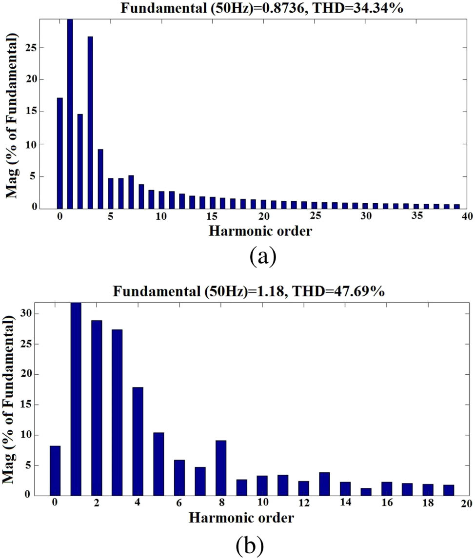
Harmonic spectrum: (a) FFN-SOSMC and (b) SOSMC.
Case C
Comparative study of the proposed and FOSM controller.
The switching function of FOSM controller is unable to overcome the chattering effect. The LM-ST algorithm-based proposed controller significantly reduces the chattering. The comparison between the proposed and FOSM controller can be seen in Figure 16, and also it is tabulated in Table 6. Interestingly, Figure 17 represents the different set of controllers with different algorithms under the voltage sag condition. Also, this chart indicates the effective percentage improvement of LVRT for different controllers.

Comparison of FOSM and proposed controller during LVRT capability of DFIG system during grid fault: (a) rotor current, (b) active power, (c) reactive power, (d) DC-link voltage, and (e) electromagnetic torque.
Comparison of the proposed controller with FOSMC
| Parameters | FOSMC (pu) | Proposed (pu) |
|---|---|---|
| Rotor current | 0.2 | 1.7 |
| Stator active power | 0.15 | 1 |
| Stator reactive power | 0 | −0.4 |
| DC link voltage | 1.120 | 1.250 |
| Electromagnetic torque | 0 | −1.7 |

Comparative study of efficient controllers.
6 Conclusion
This article proposed the FFN-SOSM controller using the LM-ST algorithm for the DFIG system under voltage sag. The perspective of the LVRT enhancement is analysed through the proposed controller, and the conclusions are drawn as follows:
The HIL (OPAL-RT 4510) results are closely matched with the simulation results, which are validation to the proposed controller under the voltage sag.
The model’s hardware RT-LAB interface and initial condition settings are mainly responsible for the approximate matching from the exact matching, while comparing the results.
The signum and trainlm functions have brought the modifications in the proposed controller and resulted in improving the system’s performance.
The LM-ST algorithm-based proposed controller improved the transient behaviour of certain machine parameters, such as real power, reactive power, rotor current, DC-link voltage, and electromagnetic torque under the voltage sag.
The proposed controller has suppressed the uncertainties, as it overcame the peak amplitude and harmonic distortion.
The stability analysis of the proposed controller contributed to enhancing the transient performance of the DFIG system.
The FFN-SOSM controller provided better results as compared to FOSMC and SOSMC.
LVRT enhancement is achieved with improved transient performance.
-
Conflict of interest: Authors state no conflict of interest.
References
[1] Blaabjerg F, Ma K. High power electronics: key technology for wind turbines. Power Electronics for Renewable Energy Systems, Transportation and Industrial Applications. Wiley Online Library; 2014. p. 136–59. 10.1002/9781118755525.ch6Search in Google Scholar
[2] Hiremath R, Moger T. Comprehensive review on low voltage ride through capability of wind turbine generators. Int Trans Electr Energy Sys. 2020;30(10):e12524. 10.1002/2050-7038.12524Search in Google Scholar
[3] Merabet A, Eshaft H, Tanvir AA, Power-current controller based sliding mode control for DFIG-wind energy conversion system. IET Renew Power Generat. 2018;12(10):1155–63. 10.1049/iet-rpg.2017.0313Search in Google Scholar
[4] Benbouzid M, Beltran B, Amirat Y, Yao G, Han J, Mangel H. Second-order sliding mode control for DFIG-based wind turbines fault ride-through capability enhancement. ISA Trans. 2014;53(3):827–33. 10.1016/j.isatra.2014.01.006Search in Google Scholar PubMed
[5] Xiong L, Li P, Wang J. High-order sliding mode control of DFIG under unbalanced grid voltage conditions. Int J Electr Power Energy Sys. 2020;117:105608. 10.1016/j.ijepes.2019.105608Search in Google Scholar
[6] Benbouhenni H. Neuro-sconde order sliding mode field oriented control for DFIG-based wind turbine. Int J Smart Grid. 2018;2(4):209–17. Search in Google Scholar
[7] Benbouhenni H. Sliding mode with neural network regulator for DFIG using two-level NPWM strategy. Iran J Electr Electron Eng. 2019;15(3):411–9. Search in Google Scholar
[8] Fdaili M, Essadki A, Nasser T. Comparative analysis between robust SMC & conventional PI controllers used in WECS based on DFIG. Int J Renew Energy Res. 2017;7(4):2151–61. Search in Google Scholar
[9] Ebrahimkhani S. Robust fractional order sliding mode control of doubly-fed induction generator (DFIG)-based wind turbines. ISA Trans. 2016;63:343–54. 10.1016/j.isatra.2016.03.003Search in Google Scholar PubMed
[10] Li S, Wang H, Tian Y, Aitouch A, Klein J. Direct power control of DFIG wind turbine systems based on an intelligent proportional-integral sliding mode control. ISA Trans. 2016;64:431–9. 10.1016/j.isatra.2016.06.003Search in Google Scholar PubMed
[11] Adouni A, Chariag D, Diallo D, Hamed MB, Sbita L. FDI based on artificial neural network for low-voltage-ride-through in DFIG-based wind turbine. ISA Trans. 2016;64:353–64. 10.1016/j.isatra.2016.05.009Search in Google Scholar PubMed
[12] Bakouri A, Mahmoudi H, Abbou A, Moutchou M. Optimizing the wind power capture by using dtc technique based on artificial neural network for a dfig variable speed wind turbine. In: 2015 10th International Conference on Intelligent Systems: Theories and Applications (SITA). IEEE; 2015. p. 1–7. 10.1109/SITA.2015.7358425Search in Google Scholar
[13] Din WU, Zeb K, Khan B, Ali S, Mehmood C, Haider A. Control of DC link voltage for grid interfaced DFIG using adaptive sliding mode & fuzzy based on Levenberg-Marquardt algorithm during symmetrical fault. In: 2016 International Conference on Computing, Electronic and Electrical Engineering (ICE Cube). IEEE; 2016. p. 148–53. 10.1109/ICECUBE.2016.7495213Search in Google Scholar
[14] Khan I, Zeb K, Uddin W, Ishfaq M, ul Islam S, Jan KU. Robust control design for DFIG-based wind turbine under voltage sags. In: 2020 3rd International Conference on Computing, Mathematics and Engineering Technologies (iCoMET). IEEE; 2020. p. 1–6. 10.1109/iCoMET48670.2020.9074103Search in Google Scholar
[15] Azeem B, Ullah Z, Rehman F, Ali S, Haider A, Saeed S, et al. Levenberg-marquardt SMC control of grid-tied doubly fed induction generator (DFIG) using FRT schemes under symmetrical fault. In: 2018 1st International Conference on Power, Energy and Smart Grid (ICPESG). IEEE; 2018. p. 1–6. 10.1109/ICPESG.2018.8384493Search in Google Scholar
[16] Howlader AM, Senjyu T. A comprehensive review of low voltage ride through capability strategies for the wind energy conversion systems. Renew Sustain Energy Rev. 2016;56:643–58. 10.1016/j.rser.2015.11.073Search in Google Scholar
[17] Saad NH, Sattar AA, AE-AM Mansour. Low voltage ride through of doubly-fed induction generator connected to the grid using sliding mode control strategy. Renew Energy. 2015;80:583–94. 10.1016/j.renene.2015.02.054Search in Google Scholar
[18] Atkinson D, Pannell G, Cao W, Zahawi B, Abeyasekera T, Jovanovic M. A doubly-fed induction generator test facility for grid fault ride-through analysis. IEEE Instrum Meas Mag. 2012;15(6):20–7. 10.1109/MIM.2012.6365539Search in Google Scholar
[19] Krause PC, Wasynczuk O, Sudhoff SD, Pekarek S. Analysis of electric machinery and drive systems. Vol. 2. John Wiley & Sons, IEEE Press; 2002. 10.1109/9780470544167Search in Google Scholar
[20] Yu H, Wilamowski BM. Levenberg-marquardt training. Ind Electron Handbook. 2011;5(12):1. 10.1201/b10604-15Search in Google Scholar
© 2021 Ravikiran Hiremath and Tukaram Moger, published by De Gruyter
This work is licensed under the Creative Commons Attribution 4.0 International License.
Articles in the same Issue
- Regular Articles
- Electrochemical studies of the synergistic combination effect of thymus mastichina and illicium verum essential oil extracts on the corrosion inhibition of low carbon steel in dilute acid solution
- Adoption of Business Intelligence to Support Cost Accounting Based Financial Systems — Case Study of XYZ Company
- Techno-Economic Feasibility Analysis of a Hybrid Renewable Energy Supply Options for University Buildings in Saudi Arabia
- Optimized design of a semimetal gasket operating in flange-bolted joints
- Behavior of non-reinforced and reinforced green mortar with fibers
- Field measurement of contact forces on rollers for a large diameter pipe conveyor
- Development of Smartphone-Controlled Hand and Arm Exoskeleton for Persons with Disability
- Investigation of saturation flow rate using video camera at signalized intersections in Jordan
- The features of Ni2MnIn polycrystalline Heusler alloy thin films formation by pulsed laser deposition
- Selection of a workpiece clamping system for computer-aided subtractive manufacturing of geometrically complex medical models
- Development of Solar-Powered Water Pump with 3D Printed Impeller
- Identifying Innovative Reliable Criteria Governing the Selection of Infrastructures Construction Project Delivery Systems
- Kinetics of Carbothermal Reduction Process of Different Size Phosphate Rocks
- Plastic forming processes of transverse non-homogeneous composite metallic sheets
- Accelerated aging of WPCs Based on Polypropylene and Birch plywood Sanding Dust
- Effect of water flow and depth on fatigue crack growth rate of underwater wet welded low carbon steel SS400
- Non-invasive attempts to extinguish flames with the use of high-power acoustic extinguisher
- Filament wound composite fatigue mechanisms investigated with full field DIC strain monitoring
- Structural Timber In Compartment Fires – The Timber Charring and Heat Storage Model
- Technical and economic aspects of starting a selected power unit at low ambient temperatures
- Car braking effectiveness after adaptation for drivers with motor dysfunctions
- Adaptation to driver-assistance systems depending on experience
- A SIMULINK implementation of a vector shift relay with distributed synchronous generator for engineering classes
- Evaluation of measurement uncertainty in a static tensile test
- Errors in documenting the subsoil and their impact on the investment implementation: Case study
- Comparison between two calculation methods for designing a stand-alone PV system according to Mosul city basemap
- Reduction of transport-related air pollution. A case study based on the impact of the COVID-19 pandemic on the level of NOx emissions in the city of Krakow
- Driver intervention performance assessment as a key aspect of L3–L4 automated vehicles deployment
- A new method for solving quadratic fractional programming problem in neutrosophic environment
- Effect of fish scales on fabrication of polyester composite material reinforcements
- Impact of the operation of LNG trucks on the environment
- The effectiveness of the AEB system in the context of the safety of vulnerable road users
- Errors in controlling cars cause tragic accidents involving motorcyclists
- Deformation of designed steel plates: An optimisation of the side hull structure using the finite element approach
- Thermal-strength analysis of a cross-flow heat exchanger and its design improvement
- Effect of thermal collector configuration on the photovoltaic heat transfer performance with 3D CFD modeling
- Experimental identification of the subjective reception of external stimuli during wheelchair driving
- Failure analysis of motorcycle shock breakers
- Experimental analysis of nonlinear characteristics of absorbers with wire rope isolators
- Experimental tests of the antiresonance vibratory mill of a sectional movement trajectory
- Experimental and theoretical investigation of CVT rubber belt vibrations
- Is the cubic parabola really the best railway transition curve?
- Transport properties of the new vibratory conveyor at operations in the resonance zone
- Assessment of resistance to permanent deformations of asphalt mixes of low air void content
- COVID-19 lockdown impact on CERN seismic station ambient noise levels
- Review Articles
- FMEA method in operational reliability of forest harvesters
- Examination of preferences in the field of mobility of the city of Pila in terms of services provided by the Municipal Transport Company in Pila
- Enhancement stability and color fastness of natural dye: A review
- Special Issue: ICE-SEAM 2019 - Part II
- Lane Departure Warning Estimation Using Yaw Acceleration
- Analysis of EMG Signals during Stance and Swing Phases for Controlling Magnetorheological Brake applications
- Sensor Number Optimization Using Neural Network for Ankle Foot Orthosis Equipped with Magnetorheological Brake
- Special Issue: Recent Advances in Civil Engineering - Part II
- Comparison of STM’s reliability system on the example of selected element
- Technical analysis of the renovation works of the wooden palace floors
- Special Issue: TRANSPORT 2020
- Simulation assessment of the half-power bandwidth method in testing shock absorbers
- Predictive analysis of the impact of the time of day on road accidents in Poland
- User’s determination of a proper method for quantifying fuel consumption of a passenger car with compression ignition engine in specific operation conditions
- Analysis and assessment of defectiveness of regulations for the yellow signal at the intersection
- Streamlining possibility of transport-supply logistics when using chosen Operations Research techniques
- Permissible distance – safety system of vehicles in use
- Study of the population in terms of knowledge about the distance between vehicles in motion
- UAVs in rail damage image diagnostics supported by deep-learning networks
- Exhaust emissions of buses LNG and Diesel in RDE tests
- Measurements of urban traffic parameters before and after road reconstruction
- The use of deep recurrent neural networks to predict performance of photovoltaic system for charging electric vehicles
- Analysis of dangers in the operation of city buses at the intersections
- Psychological factors of the transfer of control in an automated vehicle
- Testing and evaluation of cold-start emissions from a gasoline engine in RDE test at two different ambient temperatures
- Age and experience in driving a vehicle and psychomotor skills in the context of automation
- Consumption of gasoline in vehicles equipped with an LPG retrofit system in real driving conditions
- Laboratory studies of the influence of the working position of the passenger vehicle air suspension on the vibration comfort of children transported in the child restraint system
- Route optimization for city cleaning vehicle
- Efficiency of electric vehicle interior heating systems at low ambient temperatures
- Model-based imputation of sound level data at thoroughfare using computational intelligence
- Research on the combustion process in the Fiat 1.3 Multijet engine fueled with rapeseed methyl esters
- Overview of the method and state of hydrogenization of road transport in the world and the resulting development prospects in Poland
- Tribological characteristics of polymer materials used for slide bearings
- Car reliability analysis based on periodic technical tests
- Special Issue: Terotechnology 2019 - Part II
- DOE Application for Analysis of Tribological Properties of the Al2O3/IF-WS2 Surface Layers
- The effect of the impurities spaces on the quality of structural steel working at variable loads
- Prediction of the parameters and the hot open die elongation forging process on an 80 MN hydraulic press
- Special Issue: AEVEC 2020
- Vocational Student's Attitude and Response Towards Experiential Learning in Mechanical Engineering
- Virtual Laboratory to Support a Practical Learning of Micro Power Generation in Indonesian Vocational High Schools
- The impacts of mediating the work environment on the mode choice in work trips
- Utilization of K-nearest neighbor algorithm for classification of white blood cells in AML M4, M5, and M7
- Car braking effectiveness after adaptation for drivers with motor dysfunctions
- Case study: Vocational student’s knowledge and awareness level toward renewable energy in Indonesia
- Contribution of collaborative skill toward construction drawing skill for developing vocational course
- Special Issue: Annual Engineering and Vocational Education Conference - Part II
- Vocational teachers’ perspective toward Technological Pedagogical Vocational Knowledge
- Special Issue: ICIMECE 2020 - Part I
- Profile of system and product certification as quality infrastructure in Indonesia
- Prediction Model of Magnetorheological (MR) Fluid Damper Hysteresis Loop using Extreme Learning Machine Algorithm
- A review on the fused deposition modeling (FDM) 3D printing: Filament processing, materials, and printing parameters
- Facile rheological route method for LiFePO4/C cathode material production
- Mosque design strategy for energy and water saving
- Epoxy resins thermosetting for mechanical engineering
- Estimating the potential of wind energy resources using Weibull parameters: A case study of the coastline region of Dar es Salaam, Tanzania
- Special Issue: CIRMARE 2020
- New trends in visual inspection of buildings and structures: Study for the use of drones
- Special Issue: ISERT 2021
- Alleviate the contending issues in network operating system courses: Psychomotor and troubleshooting skill development with Raspberry Pi
- Special Issue: Actual Trends in Logistics and Industrial Engineering - Part II
- The Physical Internet: A means towards achieving global logistics sustainability
- Special Issue: Modern Scientific Problems in Civil Engineering - Part I
- Construction work cost and duration analysis with the use of agent-based modelling and simulation
- Corrosion rate measurement for steel sheets of a fuel tank shell being in service
- The influence of external environment on workers on scaffolding illustrated by UTCI
- Allocation of risk factors for geodetic tasks in construction schedules
- Pedestrian fatality risk as a function of tram impact speed
- Technological and organizational problems in the construction of the radiation shielding concrete and suggestions to solve: A case study
- Finite element analysis of train speed effect on dynamic response of steel bridge
- New approach to analysis of railway track dynamics – Rail head vibrations
- Special Issue: Trends in Logistics and Production for the 21st Century - Part I
- Design of production lines and logistic flows in production
- The planning process of transport tasks for autonomous vans
- Modeling of the two shuttle box system within the internal logistics system using simulation software
- Implementation of the logistics train in the intralogistics system: A case study
- Assessment of investment in electric buses: A case study of a public transport company
- Assessment of a robot base production using CAM programming for the FANUC control system
- Proposal for the flow of material and adjustments to the storage system of an external service provider
- The use of numerical analysis of the injection process to select the material for the injection molding
- Economic aspect of combined transport
- Solution of a production process with the application of simulation: A case study
- Speedometer reliability in regard to road traffic sustainability
- Design and construction of a scanning stand for the PU mini-acoustic sensor
- Utilization of intelligent vehicle units for train set dispatching
- Special Issue: ICRTEEC - 2021 - Part I
- LVRT enhancement of DFIG-driven wind system using feed-forward neuro-sliding mode control
- Special Issue: Automation in Finland 2021 - Part I
- Prediction of future paths of mobile objects using path library
- Model predictive control for a multiple injection combustion model
- Model-based on-board post-injection control development for marine diesel engine
- Intelligent temporal analysis of coronavirus statistical data