Development of Smartphone-Controlled Hand and Arm Exoskeleton for Persons with Disability
-
 ,
,

Abstract
This study addresses the need for assistive technology of people who lost control of their upper limbs as well as people who are undergoing rehabilitation. Loss of upper limb control causes lack of functionality and social acceptability especially for many people in developing countries with fewer available technology. The study develops a modern but low-cost prosthetic device that can be controlled by users using a smartphone and can be rapidly manufactured using three-dimensional printing (3D printing) of plastic materials. The development of the prosthetic device includes designing the mechanical and electronic parts, programming the Arduino board and Android application for control, simulation and analysis of 3D printed parts most subjected to stress, and 3D printing the parts under different settings. The device was tested in terms of time spent and capacity of lifting varying loads when not worn and when worn by users. The device can effectively lift 500 grams of load in one second for a person weighing between 50 to 60 kilograms.
1 Introduction
1.1 Project Background
Persons with disabilities are people whose ability to respond, to react or to move is less or restricted because of health problems caused by illnesses, accidents, etc. [1]. Persons with disabilities may have long-term physical, mental, intellectual, or sensory impairments who usually live along with various barriers in their environment and in society. These barriers hinder their full and effective participation in society and their access to basic needs and services [2].
Based on the latest report of the World Health Organization in 2011, around 15% of the world population or more than one billion people are estimated to live with some form of disability. According to the World Health Survey around 785 million people or 15.6% of the world population in 2011 that are 15 years and older live with a disability. Among them, 110 million people or 2.2% have very significant difficulties in functioning. With several physical and social barriers that persons with disabilities must live with, they tend to have lower educational achievements, less economic participation, and higher rates of poverty. Nations are then suggested to implement policies and to create enabling environment to address these barriers. The World Health Organization laid out nine recommendations for actions on overcoming barriers on disability, and the ninth recommendation is to strengthen and support research on disability [3].
In the Philippines, there is 12% prevalence of severe disability among 15 years and older based on the 2016 National Disability Prevalence Survey by the Philippine Statistics Authority. Prevalence of severe disability is highest among individuals who are 60 years old and older at 32% and least among people aged 15 to 39 years old at 6%. Access to education and work pose problem to up to 34% of persons with severe disability. Among persons with moderate to severe disability who reported considerable levels of unmet needs, one percent to eight percent report needing additional assistance [4].
This present study addresses the need for assistive technology of people who lost control of their upper limbs as well as people who are undergoing rehabilitation. Loss of upper limb control causes lack of functionality and social acceptability for many people around the world especially in developing countries with fewer available technology like the Philippines.
Modern prosthetic devices for the upper limbs can provide greater dexterity with provisions for complex actions. These modern devices are controlled with a wide range of commands that may be based on movement, neural activity, or other means. The control of modern prosthetic hand devices is typically based on surfaceelectromyogram that provides information regarding the neural activity of the user to the muscles [5]. However, this technology requires complex programming and manufacturing techniques that lead to expensive prototypes which are inaccessible to most people with physical disability. The study develops a modern but low-cost prosthetic device that can be controlled by users using a smartphone and can be rapidly manufactured using three-dimensional printing (3D printing) of polymer materials.
1.2 Objectives of the Project
The main objective of the study is to develop a low-cost, smartphone-controlled prosthesis for people with one-hand muscular disability. The prosthesis must allow users to lift their arms, to close and open their hands, and to carry a load of up to 1 kilogram. Three-dimensional printing using polymer materials must be employed for rapid prototyping and low-cost manufacturing of the device.
1.3 Project Scope and Limitations
Table 1 presents the various types of upper limb prostheses that are currently in use or under development. The upper limb prosthesis being developed in this study falls under the battery powered type that is switch-controlled through the connected smartphone. The disadvantages of this type of upper limb prosthesis include heavy weight and expensive cost which the study addresses by using lightweight and low-cost 3D printing materials.
Various Types of Upper Limb Prosthesis [6]
| Type | Advantages | Disadvantages |
|---|---|---|
| Cosmetic | Most lightweight, best cosmetics, less harnessing | High cost if custom-made, least function, low-cost glove stains easily |
| Body Powered | Moderate cost, moderately lightweight, most durable, highest sensory feedback, variety of prehensors available for various activities | Requires body movement which may be complex, requires uncomfortable harness, unsatisfactory appearance, increased energy expenditure |
| Battery Powered (myoelectric or switch controlled) | Moderate or no harnessing, least body movement needed to operate, moderate cosmetics, more function-proximal areas, stronger grasp in some cases | Heaviest, most expensive, high maintenance, limited sensory feedback, extended therapy time for training |
| Hybrid | All-cable excursion to elbow, low effort to position, low maintenance | Harder to lift but good for elbow disarticulation,lower pinch for TD and least cosmetic |
J. Gibbard reported that powered upper limb prostheses cost around 15,000 USD to 100,000 USD which makes high cost one of the potential factors why these devices have low acceptability among users [7]. Polisiero et al. reported the design and development of a low-cost battery-powered prosthetic hand with myoelectric control that is made of an aluminum skeleton and powered by DC motors. Though the device was built with minimum features, it was reported to be effective with readily available low-cost components [8]. The present study develops a powered upper limb prosthetics but switch-controlled using 3D printing polymer materials instead of conventional materials to limit its cost to 400 USD and to decrease its weight.
Meanwhile, the study keeps the advantages of this type of prosthesis by requiring no body movement from the disabled arm, acceptable cosmetics and more function-proximal areas. The present device also adds the advantage of customizability through 3D printing for different users which commercially available upper limb prostheses lack.
Despite its advantages of lighter weight and lower cost, the device being developed has its limitations in terms of motion. The device is limited to hand grasping, hand closing, hand opening and arm lifting with the elbow as the axis point. These motions are limited to some preset conditions like fixed shoulder joint and bending angle for the wrist and finger joints. Complex hand movements as well as sudden and powerful movements cannot be facilitated due to the design of the mechanical parts and the 3D printing materials.
In terms of control, the device is controllable by using a smartphone with touch buttons that can be held using the other hand of the user or by another person. With this, the device is primarily intended for users with one-arm disability. The device can also be worn by the user with another person controlling the device.
2 Related Projects and Studies
Upper limb prosthesis can be passive with cosmetic as its primary purpose, or active with movement of the arms and hands similar to natural human movements as the primary functions. Most upper limb prostheses under development today are battery-powered and myoelectric-controlled [5]. Very few studies explore switch-controlled protheses, but they are still in consideration because of lower cost and simplicity in design and operation. Though most studies and development are focused on myoelectric-controlled prothesis, the present study explores and advances the features of switch-controlled prosthesis by integrating 3D printing for manufacturing the parts and using a smart-phone for control. Lower cost, greater portability and customizability are the primary considerations in adopting the switch-controlled, battery-powered prothesis design to make the device accessible to many persons with disability in developing countries.
Table 2 compares the present device to upper limb devices that are presently in development. Most of these devices are meant to serve as orthosis or for the correction of disorders of the limbs as well as for therapy for correcting the movements of the limbs. The device developed in this study is intended as prosthesis for persons with upper limb disability and can also be used for therapeutic purposes. In terms of mobility, there are devices designed to be stationary since they are intended for upper limb therapy. Meanwhile, devices designed for orthosis and prosthesis must be portable and lightweight. Materials used for these devices are usually metal integrated with plastic materials to ensure durability, but it often results to heavier weight. In the case of the present study, materials to be used are 3D printing polymer materials to ensure lighter weight and customizability of the device. The present study differs from other available designs with the use of a smartphone for control.
Comparison of different devices and existing studies for arm therapy and orthosis
| Device | Developer | Use | Mobility | Material | Control |
|---|---|---|---|---|---|
| Center for Intelligent Mechatronics Upper Limb Orthosis [9] | Vanderbilt University (United States) | Orthosis and Therapy | Portable | Plastic | N/A |
| Titan Arm [10] | University of Pennsylvania (United States) | Orthosis and Therapy | Portable | Metal | Joystick |
| Maryland Ggeorgetown Army Exoskeleton [11] | University of Maryland (United States) | Therapy | Stationary | Metal | Force Sensors |
| Wearable Orthosis for Tremor Assessment & Suppression (WOTAS) [12] | Group of Bioengineering in Institute of Automatic Industry (Spain) | Therapy and Diagnostic | Stationary | Metal | Force Sensors |
| Myopro [13] | Axiobionics, LLC (United States) | Orthosis and Theraphy | Portable | Metal and Plastic | Electromyogram |
| AGAPAY Project [14] | De La Salle University and University of the Philippines (Philippines) | Therapy | Stationary | Metal and Plastic | Electromyogram |
| Present Study | Bataan Peninsula State University (Philippines) | Prosthesis and Theraphy | Portable | 3D Prining Plastic | Smartphone Touch Buttons |
3 Methodology
3.1 Design Stage
The project starts with collecting data on anatomical sizing of the human hand and arms for an ergonomic design. Data on the sizes of arms and hands were based on the work of Zafar et al. [15] and were used for the initial design of the prototype using computer-aided design software. The average weight of a human body is assumed 61.3 kilograms for males and 54.3 kilograms for females [16], but the study considered the average body weight for males. An average weight of a human arm is about 5.3% of the body weight which gave about 3.25 kilograms. Meanwhile, the weight of the hand and forearm of an average person is 2.52% of the bodyweight or 1.54 kilograms and the average length is around 63.5 centimeters [? ]. This set of data was used for the calculation of motor power needed.
Actual measurements of the arm and hand sizes of persons with disability were not readily available and were not collected. The final design of the device was worn and tested by abled persons and was not tested by persons with upper limb disability to avoid injuries since the device is still in its initial development stage. Further development of the device may require taking actual arm and hand measurements from persons with upper limb disability. In that case, the arm and hand sizes can be readily adjusted in the design software as well as in the actual prototype using 3D printing.
The movement of the arm actuator and finger segments assembly as shown in Figure 1 and Figure 2 was then decided with simplicity in design and unobstructed transmission of motion as primary considerations. For the lifting motion of the lower arm actuator through the elbow joint, a worm gear system that connects the geared lower arm actuator to the motor was considered because of the need for high torque and slow motion. For the grasping motion of the fingers, a string system connecting each of the wearable finger ring segment to the motor was used.
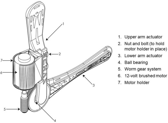
Computer-aided design of arm actuator assembly

Finger ring segment and thumb support
Two motors are used in the device: one 12-volt brushed motor for the lifting motion of the lower arm actuator using a worm gear system and one 360-degree servomotor for the grasping motion of the fingers using string connection. A control unit that directs the rotation of the 12-volt brushed motor to either clockwise or counter-clockwise to raise or drop the lower arm actuator was designed as presented in Figure 2 and Figure 4. This system uses a series of relay switches to reverse the rotation of the motor and installs a limit switch to prevent the over rotation of the arm.
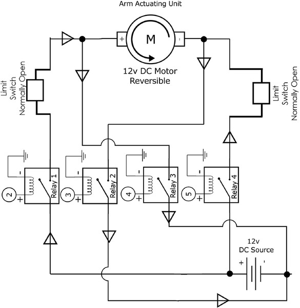
Circuit diagram for the motor-worm gear assembly for the arm lifting motion

Flow chat of the program for the Arduino control module
Part of the design stage was programming the sensors and actuators in the Arduino board, and the flow chart of the program is shown in Figure 4. Input values in the smart-phone is transmitted to the Arduino program and is converted to commands to control the motors for actuating the device.
Using the Arduino board, the device will be connected via Bluetooth to the smartphone with an installed Android mobile application. The program flow chart of the Android application that must be installed in the smartphone to connect it to the device and to control the device is presented in Figure 5. The Android application was designed using the Massachusetts Institute of Technology (MIT)App Inventor. Figure 6 shows the user interface of the Android application that is divided into the main screen for directly controlling the device and the information screen. The user interface has options for raising and lowering the lower arm actuator of the device through the “ARM+” and “ARM–“ touch buttons. The user interface also has options for controlling the grasping motion of the finger ring segments through the “HAND+” and“HAND– “ touch buttons. The primary considerations in choosing the Arduino board and the Android application are lower cost, simplicity in programming and accessibility to most users.

Flow chart of the Android application installed in the smartphone for control

User interface of the Android application installed in the smartphone for control
3.2 Simulation Stage
The finite element analysis of the 3D printed parts of the device was done in SolidWorks. The bases in the analysis were printability in 3D printers, print volume and strength of the material and design. Printability in 3D printers can be achieved by eliminating complicated curves and shapes that may lead to frequent printing failure. Print volume must be decreased as much as possible to lower the printing cost and the print time while considering the structural integrity of the parts.
The materials considered for the 3D printing of the parts of the device are acrylonitrile butadiene styrene (ABS) plastic filament and polylactic acid (PLA) plastic filament. Parts that are frequently subjected to friction and heat is printed using ABS plastic filament because of its high heat capacity. The parts subjected to finite element analysis were the lower arm actuator and the finger ring segment that were simulated using ABS plastic material.
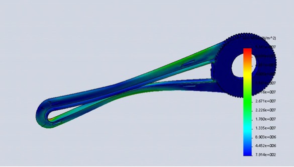
Two designs were prepared and simulated for the lower arm actuator and for the finger ring segment since these parts are the most subjected to load and stress. The lower arm actuator was subjected to 10 kilogram-force acting downward at two points which are the mid-section and left-most section of the lower arm actuator. The fixed points were set at the right-most section and along the perimeter of the hole in the toothed section of the actuator. The first design in Figure 7 experiences less stress but has higher print volume. Removing the webbed internal part as shown in the second design in Figure 8 causes the material to squeeze inward. Therefore, the first design has higher structural integrity.

First design prepared and simulated for the lower arm actuator part
Second design prepared and simulated for the lower arm actuator part
The two designs of the finger ring segment that were prepared for simulation and analysis are presented in Figure 9 and Figure 10. The material was subjected to 5 kilogram-force acting downward at two points which are in the narrow area near the holes in the upper-most sections of the finger ring segment. The fixed points were set in the middle of the flat area in the bottom section of the material. In the first design as shown in Figure 9, the thinnest part of the material is subjected to higher stress and may cause structural failure. The second design as shown in Figure 10 is almost similar with the first design but with thicker walls. This is to disperse stress and to ensure less chance of breaking although it increases the print volume of the material.

First design prepared and simulated for the finger ring segment

Second design prepared and simulated for the finger ring segment
3.3 Prototyping Stage
Since most parts of the device like the upper and lower arm actuator are larger than the print beds of the 3D printer, they were sliced into smaller parts for printing and were then glued together using cyanoacrylate adhesive.
Half of the lower arm actuator and other parts of the device were printed using Flash Forge Creator Pro and PLA plastic filament under standard print setting with 0.18-millimeter (0.18-mm) layer height and 80% infill. As shown in Figure 11 and Figure 12, the other end of the lower arm actuator which experiences the highest stress were printed using Zortrax M200 under fine print setting with 0.09-millimeter (0.09-mm) layer height and 100% infill.
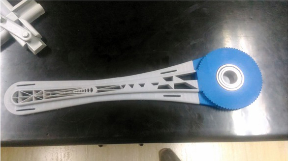
Two parts of the lower arm actuator printed using different materials
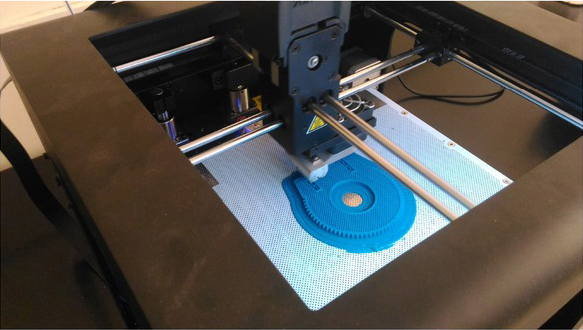
Printing of the worm gear under high settings
Different printing settings were used and tested in 3D printing the worm gear to ensure optimal strength and exact measurements as shown in Table 3. Results of the test print under different settings are shown in Figure 13 using
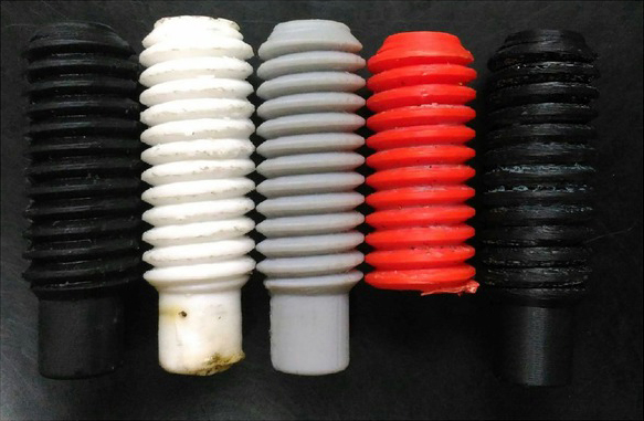
Worm gears printed under different printing settings
Analysis of worm gear print quality under different settings
| Printer | Print Settings | Remarks |
|---|---|---|
| FlashForge Creator Pro | Standard print, 0.18-mm layer height, PLA plastic filament, 100% infill, auto-support, vertical orientation | Prominent vibration in the device due to rough edges of the worm gear. Rough edges were due to the print support and layer height. |
| Hyperprint, 0.09-mm layer height, PLA plastic filament, 100% infill, auto-support, vertical orientation | Eccentric shape of the worm that did not fit the geared end of the lower arm actuator | |
| Zortrax M200 | Standard print, 0.18-mm layer height, ABS plastic filament, maximum infill, auto-support, 40∘ vertical orientation | Loose thread after several test due to friction and heat Heat from friction melted the 0.18-mm layer height of the print |
| Fine print, 0.09-mm layer height, ABS plastic filament, maximum infill, auto-support, 40∘horizontal orientation | Loose thread due to friction and heat that may damage the device after several use | |
| Fine print, 0.09-mm layer height, ABS plastic filament, maximum infill, auto-support, 40∘ vertical orientation | Small amount of vibration in the device that migh be suitable for long-time use | |
| Ultimaker 3+ | Standard print, 0.18-mm layer height, PC plastic filament, maximum infill, auto-support, 40∘ vertical orientation | Poor print quality that might lead to easy wear of the device |
| Forms 2 SLA | Standard print, 0.18-mm layer height, black standard resin, horizontal orientation | Support structures in the print were difficult to remove that created rough edges of the worm gear. Brittle print with obvious lower strength. |
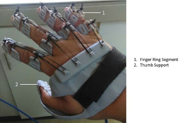
Finger ring segments and thumb support assembly
Forms 2, Ultimaker PC, Creator Pro, Zortax HD, Zortrax Std (from left to right in the picture).
The 3D-printed parts, motors, mechanical components, and electronic components are then assembled. Cushions, straps, and supports were fitted in the device for the optimal comfort of users wearing the device.

Upper and lower arm actuators assembly
4 Testing and Discussion of Results
The tests conducted for the device were the control load test, the live load test and the battery discharge rate test.
The control load test recorded the time it took for the device to lift varying amount of load from no load to 1000 g. Each load constituted a test run with three trials each run, and the average value was recorded as shown in the graph in Figure 16. The results indicated that without carrying any load, the lower arm actuator of the device could be completely lifted in 0.6 second. Meanwhile, the device was able to lift the maximum load of 1000 grams in 0.9 second. There was no significant difference in lifting time as the load varies from no load to 1000 grams.
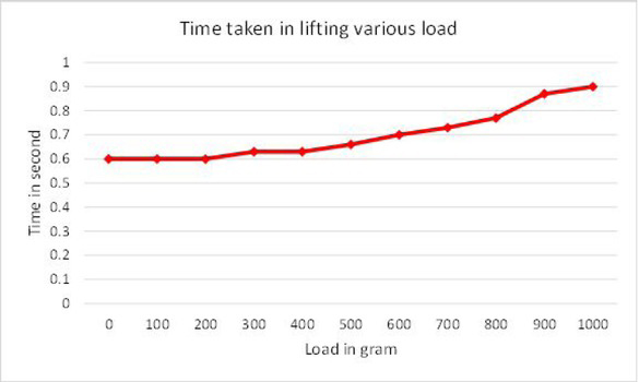
Graph of control load test results
The live load test was conducted with varying amount of load that were zero load, 500-gram load and 1000-gram load while being worn by abled users with varying weight from 40 kilograms to 90 kilograms. The test result is presented in the graph in Figure 16. Under varying weight of the users that is proportional to the arm weight, the lower arm actuator behaved inconsistently when worn by users with 54-kilogram weight and higher. There is also significant difference in the lifting time of the lower arm actuator when different loads are carried by the device and when worn by different user of varying weight. The device failed to lift the 1000-gram load when worn by the 84-kilogram and 90-kilogram users due to higher arm weight of the users. The present design of the device is best suited for users with weight around 50 kilograms and could carry at most 500-gram load.
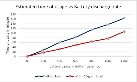
The battery discharge rate test recorded the estimated time of usage of the device under the no-load and 400-gram-load conditions as the battery was discharging power in the interval of 200 milliampere-hour as shown in the graph in Figure 18.
The device has longer time of usage under the no-load condition in which 25 minutes of usage consumes around 200 milliampere-hour of 1% of the power capacity of the installed battery. By extrapolating the available data, the 20,000-miliAmpere-hour battery integrated in the device can power the device continuously for at least 40 hours under no load. With 400-gramload, the device can be powered continuously by the integrated battery for at least 25 hours.
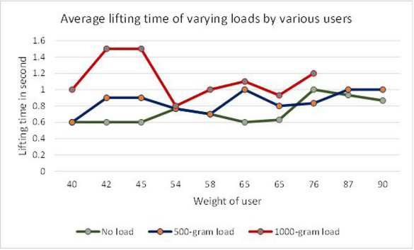
Graph of live load test results
Graph of battery discharge rate vs time of usage
5 Conclusion and Recommendation
The present study develops a modern but low-cost prosthetic device that allows users with upper limb disability to lift their hands and to carry up to 1-kilogram load. The device can be controlled using a smartphone and can be rapidly manufactured using 3D printing of polymer materials that can limit its cost to 400 USD, decrease its weight, and offer customizability for users which commercially available prostheses lack.
The development of the device includes designing the mechanical and electronic parts, programming the Arduino board and Android application for control, simulation and analysis of 3D printed parts, and 3D printing the parts. The operation of the device is facilitated by the battery-powered motors, worm gear system, and string system. The device uses sensors and actuators in the Arduino board that connects the device via Bluetooth to the smart-phone with an installed Android mobile application.
The finite element analysis of the 3D printed parts was done to analyze the printability in 3D printers, print volume and strength of the material and design. The parts subjected to analysis were the lower arm actuator and the finger ring segment using ABS plastic material. For the lower arm actuator, the design with the webbed internal part that reduces stress was selected for printing. For the finger ring segment, the design with thicker walls that enable the dispersion of stress was selected. The designs have higher print volume but offer greater strength.
Most parts of the device were printed into smaller parts and were then glued together using cyanoacrylate adhesive. The parts of the device that are subjected to lower stress were printed using Flash Forge Creator Pro and PLA plastic filament under standard print setting with 0.18-millimeter layer height and 80% infill. Parts that are subjected to the highest stress were printed using Zortrax M200 under fine print setting with 0.09-millimeter layer height and 100% infill. The worm gear that transmits power from the motor to the actuators was 3D printed under different settings to find out the best setting for print-ability, stability during operation and exactness of dimensions. Using Zortrax M200 and ABS plastic filament under fine print setting, 0.09-mm layer height, maximum infill, auto-support and 40∘ vertical orientation yielded the best result. The worm gear under this setting experienced no print failure and produced less vibration during operation.
Based on the results of the control load and live load tests, the device can lift 500 grams of load for persons weighing between 50 to 60 kilograms. With this capacity, the device is best suggested for use as physical therapy assistive device for persons with upper limb disability. Considering the battery integrated in the device, it can be operated continuously for at least 40 hours with no load and for at least 25 hours with 400-gram load.
Improvements in the electronic components and programmable control are recommended. Advanced sensors such as accelerometer and voice activation can still be incorporated in the programmable control to increase accessibility for users. For the electronic components, devices that can sense the position of the arm can be fitted to provide smoother movement. The use of a lighter battery like lithium polymer instead of lead acid and the use of lighter motors are also recommended to decrease the overall weight of the device.
It is recommended for finger segments to be connected with individual servomotor for individual control of each finger. The fixed thumb support must be made movable and not fixed. Redesigning the finger segments and the thumb support would realistically enable the complex grasping motion. Adding more degree of freedom to the joints in the arm, the shoulder, shoulder blade and the wrist would largely improve the design of the device.
Acknowledgement
The 3D printers and 3D printing materials used in this study were provided by the Additive Manufacturing Research Laboratory (AMReL) of the Bataan Peninsula State University. AMReL is a joint project of the Department of Science and Technology - Philippine Council for Industry, Energy, and Emerging Technology Research and Development (DOST-PCIEERD) and the Bataan Peninsula State University (BPSU). The authors would like to thank Prof. John Ryan C. Dizon and Mr. Ray Noel M. Delda for assistance in 3D printing parts of the prosthesis. The participation to the 2019 International Conference on Materials Science and Engineering for paper presentation is sponsored by the provincial government of Bataan and the city government of Balanga.
References
[1] Disabled World [Internet]. Disabled World; c2004-2020 [cited 2019 Dec 20]. Disabilities: Definition, Types and Models of Disability. Available from https://www.disabled-world.com/disability/types/Search in Google Scholar
[2] United Nations Convention on the Rights of Persons with Disabilities. Article 1: Purpose. 2006.Search in Google Scholar
[3] World Health Organization. Summary: World Report On Disability. Malta; 2011.Search in Google Scholar
[4] Philippine Statistics Authority. 2016 National Diability Prevalende Survey. Manila; 2019.Search in Google Scholar
[5] Kumar DK, Jelfs B, Suib X, Arjunan SP. Prosthetic hand control: A multidisciplinary review to identifystrengths, shortcomings, and the future. Biomedical Signal Processing and Control. 2019;53:1-31.10.1016/j.bspc.2019.101588Search in Google Scholar
[6] Arjunan SP, Kumar DK, Bueno L, Villarejo-Mayor J, Bastos-Filho TF. Devices for Mobility and Manipulation for People with Reduced Abilities (Rehabilitation Science in Practice Series). In: Upper Limb Prosthesis Devices. Ohio: CRC Press; 2014.10.1201/b16870Search in Google Scholar
[7] Gibbard J. Open Hand Project. 2018.Search in Google Scholar
[8] Polisiero M. Design and assessment of a low-cost, electromyographically controlled, prosthetic hand. Medical Devices: Evidence and Research. 6(1):97-104Search in Google Scholar
[9] Gasser BW, Goldfarb M. Design and Performance Characterization of a Hand Orthosis Prototype to Aid Activities of Daily Living in a Post-Stroke Population. Proceedings of IEEE International Conference of Engineering in Medicine and Biology Society; August 2015.10.1109/EMBC.2015.7319240Search in Google Scholar PubMed
[10] MathWorks [Internet]. The Mathworks, Inc.; c1994-2020 [cited 2019 Dec 20]. Technical Articles and Newsletters: Winning the Cornell Cup Student Competition with a Robotic Arm Exoskeleton. Available from https://www.mathworks.com/company/newsletters/articles/winning-the-cornell-cup-student-competition-with-a-robotic-arm-exoskeleton.htmlSearch in Google Scholar
[11] Space Systems Laboratory [Internet]. University of Maryland, College Park; c2018 [cited 2019 Dec 20]. Exoskeleton. Available from https://ssl.umd.edu/exoskeletonSearch in Google Scholar
[12] Rocon E, Belda-Lois JM, Ruiz AF, Manto M, Moreno JC, Pons JL. Design and Validation of a Rehabilitation Robotic Exoskeleton for Tremor Assessment and Suppression. IEEE Transactions on Neural Systems and Rehabilitation Engineering. 2007.10.1109/TNSRE.2007.903917Search in Google Scholar PubMed
[13] Myomo.Com [Internet]. Myomo Inc.; c2018 [cited 2019 Dec 20]. What is a MyoPro Orthosis? Available from https://myomo.com/what-is-a-myopro-orthosis/Search in Google Scholar
[14] 4 Filipino scholars to pursue doctorate studies in UK. Manila Bulletin. 2018 Jan 13.Search in Google Scholar
[15] Zafar U, Rahman SU, Hamid N. Correlation between height and hand size, and predicting height on the basis of age, gender and hand size. Journal of Medical Sciences (Peshawar). 2017 Oct; 25(4):425-428.Search in Google Scholar
[16] ExRx.net [Internet]. ExRx; c1999-2020 [cited 2019 Dec 20]. Body Segment Data. Available from https://www.exrx.net/Kinesiology/SegmentsSearch in Google Scholar
© 2021 J-R. R. Diego et al., published by De Gruyter
This work is licensed under the Creative Commons Attribution 4.0 International License.
Articles in the same Issue
- Regular Articles
- Electrochemical studies of the synergistic combination effect of thymus mastichina and illicium verum essential oil extracts on the corrosion inhibition of low carbon steel in dilute acid solution
- Adoption of Business Intelligence to Support Cost Accounting Based Financial Systems — Case Study of XYZ Company
- Techno-Economic Feasibility Analysis of a Hybrid Renewable Energy Supply Options for University Buildings in Saudi Arabia
- Optimized design of a semimetal gasket operating in flange-bolted joints
- Behavior of non-reinforced and reinforced green mortar with fibers
- Field measurement of contact forces on rollers for a large diameter pipe conveyor
- Development of Smartphone-Controlled Hand and Arm Exoskeleton for Persons with Disability
- Investigation of saturation flow rate using video camera at signalized intersections in Jordan
- The features of Ni2MnIn polycrystalline Heusler alloy thin films formation by pulsed laser deposition
- Selection of a workpiece clamping system for computer-aided subtractive manufacturing of geometrically complex medical models
- Development of Solar-Powered Water Pump with 3D Printed Impeller
- Identifying Innovative Reliable Criteria Governing the Selection of Infrastructures Construction Project Delivery Systems
- Kinetics of Carbothermal Reduction Process of Different Size Phosphate Rocks
- Plastic forming processes of transverse non-homogeneous composite metallic sheets
- Accelerated aging of WPCs Based on Polypropylene and Birch plywood Sanding Dust
- Effect of water flow and depth on fatigue crack growth rate of underwater wet welded low carbon steel SS400
- Non-invasive attempts to extinguish flames with the use of high-power acoustic extinguisher
- Filament wound composite fatigue mechanisms investigated with full field DIC strain monitoring
- Structural Timber In Compartment Fires – The Timber Charring and Heat Storage Model
- Technical and economic aspects of starting a selected power unit at low ambient temperatures
- Car braking effectiveness after adaptation for drivers with motor dysfunctions
- Adaptation to driver-assistance systems depending on experience
- A SIMULINK implementation of a vector shift relay with distributed synchronous generator for engineering classes
- Evaluation of measurement uncertainty in a static tensile test
- Errors in documenting the subsoil and their impact on the investment implementation: Case study
- Comparison between two calculation methods for designing a stand-alone PV system according to Mosul city basemap
- Reduction of transport-related air pollution. A case study based on the impact of the COVID-19 pandemic on the level of NOx emissions in the city of Krakow
- Driver intervention performance assessment as a key aspect of L3–L4 automated vehicles deployment
- A new method for solving quadratic fractional programming problem in neutrosophic environment
- Effect of fish scales on fabrication of polyester composite material reinforcements
- Impact of the operation of LNG trucks on the environment
- The effectiveness of the AEB system in the context of the safety of vulnerable road users
- Errors in controlling cars cause tragic accidents involving motorcyclists
- Deformation of designed steel plates: An optimisation of the side hull structure using the finite element approach
- Thermal-strength analysis of a cross-flow heat exchanger and its design improvement
- Effect of thermal collector configuration on the photovoltaic heat transfer performance with 3D CFD modeling
- Experimental identification of the subjective reception of external stimuli during wheelchair driving
- Failure analysis of motorcycle shock breakers
- Experimental analysis of nonlinear characteristics of absorbers with wire rope isolators
- Experimental tests of the antiresonance vibratory mill of a sectional movement trajectory
- Experimental and theoretical investigation of CVT rubber belt vibrations
- Is the cubic parabola really the best railway transition curve?
- Transport properties of the new vibratory conveyor at operations in the resonance zone
- Assessment of resistance to permanent deformations of asphalt mixes of low air void content
- COVID-19 lockdown impact on CERN seismic station ambient noise levels
- Review Articles
- FMEA method in operational reliability of forest harvesters
- Examination of preferences in the field of mobility of the city of Pila in terms of services provided by the Municipal Transport Company in Pila
- Enhancement stability and color fastness of natural dye: A review
- Special Issue: ICE-SEAM 2019 - Part II
- Lane Departure Warning Estimation Using Yaw Acceleration
- Analysis of EMG Signals during Stance and Swing Phases for Controlling Magnetorheological Brake applications
- Sensor Number Optimization Using Neural Network for Ankle Foot Orthosis Equipped with Magnetorheological Brake
- Special Issue: Recent Advances in Civil Engineering - Part II
- Comparison of STM’s reliability system on the example of selected element
- Technical analysis of the renovation works of the wooden palace floors
- Special Issue: TRANSPORT 2020
- Simulation assessment of the half-power bandwidth method in testing shock absorbers
- Predictive analysis of the impact of the time of day on road accidents in Poland
- User’s determination of a proper method for quantifying fuel consumption of a passenger car with compression ignition engine in specific operation conditions
- Analysis and assessment of defectiveness of regulations for the yellow signal at the intersection
- Streamlining possibility of transport-supply logistics when using chosen Operations Research techniques
- Permissible distance – safety system of vehicles in use
- Study of the population in terms of knowledge about the distance between vehicles in motion
- UAVs in rail damage image diagnostics supported by deep-learning networks
- Exhaust emissions of buses LNG and Diesel in RDE tests
- Measurements of urban traffic parameters before and after road reconstruction
- The use of deep recurrent neural networks to predict performance of photovoltaic system for charging electric vehicles
- Analysis of dangers in the operation of city buses at the intersections
- Psychological factors of the transfer of control in an automated vehicle
- Testing and evaluation of cold-start emissions from a gasoline engine in RDE test at two different ambient temperatures
- Age and experience in driving a vehicle and psychomotor skills in the context of automation
- Consumption of gasoline in vehicles equipped with an LPG retrofit system in real driving conditions
- Laboratory studies of the influence of the working position of the passenger vehicle air suspension on the vibration comfort of children transported in the child restraint system
- Route optimization for city cleaning vehicle
- Efficiency of electric vehicle interior heating systems at low ambient temperatures
- Model-based imputation of sound level data at thoroughfare using computational intelligence
- Research on the combustion process in the Fiat 1.3 Multijet engine fueled with rapeseed methyl esters
- Overview of the method and state of hydrogenization of road transport in the world and the resulting development prospects in Poland
- Tribological characteristics of polymer materials used for slide bearings
- Car reliability analysis based on periodic technical tests
- Special Issue: Terotechnology 2019 - Part II
- DOE Application for Analysis of Tribological Properties of the Al2O3/IF-WS2 Surface Layers
- The effect of the impurities spaces on the quality of structural steel working at variable loads
- Prediction of the parameters and the hot open die elongation forging process on an 80 MN hydraulic press
- Special Issue: AEVEC 2020
- Vocational Student's Attitude and Response Towards Experiential Learning in Mechanical Engineering
- Virtual Laboratory to Support a Practical Learning of Micro Power Generation in Indonesian Vocational High Schools
- The impacts of mediating the work environment on the mode choice in work trips
- Utilization of K-nearest neighbor algorithm for classification of white blood cells in AML M4, M5, and M7
- Car braking effectiveness after adaptation for drivers with motor dysfunctions
- Case study: Vocational student’s knowledge and awareness level toward renewable energy in Indonesia
- Contribution of collaborative skill toward construction drawing skill for developing vocational course
- Special Issue: Annual Engineering and Vocational Education Conference - Part II
- Vocational teachers’ perspective toward Technological Pedagogical Vocational Knowledge
- Special Issue: ICIMECE 2020 - Part I
- Profile of system and product certification as quality infrastructure in Indonesia
- Prediction Model of Magnetorheological (MR) Fluid Damper Hysteresis Loop using Extreme Learning Machine Algorithm
- A review on the fused deposition modeling (FDM) 3D printing: Filament processing, materials, and printing parameters
- Facile rheological route method for LiFePO4/C cathode material production
- Mosque design strategy for energy and water saving
- Epoxy resins thermosetting for mechanical engineering
- Estimating the potential of wind energy resources using Weibull parameters: A case study of the coastline region of Dar es Salaam, Tanzania
- Special Issue: CIRMARE 2020
- New trends in visual inspection of buildings and structures: Study for the use of drones
- Special Issue: ISERT 2021
- Alleviate the contending issues in network operating system courses: Psychomotor and troubleshooting skill development with Raspberry Pi
- Special Issue: Actual Trends in Logistics and Industrial Engineering - Part II
- The Physical Internet: A means towards achieving global logistics sustainability
- Special Issue: Modern Scientific Problems in Civil Engineering - Part I
- Construction work cost and duration analysis with the use of agent-based modelling and simulation
- Corrosion rate measurement for steel sheets of a fuel tank shell being in service
- The influence of external environment on workers on scaffolding illustrated by UTCI
- Allocation of risk factors for geodetic tasks in construction schedules
- Pedestrian fatality risk as a function of tram impact speed
- Technological and organizational problems in the construction of the radiation shielding concrete and suggestions to solve: A case study
- Finite element analysis of train speed effect on dynamic response of steel bridge
- New approach to analysis of railway track dynamics – Rail head vibrations
- Special Issue: Trends in Logistics and Production for the 21st Century - Part I
- Design of production lines and logistic flows in production
- The planning process of transport tasks for autonomous vans
- Modeling of the two shuttle box system within the internal logistics system using simulation software
- Implementation of the logistics train in the intralogistics system: A case study
- Assessment of investment in electric buses: A case study of a public transport company
- Assessment of a robot base production using CAM programming for the FANUC control system
- Proposal for the flow of material and adjustments to the storage system of an external service provider
- The use of numerical analysis of the injection process to select the material for the injection molding
- Economic aspect of combined transport
- Solution of a production process with the application of simulation: A case study
- Speedometer reliability in regard to road traffic sustainability
- Design and construction of a scanning stand for the PU mini-acoustic sensor
- Utilization of intelligent vehicle units for train set dispatching
- Special Issue: ICRTEEC - 2021 - Part I
- LVRT enhancement of DFIG-driven wind system using feed-forward neuro-sliding mode control
- Special Issue: Automation in Finland 2021 - Part I
- Prediction of future paths of mobile objects using path library
- Model predictive control for a multiple injection combustion model
- Model-based on-board post-injection control development for marine diesel engine
- Intelligent temporal analysis of coronavirus statistical data