Drape test of fully formed knitted flared skirts based on 3D-printed human body posture
-
Bilian Cheng
 ,
Fanglue Zhang
,
Ailan Wan
,
Fanglue Zhang
,
Ailan Wan

Abstract
This study proposes a novel drape test method for fully formed knitted flared skirts, specifically tailored to account for the three-dimensional (3D) morphology of the human body. The objective is to accurately assess the drape characteristics of such skirts by developing a comprehensive testing approach. First, a 3D human body model in multiple postures was created using 3ds-Max modeling software and then printed with a 3D printer to serve as a customized test stand. The design and knitting principles for the fully formed flared skirt were examined, and samples were produced using a Shima Seiki four-needle bed computerized flat knitting machine. After fitting the skirt samples onto the 3D-printed human model, drape characteristics were measured with a YG811 drape tester. Using 18 sample skirts, the drape data were analyzed with SPSS26.0 software, revealing that the 3D-printed human model method allows for precise measurement of the drape in fully formed knitted fabrics. This approach offers a more realistic and accurate assessment of drapes, contributing valuable insights for textile design and evaluation in knitted garment production.
1 Introduction
In recent years, knitted products have evolved to become more diversified, fashionable, and personalized. At the same time, knitting technology is also constantly innovating, shifting from traditional forming technology to full forming technology [1]. Fully formed technology is realized with the help of a four-needle bed computerized flat knitting machine, which allows knitted garments to be knitted in a three-dimensional (3D) manner to form a fully formed 3D knitted fabric that can be worn directly after being removed from the machine, eliminating the need for time-consuming and expensive looping processes. It has changed the production model of knitted products.
The drape performance of fabrics has a significant impact on the overall styling effect of clothing [2]. Therefore, it is particularly necessary to reflect the drape performance of fabrics in an objective manner. The traditional drape test method shown in Figure 1 assesses drape in two dimensions, providing limited insight into 3D drape behavior, particularly for knitted fabrics designed in complex 3D forms. This method evaluates fabric performance when subjected to gravity, yet does not account for the intricate interactions and shape retention seen in fully formed knitted garments. There is a pressing need for a drape test method that can capture the true 3D drape characteristics of these fabrics. Our method directly obtains the 3D drape shape of the fabric, making it more consistent with the actual drape of curtains, clothing, and other fabrics. Objectively reflecting the draped form of clothing helps designers better interpret clothing styles.
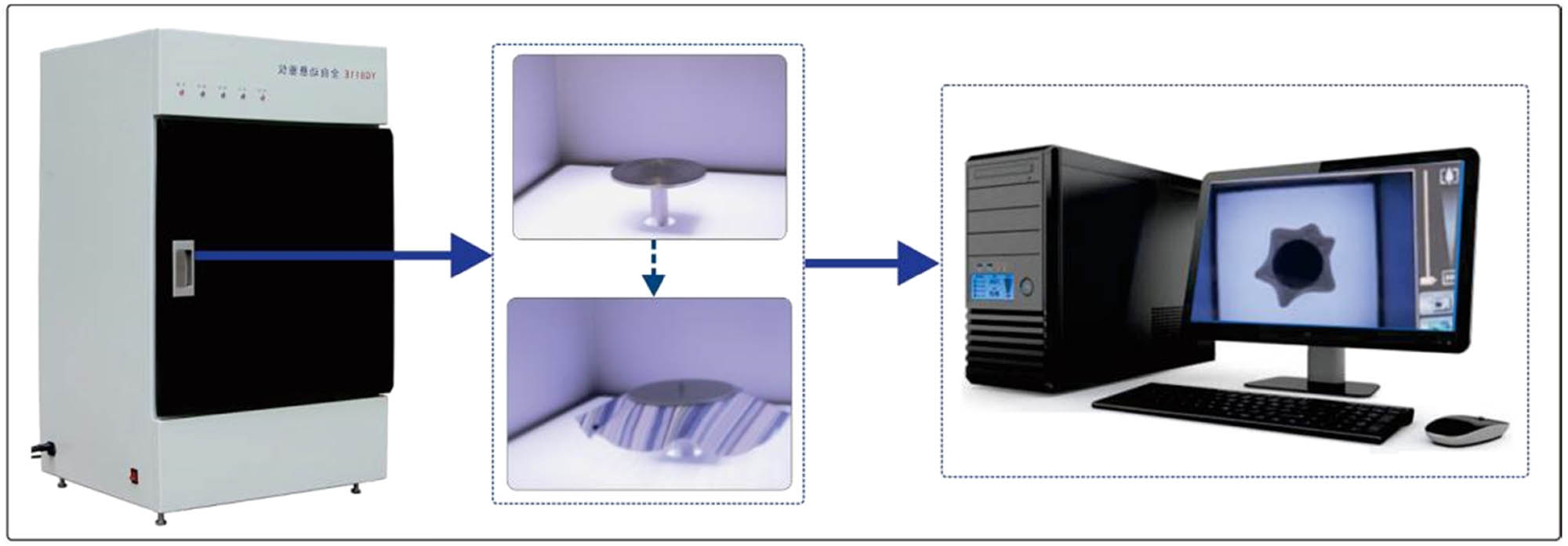
Traditional drape test.
Many scholars have tested and simulated the drape of woven fabrics. Sheng and Qi [3] used fabric structure and mechanical performance parameters to predict fabric drape morphology and simulated and reconstructed fabric drape morphology using fabric drape performance indicators. Feng et al. [4] experimentally measured the drape coefficient of real fabrics and used statistical analysis methods such as mean comparison, correlation analysis, and multiple regression analysis to create a regression model based on the drape coefficient of 3D virtual fabrics. They found that the physical parameters of the virtual fabric, such as bending strength and fabric density, have the greatest impact on the fabric drape. Du and Zhang [5] used Autodesk Maya to conduct drape testing on virtual fabrics and screened six indicators that have a significant impact on drape. Through regression analysis, they obtained the regression equation between the virtual fabric drape and six indicators and the influence of the main indicators on the virtual fabric drape coefficient. Hussain et al. [6] installed multiple depth cameras to reconstruct a 3D drape model and used the 3D drape model to predict the fabric feel. The objective ranking of fabrics obtained based on principal component analysis (PCA) of drape indicators was compared with the subjective ranking of fabric feel, verifying that fabric drape can be used as an objective alternative to fabric feel. Ju and Choi [7] introduced a neural network-based learning approach to derive cloth simulation parameters from the target fabric’s static drape shape. To illustrate the practicality of this approach, the estimated parameters from the trained neural network were applied to replicate the fabric’s draped appearance. Kim et al. [8] used a variety of fabrics through cluster analysis to create a system that divides fabrics into eight groups according to drape and establishes a model. Users can predict their groups based on the mechanical properties of the fabric. Kim and Lee [9] examined 30 silk fabrics commonly used in traditional Korean clothing, Hanbok, to compare the physical characteristics of natural versus virtual fabrics. They measured the KES-FB properties, CLO fabric properties, and drape of the silk fabrics. Then, they conducted a correlation analysis to explore how the physical properties of both natural and virtual fabrics impact draping behavior. Shin and Yun [10] analyzed fabric drape characteristics by dividing the fabric into one, two, and three dimensions to obtain detailed drape shape information, enhancing the accuracy of measurements for fabrics with diverse properties. Following a correlation analysis, each dimensional factor for evaluating drape was compared to conventional drape coefficients. Buyukaslan et al. [11] selected five fabric types to compare the drape of real and virtual fabrics across three factors: drape area, node count, and pleat shape. Kenkare et al. [12] put a skirt on a human body model for scanning, calculated the sag of the scanned image through image processing, and simulated it using 3D virtual clothing-making software. The similarity of real and virtual skirt pleats is evaluated by comparing the skirt volume and the number of nodes at the skirt’s lower edge. However, these approaches mainly address woven fabrics, leaving a gap in effective drape testing methods for fully formed knitted fabrics, which exhibit distinct 3D structures and performance characteristics.
3D printing technology has opened new opportunities for innovation in the textile industry, impacting not only materials but also design and manufacturing processes [13]. More and more fashion designers are using 3D printing technology to express their ideas and complete their designs, such as printing human models, fashionable clothes, and smart clothing. Sun and Valtas [14] examined the potential of incorporating 3D-printed partial garment components into commercial clothing production. They analyzed the cost and time of producing 3D-printed parts at the sample stage and presented an example of garment construction techniques. Their process and analysis showed the feasibility of specific 3D-printed garments. Sun and Zhao [15] conducted a comprehensive literature review, identifying key themes to develop a conceptual model illustrating connections among factors impacting 3D printing integration and examining potential impacts and challenges in the fashion industry. Wu et al. [16] reviewed advancements in 3D printing for traditional and intelligent clothing, emphasizing two well-established 3D printing technologies widely applied in fashion, and discussed the challenges and future outlook for 3D printing in intelligent apparel. They concluded by predicting that new material innovations will open further opportunities for developing 3D-printed clothing.
Spahiu et al. [17] employed a 3D printer to produce a model based on a scanned individual, enabling a comprehensive evaluation of clothing fit across various formats, including virtual body models and precise physical replicas. The study compared garment fit among actual garments, virtual models, and scaled 3D-printed versions, thereby validating the utility of 3D printing technology within the apparel industry. Subsequent research by Spahiu et al. [18,19] further explored the application of 3D printing technology in fashion design by creating skirts with diverse geometric structures and conducting an online survey to gauge consumer acceptance of 3D-printed clothing. The results indicated a favorable reception, with most respondents expressing a willingness to wear garments produced through 3D printing. Oh and Suh [20] illustrated the practicality of using scan data for mass customization, creating customized 3D-printed human models for garment fitting.
To address the limitations of existing drape testing methods, this study proposes a new 3D drape testing approach specifically designed for fully formed knitted garments, leveraging 3D-printed human body models in various postures. This method is intended to provide a more accurate reflection of the drape behavior and structure of fully formed knitted fabrics, ultimately aiding designers and manufacturers in developing high-quality, structurally complex garments.
2 Description of the proposed approach
This article combines the feasibility of 3D-printed human body models with the characteristics of fully formed knitted fabrics to create 3D knitted fabrics. It proposes a drape testing method for fully formed 3D knitted fabrics based on 3D printing human posture. Figure 2 shows the pipeline of testing the fully formed 3D knitted fabric drape. The pipeline has the following three parts: the physical module, the basic module, and the implementation module. The physical module is the preliminary preparation stage for the drape test, which mainly has two parts: one part is to establish the drape test base, that is, according to the standard human body size table, create human body models in different postures by 3ds-Max, and transfer the human body model files to a 3D printer for the final printing. The other part is the knitted drape test sample. The style and craftsmanship of the knitted sample are designed according to the style requirements, and the four-needle bed computerized flat knitting machine is used to knit the sample. The basic modules are a test base for the 3D-printed human body model and a fully formed knitted flared skirt sample knitted on a four-needle bed computerized flat knitting machine. It is worth noting that the sample size must match the mannequin’s specifications. For example, the standard mannequin corresponds to the standard flared skirt size, not the size for thin or fat body types. The implementation module includes four parts. The first is to match the test base and the test sample, that is, try on the matching knitted flared skirt on the human model test base; second, we place the human model wearing the knitted flared skirt on the debugged YG811 type drape style tester; third, we test the drape of the 3D fabric and obtain a variety of drape characterization indicators; finally, the SPSS software is used to analyze the drape characterization of the fully formed knitted flare skirt.
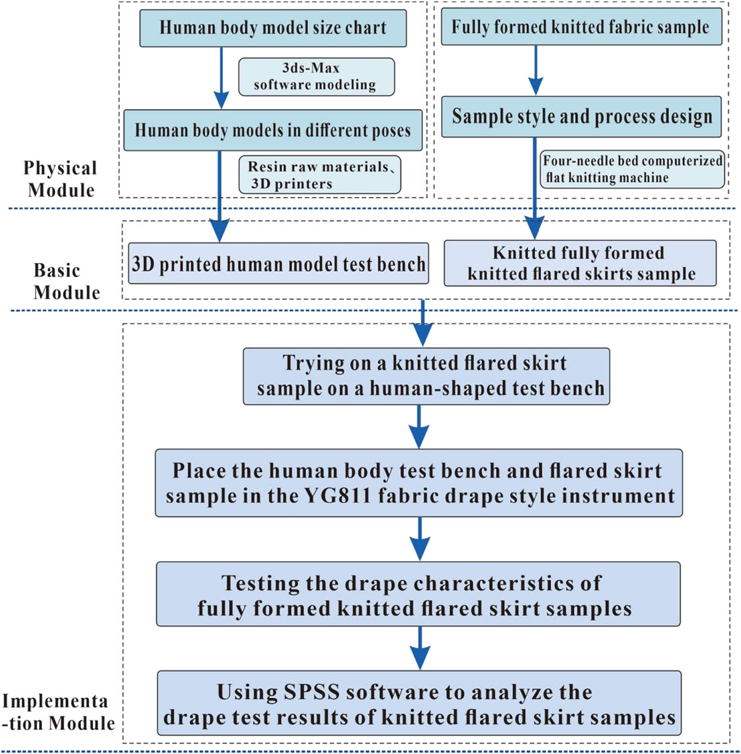
Technical roadmap for drape test of fully formed 3D knitted fabric.
2.1 3D printing human body models in different postures
According to the Chinese national standard GB/T 10000-2023, the standard human body model of 160/84A is used as the initial model. We used 3ds-Max software to build a standard human model that meets the requirements of 160 cm height and 84 cm chest circumference and optimizes the topological structure of the model to meet the needs of subsequent posture adjustment. After modeling, the model is exported to STL format to ensure its broad compatibility. In terms of posture set, the standing posture is achieved by naturally aligning the limbs and joints, and the skeleton binding of the walking posture is performed using inverse kinematics to achieve the natural joint movement of the upper and lower limbs. These postures are configured through a standardized skeleton system to ensure the repeatability and consistency of the postures in subsequent applications. We create a 3D human body model in 3ds-Max and select two common human postures that significantly impact the drape of lower body clothing to build the model, namely normal standing posture and walking posture. Standing and walking are the most common and natural postures of the human body in daily life, which can more accurately simulate the actual use of clothing, thereby providing more reliable drape test results. We use 3ds-Max to scale down the human body model size by four times. Table 1 shows the standard human body size and the reduced human body model size. The specific reduced human body model is shown in Figure 3, where Figure 3(a) presents Posture 1 (standing posture) from different viewing angles and Figure 3(b) presents Posture 2 (walking posture) from various angles. The upper part of the body is cut off to facilitate the camera to capture the drape photo of the fully formed knitted fabric from above.
Actual standard human body and 3D human body model measurements
| Measurements | Actual standard human body | 3D human body model |
|---|---|---|
| Chest circumference | 84 | 21 |
| Shoulder circumference | 38 | 9.5 |
| Hip circumference | 88 | 22 |
| Waist circumference | 68 | 17 |
| Front waist length | 41 | 10.2 |
| Back waist length | 38 | 9.5 |
| Bust height | 24 | 6 |
| Distance between breasts | 18 | 4.5 |
Unit: cm.
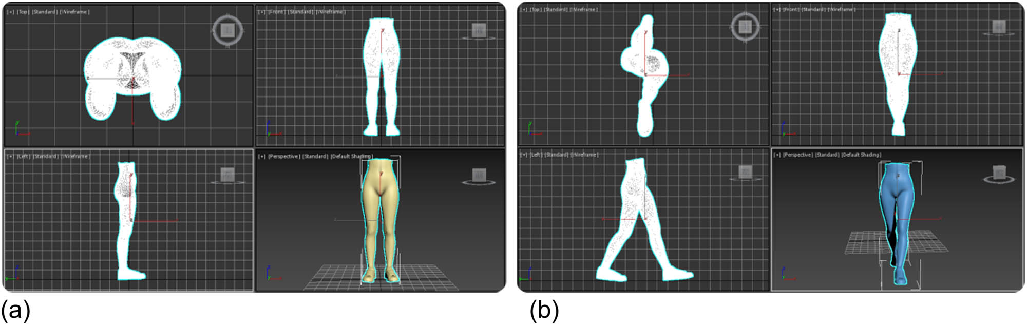
Human body modeling in different postures. (a) Pose 1. (b) Pose 2.
In this step, we output the human body model in STL format and use a 3D printer (iSLA1100 3D printer) to print the model. The 3D printer used in our experiments is shown in Figure 4(a). The printer uses a UV laser and a liquid UV-curing photopolymer (photosensitive resin) to print parts. The laser beam is controlled to scan the resin liquid surface so that the resin liquid surface solidifies to form a scanned cross-sectional film of the part. After curing one layer, the printer covers it with another layer of liquid resin and continues scanning to solidify this new layer and combine it with the cross-section of the previously cured part. This process repeats, growing layer by layer, thereby printing a 3D human body model. The printed human body model is shown in Figure 4(b) and (c).
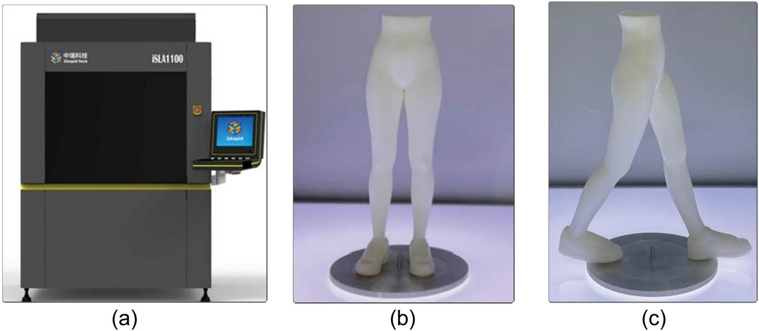
3D-printed human body model. (a) iSLA1100 3D printer, (b) pose 1 model, and (c) pose 2 model.
2.2 Fully formed knitted flared skirts design and knitting
2.2.1 Technological design
Due to its loose hem and larger fabric area, a skirt can intuitively express the drape of the fabric. The natural pleats and drape formed by a wide skirt under the influence of gravity can vividly show the fabric’s softness, stiffness, and drape effect and provide an ideal visual and tactile experience for evaluating the drape of the fabric. Therefore, we use knitted skirts in our drape test experiments. The knitted fully shaped flared skirt is designed according to the dimensions of the 3D human body model. Here, we use short and long multi-piece flared skirts. The flared skirt template is shown in Figure 5, where Figure 5(a) presents the front pattern and Figure 5(b) presents the back pattern. Both the front and back are four-piece flared skirts. The specific dimensions of the flared skirt are shown in Table 2. The sample template was drawn using Shima Seiki Apparel Design Software, and the four-needle bed MACH2XS-8-needle computerized flat knitting machine was used to knit the knitted flared skirt. The knitting raw materials used in this experiment: purple yarn is a blend of 32% cashmere and 68% cotton, 13/2 Nm yarn; green yarn is a blend of 22% cashmere and 78% cotton, 13/2 Nm of yarn.

Pattern figure. (a) Front pattern. (b) Back pattern.
Flared skirts’ size chart
| Style/category | Waist width | Waist height | Skirt length | Hem height | Hem width |
|---|---|---|---|---|---|
| Short flared skirt | 13 | 0.5 | 5.5 | 0.6 | 36 |
| Long flared skirt | 15 | 0.8 | 9.5 | 1.0 | 42 |
Unit: cm.
Before knitting a flared skirt on a four-needle bed computerized flat machine, it is necessary to obtain a yarn sample through yarn measurement. After washing and drying the yarn sample, the main structure of this type of fabric is obtained: the course density is four stitches/cm, and the wale density is five stitches/cm. Through actual knitting, the knitted structure of this sample was determined. As shown in Figure 5, the waist is a rib structure; the hem adopts a forward and reverse stitch structure that is not easy to curl; the main body part is a plain stitch structure/with different proportions of cable flowers. Process calculations are performed based on the flared skirt pattern, and then, the garment pattern is converted into a fully formed knitting process. The formula is as follows:
where U is the total number of technical needles in the vertical row; c is the width of the pattern, in centimeters; d h is the course density of the fabric, that is, the number of technical needles in the vertical row, in centimeters; V is the total number of technical stitches in the horizontal row; w is the height of the pattern, in centimeters; and d l is the wale density of the fabric, that is, the number of technical stitches in the horizontal row, in centimeters.
2.3 Forming principle of fully formed knitted fabrics
Fully formed knitted garments are knitted in a 3D form, where a complete knitted garment is knitted at one time on a computerized flat knitting machine [21,22]. It can be worn without stitching after getting off the machine, effectively reducing the need for cutting, sewing, etc., and thus saving costs and improving production efficiency.
Fully formed knitted garments are knitted as a whole piece on a computerized flat knitting machine, and some special knitting techniques are required during the knitting process to complete the entire knitting process [23]. For example, loop transfer technology transfers loops from one needle bed to another during the knitting process to achieve knitting with certain specific functions. Unlike the two-needle bed computerized flat knitting machine, which only has the following two parts: the front needle bed and the back needle bed. The front needle bed of the four-needle bed MACH2XS-8-needle computerized flat knitting machine includes the front upper needle bed (FU) and the front lower needle bed (FD). The back needle bed also includes the following two parts: the back upper needle bed (BU) and the back lower needle bed (BD). The upper needle bed of the front and back needle beds can be used to form reverse stitches or assist the lower needle bed in transferring stitches, etc. Therefore, the four-needle bed can efficiently knit more knitted fabrics of different styles and structures [24]. This knitting experiment uses a four-needle bed MACH2XS-8-needle computerized flat knitting machine to knit a flared skirt. The computerized flat knitting machine has a total of three knitting operating systems. S1 and S3 are transfer-specific systems, and S2 is a knitting-specific system; the system sequence used is different when the machine head runs from different directions.
The knitted flared skirt is knitted using a cylinder knitting method. Both the front and back pieces of the flared skirt are knitted with plain stitches on the lower needle bed and purl stitches on the upper needle bed. According to the design requirements of the knitted flared skirt, the necessary knitting structures include plain stitch, purl stitch, cable stitch, and rib stitch.
The positive and negative stitch structure refers to the structure of knitting one row/multiple rows of front knitting and one row/multiple rows of back knitting in the course direction [25]. When knitting the front and back knitting structures of the knitted flared skirt, the S2 knitting system is used. The lower needle bed of the system knits plain stitches, and the upper needle bed is used to knit purl stitches. This organization does not use a transfer stitch system. The specific knitting steps are shown in Figure 6. The first step is to knit the back body using the S2 knitting system to perform normal knitting on the back needle bed (BD); the second step is to knit the front body using the S2 knitting system on the front lower needle bed (FD) to perform normal knitting forward stitch; the third step is to knit the back body using the S2 knitting system to perform normal knitting back stitch on the back upper needle bed (BU); the fourth step is to knit the front body using the S2 knitting system to perform normal knitting and purl stitching on the front upper needle bed (FU); this process forms plain and purl stitches structure with one row of plain stitches and one row of purl stitches.

Plain and purl stitches knitting process.
2.3.1 Circular knitting-double layer plain stitch
The double-layer plain stitch is also called a cylindrical organizational structure, also known as a bag-shaped fabric [26]. The knitting process of the double-layer plain stitch is shown in Figure 7. The front loops of the single-sided plain stitch are knitted in turn along the front and back needle beds of the flat knitting machine to form a double-layer plain stitch structure. In this study, circular knitting was used to knit the experimental samples.

Double-layer plain stitch.
2.3.2 Cable stitch
The cable stitch is based on a plain stitch structure, forming a longitudinally twisted pattern on the front of the fabric by exchanging the positions of the loops from left to right or right to left. It can also be called “twisted rope” or “twisted” fabric [27]. This experiment uses 2 × 1 cable knitting as an example to illustrate the knitting steps. The specific procedure for knitting cable knitting on a computerized flat knitting machine is shown in Figure 8. The steps for knitting cables on the predecessor can be obtained through several steps as shown in Figure 8(a) of the predecessor knitting cable. In the first step, the S1 transfer system is used to transfer the front needle of the front body from the front lower needle bed (FD) to the back upper needle bed (BU); in the second step, the S2 knitting system is used to knit on the front lower needle bed (FD) and the back upper needle bed (BU); in the third step, the back needle bed (BU) shakes the bed two needle positions to the left; in the fourth step, the S3 transfer system is used to transfer a yarn loop of the front needle from the back upper needle bed (BU) to the front lower needle bed (FD); in the fifth step, the back needle bed shakes the bed three needles to the right position; in the sixth step, use the S3 transfer system to transfer the two yarn loops of the front stitch from the back upper needle bed (BU) to the front lower needle bed (FD). In the seventh step, the back needle bed shakes one needle position to the left, and the S2 knitting system in the back performs normal knitting on the lower and front upper needle beds, that is, complete the 2 × 1 cable knitting of the front body.
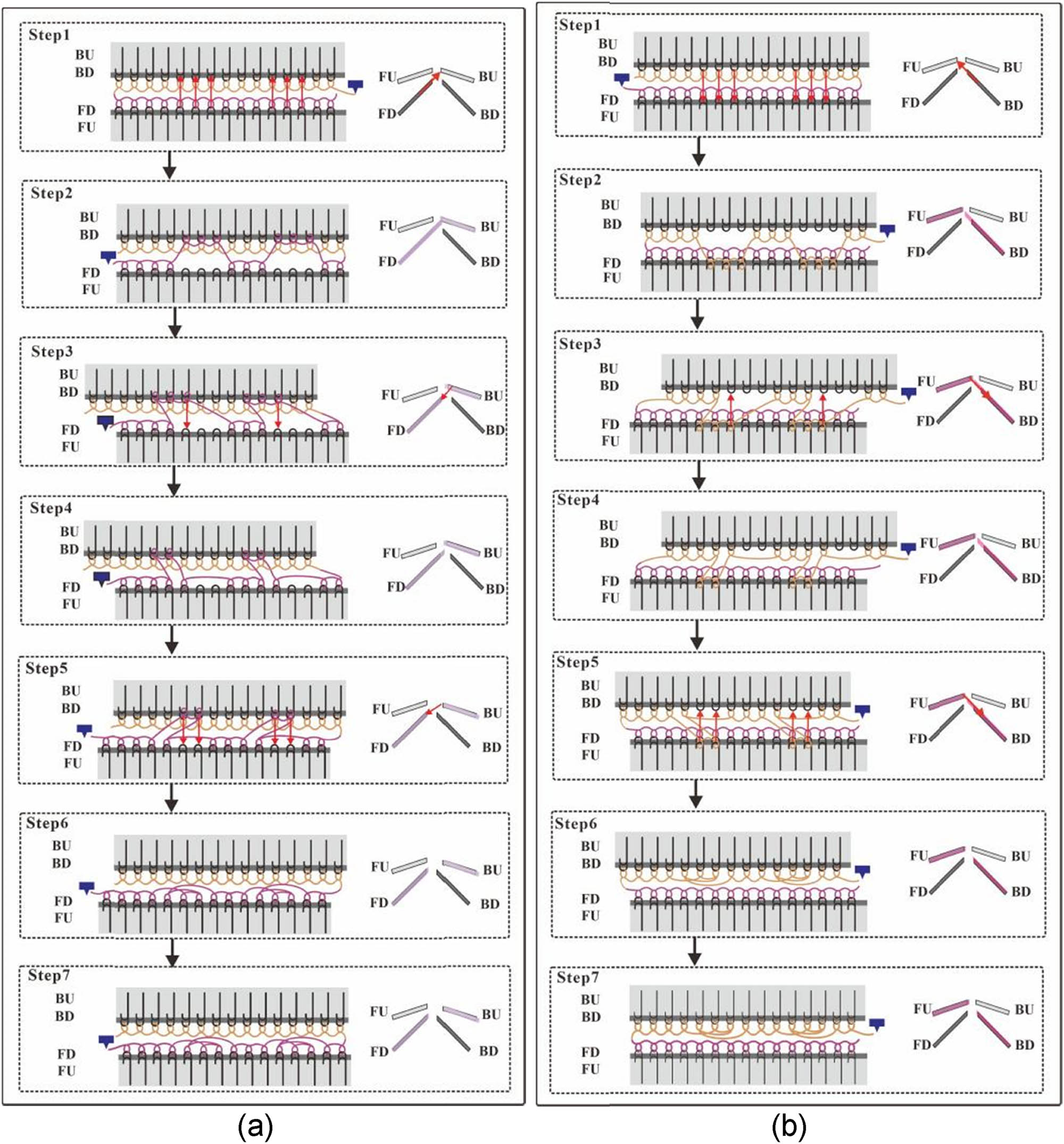
2 × 1 cable stitch knitting process. (a) Front body knitting steps. (b) Back body knitting steps.
From Figure 8(b) of the cable knitting on the back body, we can see the steps for knitting the cable knitting on the back body. The first step is to use the S1 transfer system to transfer the positive stitches of the back body from the back lower needle bed (BD) to the front upper needle bed (FU); in the second step, the S2 knitting system is used to knit on the back lower needle bed (BD) and the front upper needle bed (FU); the third step is to use the back needle bed to shake the two needle positions to the right; the fourth step is to use the S3 transfer system to transfer a yarn loop of the positive stitch from the front upper needle bed (FU) to the back lower needle bed (BD); the fifth step is to use the back needle bed to rock the three needle positions to the left; the sixth step is to use the S3 transfer system to transfer the two yarn loops of the positive stitch from the front upper needle bed (FU) to the back lower needle bed (BD); the seventh step is to use the back needle bed to move one needle position to the right, and the S2 knitting system performs normal knitting on the front lower needle bed (FD) and the back upper needle bed (BU), that is, the back body 2 × 1 cable knitting is completed.
2.3.3 Rib stitch
Rib stitch is the basic structure in double-sided knitted fabrics. It is composed of weft plain knitted front and back wales at certain intervals [28]. This experiment uses the 2 × 2 rib structure as an example to discuss the knitting process of the rib-knitted structure. The specific knitting steps are shown in Figure 9. It can be concluded from the front body knitting rib Figure 9(a) that when knitting the front body, the S1 transfer system is first used to transfer the purl stitch of the front body from the front lower needle bed (FD) to the back upper needle bed (BU); next, use the S2 knitting system to knit the loops on the front lower needle bed (FD) and the back upper needle bed (BU); again, use the S3 transfer system to transfer the purl-stitched yarn loop from the back upper needle bed (BU) to the front lower needle bed (FD) and finally use the S2 knitting system to knit the loops on the front lower needle bed (FD) and the back upper needle bed (BU) to complete this rib structure knitting. While the front body is being knitted, the back body is also being knitted. It can be seen from Figure 9(b) of knitting ribs on the back body that when knitting ribs on the back body, first use the S1 transfer system to transfer the purl stitches of the back body from the back lower needle bed (BD) to the front upper needle bed (FU); next, the S2 knitting system performs normal knitting on the back lower needle bed (BD) and the front upper needle bed (FU); the S3 transfer system is used again to transfer the purl yarn loop from the front upper needle bed (FU) to the back lower needle bed (BD); finally, use the S2 knitting system to knit normally on the back lower needle bed (BD) and the front upper needle bed (FU), that is, to complete the rib knitting of the back body of the knitted flared skirt.

Rib stitch knitting process. (a) Front body knitting steps. (b) Back body knitting steps.
Through the above various knitting procedures, a seamless fully formed flared skirt will be formed, which can be worn without stitching after taking off the machine. In Figure 10, different styles of seamless flared skirts and 3D flared skirts after trying on are shown.

Fully formed knitted flared skirts and flared skirts try on.
2.4 Drape test of fully formed knitted flared skirts
This experimental style uses four styles of flared skirts: short flat-knit flared skirts, short cable-knit flared skirts, long flat-knit flared skirts, and long cable-knit flared skirts. The raw materials are knitted with two different yarns. The two yarns used are a 32% cashmere and 68% cotton blend (13/2 Nm purple yarn) and a 22% cashmere and 78% cotton blend (13/2 Nm green yarn). In this experiment, a total of 18 knitted skirt samples were knitted for drape testing to verify the feasibility of the method.
The traditional drape test based on the umbrella projection method uses disks of different sizes as the base and evenly lays the fabric on the disk for drape testing [29]. The test object of this method is fabric and cannot be used for forming fabrics. Therefore, in this experiment, a fully formed knitted fabric drape test method based on the 3D human body shape was proposed based on the tubular shape of the fully formed knitted sample. Figure 11 shows the drape test steps of fully formed knitted fabrics. This method first uses the 3D-printed human body model as the test platform, then puts the fully formed knitted fabric on the human model, and finally, puts the model wearing the fully formed knitted skirt. Place it in the YG811 fabric drape tester and close the test door to perform the drape test.

Drape testing procedures for fully formed knitted flared skirts. (a) Pose 1-drape testing procedures. (b) Pose 2-drape testing procedures.
3 Results and discussion
Based on the 3D human body shape test method for the drape of fully formed knitted flared skirts, combined with the YG811 fabric drape style instrument to test the drape of fully formed knitted fabrics, ten indicators were obtained to characterize the drape characteristics, namely drape coefficient (C 1), drape degree (C 2), projected circumference (C 3), projected equivalent circle diameter (C 4), average difference in area between two fabric troughs (C 5), average difference in radius at fabric peak (C 6), drape curve shape coefficient (C 7), draping wave number (C 8), draping curve uniformity (C 9), and the average difference in the angle between the wave peak and the wave trough (C 10). Although these indicators fully reflect the drape characteristics of fabrics, there are different degrees of correlation between them, which makes direct analysis of all indicators time-consuming and may lead to duplicate information. Therefore, PCA is selected to simplify the analysis of indicator data. PCA is a commonly used data dimensionality reduction method that combines the original related indicators into a few principal components through linear transformation, retaining the original data information as much as possible while reducing redundant indicators. The specific experimental data of the drape test are shown in Table 3. After research, it was found that there is always a certain degree of correlation between these indicators. To select representative indicators and be able to use fewer indicators to comprehensively reflect the drape performance of the fabric [11,30], combined with the measured drape experimental data, the PCA method is used to find out the indicators with serious correlations in each indicator, to achieve the purpose of characterizing the drape performance of the fabric with a few indicators, thus greatly improving the experimental data analysis. Simplification provides convenience for subsequent fabric drape performance prediction and simulation verification and provides a certain theoretical basis for the establishment of a drape performance index system.
Flared skirts drape test data sheet
| Flared skirts code/index | C 1 | C 2 | C 3 | C 4 | C 5 | C 6 | C 7 | C 8 | C 9 | C 10 |
|---|---|---|---|---|---|---|---|---|---|---|
| 1 | 0.0237 | 0.9763 | 404.3900 | 128.7300 | 0.1045 | 0.0310 | 0.0050 | 4.0000 | 0.1152 | 0.0993 |
| 2 | 0.0448 | 0.9552 | 427.7400 | 136.1600 | 0.2359 | 0.0721 | 0.0068 | 6.0000 | 0.0945 | 0.0758 |
| 3 | 0.0095 | 0.9905 | 387.7700 | 123.4400 | 0.5134 | 0.1050 | 0.0047 | 4.0000 | 0.2045 | 0.1765 |
| 4 | 0.0262 | 0.9738 | 407.1700 | 129.6100 | 0.2697 | 0.0394 | 0.0050 | 6.0000 | 0.2102 | 0.1810 |
| 5 | 0.0270 | 0.9730 | 408.1500 | 129.9200 | 0.2031 | 0.0672 | 0.0054 | 4.0000 | 0.1141 | 0.0960 |
| 6 | 0.0297 | 0.9703 | 411.1800 | 130.8900 | 0.1959 | 0.0646 | 0.0049 | 4.0000 | 0.1487 | 0.1236 |
| 7 | 0.0344 | 0.9656 | 416.3800 | 132.5400 | 0.1518 | 0.0643 | 0.0050 | 4.0000 | 0.2038 | 0.1843 |
| 8 | 0.0215 | 0.9785 | 401.7900 | 127.9000 | 0.2433 | 0.0555 | 0.0051 | 6.0000 | 0.2065 | 0.1640 |
| 9 | 0.0156 | 0.9844 | 395.0400 | 125.7500 | 0.6091 | 0.1271 | 0.0045 | 4.0000 | 0.2446 | 0.2093 |
| 10 | 0.0130 | 0.9870 | 391.9600 | 124.7700 | 0.1344 | 0.0546 | 0.0033 | 3.0000 | 0.4656 | 0.4179 |
| 11 | 0.0091 | 0.9909 | 387.3600 | 123.3000 | 0.3875 | 0.0782 | 0.0062 | 4.0000 | 0.1941 | 0.1436 |
| 12 | 0.0232 | 0.9753 | 404.3600 | 128.4300 | 0.1005 | 0.0300 | 0.0056 | 4.0000 | 0.1122 | 0.0990 |
| 13 | 0.0438 | 0.9522 | 427.7200 | 136.2160 | 0.2369 | 0.0761 | 0.0062 | 6.0000 | 0.1045 | 0.0768 |
| 14 | 0.0093 | 0.9885 | 387.6700 | 123.2400 | 0.5114 | 0.1020 | 0.0043 | 4.0000 | 0.2040 | 0.1735 |
| 15 | 0.0260 | 0.9708 | 407.1500 | 129.5100 | 0.2637 | 0.0364 | 0.0050 | 6.0000 | 0.2082 | 0.1800 |
| 16 | 0.0268 | 0.9710 | 408.1200 | 129.8200 | 0.2011 | 0.0662 | 0.0056 | 4.0000 | 0.1121 | 0.0980 |
| 17 | 0.0298 | 0.9763 | 411.2800 | 130.8600 | 0.1969 | 0.0626 | 0.0051 | 4.0000 | 0.1477 | 0.1226 |
| 18 | 0.0364 | 0.9646 | 416.2800 | 132.5100 | 0.1528 | 0.0623 | 0.0053 | 4.0000 | 0.2028 | 0.1833 |
Use SPSS26.0 software to extract drape characterization indicators – PCA. For PCA, the higher the correlation between variables, the more suitable it is for principal component extraction. The information obtained through analysis using SPSS26.0 software includes a variable correlation matrix table, total variance explanation table, component matrix table, and component score coefficient matrix table.
The variable correlation matrix is shown in Table 4. For example, the correlation coefficients between the drape coefficient (C 1) and drape degree (C 2), projected circumference (C 3) and projected equivalent circle diameter (C 4) are 0.982, 0.999, and 0.999 respectively, indicating that the C 1 is closely related to the C 2, C 3, and C 4. The correlation coefficient between C 5 and C 6 is 0.848, indicating that there is a significant correlation; the correlation coefficients between multiple variables in the table are large, indicating that there is a correlation between these variables. The significant correlation indicates the need for PCA.
Variable correlation matrix table
| Drape index | C 1 | C 2 | C 3 | C 4 | C 5 | C 6 | C 7 | C 8 | C 9 | C 10 | |
|---|---|---|---|---|---|---|---|---|---|---|---|
| Correlation | C 1 | 1.000 | −0.982 | 0.999 | 0.999 | −0.553 | −0.313 | 0.581 | 0.476 | −0.510 | −0.477 |
| C 2 | −0.982 | 1.000 | −0.984 | −0.983 | −0.521 | −0.308 | −0.594 | −0.528 | 0.515 | 0.484 | |
| C 3 | 0.999 | −0.984 | 1.000 | 1.000 | −0.557 | −0.323 | 0.584 | 0.487 | −0.522 | −0.490 | |
| C 4 | 0.999 | −0.983 | 1.000 | 1.000 | −0.553 | −0.317 | 0.582 | 0.488 | −0.517 | −0.485 | |
| C 5 | −0.553 | 0.521 | −0.557 | −0.553 | 1.000 | 0.848 | −0.166 | 0.003 | 0.150 | 0.105 | |
| C 6 | −0.313 | 0.308 | −0.323 | −0.317 | 0.848 | 1.000 | −0.102 | −0.216 | 0.111 | 0.081 | |
| C 7 | 0.581 | −0.594 | 0.584 | 0.582 | −0.166 | −0.102 | 1.000 | 0.490 | −0.777 | −0.801 | |
| C 8 | 0.476 | −0.528 | 0.487 | 0.488 | 0.003 | −0.216 | 0.490 | 1.000 | −0.326 | −0.356 | |
| C 9 | −0.510 | 0.515 | −0.522 | −0.517 | 0.150 | 0.111 | −0.777 | −0.326 | 1.000 | 0.995 | |
| C 10 | −0.477 | 0.484 | −0.490 | −0.485 | 0.105 | 0.081 | −0.801 | −0.356 | 0.995 | 1.000 | |
Table 5 provides the total variance explained by each common factor and the cumulative variance. According to the principle of determining the main component based on the component with an eigenvalue greater than 1, the first three factors in Table 5 have an eigenvalue greater than 1, so the first three components are selected as the main components, and the sum of the eigenvalues of the first three factors is 89.457%, that is, it can explain most of the information of the original ten variables, so it is appropriate to extract three common factors. PCA can reduce the complexity of the original data to a considerable extent.
Total variance explanation table
| Drape index | Initial eigenvalue | Extract the sum of squared loads | Rotating load sum of squares | ||||||
|---|---|---|---|---|---|---|---|---|---|
| Total | Variance (%) | Accumulation (%) | Total | Variance (%) | Accumulation (%) | Total | Variance (%) | Accumulation (%) | |
| C 1 | 5.940 | 59.400 | 59.400 | 5.940 | 59.400 | 59.400 | 4.100 | 41.003 | 41.003 |
| C 2 | 1.930 | 19.300 | 78.700 | 1.930 | 19.300 | 78.700 | 2.792 | 27.917 | 68.919 |
| C 3 | 1.076 | 10.758 | 89.457 | 1.076 | 10.758 | 89.457 | 2.054 | 20.538 | 89.457 |
| C 4 | 0.762 | 7.616 | 97.073 | ||||||
| C 5 | 0.241 | 2.410 | 99.482 | ||||||
| C 6 | 0.027 | 0.269 | 99.752 | ||||||
| C 7 | 0.022 | 0.218 | 99.970 | ||||||
| C 8 | 0.002 | 0.019 | 99.988 | ||||||
| C 9 | 0.001 | 0.011 | 99.999 | ||||||
| C 10 | 0.000 | 0.001 | 100.000 | ||||||
Extraction method: PCA.
It can be seen from Table 6 of the initial component matrix that the typical representative variables of each main factor in the initial component matrix are not very prominent, which easily makes the meaning of the components ambiguous and is inconvenient for analyzing practical problems. Therefore, the initial factor component matrix needs to be Kaiser’s standardized orthogonal rotation method (i.e., maximum variance rotation method), which is used for rotation. The rotated component matrix is shown in Table 7. From the rotated component matrix Table 7, it can be concluded that the first principal component is closely related to the drape coefficient (C 1) and drape degree (C 2), projected circumference (C 3), projected equivalent circle diameter (C 4), and drape wave number (C 8). The first principal component (F 1) can be interpreted as the fabric Drape form factor. The second principal component is closely related to the drape curve shape coefficient (C 7), draping curve uniformity (C 9), and the average difference in the angle between the wave peak and the wave trough (C 10). The second principal component (F 2) can be interpreted as the fabric drape surface shape factor; the third principal component is closely related to the average difference in area between two fabric troughs (C 5) and average difference in radius at fabric peak (C 6). The third principal component (F 3) can be interpreted as the fabric drape uniformity factor.
Initial component matrix table
| Drape index | C 1 | C 2 | C 3 | C 4 | C 5 | C 6 | C 7 | C 8 | C 9 | C 10 | |
|---|---|---|---|---|---|---|---|---|---|---|---|
| Component | F 1 | 0.943 | −0.943 | 0.949 | 0.947 | −0.549 | −0.404 | 0.757 | 0.569 | −0.718 | −0.697 |
| F 2 | −0.161 | 0.133 | −0.157 | −0.156 | 0.728 | 0.663 | 0.459 | 0.179 | −0.536 | −0.582 | |
| F 3 | 0.244 | −0.26 | 0.232 | 0.241 | 0.377 | 0.509 | −0.17 | 0.309 | 0.397 | 0.392 | |
Extraction method: PCA.
Rotated component matrix table
| Drape index | C 1 | C 2 | C 3 | C 4 | C 5 | C 6 | C 7 | C 8 | C 9 | C 10 | |
|---|---|---|---|---|---|---|---|---|---|---|---|
| Component | F 1 | 0.911 | −0.916 | 0.908 | 0.911 | −0.305 | −0.102 | 0.43 | 0.609 | −0.252 | −0.233 |
| F 2 | −0.259 | 0.268 | −0.271 | −0.265 | 0.009 | 0.047 | −0.793 | −0.252 | 0.944 | 0.961 | |
| F 3 | −0.28 | 0.25 | −0.287 | −0.28 | 0.938 | 0.921 | −0.008 | 0.13 | 0.073 | 0.029 | |
Rotation method: Kaiser normalization varimax method.
Component score coefficient matrix (Table 8) gives detailed information on the component score coefficient matrix, based on which the expression of each principal component can be directly written. Each variable in the expression is no longer a primitive variable but a standardized variable. The first principal component (F 1) expression formula (3) is obtained from the component score coefficient matrix table in Table 8. Among them, the coefficient values of indicators C 1, C 2, C 3, C 4, and C 8 are larger, and they score higher on the F 1 principal component, indicating that there is a close relationship between these five indicators and the F 1 principal component. The second principal component (F 2) expression formula (4) is obtained from the component score coefficient matrix table in Table 8. The expression formula of the second principal component (F 2) is as follows (4), among which the coefficient values of indicators C 7, C 9, and C 10 are larger, and they score higher on the F 2 principal component, indicating that the relationship between these three indicators and the F 2 principal component is close relationship; The third principal component (F 3) expression formula (5) is obtained from the component score coefficient matrix table in Table 8. the expression formula of the third principal component is as follows (5), in which the coefficient values of indicators C 5 and C 6 are larger and score higher on the F 3 principal component, indicating that these two indicators are closely related to the F 3 principal component.
Components score coefficient matrix table
| Drape index | Component | ||
|---|---|---|---|
| F 1 | F 2 | F 3 | |
| C 1 | 0.273 | 0.093 | 0.021 |
| C 2 | −0.280 | −0.092 | −0.041 |
| C 3 | 0.267 | 0.085 | 0.016 |
| C 4 | 0.271 | 0.090 | 0.021 |
| C 5 | 0.087 | −0.013 | 0.516 |
| C 6 | 0.184 | 0.062 | 0.555 |
| C 7 | −0.028 | −0.309 | 0.040 |
| C 8 | 0.236 | 0.042 | 0.207 |
| C 9 | 0.165 | 0.445 | 0.053 |
| C 10 | 0.168 | 0.456 | 0.031 |
Extraction method: PCA; rotation method: Kaiser normalization varimax method.
Taking 18 pieces of fully formed knitted flared skirts and 3D-printed human postures tested the drape test method. Based on the PCA method, the drape of the fully formed knitted flared skirt under 3D human body morphology was tested and analyzed. Three principal components, namely the drape shape factor (F 1), the surface morphology factor (F 2), and the uniformity factor (F 3), were extracted from ten drape characteristics, and the physical meaning of each factor was reasonably explained. This extraction process simplifies the analysis of drape characteristics and provides a scientific basis for constructing an efficient fabric drape performance index system. By conducting experiments and evaluating the drape performance of fabrics on a 3D-printed human body model, this study can more realistically reflect the drape form of fabrics in actual wearing situations compared to the traditional two-dimensional (2D) plane test method, thereby significantly improving the practicality and effectiveness of the test. The rotated component matrix analysis and component score coefficient matrix table show that the proposed factor partitioning model not only reduces the complexity of drape analysis but is also more suitable for drape performance evaluation under multiple postures, further verifying the effectiveness of the PCA method based on the 3D human body model. Unlike the existing research results based on 2D planes, this study proposed vital indicators that can effectively reflect the drape performance of fabrics through 3D model drape tests. This innovative method provides a new direction for evaluating textile drapes and lays the foundation for predicting fabric performance in subsequent simulations.
4 Conclusions
This article presents an innovative method for assessing the drape properties of fully formed knitted fabrics, leveraging a 3D human body model under gravitational influence to objectively evaluate drape performance in a wearing state. A specifically designed knitted flared skirt was created to fit a 3D-printed human model using a computerized four-needle bed flat knitting machine. Using the YG811 fabric drape test instrument and statistical analysis of ten key drape indicators in SPSS26.0, we obtained comprehensive insights into the drape characteristics of the fully formed fabric.
The findings demonstrate that a 3D-printed human model as a testing platform, dressed in a fully formed knitted flared skirt, accurately replicates real-world fabric drape on the human form. This approach provides designers with a robust tool to interpret and refine garment silhouette and functional aspects, enhancing fabric and garment development processes. The developed method offers significant potential for textile and fashion industries, where precise drape testing is vital in garment fit, aesthetic, and comfort evaluation. Future research should investigate dynamic drape assessments that simulate movement, apply this approach to varied knitted fabric structures, and explore more complex garment types. Furthermore, integrating this method with digital twin technology or virtual prototyping systems may accelerate the design and evaluation stages, allowing more accurate predictions of garment behavior and aesthetics across diverse body shapes.
-
Funding information: This work was supported by the State Scholarship Fund from China Scholarship Council (No. 202306790021); Inner Mongolia Autonomous Region Science and Technology Plan Project (No. 2023YFKL0001); and the Postgraduate Research & Practice Innovation Program of Jiangsu Province grant funded by the Jiangsu Province government (No. KYCX23_2477).
-
Author contributions: Bilian Cheng developed the research idea and drafted the first manuscript. Gaoming Jiang guided the design and process research of knitted garments. Fanglue Zhang reviewed the first draft and guided to improve the overall framework of the article. Ailan Wan and Haisang Liu provided many suggestions for data analysis. Bingxian Li and Lizhong Gao provided many suggestions for 3D-printed human body models.
-
Conflict of interest: Authors state no conflict of interest.
-
Ethical approval: The conducted research is not related to either human or animal use.
-
Data availability statement: The datasets generated during and/or analyzed during the current study are available from the corresponding author on reasonable request.
References
[1] Lu, L., Jiang, G., Wu, G. (2022). The knitting methods for seamless garments based on four-needle bed computerized flat machine. Textile Research Journal, 92(3–4), 479–497. 10.1177/004051752110351.Search in Google Scholar
[2] Wei, Q., Zhang, D. (2023). A textile architecture-based discrete modeling approach to simulating fabric draping processes. Journal of Industrial Textiles, 53, 1–23. 10.1177/15280837231159678.Search in Google Scholar
[3] Sheng, Y., Qi, H. Q. (2010). Simulation of fabric draping shape. Journal of Textile Research, 31(10), 34–39. 10.13475/j.fzxb.2010.10.009.Search in Google Scholar
[4] Feng, H. F., Liu, C., Wang, G. Q., Zhang, J. L. (2022). Research on the drape of fabric in 3D simulation. Wool Textile Journal, 50(5),104–109. 10.19333/j.mfkj.20211102506.Search in Google Scholar
[5] Du, Y. X., Zhang, H. (2016). Analysis of the influencing factors of virtual textile drape property based on autodesk maya. Progress in Textile Science and Technology, 10, 11–14. 10.19507/j.cnki.1673-0356.2016.10.004.Search in Google Scholar
[6] Hussain, A., Zhong, Y., Naveed, T., Yu, Z., Xi, Z., Ge, W. (2020). A new approach to evaluate fabric hand based on three-dimensional drape model. Autex Research Journal, 20(2),155–167. 10.2478/aut-2019-0011.Search in Google Scholar
[7] Ju, E., Choi, M. G. (2020). Estimating cloth simulation parameters from a static drape using neural networks. IEEE Access, 8, 195113–195121. 10.1109/ACCESS.2020.3033765.Search in Google Scholar
[8] Kim, J., Kim, Y. J., Shim, M., Jun, Y., Yun, C. (2020). Prediction and categorization of fabric drapability for 3D garment virtualization. International Journal of Clothing Science and Technology, 32(4), 523–535. 10.1108/IJCST-08-2019-0126.Search in Google Scholar
[9] Kim, J. H., Lee, J. S. (2024). Investigating parameters affecting the real and virtual drapability of silk fabrics for traditional hanbok. Fashion and Textiles, 11(1), 21. 10.1186/s40691-024-00388-6.Search in Google Scholar
[10] Shin, B., Yun, C. (2023). Multidimensional analysis for fabric drapability. Fashion and Textiles, 10(33), 1–16. 10.1186/s40691-023-00352-w.Search in Google Scholar
[11] Buyukaslan, E., Jevsnik, S., Kalaoglu, F. (2018). Comparative analysis of drape characteristics of actually and virtually draped fabrics. International Journal of Clothing Science and Technology, 30(3), 286–301. 10.1108/IJCST-06-2017-0085.Search in Google Scholar
[12] Kenkare, N., Lamar, T. A., Pandurangan, P., Eischen, J. (2008). Enhancing accuracy of drape simulation. Part I: Investigation of drape variability via 3D scanning. Journal of the Textile Institute, 99(3), 211–218. 10.1080/00405000701489222.Search in Google Scholar
[13] Xiao, Y. Q., Kan, C. W. (2022). Review on development and application of 3D-printing technology in textile and fashion design. Coatings, 12(2), 267. 10.3390/coatings12020267.Search in Google Scholar
[14] Sun, D., Valtas, A. (2016). 3D printing for garments production: An exploratory study. Journal of Fashion Technology and Textile Engineering, 4(3), 1000139, 10.4172/2329-9568.1000139.Search in Google Scholar
[15] Sun, L., Zhao, L. (2017). Envisioning the era of 3D printing: a conceptual model for the fashion industry. Fashion and Textiles, 4, 1–16. 10.1186/s40691-017-0110-4.Search in Google Scholar
[16] Wu, S., Zeng, T., Liu, Z., Ma, G., Xiong, Z., Zuo, L., et al. (2022). 3D printing technology for smart clothing: A topic review. Materials, 15(20), 7391. 10.3390/ma15207391.Search in Google Scholar PubMed PubMed Central
[17] Spahiu, T., Grimmelsmann, N., Ehrmann, A., Shehi, E., Piperi, E. (2016, November). On the possible use of 3D printing for clothing and shoe manufacture. In Proceedings of the 7th International Conference of Textile, Tirana, Albania, pp. 10–11.Search in Google Scholar
[18] Spahiu, T., Canaj, E., Shehi, E. (2020). 3D printing for clothing production. Journal of Engineered Fibers and Fabrics, 15, 1–8, 10.1177/1558925020948216.Search in Google Scholar
[19] Spahiu, T., Zlatev, Z., Ibrahimaj, E., Ilieva, J., Shehi, E. (2022). Drape of composite structures made of textile and 3D printed geometries. Machines, 10(7), 587. 10.3390/machines10070587.Search in Google Scholar
[20] Oh, S., Suh, D. (2021). Mannequin fabrication methodology using 3D-scanning, modeling and printing. International Journal of Clothing Science and Technology, 33(5), 683–695. org/10.1108/IJCST-05-2020-0076.Search in Google Scholar
[21] Underwood, J. (2009). The design of 3D shape knitted preforms. (Doctoral dissertation). RMIT University, Melbourne.Search in Google Scholar
[22] Wang, J., Shen, D., Yao, X., Lu, W. (2022). Establishment and application of whole garment knitted skirt template library combining design and technology. International Journal of Clothing Science and Technology, 34(5), 745–763. 10.1108/IJCST-02-2021-0014.Search in Google Scholar
[23] Peng, J., Jiang, G., Cong, H., Luo, X., Zhao, Y. (2018). Development of whole garment formed on four-bed computerized flat knitting machine. International Journal of Clothing Science and Technology, 30(3), 320–331. 10.1108/IJCST-07-2017-0105.Search in Google Scholar
[24] Shimaseiki. (2024). Shima seiki manufacturing. Available at: https://www.shimaseiki.com.cn/industrial_solutions/machines/.Search in Google Scholar
[25] Li, T., Mao, L. L., Li, N. (2020). Application of positive and negative stitches in the creative design of sweater pattern. Journal of Xi’an Polytechnic University, 34(6), 14–19. 10.13338/j.issn.1674-649x.2020.06.003.Search in Google Scholar
[26] Zhan, B. Q., Li, Y. X., Dong, Z. J., Cong, H. L. (2022). Research on virtual display of fully-formed double-layer knitted clothing parts. Journal of Textile Research, 43(8), 147–152. 10.13475/j.fzxb.20210802506.Search in Google Scholar
[27] Sha, S., Luo, L., Deng, Z., Yuan, D., Li, B., Jiang, X., et al. (2018). 3-D deformation behavior simulation of cable stitch based on particle system in weft knitted fabrics. Fibers and Polymers, 19(9), 1997–2006. 10.1007/s12221-018-8101-7.Search in Google Scholar
[28] Huang, H. (2005). The decoration of rib-knit in the knitted wear. Journal of Zhejiang Science and Technology University, 2,134–138.Search in Google Scholar
[29] Balci Kilic, G., Demir, M., Kilic, M. (2021). Dynamic drape behaviours of wool woven suiting fabrics considering real-time use. International Journal of Clothing Science and Technology, 33(5), 811–823. 10.1108/IJCST-11-2020-0173.Search in Google Scholar
[30] Han, Y. X. (2017). Based on the CLO3D fabric drape simulation studies. (MA thesis). Beijing Institute of Fashion Technology, Beijing. 10.26932/d.cnki.gbjfc.2017.000001.Search in Google Scholar
© 2024 the author(s), published by De Gruyter
This work is licensed under the Creative Commons Attribution 4.0 International License.
Articles in the same Issue
- Characterization of viscoelastic properties of yarn materials: Dynamic mechanical analysis in the transversal direction
- Analysis of omni-channel implementations that are preferred by consumers in clothing sector
- Structural modeling and analysis of three-dimensional cross-linked braided preforms
- An experimental study of mechanical properties and comfortability of knitted imitation woven shirt fabrics
- Technology integration to promote circular economy transformation of the garment industry: a systematic literature review
- Research on T-shirt-style design based on Kansei image using back-propagation neural networks
- Research on She nationality clothing recognition based on color feature fusion with PSO-SVM
- Accuracy prediction of wearable flexible smart gloves
- Preparation and performance of stainless steel fiber/Lyocell fiber-blended weft-knitted fabric
- Development of an emotional response model for hospital gown design using structural equation modeling
- Preparation and properties of stainless steel filament/pure cotton woven fabric
- Facemask comfort enhancement with graphene oxide from recovered carbon waste tyres
- Use of enzymatic processes in the tanning of leather materials
- Optical-related properties and characterization of some textile fibers using near-infrared spectroscopy
- Network modeling of aesthetic effect for Chinese Yue Opera costume simulation images
- Predicting consumers’ garment fit satisfactions by using machine learning
- Non-destructive identification of wool and cashmere fibers based on improved LDA using NIR spectroscopy
- Study on the relationship between structure and moisturizing performance of seamless knitted fabrics of protein fibers for autumn and winter
- Antibacterial and yellowing performances of sports underwear fabric with polyamide/silver ion polyurethane filaments
- Numerical and experimental analysis of ballistic performance in hybrid soft armours composed of para-aramid triaxial and biaxial woven fabrics
- Phonetic smart clothing design based on gender awareness education for preschoolers
- Determination of anthropometric measurements and their application in the development of clothing sizing systems for women in the regions of the Republic of Croatia
- Research on optimal design of pleated cheongsam based on Kano–HOQ–Pugh model
- Numerical investigation of weaving machine heald shaft new design using composite material to improve its performance
- Corrigendum to “Use of enzymatic processes in the tanning of leather materials”
- Shaping of thermal protective properties of basalt fabric-based composites by direct surface modification using magnetron sputtering technique
- Numerical modeling of the heat flow component of the composite developed on the basis of basalt fabric
- Weft insertion guideway design based on high-temperature superconducting levitation
- Ultrasonic-assisted alkali hydrolysis of polyethylene terephthalate fabric and its effect on the microstructure and dyeing properties of fibers
- Comparative study on physical properties of bio-based PA56 fibers and wearability of their fabrics
- Investigation of the bias tape roll change time efficiency in garment factories
- Analysis of foot 3D scans of boys from Polish population
- Optimization of garment sewing operation standard minute value prediction using an IPSO-BP neural network
- Influence of repeated switching of current through contacts made of electroconductive fabrics on their resistance
- Numerical calculation of air permeability of warp-knitted jacquard spacer shoe-upper materials based on CFD
- Compact Spinning with Different Fibre Types: An Experimental Investigation on Yarn Properties in the Condensing Zone with 3D-Printed Guiding Device
- Modeling of virtual clothing and its contact with the human body
- Advances in personalized modelling and virtual display of ethnic clothing for intelligent customization
- Investigation of weave influence on flame retardancy of jute fabrics
- Balloonless spinning spindle head shape optimisation
- Research on 3D simulation design and dynamic virtual display of clothing flexible body
- Turkish textile and clothing SMEs: Importance of organizational learning, digitalization, and internationalization
- Corrigendum To: “Washing characterization of compression socks”
- Study on the promotion multiple of blood flow velocity on human epidermal microcirculation of volcanic rock polymer fiber seamless knitted fabric
- Bending properties and numerical analysis of nonorthogonal woven composites
- Bringing the queen mother of the west to life: Digital reconstruction and analysis of Taoist Celestial Beings Worshiping mural’s apparel
- Modeling process for full forming sports underwear
- Retraction of: Ionic crosslinking of cotton
- An observational study of female body shape characteristics in multiracial Malaysia
- Study on theoretical model and actual deformation of weft-knitted transfer loop based on particle constraint
- Design and 3D simulation of weft-knitted jacquard plush fabrics
- An overview of technological challenges in implementing the digital product passport in the textile and clothing industry
- Understanding and addressing the water footprint in the textile sector: A review
- Determinants of location changes in the clothing industry in Poland
- Influence of cam profile errors in a modulator on the dynamic response of the heald frame
- Quantitative analysis of wool and cashmere fiber mixtures using NIR spectroscopy
- 3D simulation of double-needle bar warp-knitted clustered pile fabrics on DFS
- Finite element analysis of heat transfer behavior in glass fiber/metal composite materials under constant heat load
- Price estimation and visual evaluation of actual white fabrics used for dress shirts and their photographic images
- Effect of gluing garment materials with adhesive inserts on their multidirectional drape and bending rigidity
- Optimization analysis of carrier-track collision in braiding process
- Numerical and experimental analysis of the ballistic performance of soft bulletproof vests for women
- The antimicrobial potential of plant-based natural dyes for textile dyeing: A systematic review using prisma
- Influence of sewing parameters on the skin–fabric friction
- Validation by experimental study the relationship between fabric tensile strength and weave structures
- Optimization of fabric’s tensile strength and bagging deformation using surface response and finite element in stenter machine
- Analysis of lean manufacturing waste in the process flow of ready-to-wear garment production in Nigeria
- An optimization study on the sol–gel process to obtain multifunctional denim fabrics
- Drape test of fully formed knitted flared skirts based on 3D-printed human body posture
- Supplier selection models using fuzzy hybrid methods in the clothing textile industry