
Optimized design of a semimetal gasket operating in flange-bolted joints
-
Przemysław Jaszak


Abstract
The paper presents a new design of semimetal gasket, which has been subjected to the optimization process. The main objective function was to achieve the maximum elastic recovery of the gasket at imposed functional and strength limitations. The objective function was described indirectly in the form of the required minimum angle of the gasket’s unload curve inclination, which was a measure of the average value of the elastic modulus at unloading. Strength limitations resulted from not exceeding the ultimate stress of the materials, while functional limitations imposed the achievement of proper contact pressure that ensures a given level of tightness class. The characteristic dimensions describing the cross-section of the gasket’s core were described by five descriptive parameters. As a result of the interrelationship of these parameters, 210 construction models were created that were subjected to compression simulations. This problem was solved using the Finite Element Method. The variant of the gasket fulfilling the imposed limitations and the required minimum objective function was tested experimentally.
1 Introduction
The condition for a proper function of any pressure installation is that the medium stored in tanks or transported in pipelines cannot get out of them. Uncontrolled losses of medium, apart from having negative effects on the environment [1, 2, 3], also lead to huge financial costs caused by renovations and downtime. Depending on the purpose, each pressure installation has a defined acceptable level of leakage or, which is a more precise definition, can operate at a permissible tightness class. The tightness class defines the permissible leakage level of the sealed medium, referred to as the nominal dimension of the gasket. The basic unit is mg/m·s. In accordance with the EN 13555 standard, three basic tightness classes have been defined in pressure installations: L1.0, L0.1 and L0.01. The numerical designation of a given class corresponds to the permissible value of leakage emitted by a given sealing node (calculated in grams per second) in relation to the average diameter of the gasket. The higher the class, the lower emissions to the atmosphere. A flange-bolted joint is the most popular sealing node in many pressure installations. It is characterized by the fact that by increasing the mounting load of the bolts, the level of leakage decreases. Nevertheless, there is a certain limit, which is determined by the resistance of the weakest elements of such a node [4]. The weakest element is usually the gasket. Its strength limit is mainly connected to increased plasticity. Greater plasticity of the gasket causes it to have lower strength, and vice versa. The analysis of the impact of the gasket’s elasticity on the leakage level from the flange-bolted joint was presented, among others, in [5, 6, 7, 8]. The most popular solutions of the gaskets used in medium and high-pressure installations are the so-called semimetal gaskets. The best known include the spiral wound gasket (SWG) and the serrated gasket (SG). Each of them generates different operational problems. One of the most important problems of spiral wound gaskets is the inward buckling of metal windings at an excessive compressing load [9, 10, 11, 12]. In the case of serrated gaskets, an excessive load can lead to cracking of the metal core [13] and an uneven distribution of the contact sealing surface [7]. This work analyzes the construction of a new solution for the semimetal gasket. The purpose of this analysis was to determine an optimal shape of the metal core, which will consequently translate into maintaining a high level of tightness class.
2 Research object and scope of work
The subject of the study was a semimetal gasket, the construction of which is shown in Figure 1. According to the original concept [14], this gasket consists of a metal core with a cross-section resembling the letter “X”, and a flexible material located in grooves cut on the faces of this core.
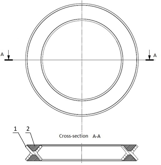
The semimetal gasket with an elastic metal core, 1 - metal core, 2 - flexible material
The elastic material filling the metal core can be expanded graphite, PTFE or expanded mica. In this work, expanded graphite was adopted as the flexible material, while steel 1.4301 was used to make the metal core. The purpose of the numerical analysis conducted in the first part of this paper was to determine the optimal dimensions that describe the geometry of the cross-section of the metal core. The optimal solution was one with high elasticity and high elastic recovery. As a result, such a solution should translate into a high tightness class. At the final stage of the work, an experimental verification of the optimal solution was carried out. The experiment assumed the determination of the characteristics describing the elastic-plastic properties and the characteristics of the tightness.
3 Formulation of the optimization problem
The optimal design of the gasket used in flange-bolted joints is one that should be characterized by:
high tightness at low assembly loads,
high elasticity,
high mechanical strength,
high corrosion resistance,
high resistance to creep and relaxation.
All these properties are associated with the selection of appropriate materials. In a typical semimetal gasket, the metal element usually provides elasticity and strength, whereas the flexible material (due to its high plasticity) provides leakage proofness. In the case where a sealing node is subjected to an alternating load (temperature, pressure, mechanical vibrations), the level of tightness is determined by another gasket parameter, i.e. elastic recovery. The elastic recovery (in relation to the function of the sealing in the flange-bolted joint) can be characterized as the ability to maintain the highest possible contact pressure with a decreasing load on the bolts. An impact of the gasket’s elasticity on the load distribution and elastic recovery in the joint’s components is shown in Figure 2.
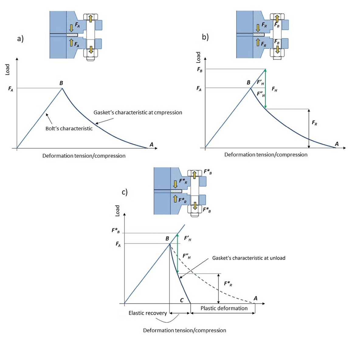
The influence of the stiffness of the joint’s elements on the residual force
Assuming that bolts deform elastically throughout the entire load range and that the stiffness of the compressed elements (flanges, nuts, washers and gaskets) can be represented by one of the non-linear gasket’s characteristics, then the assembly state of the joint can be represented by means of the chart stiffness shown in Figure 2a). The common point of the bolt’s characteristics and gasket’s characteristics is determined by assembly force (FA). In the case of an operating load, the pressure of the sealed medium acting on the blind ends (covers, bends) causes hydrostatic force (FH) – see Figure 2b). As a result, this force causes the increase of the bolt’s load (FB), whereas the gasket’s load (deformation) decreases to the residual clamping force (FR). The smaller the residual clamping force, the smaller the tightness of the joint. A proportion of the hydrostatic force, which increases the bolt’s load
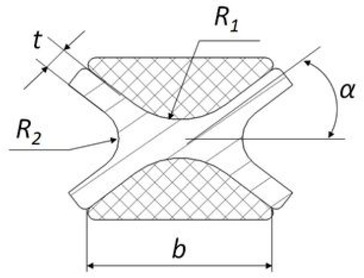
The characteristic dimensions of the gasket
where R1 (mm) was the rounding radius of the bottom in the front groove, R2 (mm) was the rounding radius of the bottom in the lateral grooves, α (∘) was the angle of the lateral grooves, t (mm) was the thickness of the segment, and b (mm) was the width of the gasket. The enforcing parameter was the gasket’s deformation UZ = 3 mm.
The independent variables were the parameters describing the strength of materials, which determined some limitations of the searched area of the optimal design. The first limitation was the allowable contact pressure of the expanded graphite equal to 180 MPa. This limitation was written as:
The second limitation involved not exceeding the value of the ultimate stress of the metal core equal to 550 MPa:
The third limitation was obtaining the minimum graphite contact pressure pmin = 10 MPa, which ensures the tightness at the level of 0.1 mg/ sm. This limitation can be written as:
A graphic description of the optimization process is shown in Figure 4. Based on the above objective function and the imposed limitations, the objective functions can be presented as follows:
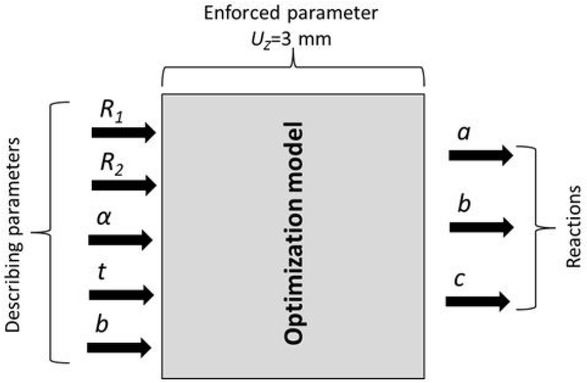
Model of the gasket’s optimization
Based on the assumed range of the parameters that describe the geometries of the core’s cross-section, 210 models of the gasket’s design were generated. Examples of the solutions are presented in Figure 5.
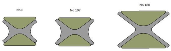
The exemplary variants of the gasket’s cross-section
4 Numerical calculations
The Finite Element Method was used as a tool to optimize the structure.
Numerical models of the 210 considered variants were prepared as axisymmetric. Each of the numerical models consisted of a gasket located between two plates representing the compression surfaces of a hydraulic press. Higher-order structural finite elements were selected to discretize areas of individual parts. Depending on the gasket’s design, the number of finite elements ranged from 3200 to 7300. The mesh density in the expanded graphite was 0.1 mm, whereas in the metal core it was 0.2 mm. The mesh density of the metal plates ranged from 0.1 mm to 1 mm. The discretization of the exemplary model is shown in Figure 6a). Each contacting surface was set as frictional. The friction coefficient on the contact area between the metal-graphite was 0.4, while the metal-metal one was 0.2. The boundary conditions of the model were: the fixing of the lower plate - preventing its displacement in the axial direction, and the displacement of the upper plate by UZ = 3 mm - realizing the compression process of the gasket - Figure 6b).
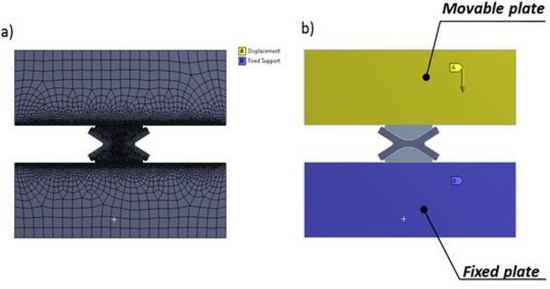
The numerical model of the gasket’s compression: a) discretization of particular areas, b) boundary conditions
The model representing metal parts was an isotropic, bilinear elasto-plastic one in which the value of elasticity modulus was E = 206000 MPa, Poisson’s ratio v = 0.3, and the material strengthening module in the plastic zone E U = 8000 MPa – see Figure 7a). To reflect the properties of the expanded graphite, an isotropic, multi-linear material model was adopted. Its characteristics (being the result of experimental measurements) are shown in Figure 7b). This, of course, was a simplification of the graphite’s properties, since this material exhibits high anisotropy at a high compression level.
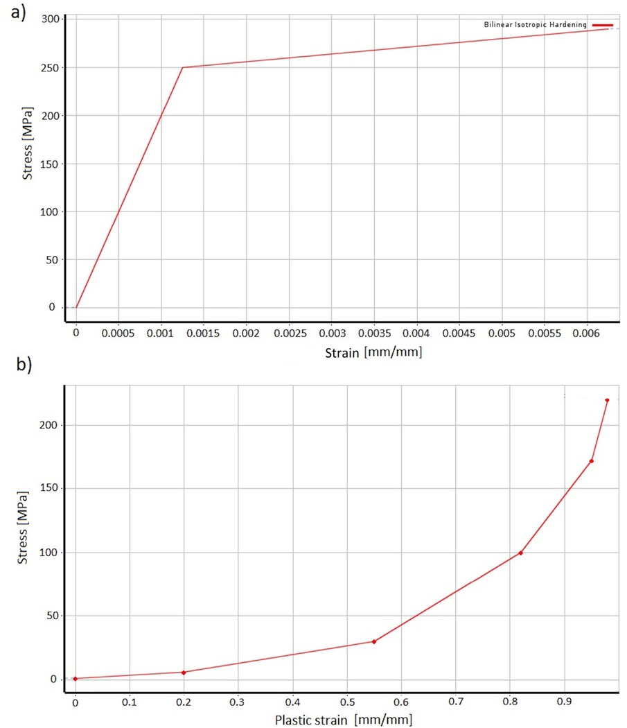
Characteristics of the materials: a) isotropic bilinear model of steel, b) isotropic multilinear model of expanded graphite
4.1 Numerical results
Figure 8 shows the visualization of the compression process of gasket model No. 180. This variant met only two limitations concerning the strength of the materials. At a compression of UZ = 3 mm, the value of the maximum stress in the metal core was Smax = 420.7 MPa, and the maximum stress in the graphite was Smax = 18.8 MPa. However, this variant did not meet the limitation resulting from the minimum contact pressure. The contact pressure on the gasket’s surface at a maximum compression UZ = 3 mm was 4.3 MPa. Based on the numerical calculations, only 7 out of 210 gasket variants met all the imposed limitations.
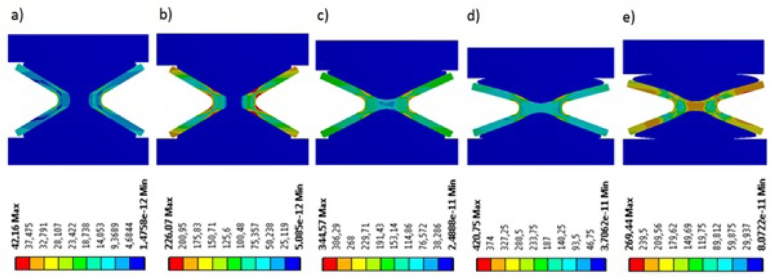
Equivalent stress distribution in MPa of gasket model No. 180: a) compression 0.3 mm, b) compression 0.5 mm, c) compression 1.5 mm, d) compression 3 mm, e) decompression 1.5 mm
Figure 9 presents the compression process of variant No. 110. The stress in the metal core at a compression of 3 mm was Smax = 507.8 MPa, the stress in the graphite was Smax = 48.2 MPa, and the contact pressure was 21.3 MPa. Figure 10 presents the deformation characteristics of this variant. The maximum force necessary to deform the gasket by 3 mm was about 35 kN.
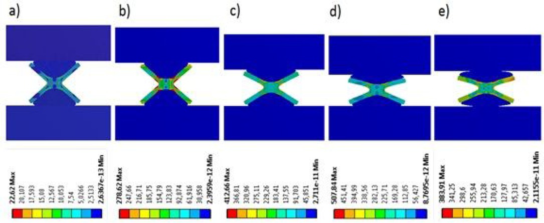
Equivalent stress distribution in MPa of gasket model No. 110: a) compression 0.3 mm, b) compression 0.5 mm, c) compression 1.5 mm, d) compression 3 mm, e) decompression 1.5 mm
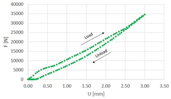
Compression characteristics of gasket variant No. 110
The average angle of the unload curve was 62 degrees, and it was the minimum of the objective function. In addition, a small hysteresis can be observed, i.e. the area located between the load and unload curves. A compilation of the stiffness characteristics of the variants that met the imposed limitations is shown in Figure 11. Table 1 contains the values of the inclination angles of the unload curve, parameters j2 that determine the relative value of the hysteresis area, and the dimensions of the gasket’s cross-section.
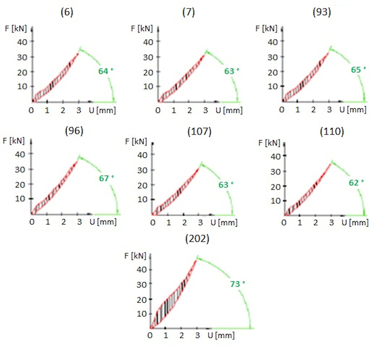
The stiffness characteristics of the selected gasket’s variants that met all the limitations
Compilation of the average values of the inclination angles of the unload curve, the relative hysteresis surface area, and the characteristic dimensions of the gaskets that met all the limitations
| Variant | Area | β | R1 | R2 | α | b | t |
|---|---|---|---|---|---|---|---|
| No | j2 | deg | mm | mm | ∘ | mm | mm |
| 6 | 0.964 | 64 | 2 | 2 | 75 | 8 | 0.7 |
| 7 | 0.891 | 63 | 2 | 2 | 75 | 10 | 0.7 |
| 93 | 0.968 | 65 | 2 | 3 | 75 | 10 | 0.7 |
| 96 | 0.85 | 67 | 2 | 1 | 75 | 8 | 0.7 |
| 107 | 0.86 | 63 | 2 | 3 | 75 | 10 | 0.7 |
| 110 | 0.731 | 62 | 3 | 0.5 | 75 | 10 | 0.7 |
| 202 | 1.906 | 73 | 6 | 2 | 65 | 16 | 1 |
5 Experimental research
In order to verify the numerical calculations of the optimal gasket’s structure, experimental tests were carried out. In the first part of the experiment, the elastic behavior of the gasket was determined. In the second part, the leakage characteristic of the optimal gasket variant was determined.
5.1 Elasticity and elastic recovery
5.1.1 Test rig
Figure 12 presents the test stand.
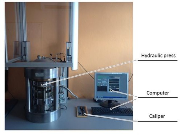
Test rig for the determination of the gasket’s elastic properties
The main element was a computer-controlled hydraulic press. The other elements of the test rig included a hydraulic press control system and a computer that records the course of the test. The parameters of the hydraulic press were: the maximum compressive force of 1 MN, the maximum size of the tested gasket (outer diameter) of 170 mm, the maximum operating temperature of 300 C degrees.
5.1.2 The test procedure
The procedure was as follows: the gasket was placed in a concentric way on the lower plate of the hydraulic press. The upper plate of the press was set to touch the top of the gasket’s surface. Once a contact between the gasket and the upper plate was reached, the maximum compression value UZ = 3mm was set. Due to displacement sensors mounted between the upper and lower plates, as well as an extensometer in the lower plate, the dependence between the compressing force and the gasket’s displacement was recorded.
5.1.3 Test results
Figure 13 presents the experimentally determined deformation characteristics of the tested gasket together with the characteristics obtained by means of numerical calculations. It can be stated that despite simplifications adopted in the numerical model of the graphite, the obtained characteristics did not differ significantly from the experimental characteristics. The angle of inclination of the unloading curve was 65 degrees, while the force causing the compression of 3 mmwas 38 kN. The sample of the gasket after the compression test is shown in Figure 14.
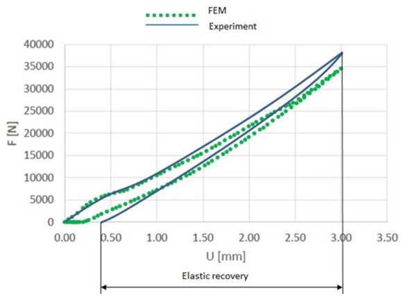
Characteristics of the gasket’s stiffness
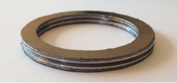
Gasket after the compression test
5.2 Leakage level
In order to confirm the optimal gasket solution, a leakage test was performed. To reflect the real operating conditions of the gasket, the test was carried out on a flange-bolted joint.
5.2.1 Test rig
The test stand presented in Figure 15 consisted of two flanges with dimensions DN40 and PN40, four M16 bolts with strength class 8.8, a glass cover constituting a collective collector, a helium detector, a helium reservoir, and a vacuum pump connected to the detector.
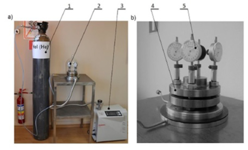
Test rig for the leakage test: 1- helium reservoir, 2-glass cover, 3 – helium detector, 4- flange bolted joint with gasket, 5 micrometric measuring system
Each bolt was equipped with a micrometer measurement system, which is shown in Figure 16.
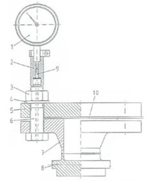
Micrometric system to measure the elongation of bolts
This solution was based on the guidelines included in the EN 28091-2 standard. The idea of such a solution was to measure the length of a metal rod (9). When tightening the nuts (3), the micrometer gauges (1) mounted on the ends of the bolts indicated the current value of the rod protruding above the end of the bolt. Based on such measurement, the elongation of a given bolt can be directly assessed, and after determining the characteristics describing the relationship between the bolt’s tensile force and its elongation, the value of its tension can be determined. Exemplary bolt characteristics are shown in Figure 17.
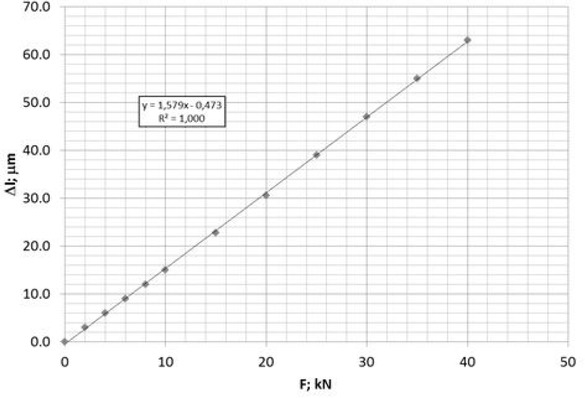
Characteristics describing the dependence of the bolt’s elongation in the function of tensile force
5.2.2 Test procedure
After placing the gasket on the lower flange, the upper flange was mounted and the nuts were tightened with a small torque. Afterwards, the micrometer sensors were installed. The test consisted of a gradual increase of the bolt’s load and then a gradual decrease. Ultimately, four bolt tension values were determined for the loading of 10, 20, 30 and 40 kN, and three values for the reduction of the load, i.e. 30, 20 and 10 kN. In each load point, 10 bar of helium pressure was applied on the joint, a glass cover was put on the joint and the level of leakage was measured.
5.2.3 Results
Figure 18 presents the tightness characteristics of the optimal gasket solution. At the maximum gasket load, i.e. 40 kN, the measured leakage value was 0.0037 mg/s·m. Very optimistic results of the leakage level were obtained when the load on the bolts was reduced. The slope of the unloading leakage curve was inclined at a small angle to the abscissa. The leakage level during unloading of the gasket’s compression at 10 kN was approximately 0.1 mg/s·m. This effect was due to the high elastic recovery of the metal core and the good plastic properties of the flexible material.
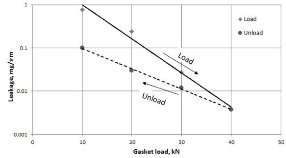
Tightness characteristic of the optimal gasket solution
6 Conclusions
Based on the numerical calculations and experimental tests, the results can be concluded in the following way:
The proper shaping of the metal gasket’s core has a major influence on its elasticity, as well as on the amount of absorbed and dissipated energy. The measure of dissipated energy was the area of the hysteresis loop formed between the load and unload gasket curves.
A greater hysteresis loop causes the unload gasket curve to deviate from the load curve.
Greater deviations of the unload gasket curve from the load curve cause the elastic recovery to be smaller.
An excessive increase of the gasket’s elasticity leads to an excessive increase of the stress in the metal core.
As the load on the bolts gradually decreases, the gasket with an increased elastic recovery maintains a high level of tightness of the flange-bolt joint.
• After the optimization process, only 7 out of 210 gasket solutions were revealed. These solutions met all the imposed limitations. Nonetheless, only gasket design No. 210 exhibited the minimum of the objective function, and therefore this solution has been recognized as the optimal design.
The optimal gasket design provides a moderate and reduced stress in the expanded graphite (48.2MPa) and in the metal core (507.8 MPa), but what is more important, the pressure when compressing the gasket to 3 mm was equal to 21.3 MPa.
The optimal gasket design was experimentally tested. The experimental results showed that the compression characteristics slightly differ from the numerical results. These small deviations can be caused by the adapted isotropic material model of the expanded graphite.
The leakage test of the optimal gasket showed that under a compression load of 40 kN, the gasket provides a leakage level of 0.0037mg/s·m. Moreover, during the unloading, the gasket keeps a very low leakage level of approximately 0.1 mg/s·m.
7 Summary
The paper presents a new design of a semimetal gasket, which was subjected to the optimization process. The main objective function was to achieve the maximum elastic recovery of a gasket at imposed functional and strength limitations. The objective function was described indirectly in the form of the required minimum angle of the gasket’s unload curve inclination, which was a measure of the average value of the elastic modulus at unloading. Strength limitations resulted from not exceeding the ultimate stress of the materials, while functional limitations imposed the achievement of a proper contact pressure that ensures a given level of tightness class. The geometry of the cross-section of the metal core was determined by five descriptive parameters. As a result of the interrelationship of these parameters, 210 construction models were created and subjected to compression simulations. This problem was solved by means of the Finite Element Method. The gasket variant fulfilling the imposed limitations and the required minimum of objective function was tested experimentally. In the first stage, a compression test was carried out, which allowed the gasket’s elasticity and elastic recovery to be determined. In the second stage, a leak test was carried out. At the maximum gasket load of 40 kN, the tightness level was higher than 0.01 mg/s·m.
Acknowledgement
Calculations have been carried out using resources provided by Wroclaw Centre for Networking and Supercomputing (http://wcss.pl), grant No. 444
References
[1] Kidam K., Hassin M. H., Enhancement of inherent safety and accident prevention in chemical industry by reviewing past accidents, Journal of Chemical and Natural Resources Engineering, 2008 pp 75-86.Suche in Google Scholar
[2] Sonnemans PJ, Korvers PM. Accidents in the chemical industry: are they foreseeable? J Loss Prev Process Ind. 2006;19(1):1–12.10.1016/j.jlp.2005.03.008Suche in Google Scholar
[3] Furtek A. Review of hazardous of the pipeline accidents. Centre of Excellence at the Institute of Atomic Energy; 2004.Suche in Google Scholar
[4] Jaszak P, Adamek K. Design and analysis of the flange-bolted joint with respect to required tightness and strength. Open Eng. 2019;9(1):338–49.10.1515/eng-2019-0031Suche in Google Scholar
[5] Fukuoka T, Nomura M, Nishikawa T. Analysis of Thermal and Mechanical Behavior of Pipe Flange Connections by Taking Account of Gasket Compression Characteristics at Elevated Temperature. J Press Vessel Technol. 2012;134(2):021202.10.1115/1.4005388Suche in Google Scholar
[6] Zylinski B, Buczkowski R. Analysis of bolted joint using the finite element method, Arch. Mech. Eng., Vol. LVII, 2010, Number 3.10.2478/v10180-010-0015-xSuche in Google Scholar
[7] Jaszak P. The elastic serrated gasket of the flange bolted joints. Int J Press Vessels Piping. 2019;176:103954.10.1016/j.ijpvp.2019.103954Suche in Google Scholar
[8] Jaszak P. A new solution of the semi-metallic gasket increasing tightness level. Open Eng. 2019;9(1):329–37.10.1515/eng-2019-0030Suche in Google Scholar
[9] Suggs S., Meyer R., Kolb S., Low stress/anti-buckling spiral wound gasket, International Application Published Under The Patent Cooperation Treaty, WO 2017/087643 A2.Suche in Google Scholar
[10] Attoui H, Bouzid AH, Waterland JA. Buckling and lateral pressure in spiral wound gaskets, Proceedings of the ASME 2014, Pressure Vesel and Piping Conference 2014, Volume 2: Computer Technology and Bolted Joints, Anaheim, California, USA, July 20–24, (2014), pp. 1-7. https://doi.org/10.1115/PVP2014-2844910.1115/PVP2014-28449Suche in Google Scholar
[11] Winter JR, Leon GF. Radially Inward Buckling of Spiral Wound Gaskets. American Society of Mechanical Engineers, Pressure Vessels and Piping Division. PVP-Vol. 1985;98:111–6.Suche in Google Scholar
[12] Mueller RT. Recent buckling experiences with spiral wound flexible graphite filled gaskets, American Society of Mechanical Engineers, Pressure Vessels and Piping Division PVP. Volume 326. Computer Technology – Applications and Methodology; 1996. pp. 23–34.Suche in Google Scholar
[13] Veiga JC, Cipolatti CF, Kavanagh N, Castro F, Zandona V. Serrated Metal Graphite Faced Gaskets for Ring Joint Flanges, Conference: ASME. Pressure Vessels and Piping Conference; 2012.10.1115/PVP2012-78349Suche in Google Scholar
[14] Jaszak P., Uszczelnienie metaloplastyczne połączeń kołnierzowośrubowych, Opis patentowy PL 231054 B1.Suche in Google Scholar
[15] Jaszak P. Adaptation of a highly compressible elastomeric material model to simulate compressed expanded graphite and its application in the optimization of a graphite-metallic structure’. J Braz Soc Mech Sci Eng. 2020;42(5):224.10.1007/s40430-020-02311-8Suche in Google Scholar
© 2021 P. Jaszak, published by De Gruyter
This work is licensed under the Creative Commons Attribution 4.0 International License.
Artikel in diesem Heft
- Regular Articles
- Electrochemical studies of the synergistic combination effect of thymus mastichina and illicium verum essential oil extracts on the corrosion inhibition of low carbon steel in dilute acid solution
- Adoption of Business Intelligence to Support Cost Accounting Based Financial Systems — Case Study of XYZ Company
- Techno-Economic Feasibility Analysis of a Hybrid Renewable Energy Supply Options for University Buildings in Saudi Arabia
- Optimized design of a semimetal gasket operating in flange-bolted joints
- Behavior of non-reinforced and reinforced green mortar with fibers
- Field measurement of contact forces on rollers for a large diameter pipe conveyor
- Development of Smartphone-Controlled Hand and Arm Exoskeleton for Persons with Disability
- Investigation of saturation flow rate using video camera at signalized intersections in Jordan
- The features of Ni2MnIn polycrystalline Heusler alloy thin films formation by pulsed laser deposition
- Selection of a workpiece clamping system for computer-aided subtractive manufacturing of geometrically complex medical models
- Development of Solar-Powered Water Pump with 3D Printed Impeller
- Identifying Innovative Reliable Criteria Governing the Selection of Infrastructures Construction Project Delivery Systems
- Kinetics of Carbothermal Reduction Process of Different Size Phosphate Rocks
- Plastic forming processes of transverse non-homogeneous composite metallic sheets
- Accelerated aging of WPCs Based on Polypropylene and Birch plywood Sanding Dust
- Effect of water flow and depth on fatigue crack growth rate of underwater wet welded low carbon steel SS400
- Non-invasive attempts to extinguish flames with the use of high-power acoustic extinguisher
- Filament wound composite fatigue mechanisms investigated with full field DIC strain monitoring
- Structural Timber In Compartment Fires – The Timber Charring and Heat Storage Model
- Technical and economic aspects of starting a selected power unit at low ambient temperatures
- Car braking effectiveness after adaptation for drivers with motor dysfunctions
- Adaptation to driver-assistance systems depending on experience
- A SIMULINK implementation of a vector shift relay with distributed synchronous generator for engineering classes
- Evaluation of measurement uncertainty in a static tensile test
- Errors in documenting the subsoil and their impact on the investment implementation: Case study
- Comparison between two calculation methods for designing a stand-alone PV system according to Mosul city basemap
- Reduction of transport-related air pollution. A case study based on the impact of the COVID-19 pandemic on the level of NOx emissions in the city of Krakow
- Driver intervention performance assessment as a key aspect of L3–L4 automated vehicles deployment
- A new method for solving quadratic fractional programming problem in neutrosophic environment
- Effect of fish scales on fabrication of polyester composite material reinforcements
- Impact of the operation of LNG trucks on the environment
- The effectiveness of the AEB system in the context of the safety of vulnerable road users
- Errors in controlling cars cause tragic accidents involving motorcyclists
- Deformation of designed steel plates: An optimisation of the side hull structure using the finite element approach
- Thermal-strength analysis of a cross-flow heat exchanger and its design improvement
- Effect of thermal collector configuration on the photovoltaic heat transfer performance with 3D CFD modeling
- Experimental identification of the subjective reception of external stimuli during wheelchair driving
- Failure analysis of motorcycle shock breakers
- Experimental analysis of nonlinear characteristics of absorbers with wire rope isolators
- Experimental tests of the antiresonance vibratory mill of a sectional movement trajectory
- Experimental and theoretical investigation of CVT rubber belt vibrations
- Is the cubic parabola really the best railway transition curve?
- Transport properties of the new vibratory conveyor at operations in the resonance zone
- Assessment of resistance to permanent deformations of asphalt mixes of low air void content
- COVID-19 lockdown impact on CERN seismic station ambient noise levels
- Review Articles
- FMEA method in operational reliability of forest harvesters
- Examination of preferences in the field of mobility of the city of Pila in terms of services provided by the Municipal Transport Company in Pila
- Enhancement stability and color fastness of natural dye: A review
- Special Issue: ICE-SEAM 2019 - Part II
- Lane Departure Warning Estimation Using Yaw Acceleration
- Analysis of EMG Signals during Stance and Swing Phases for Controlling Magnetorheological Brake applications
- Sensor Number Optimization Using Neural Network for Ankle Foot Orthosis Equipped with Magnetorheological Brake
- Special Issue: Recent Advances in Civil Engineering - Part II
- Comparison of STM’s reliability system on the example of selected element
- Technical analysis of the renovation works of the wooden palace floors
- Special Issue: TRANSPORT 2020
- Simulation assessment of the half-power bandwidth method in testing shock absorbers
- Predictive analysis of the impact of the time of day on road accidents in Poland
- User’s determination of a proper method for quantifying fuel consumption of a passenger car with compression ignition engine in specific operation conditions
- Analysis and assessment of defectiveness of regulations for the yellow signal at the intersection
- Streamlining possibility of transport-supply logistics when using chosen Operations Research techniques
- Permissible distance – safety system of vehicles in use
- Study of the population in terms of knowledge about the distance between vehicles in motion
- UAVs in rail damage image diagnostics supported by deep-learning networks
- Exhaust emissions of buses LNG and Diesel in RDE tests
- Measurements of urban traffic parameters before and after road reconstruction
- The use of deep recurrent neural networks to predict performance of photovoltaic system for charging electric vehicles
- Analysis of dangers in the operation of city buses at the intersections
- Psychological factors of the transfer of control in an automated vehicle
- Testing and evaluation of cold-start emissions from a gasoline engine in RDE test at two different ambient temperatures
- Age and experience in driving a vehicle and psychomotor skills in the context of automation
- Consumption of gasoline in vehicles equipped with an LPG retrofit system in real driving conditions
- Laboratory studies of the influence of the working position of the passenger vehicle air suspension on the vibration comfort of children transported in the child restraint system
- Route optimization for city cleaning vehicle
- Efficiency of electric vehicle interior heating systems at low ambient temperatures
- Model-based imputation of sound level data at thoroughfare using computational intelligence
- Research on the combustion process in the Fiat 1.3 Multijet engine fueled with rapeseed methyl esters
- Overview of the method and state of hydrogenization of road transport in the world and the resulting development prospects in Poland
- Tribological characteristics of polymer materials used for slide bearings
- Car reliability analysis based on periodic technical tests
- Special Issue: Terotechnology 2019 - Part II
- DOE Application for Analysis of Tribological Properties of the Al2O3/IF-WS2 Surface Layers
- The effect of the impurities spaces on the quality of structural steel working at variable loads
- Prediction of the parameters and the hot open die elongation forging process on an 80 MN hydraulic press
- Special Issue: AEVEC 2020
- Vocational Student's Attitude and Response Towards Experiential Learning in Mechanical Engineering
- Virtual Laboratory to Support a Practical Learning of Micro Power Generation in Indonesian Vocational High Schools
- The impacts of mediating the work environment on the mode choice in work trips
- Utilization of K-nearest neighbor algorithm for classification of white blood cells in AML M4, M5, and M7
- Car braking effectiveness after adaptation for drivers with motor dysfunctions
- Case study: Vocational student’s knowledge and awareness level toward renewable energy in Indonesia
- Contribution of collaborative skill toward construction drawing skill for developing vocational course
- Special Issue: Annual Engineering and Vocational Education Conference - Part II
- Vocational teachers’ perspective toward Technological Pedagogical Vocational Knowledge
- Special Issue: ICIMECE 2020 - Part I
- Profile of system and product certification as quality infrastructure in Indonesia
- Prediction Model of Magnetorheological (MR) Fluid Damper Hysteresis Loop using Extreme Learning Machine Algorithm
- A review on the fused deposition modeling (FDM) 3D printing: Filament processing, materials, and printing parameters
- Facile rheological route method for LiFePO4/C cathode material production
- Mosque design strategy for energy and water saving
- Epoxy resins thermosetting for mechanical engineering
- Estimating the potential of wind energy resources using Weibull parameters: A case study of the coastline region of Dar es Salaam, Tanzania
- Special Issue: CIRMARE 2020
- New trends in visual inspection of buildings and structures: Study for the use of drones
- Special Issue: ISERT 2021
- Alleviate the contending issues in network operating system courses: Psychomotor and troubleshooting skill development with Raspberry Pi
- Special Issue: Actual Trends in Logistics and Industrial Engineering - Part II
- The Physical Internet: A means towards achieving global logistics sustainability
- Special Issue: Modern Scientific Problems in Civil Engineering - Part I
- Construction work cost and duration analysis with the use of agent-based modelling and simulation
- Corrosion rate measurement for steel sheets of a fuel tank shell being in service
- The influence of external environment on workers on scaffolding illustrated by UTCI
- Allocation of risk factors for geodetic tasks in construction schedules
- Pedestrian fatality risk as a function of tram impact speed
- Technological and organizational problems in the construction of the radiation shielding concrete and suggestions to solve: A case study
- Finite element analysis of train speed effect on dynamic response of steel bridge
- New approach to analysis of railway track dynamics – Rail head vibrations
- Special Issue: Trends in Logistics and Production for the 21st Century - Part I
- Design of production lines and logistic flows in production
- The planning process of transport tasks for autonomous vans
- Modeling of the two shuttle box system within the internal logistics system using simulation software
- Implementation of the logistics train in the intralogistics system: A case study
- Assessment of investment in electric buses: A case study of a public transport company
- Assessment of a robot base production using CAM programming for the FANUC control system
- Proposal for the flow of material and adjustments to the storage system of an external service provider
- The use of numerical analysis of the injection process to select the material for the injection molding
- Economic aspect of combined transport
- Solution of a production process with the application of simulation: A case study
- Speedometer reliability in regard to road traffic sustainability
- Design and construction of a scanning stand for the PU mini-acoustic sensor
- Utilization of intelligent vehicle units for train set dispatching
- Special Issue: ICRTEEC - 2021 - Part I
- LVRT enhancement of DFIG-driven wind system using feed-forward neuro-sliding mode control
- Special Issue: Automation in Finland 2021 - Part I
- Prediction of future paths of mobile objects using path library
- Model predictive control for a multiple injection combustion model
- Model-based on-board post-injection control development for marine diesel engine
- Intelligent temporal analysis of coronavirus statistical data