Heat treatment and tensile test of 3D-printed parts manufactured at different build orientations
-
Ming-Lang Tseng


Abstract
Additive manufacturing has been gaining popularity in many industries and has made significant growth over the last 5 years. Many industries use additive manufacturing three-dimensional (3D) printing to produce complex shape objects that is a challenge to be manufactured by casting or conventional methods. In this study, the impact of heat treatment and build orientation is examined for the mechanical characteristics of 3D-printed parts. The study used samples constructed of titanium alloy Ti-6Al-4V, which is frequently used in AM applications. The parts were printed at various build orientations such as 0°, 45°, and 90°. Following printing, the samples underwent four distinct heat-treatments at 0, 700, 800, and 900°C. The variation in mechanical properties (Young’s modulus, strain-stress, and tensile strength) has been monitored to determine the best heat treatment and tilt orientation to obtain the best mechanical properties. These findings provide a systematic analysis and support the 3D printing of the parts used with a desired mechanical strength.
1 Introduction
3D printing conditions can considerably impact the quality, accuracy, and reliability of printed parts [1,2,3,4]. Specific printing configurations can vary depending on the printer model, material, and desired impact [5,6]. Three-dimensional (3D) printing has become a game-changer in various industries like healthcare, aerospace, automotive, and manufacturing. It is known for its ability to produce complex shapes and custom parts with precision, making it a popular choice for modelling and finished products. However, the building orientation of the object on the build plate plays a crucial role in achieving the desired quality and precision of the printed object. Building orientation refers to the angle and direction of the object on the build plate, and it affects the strength, surface quality, and precision of the finished product [7]. To achieve this, a heat treatment procedure is often used as a post-processing step. This involves heating the object to a specific temperature, holding it at that temperature for a certain period of time, and then cooling it down. By doing this, we can change the object’s microstructure, which can improve its strength, ductility, and toughness [8,9]. Eryildiz et al. in their research studies clearly shows the variations in the ultimate tensile strength (UTS) and percentage of maximum elongation. Seven samples at different temperatures are used for the experimentation [10]. At the no heating or the built-in conditions, the UTS and yield strength (YS) are given as 1,191 and 908 MPa, respectively. As the temperature rises from 450 to 550°C the UTS increases the values to 1,198, 1,211, and 1,220 MPa, respectively. Similarly, the YS increases to 863, 890, and 917 MPa, respectively. Then, as the temperature rises to 600 and 650°C it shows a significant dip in the UTS and YS values as 1,167, 1,117, 886, and 879 MPa, respectively. On the other hand, the rate of elongation continuously increases as the temperature increases from 9.2 to 12.3%. It is evident that the optimum temperature at which it shows the maximum stress–strain values is at 550°C. After this temperature, the sample shows a significant dip in the values of both stress and strain. So, up to a certain temperature, the positive hike is clear and after that the stress and strain will decrease in the Ti-6Al-4V [11]. Zhilyaev et al. correlated the relationship between stress and strain relation at various post-heat treatment temperatures [12]. The effect of cooling the heated sample at various temperatures and by various cooling methods is clearly stated and studied in the previous research [13]. The ideal post-heat treatment candidate was found to be the solid solution, which was heated at 800°C for 2 h followed by water cooling plus aging at 500°C for 4 h followed by furnace cooling because it increased YS and UTS by 3.33 and 12.85%, respectively, while the tensile fracture elongation (EL) decreased by 3.37% in comparison to the samples that were not heated [14]. The maximum strain attained was at the time of post-heat treatment at 800°C for a period of 2 h with air cooling. But when the time of heat treatment was extended to 4 h, the strain tends to suddenly decrease but shows a hike in strength. This has opted as the optimum post-heat treatment temperature for the Ti-6Al-4V alloy to provide the maximum strength among all the heat treatment conditions. In contrast, in case of furnace cooling for the titanium alloy, the heating for 800°C for 2 h and 500°C for 4 h do not show any significant variation in the strain and is considered too minimal. However, heating for a long time at a less temperature tends to show an increase in the strength of the titanium alloy, rather than providing a high temperature for a short period of time. After a certain limit of increase in strength when the heating continues, it shows a sudden dip in the strength of the alloy. Gorji et al. in their research reported the particle size distribution of 316L powders used in 3D printing using tomography and microscopy, and nanoindentation [15].
In this study, 3D printed parts were manufactured at different tilt angles and were heat-treated at different temperatures. The parts were subject to ultimate tensile testing, strain-stress analysis, Young’s modulus measurements, and surface roughness analysis both before and after heat treatment at various temperature levels. These comprehensive results provide a methodical assessment that supports the use of 3D printing to achieve desired mechanical strength in the fabricated components.
2 Experimental methodology
Based on the required parameters and print conditions as stated in Table 1, an EOS printer was used, and the 3D-printed parts are produced using Ti-6Al-4V alloy. The laser power was set at 160 W. The thickness of each layer is set to be 60 μm. The point distance that is the distance from the printing bed and the laser source is set to be 40 μm, this distance should be properly maintained to get the desired characteristics for the product. The laser exposure time is set to be 180 μs as increasing or decreasing the time may affect the quality of the printed part. The hatch spacing or the distance between each layer is set to be 90 μm. To obtain the desired shape as per the pre-designed programme, the scan speed is set to be 220 mm/s. The oxygen concentration is a vital component that needs to be properly maintained throughout the 3D printing process, and in this case, the oxygen concentration is set to be 0.1%. The laser spot size determines the amount of area in which the energy needs to be dissipated and, in this case, it is set as 75 μm. All these print conditions need to be properly maintained throughout the 3D printing process so that the decided characteristic of the product printed with titanium powder can be attained. All the physical and mechanical properties are thus studied based on the above pre-set conditions and temperature ranges. The parts were standard tensile test bars as shown in Figure 1.
3D Printing parameters used to print the parts
| Print conditions | Parameters |
|---|---|
| Laser power (W) | 160 |
| Layer thickness (μm) | 60 |
| Point distance (μm) | 40 |
| Exposure time (μs) | 180 |
| Hatch spacing (μm) | 90 |
| Scan speed (mm/s) | 220 |
| Oxygen concentration (%) | 0.1 |
| Laser spot size (μm) | 75 |

The tensile test bars printed at different build orientations.
3 Results and discussion
The following results are obtained after the experimentation using the alloy printed parts at various temperatures and build orientations.
3.1 Build orientation (ϴ)
The overall quality, mechanical characteristics, and functionality of printed products are significantly influenced by the construction orientation of the individual elements. The orientation in which a 3D printed part is placed or layered during the additive manufacturing process is called the build orientation. It entails how the part is positioned in relation to the build plate or printing platform. The SEM images taken from the parts printed at different build orientation has been shown in Figure 2. These images were processed by ImageJ [16,17,18]. Certain conclusions about the microstructural properties can be obtained by processing the SEM images.

SEM image of the sample printed at ϴ = 0°, 45°, and 90° build orientations.
Figure 3 shows the directionality histograms of the tensile bars printed at three different tilt orientations. The part printed at 90° orientation has shown less variation for a wider range of directions and therefore, is the best orientation to print the samples. The horizontally placed sample at 0° shows most variation at 0 direction and thus would negatively influence the mechanical properties of the sample.

Directionality histogram for the tensile bars printed at 0°, 45°, and 90° tilt orientations.
3.2 Relationship between built orientation and surface roughness
Unevenness and deviations in a surface’s texture can be referred to as surface roughness. Surface roughness is a key factor in influencing the quality and usefulness of the printed object when utilizing titanium powder for 3D printing of the parts especially for biomedical applications and aviation industry. Figure 4 shows the variation in surface roughness (obtained by AFM) at various build orientation angles for the 3D-printed parts.
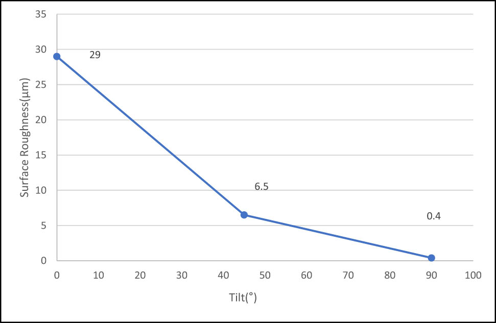
Variation in surface roughness vs the build tilt angle.
It is understood that the surface roughness will be maximum at 0° printing angle which is 29 μm. At 45° printing angle, the surface roughness will be 6.5 μm and it will be the least roughness (0.4 μm) for parts printed vertically at 90° angle. At 0° and 45° tilt angles, the deposition of the melted particle will be uneven, and this may cause an increase in the surface roughness. So, in order to achieve a printed part with minimum surface roughness, the build orientation should be selected as 90° to reduce the uneven melting of the particles and improved solidification post-print. At 0° and 45° tilt angles, the surface roughness tends to be higher compared to other angles due to the printing process’s inherent characteristics and the orientation of the layers when utilizing titanium powder for 3D printing. At 0° and 45° angles, the layering of the material might result in a greater tendency for stair-stepping effects or unevenness between layers. This can cause an increased surface roughness due to the way the material is deposited and solidified in these orientations. Depending on the specific 3D printing technique used, supports might be needed to maintain stability during printing. At certain angles, such as 0° and 45°, the requirement for additional supports or the way they are applied might contribute to increased surface roughness. The angle of deposition at 0° and 45° could lead to a higher likelihood of material accumulation or uneven distribution, resulting in a rougher surface finish compared to other angles. The tool path followed by the 3D printer’s nozzle or laser might be less optimized or less efficient at these angles, affecting the uniformity of material application and consequently causing higher surface roughness. The variations in surface roughness based on different build orientation angles in the 3D printing process are crucial to understand for industries like biomedical applications and aviation where surface quality directly impacts the functionality and reliability of the printed parts.
3.3 Build orientation, Young’s modulus, and UTS
The build orientation in 3D printing defines the direction in which the material is arranged in layers all through the printing process. For titanium alloy, the connection between Young’s modulus and UTS might change depending on its building orientation during 3D printing [19,20]. The elastic modulus, commonly referred to as Young’s modulus (E r), is a measurement of a material’s stiffness or rigidity. It reflects the ability of a substance to endure temporary deformation caused by an applied load [21]. The maximum stress a material can withstand before breaking under tension is known as UTS. The values obtained during the experimentation are provided below.
Figure 5 shows the variation in Young’s modulus in relation to build orientation at 0°, 45°, and 90°. The printing angle of 0° resulted in a E r of 116 GPa. This suggests that the object printed at a flat orientation is stiffer material since E r evaluates a material’s stiffness or rigidity [21]. The value indicated on the graph at a 45° printing angle is 120 GPa. This implies that the object’s stiffness rises to 120 GPa when it is constructed with a 45° orientation. This angle introduces some diagonal arrangement in the printed layers, perhaps affecting the material’s mechanical properties. Finally, the noted value on the graph is 112 GPa at a printing angle of 90°. This shows that the object’s rigidity drops to 112 GPa when it is constructed vertically. Comparing the vertical layer arrangement to flat or diagonal orientations may reveal a distinct mechanical behaviour. According to the information provided in the graph, it can be seen that the build orientation affects how rigid the printed object is. The 45° orientation results in the most rigidity, whereas the vertical (90°) orientation results in the lowest stiffness. According to these results, the object’s printing angle significantly affects its mechanical characteristics, particularly its Young’s modulus. The increase in stiffness to 120 GPa when the object is constructed with a 45° orientation compared to the 0° orientation (which had a stiffness of 116 GPa) could be attributed to the following factors: At a 45° printing angle, the layers are arranged diagonally. This diagonal arrangement introduces a different distribution of stresses across the printed layers compared to the flat (0°) orientation. The diagonal arrangement might create a more interlocked or supportive structure, potentially enhancing the material’s stiffness. The diagonal layering at 45° could distribute applied loads more evenly throughout the structure compared to the flat orientation, resulting in an increased resistance to deformation and higher stiffness. The orientation at 45° might promote better interlayer bonding or increased contact area between adjacent layers, thereby improving the material’s overall stiffness. The diagonal orientation might facilitate specific grain development or structural alignments within the printed material that contribute to increased stiffness compared to the 0° orientation. The 45° orientation might align stress lines more favourably, minimizing the propagation of stress through the material, thus enhancing its stiffness. These factors collectively suggest that the diagonal orientation at 45° introduces certain structural elements or load-bearing configurations that result in a higher Young’s modulus (stiffness) of 120 GPa compared to the flat (0°) orientation. The changes in layer arrangement and stress distribution likely play a significant role in influencing the mechanical behaviour of the printed object, resulting in varying stiffness based on different build orientations.

Variation in Young’s modulus of the parts printed at different tilt orientations.
Figure 6 shows the variation in UTS vs the build orientation of the titanium printed parts. Parts printed at three build orientations of 0°, 45°, and 90° have been tested. The utmost stress a material can endure before breaking under strain is referred to as UTS. In this instance, the stronger the material, the higher the UTS [22]. The material has an UTS of 1,150 MPa at a 0° build orientation. This shows that the material has great strength under tension when constructed with the layers aligned in a 0° direction. The UTS drops significantly to 1,120 MPa at 45° build orientation. This implies that the material’s strength under strain is slightly decreased when the layers are aligned at a 45° tilt as opposed to a 0° horizontal orientation. The maximal tensile strength rises to 1,200 MPa at a 90° tilt orientation. This suggests that the material obtains some additional strength under stress compared to 0° and 45° orientation when the layers are oriented perpendicular to the loading direction (90°).

Variation in UTS by tilt of the part.
3.4 E r and UTS at various heat treatment temperatures
In the context of titanium 3D printing, multiple factors, including the heat treatment temperature, may influence the relationship between E r and UTS. In this section, all the parts printed at different build orientations (tilt) and tested for different heat treatment temperatures are described. The relation between heating temperature and Young’s modulus is shown in Figure 7. A measurement of a material’s stiffness or rigidity is said to be Young’s modulus. It determines how much strain (deformation) a material experiences in response to a specific quantity of stress (force).

Variation in Young’s Modulus of the printed parts after post-printing heating at different temperatures.
Specific points of interest are shown by the marked values on the graph. Young’s modulus at 700°C is 112 GPa and rises to 120 GPa at 800°C and finally, decreases again to 110 GPa at 900°C. We can infer from this knowledge that Young’s modulus, a measure of a material’s stiffness, changes as the heating temperature rises. The material has a rigidity of 112 GPa at 700°C. The rigidity rises to 120 GPa as the temperature reaches 800°C. However, the rigidity marginally falls to 110 GPa at 900°C. The relationship between heating temperature and Young’s modulus is that raising the heating temperature generally improves the material’s stiffness. The fact that stiffness decreased as the temperature rises from 800 to 900°C suggests that overheating the parts may have an adverse impact on stiffness.
Figure 8 shows the correlation between the final tensile strength of the printed parts and the heating temperature. The UTS slightly decreases from 1,050 to 1,045 MPa as the heating temperature rises from 700 to 800°C. The UTS, however, dramatically increases to 1,070 MPa when the heating temperature is raised to 900°C. The substance has an UTS of 1,050 MPa at 700°C. This number represents the highest stress that a material can withstand before breaking or deforming in the presence of a tensile force. The material is suitable for applications needing strong structural integrity since a higher tensile strength indicates that it is more resistant to pulling forces. The UTS slightly reduces to 1,045 MPa at 800°C heating temperature. This modest loss in strength indicates that the material degrades or changes to some extent when the temperature rises. The material’s UTS increases noticeably, reaching 1,070 MPa at the greatest heating temperature of 900°C. This increase in strength suggests that at certain temperatures, the material goes through a transition or strengthening mechanism. It could be explained by elements like enhanced atomic bonding, grain development, or a phase shift that improves the material’s overall mechanical properties. Therefore, the heating temperature significantly affects the material’s UTS. As the temperature increases from 700 to 800°C, the strength shows a minor decrease followed by a significant increase at 900°C [23]. The modest loss in UTS to 1,045 MPa at 800°C heating temperature indicates that the material undergoes some level of degradation or alteration when subjected to higher temperatures. This decrease in strength suggests that, at 800°C, certain changes or reactions occur within the material that affect its structural properties. The factors contributing to this slight reduction in UTS could include the following: Higher temperature might cause thermal degradation or chemical changes in the material, leading to a weakening of the atomic or molecular structure, which subsequently results in a reduction in tensile strength. Elevated temperatures can induce changes in the microstructure of the material, such as grain growth, defects, or alterations in atomic arrangement, which can impact its mechanical properties, including tensile strength. The material might undergo a phase transformation or transition at 800°C, altering its crystal structure or arrangement, thereby affecting its mechanical behaviour and resulting in a slight decrease in UTS. The increased thermal energy at 800°C might cause a decrease in atomic bonding strength, resulting in a minor reduction in the material’s tensile strength. The decrease in UTS from 1,050 MPa at 700°C to 1,045 MPa at 800°C indicates that the material experiences some changes or degradation at this temperature, although the effect is relatively modest compared to the subsequent substantial increase observed at 900°C.

Variation in UTS due to post-printing heating temperature.
3.5 Stress–strain and heat treatment temperature
Stress is a measurement of the internal forces that external loads or forces have on a material. It displays the magnitude of the force per unit area acting on the cross-sectional area of the material. Depending on the type of applied pressure, stress can be divided into several types, such as tensile stress, compressive stress, shear stress, and more [24,25]. On the other hand, strain is a measurement of the lengthening or distortion that takes place in a material as a response of stress. It measures the proportionate change in the material’s size or form because of external forces. Strain is a dimensionless quantity that can be stated as a ratio or percentage. It shows how much the material’s length or size has changed in relation to the direction of the applied force.
Figure 9 shows the relationship between the stress and strain at various heating temperatures. It is clearly seen that at various temperatures, the sample is reacting differently within each range of temperature. As per the values obtained during the experimentation, the sample at no heating condition shows minimal stress–strain variations as compared to the other temperature ranges. It is significant to highlight that the stress and strain relationship does not consider variables like temperature effects, thermal expansion, or time-dependent behaviour, which may be relevant under different circumstances when there is no heating. When a sample is subjected to no heating or ambient temperature conditions, it tends to exhibit minimal stress–strain variations due to several reasons, at ambient or room temperature, the material properties remain relatively stable and uniform throughout the sample. The absence of elevated temperatures means that the material’s internal structure remains unchanged, leading to consistent behaviour in stress and strain responses. Without any heating, there are no thermal gradients or alterations in the material’s microstructure, which often cause variations in mechanical properties. The absence of these thermal effects maintains the material’s integrity and consistency in stress–strain behaviour. Heating typically leads to thermal expansion or contraction within the material, which can introduce stress points or induce changes in the sample’s dimensions. In a no-heating scenario, the absence of thermal fluctuations prevents these variations, resulting in minimal stress–strain changes. When testing samples at room temperature or in a controlled environment without heating, the consistent and stable conditions contribute to minimal fluctuations in stress and strain, allowing for more predictable and uniform mechanical responses. Without external factors like high temperatures, the sample remains in a relatively static state, reducing the likelihood of dynamic changes in the material’s properties, and hence, minimizing stress–strain variations. In summary, no heating conditions maintain the material in a stable state, preserving its structural integrity and uniformity, resulting in minimal stress–strain variations during testing. This stability provides a baseline understanding of the material’s mechanical behaviour under standard or ambient temperature conditions.
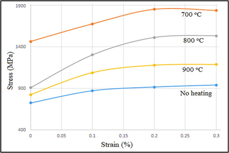
The relation between stress and strain at various post-printing heating temperatures.
Table 2 presents all the measurements repeated on the samples after heat-treatment at different temperatures. The trend is not different when the experiments are repeated. The mechanical reaction of a material to external forces within its elastic range is described by stress and strain at no heating circumstances. At 700°C, the stress–strain relation shows its maximum values at the experimentation stage. Starting from 565.02 MPa stress at 0 strain and slowly increases to 1853.57 MPa at 0.3% strain and decreases to 1683.1 MPa. On the other hand, at 800°C the stress–strain relation starts at a very low value of 17.94 MPa which then subsequently shows a rise to a maximum of 1509.72 MPa and gradually decreases to 1210.76 MPa. Moreover, at 900°C, the value of stress is 23.92 MPa at 0 strain and it also shows a gradual hike to 1189.84 MPa at a higher strain of 0.3% and then falls to a value of 914.80 MPa. Thus, for the parts printed using titanium powder, it can be concluded that at 900°C, there is a minimum variation in stress and strain. Thus, it will be subjected to more deformation at this temperature. But when not heated it shows the least deformation values. At 700°C, it shows that the particle can withstand more deformation when subjected to mechanical testing. As the temperature rises, the printed parts show less strength and are highly prone to mechanical deformation [26].
Experimental values of stress and strain at various heating temperatures
| Strain (MPa) | Stress (%), no heating | Stress (%) at 700°C | Stress (%) at 800°C | Stress (%) at 900°C |
|---|---|---|---|---|
| 0 | 47.83277 | 565.02 | 17.94 | 23.92 |
| 0 | 346.7864 | 1061.29 | 517.19 | 508.22 |
| 0 | 726.4575 | 1464.87 | 908.82 | 825.11 |
| 0.1 | 872.9448 | 1677.13 | 1303.44 | 1091.18 |
| 0.1 | 905.8297 | 1736.92 | 1431.99 | 1156.95 |
| 0.1 | 902.8402 | 1751.87 | 1452.91 | 1133.03 |
| 0.2 | 932.7355 | 1826.61 | 1467.86 | 1162.93 |
| 0.2 | 917.7878 | 1853.51 | 1512.71 | 1180.87 |
| 0.3 | 941.7041 | 1838.57 | 1533.63 | 1189.84 |
| 0.3 | 810.1645 | 1683.11 | 1509.72 | 1052.32 |
| 0.3 | 1145.79 | 1683.11 | 1210.76 | 914.8 |
4 Conclusion
Several tensile test bars were 3D printed at various tilt orientations and were subjected to post-print heat treatment. The heat-treated parts were then characterized for surface roughness, mechanical strength, and SEM microstructure analysis. The UTS and Young’s modulus, surface roughness results, and strain–stress analysis were performed for the parts printed at three tilt orientations (0°, 45°, and 90°). At 0° tilt, the UTS of the part was 1,150 MPa and shows the maximum surface roughness of 29 μm and a Young’s modulus of 116 GPa. But at 45°, the Young’s modulus reaches a maximum value of 120 GPa and the surface roughness reduces significantly to 6.5 μm. However, the 90° tilt resulted in a better mechanical strength as UTS raised to a high value of 1,200 MPa and very less surface roughness of 0.4 μm was obtained. The Young’s modulus value is also at the lowest, 112 GPa. From these results, we can conclude that the 90° print angle (vertical printing) is the best printing angle at least for printing the parts from titanium alloy with the given printing parameters. Furthermore, the stress and strain are at maximum at 700°C and the UTS and Young’s modulus values are 1,050 MPa and 112 GPa, respectively. Finally at 900°C, the UTS value is maximum, i.e., 1,070 MPa. This material deformation at a high temperature led to a decrease in the stress–strain values which reduce the UTS of the material. So, from this, it is evident that titanium alloys are best suited to be heat treated for a particular range of temperature (800°C), but when further heated, the strength of the titanium print parts decreases. When comparing these temperatures, the maximum value of Young’s modulus, which is 120 GPa, showing maximum elasticity, is obtained at 800°C . At 700°C the value is 112 GPa and shows a surge at 800°C and then when the temperature is increased further to 900°C, the Young’s modulus decreases to 110 GPa. Based on the comparison with the various literature and the experimental findings, it is evident that the stress–strain or the strain-strength relations will be positive only up to a certain limit of temperature as in the case of the titanium alloy. This limit depends on the size, shape, and other physical properties of the 3D-printed object. The titanium alloy can only hold stress up to a certain limit after which the stress reduces drastically. In agreement with other literature, we reported that the desired mechanical properties of 3D printed parts can be attained by proper adjustment of printing orientation and post-print heat treatment temperature.
Acknowledgments
Researchers Supporting Project number (RSPD2024R1060), King Saud University, Riyadh, Saudi Arabia.
-
Funding information: Researchers Supporting Project number (RSPD2024R1060), King Saud University, Riyadh, Saudi Arabia.
-
Author contributions: All authors have accepted responsibility for the entire content of this manuscript and approved its submission.
-
Conflict of interest: The authors state no conflict of interest.
References
[1] Vock S, Klöden B, Kirchner A, Weißgärber T, Kieback B. Powders for powder bed fusion: A review. Prog Addit Manuf. 2019;4:383.10.1007/s40964-019-00078-6Search in Google Scholar
[2] Michaela F, Dalibor V. Thermal treatment of 3D-printed titanium alloy. Manuf Tech. 2018;18:277.10.21062/ujep/82.2018/a/1213-2489/MT/18/2/227Search in Google Scholar
[3] Yi Z, William J, Yeon-Gil J, Jing Z. Additive manufacturing processes and equipment. Addit Manuf. 2018;1:39.10.1016/B978-0-12-812155-9.00002-5Search in Google Scholar
[4] Alexandra A, Robert F, Thomas E, Florian P. Powder metallurgy strategies to improve properties and processing of titanium alloys. Adv Energ Mat. 2017;19(6):1600743.Search in Google Scholar
[5] Slotwinski JA, Garboczi EJ, Stutzman PE, Ferraris CF, Watson SS, Peltz MA. Characterization of metal powders used for additive manufacturing. J Res Natl Inst Stand Technol. 2014;119:460.10.6028/jres.119.018Search in Google Scholar PubMed PubMed Central
[6] Altatu M, Cristiana C. Effect of heat treatment on some titanium alloys used as biomaterials. Appl Sci. 2022;12(21):11241.Search in Google Scholar
[7] Novana H, Miller WS, Ahmad Z. Effects of build orientation and heat treatment on microstructure, mechanical and corrosion properties of Al6061 aluminium parts built by cold spray additive manufacturing process. Intl J Mech Sci. 2021;204:106526.10.1016/j.ijmecsci.2021.106526Search in Google Scholar
[8] Hartunian P, Eshraghi M. Effect of build orientation on the microstructure and mechanical properties of selective laser-melted Ti-6Al-4V alloy. J Manuf Mater Proc. 2018;2(4):69.10.3390/jmmp2040069Search in Google Scholar
[9] Lin JW, Feng KY, Tekdir H, Hu JY, Zhao Z, Huang L. The effect of a novel low-temperature vacuum heat treatment on the microstructure and properties of Ti–6Al–4V alloys manufactured by selective laser melting. Vacuum. 2021;193:110554.10.1016/j.vacuum.2021.110554Search in Google Scholar
[10] Eryildiz M. Effect of build orientation on mechanical behaviour and build time of FDM 3D-printed PLA Parts: An experimental investigation. Eur Mech Sci. 2021;5:116.10.26701/ems.881254Search in Google Scholar
[11] Bermingham M, Xue A, Lin Z, Welsch G. Microstructure-gradient approach for effective determination of post-heat treatment temperature of an additive manufactured Ti-6Al-4V sample. J All Comp. 2022;921:165630.10.1016/j.jallcom.2022.165630Search in Google Scholar
[12] Zhilyaev AP, Ringot G, Huang Y, Cabrera JM, Langdon TG. Mechanical behaviour, and microstructure properties of titanium powder consolidated by high-pressure torsion. Mater Sci Eng A. 2017;688:498–504.10.1016/j.msea.2017.02.032Search in Google Scholar
[13] Mueller J, Shea K. The effect of build orientation on the mechanical properties in inkjet 3D-printing. In: Proceedings of International Solid Freeform Fabrication (SFF) Symposium 26. Austin, USA; 2015. p. 983–90.Search in Google Scholar
[14] Baltatu MS, Cristiana C. Effect of heat treatment on some titanium alloys used as biomaterials. J Mater Eng Perform. 2022;12:11241.10.3390/app122111241Search in Google Scholar
[15] Gorji NE, Robert R, Dermot B. X-ray tomography, AFM and nanoindentation measurements for recyclability analysis of 316L powders in 3D printing process. Powder Technol. 2020;47:1113.10.1016/j.promfg.2020.04.127Search in Google Scholar
[16] Alonso B, Capella W, Dorador J, Ekdale AA, Grove C, Lauridsen BW. Introducing Fiji and icy image processing techniques in iconological research as a tool for Sedimentary Basin analysis. J Microsc. 2019;413:143.10.1016/j.margeo.2019.03.013Search in Google Scholar
[17] Lind R. Open-source software for image processing and analysis: Picture this with ImageJ. Microsc Microanal. 2014;20:131.10.1533/9781908818249.131Search in Google Scholar
[18] Jayaprithika A, Mannan M, Santos R, Shafigh P, Yousif E, Adebakin I. Microstructural pore analysis using SEM and ImageJ on the absorption of treated coconut shell aggregate. Constr Build Mater. 2021;324:129217.10.1016/j.jclepro.2021.129217Search in Google Scholar
[19] Dı́ez M, Jenkins D, Flores B, Grigore M, Patrick J, Lin M. Automated procedure for Coke microstructural characterization in ImageJ software aiming industrial application. Fuel. 2021;304:121374.10.1016/j.fuel.2021.121374Search in Google Scholar
[20] Hu Y, Hanning C, Xiaohui J, Xiaodan L, Jianbo L. Heat treatment of titanium manufactured by selective laser melting: Microstructure and tensile properties. J Mat Res Tech. 2022;18:245.10.1016/j.jmrt.2022.02.106Search in Google Scholar
[21] Sharon S, Olukayode O, Eugene O, Apata O. Additive manufacturing of titanium-based alloys - a review of methods, properties, challenges, prospects. Mater Today Commun. 2022;8:e09041.10.1016/j.heliyon.2022.e09041Search in Google Scholar PubMed PubMed Central
[22] Alexandra A, Robert F, Thomas E, Florian P. Powder metallurgy strategies to improve properties and processing of Titanium alloy. Powder Metall. 2017;19:1600743.10.1002/adem.201600743Search in Google Scholar
[23] Wang D, Linqing L, Guowei D. Recent progress on additive manufacturing of multi-material structures with laser powder bed fusion. Prog Addit Manuf. 2022;13:329.10.1080/17452759.2022.2028343Search in Google Scholar
[24] Sanforda L, Jaafara I, Seibia A, Gohnb A. The effect of infill angle, build orientation, and void fraction on the tensile strength and fracture of 3D printed ASA via fused filament fabrication. Mater Lett. 2022;33:569.10.1016/j.mfglet.2022.07.070Search in Google Scholar
[25] Wang J, Guo X, Qin J, Zhang D, Lu W, Fernández A. Microstructure and mechanical properties of investment casted titanium matrix composites with B4C additions. Mat Sci Eng A. 2015;628:366.10.1016/j.msea.2015.01.067Search in Google Scholar
[26] Kang N, Coddet P, Liao H, Coddet C. The effect of heat treatment on microstructure and tensile properties of cold spray Zr base metal glass/Cu composite. Surf Coat Tech. 2015;280:64.10.1016/j.surfcoat.2015.08.061Search in Google Scholar
© 2023 the author(s), published by De Gruyter
This work is licensed under the Creative Commons Attribution 4.0 International License.
Articles in the same Issue
- Regular Articles
- Dynamic properties of the attachment oscillator arising in the nanophysics
- Parametric simulation of stagnation point flow of motile microorganism hybrid nanofluid across a circular cylinder with sinusoidal radius
- Fractal-fractional advection–diffusion–reaction equations by Ritz approximation approach
- Behaviour and onset of low-dimensional chaos with a periodically varying loss in single-mode homogeneously broadened laser
- Ammonia gas-sensing behavior of uniform nanostructured PPy film prepared by simple-straightforward in situ chemical vapor oxidation
- Analysis of the working mechanism and detection sensitivity of a flash detector
- Flat and bent branes with inner structure in two-field mimetic gravity
- Heat transfer analysis of the MHD stagnation-point flow of third-grade fluid over a porous sheet with thermal radiation effect: An algorithmic approach
- Weighted survival functional entropy and its properties
- Bioconvection effect in the Carreau nanofluid with Cattaneo–Christov heat flux using stagnation point flow in the entropy generation: Micromachines level study
- Study on the impulse mechanism of optical films formed by laser plasma shock waves
- Analysis of sweeping jet and film composite cooling using the decoupled model
- Research on the influence of trapezoidal magnetization of bonded magnetic ring on cogging torque
- Tripartite entanglement and entanglement transfer in a hybrid cavity magnomechanical system
- Compounded Bell-G class of statistical models with applications to COVID-19 and actuarial data
- Degradation of Vibrio cholerae from drinking water by the underwater capillary discharge
- Multiple Lie symmetry solutions for effects of viscous on magnetohydrodynamic flow and heat transfer in non-Newtonian thin film
- Thermal characterization of heat source (sink) on hybridized (Cu–Ag/EG) nanofluid flow via solid stretchable sheet
- Optimizing condition monitoring of ball bearings: An integrated approach using decision tree and extreme learning machine for effective decision-making
- Study on the inter-porosity transfer rate and producing degree of matrix in fractured-porous gas reservoirs
- Interstellar radiation as a Maxwell field: Improved numerical scheme and application to the spectral energy density
- Numerical study of hybridized Williamson nanofluid flow with TC4 and Nichrome over an extending surface
- Controlling the physical field using the shape function technique
- Significance of heat and mass transport in peristaltic flow of Jeffrey material subject to chemical reaction and radiation phenomenon through a tapered channel
- Complex dynamics of a sub-quadratic Lorenz-like system
- Stability control in a helicoidal spin–orbit-coupled open Bose–Bose mixture
- Research on WPD and DBSCAN-L-ISOMAP for circuit fault feature extraction
- Simulation for formation process of atomic orbitals by the finite difference time domain method based on the eight-element Dirac equation
- A modified power-law model: Properties, estimation, and applications
- Bayesian and non-Bayesian estimation of dynamic cumulative residual Tsallis entropy for moment exponential distribution under progressive censored type II
- Computational analysis and biomechanical study of Oldroyd-B fluid with homogeneous and heterogeneous reactions through a vertical non-uniform channel
- Predictability of machine learning framework in cross-section data
- Chaotic characteristics and mixing performance of pseudoplastic fluids in a stirred tank
- Isomorphic shut form valuation for quantum field theory and biological population models
- Vibration sensitivity minimization of an ultra-stable optical reference cavity based on orthogonal experimental design
- Effect of dysprosium on the radiation-shielding features of SiO2–PbO–B2O3 glasses
- Asymptotic formulations of anti-plane problems in pre-stressed compressible elastic laminates
- A study on soliton, lump solutions to a generalized (3+1)-dimensional Hirota--Satsuma--Ito equation
- Tangential electrostatic field at metal surfaces
- Bioconvective gyrotactic microorganisms in third-grade nanofluid flow over a Riga surface with stratification: An approach to entropy minimization
- Infrared spectroscopy for ageing assessment of insulating oils via dielectric loss factor and interfacial tension
- Influence of cationic surfactants on the growth of gypsum crystals
- Study on instability mechanism of KCl/PHPA drilling waste fluid
- Analytical solutions of the extended Kadomtsev–Petviashvili equation in nonlinear media
- A novel compact highly sensitive non-invasive microwave antenna sensor for blood glucose monitoring
- Inspection of Couette and pressure-driven Poiseuille entropy-optimized dissipated flow in a suction/injection horizontal channel: Analytical solutions
- Conserved vectors and solutions of the two-dimensional potential KP equation
- The reciprocal linear effect, a new optical effect of the Sagnac type
- Optimal interatomic potentials using modified method of least squares: Optimal form of interatomic potentials
- The soliton solutions for stochastic Calogero–Bogoyavlenskii Schiff equation in plasma physics/fluid mechanics
- Research on absolute ranging technology of resampling phase comparison method based on FMCW
- Analysis of Cu and Zn contents in aluminum alloys by femtosecond laser-ablation spark-induced breakdown spectroscopy
- Nonsequential double ionization channels control of CO2 molecules with counter-rotating two-color circularly polarized laser field by laser wavelength
- Fractional-order modeling: Analysis of foam drainage and Fisher's equations
- Thermo-solutal Marangoni convective Darcy-Forchheimer bio-hybrid nanofluid flow over a permeable disk with activation energy: Analysis of interfacial nanolayer thickness
- Investigation on topology-optimized compressor piston by metal additive manufacturing technique: Analytical and numeric computational modeling using finite element analysis in ANSYS
- Breast cancer segmentation using a hybrid AttendSeg architecture combined with a gravitational clustering optimization algorithm using mathematical modelling
- On the localized and periodic solutions to the time-fractional Klein-Gordan equations: Optimal additive function method and new iterative method
- 3D thin-film nanofluid flow with heat transfer on an inclined disc by using HWCM
- Numerical study of static pressure on the sonochemistry characteristics of the gas bubble under acoustic excitation
- Optimal auxiliary function method for analyzing nonlinear system of coupled Schrödinger–KdV equation with Caputo operator
- Analysis of magnetized micropolar fluid subjected to generalized heat-mass transfer theories
- Does the Mott problem extend to Geiger counters?
- Stability analysis, phase plane analysis, and isolated soliton solution to the LGH equation in mathematical physics
- Effects of Joule heating and reaction mechanisms on couple stress fluid flow with peristalsis in the presence of a porous material through an inclined channel
- Bayesian and E-Bayesian estimation based on constant-stress partially accelerated life testing for inverted Topp–Leone distribution
- Dynamical and physical characteristics of soliton solutions to the (2+1)-dimensional Konopelchenko–Dubrovsky system
- Study of fractional variable order COVID-19 environmental transformation model
- Sisko nanofluid flow through exponential stretching sheet with swimming of motile gyrotactic microorganisms: An application to nanoengineering
- Influence of the regularization scheme in the QCD phase diagram in the PNJL model
- Fixed-point theory and numerical analysis of an epidemic model with fractional calculus: Exploring dynamical behavior
- Computational analysis of reconstructing current and sag of three-phase overhead line based on the TMR sensor array
- Investigation of tripled sine-Gordon equation: Localized modes in multi-stacked long Josephson junctions
- High-sensitivity on-chip temperature sensor based on cascaded microring resonators
- Pathological study on uncertain numbers and proposed solutions for discrete fuzzy fractional order calculus
- Bifurcation, chaotic behavior, and traveling wave solution of stochastic coupled Konno–Oono equation with multiplicative noise in the Stratonovich sense
- Thermal radiation and heat generation on three-dimensional Casson fluid motion via porous stretching surface with variable thermal conductivity
- Numerical simulation and analysis of Airy's-type equation
- A homotopy perturbation method with Elzaki transformation for solving the fractional Biswas–Milovic model
- Heat transfer performance of magnetohydrodynamic multiphase nanofluid flow of Cu–Al2O3/H2O over a stretching cylinder
- ΛCDM and the principle of equivalence
- Axisymmetric stagnation-point flow of non-Newtonian nanomaterial and heat transport over a lubricated surface: Hybrid homotopy analysis method simulations
- HAM simulation for bioconvective magnetohydrodynamic flow of Walters-B fluid containing nanoparticles and microorganisms past a stretching sheet with velocity slip and convective conditions
- Coupled heat and mass transfer mathematical study for lubricated non-Newtonian nanomaterial conveying oblique stagnation point flow: A comparison of viscous and viscoelastic nanofluid model
- Power Topp–Leone exponential negative family of distributions with numerical illustrations to engineering and biological data
- Extracting solitary solutions of the nonlinear Kaup–Kupershmidt (KK) equation by analytical method
- A case study on the environmental and economic impact of photovoltaic systems in wastewater treatment plants
- Application of IoT network for marine wildlife surveillance
- Non-similar modeling and numerical simulations of microploar hybrid nanofluid adjacent to isothermal sphere
- Joint optimization of two-dimensional warranty period and maintenance strategy considering availability and cost constraints
- Numerical investigation of the flow characteristics involving dissipation and slip effects in a convectively nanofluid within a porous medium
- Spectral uncertainty analysis of grassland and its camouflage materials based on land-based hyperspectral images
- Application of low-altitude wind shear recognition algorithm and laser wind radar in aviation meteorological services
- Investigation of different structures of screw extruders on the flow in direct ink writing SiC slurry based on LBM
- Harmonic current suppression method of virtual DC motor based on fuzzy sliding mode
- Micropolar flow and heat transfer within a permeable channel using the successive linearization method
- Different lump k-soliton solutions to (2+1)-dimensional KdV system using Hirota binary Bell polynomials
- Investigation of nanomaterials in flow of non-Newtonian liquid toward a stretchable surface
- Weak beat frequency extraction method for photon Doppler signal with low signal-to-noise ratio
- Electrokinetic energy conversion of nanofluids in porous microtubes with Green’s function
- Examining the role of activation energy and convective boundary conditions in nanofluid behavior of Couette-Poiseuille flow
- Review Article
- Effects of stretching on phase transformation of PVDF and its copolymers: A review
- Special Issue on Transport phenomena and thermal analysis in micro/nano-scale structure surfaces - Part IV
- Prediction and monitoring model for farmland environmental system using soil sensor and neural network algorithm
- Special Issue on Advanced Topics on the Modelling and Assessment of Complicated Physical Phenomena - Part III
- Some standard and nonstandard finite difference schemes for a reaction–diffusion–chemotaxis model
- Special Issue on Advanced Energy Materials - Part II
- Rapid productivity prediction method for frac hits affected wells based on gas reservoir numerical simulation and probability method
- Special Issue on Novel Numerical and Analytical Techniques for Fractional Nonlinear Schrodinger Type - Part III
- Adomian decomposition method for solution of fourteenth order boundary value problems
- New soliton solutions of modified (3+1)-D Wazwaz–Benjamin–Bona–Mahony and (2+1)-D cubic Klein–Gordon equations using first integral method
- On traveling wave solutions to Manakov model with variable coefficients
- Rational approximation for solving Fredholm integro-differential equations by new algorithm
- Special Issue on Predicting pattern alterations in nature - Part I
- Modeling the monkeypox infection using the Mittag–Leffler kernel
- Spectral analysis of variable-order multi-terms fractional differential equations
- Special Issue on Nanomaterial utilization and structural optimization - Part I
- Heat treatment and tensile test of 3D-printed parts manufactured at different build orientations