Investigation of different structures of screw extruders on the flow in direct ink writing SiC slurry based on LBM
-
 ,
,

Abstract
Direct ink writing provides a new method for ceramic material forming. The single-screw extruder is used here to extrude viscous SiC slurry. Because the flow mechanism of ceramic slurry in the slurry direct writing extrusion device is unclear, lattice Boltzmann method (LBM) is used to analyze the flow process of ceramic slurry in the extrusion device. In this study, three different types of special-shaped, single-screw extruders (constant depth variable pitch screw, variable depth constant pitch screw, and variable depth variable pitch screw) are investigated to explore the effects of the shapes on the flow process. Compared with the traditional single-screw extruder, more attention should be paid to the difference in the flow channel. The non-Newtonian rheological model of SiC slurry is built, then the LBM for the non-Newtonian slurry is introduced and used to conduct the simulations based on the aforementioned three different cases. The results show that the effect of constant depth and variable pitch screw on the flow of ceramic slurry is the least and the flow of ceramic slurry in variable depth and variable pitch screw is the most complex.
Nomenclature
- D Ⅱ
-
the second variable of the strain rate tensor
- e a
-
discrete speed of the D2Q9 model
-
-
equilibrium distribution function
- r
-
position vector
- S αβ
-
strain rate tensor
- u
-
velocity vector
- w a
-
weight factor
- ρ
-
density
- τ
-
relaxation time
- μ
-
dynamic viscosity
- δr
-
space displacement
- δt
-
time displacement
- ω
-
collision frequency
1 Introduction
Ceramic materials have many advantages, such as high melting point, high hardness, good wear resistance, and chemical stability, which have been widely used in aerospace, electronic manufacturing, biomedical, and other fields [1,2]. There are many processing methods for molding ceramic parts. Injection molding is the most traditional processing method. When it is used to process a workpiece with complex geometry, the complex process and long processing cycle are required and the molding will fail [3]. As a new technology of intelligent manufacturing, additive manufacturing (AM) provides a new way of processing the ceramic parts [4,5,6,7,8]. Direct ink writing (DIW) is an extrusion method of AM, which has been one of the mainstream processes for molding ceramic materials by AM technologies in recent years. It can realize complex ceramic parts with complex geometries [9,10,11,12,13,14,15].
Generally speaking, DIW requires good material fluidity, but the viscosity of the ceramic slurry is relatively high, and traditional equipment (needle-cylinder device) cannot effectively transport it. Therefore, a single-screw extruder is used here to improve transportation performance [16]. The depth and pitch screw are the main structural parameters. To understand the effect of two parameters on the ceramic flow, three different types of special-shaped, single-screw extruders (constant depth variable pitch screw, variable depth constant pitch screw, and variable depth variable pitch screw) [17,18,19] are analyzed, respectively [20].
To conduct the flow analysis, many common methods can be adopted, such as experiments and numerical simulation. For the experiment method, a sensor is used to install on the extruder. It is difficult to find an appropriate sensor with good wet-skid corrosion and impact resistance. Therefore, the experimental method is not recommended here. Numerical simulation has become a more suitable alternative method. When the problems of fluid mechanics cannot be solved by existing theories, the finite element method and the finite difference method have helped solve a lot of practical problems. Lattice Boltzmann method (LBM) is a fluid calculation and modeling method different from traditional numerical methods, which is a simple algorithm, easy programming, has high parallelism, and can handle complex boundary conditions. Therefore, the LBM based on MATLAB programming is used here to analyze the ceramic slurry flow. LBM can process not only the simple flow but also the complex situation, such as the complex rheological behavior. David et al. [21] made an impedance model of human arterial blood flow using MATLAB. Ponalagusamy and Manchi [22] conducted a flow analysis of non-Newtonian fluid in arteries with mild stenosis. Siddiqa et al. [23] analyzed the power-law flow in a narrow tube by LBM. Bouzit et al. [24] studied the rheological characteristics and curvature radius effect of non-Newtonian fluid flow in a curved square pipe. Bisht and Patil [25] evaluated the applicability of the MRT LBM for ordinary non-Newtonian fluids and conducted the relevant case validation. Khabazi et al. [26] used MRT LBM to simulate and analyze the Bingham fluid inside a two-dimensional channel and considered several factors that could affect the flow. Based on the aforementioned cases, LBM can also be used to analyze non-Newtonian ceramic flow in the single-screw extruder.
The main objective of this study is to analyze the differences in flow during slurry transportation between three types of special-shaped single screws and traditional single-screw extruders. A LBM suitable for non-Newtonian fluids such as ceramic slurry is proposed and used for simulation analysis. Finally, the simulation results of the three were compared for analysis and discussion.
This article is organized as follows. In Section 2, the rheological model is built by testing the rheological behavior of ceramic slurry. In Section 3, the LBM for non-Newtonian ceramic slurry flow is proposed. In Section 4, the numerical results are obtained by analyzing the flow in three different types of profiled single-screw extruders. Finally, the simulation results are discussed and concluded.
2 Rheological behaviors
2.1 Preparation of ceramic slurry
Raw materials contained an average particle size of 0.5 μm, 60 wt% SiC powders, 20 wt% carbon powder with an average particle size of 250 nm, 5 wt% polyvinyl alcohol, and 20 wt% water. First, polyvinyl alcohol and water were mixed to prepare the adhesive solution. Then, the ceramic powder and carbon powder were added into the adhesive solution and centrifuged at 1,000 rpm for 3 minutes to completely dissolve them. Finally, the ceramic slurry with a solid content of 80% was obtained for subsequent experiments [27,28,29].
2.2 Rheological test and result
Based on the rheological test result, the Williamson model and the Sisko model are considered the most possible models for the slurry. In Figure 1, the comparison is made between the Williamson model, the Sisko model, and the actual measured data.

Nonlinear fitting results.
It can be found that the fitting curve coincidence between the Williamson model [30] and the measured data is higher than that of the Sisko model [31]. Table 1 shows the specific equations and parameters of the Williamson model and the Sisko model. The R-square can indicate the quality of the fitting result. The closer it is to 1, the better the fitting result is. Therefore, the Williamson model is more suitable for the following simulation.
Fitting results of different flow models
| Model | Equation | R-square | Adjusted R-square |
|---|---|---|---|
| Williamson |
|
0.999 | 0.9989 |
| Sisko |
|
0.9125 | 0.9060 |
3 LBM for non-newtonian SiC slurry flow
A complete lattice Boltzmann model generally consists of three parts: discrete velocity model, equilibrium distribution function, and evolution equation of distribution function.
The discrete speed of the D2Q9 model [32,33] can be expressed as:
where
Under the condition of a stationary boundary, a standard reflection form was adopted. When the boundary velocity has been determined, Zou and He [34] proposed a new non-equilibrium-state reflection form as a new boundary treatment method, which does not require the boundary to be determined as a solid boundary.
The evolution equation of the discrete distribution function in the D2Q9 model is as follows:
where ω is the collision frequency,
The formula for the relaxation parameter ω is as follows:
where τ is the relaxation time, μ is the dynamic viscosity, and ρ is the density.
For D2Q9 model, the sound velocity of the lattice
In the D2Q9 model, the equilibrium distribution function can be expressed as:
where
When
To recover the macro equation, the equilibrium distribution function needs to satisfy the following equations:
For the non-Newtonian fluid, its shear rate changes with viscosity, and its relaxation time also changes. Therefore, the strain rate tensor shall be derived as:
The second variable of the strain rate tensor can be calculated by the following equation:
The shear rate is derived from the following equation:
The rheological equation of the Williamson model is expressed as:
Based on Eqs. (10) and (11), the dynamic viscosity can be obtained, and then, the next iteration can be conducted.
MATLAB software is used here for numerical simulation, and the specific steps are as follows:
Units shall be converted according to the Reynolds number. Then, the specific physical quantities are transformed into dimensionless numbers for numerical simulation. Define the initial calculation parameters, such as lattice number, entrance velocity, initial relaxation parameter, and initial density.
Set the initial distribution function and the equilibrium distribution function. Initially, the distribution function is the same as the equilibrium distribution function, and its expression is shown in Eq. (5).
Due to the simulation of the special-shaped, single-screw extruder, the flow channel should be designed according to different types of screws.
In each step, the calculation using lattice Boltzmann requires two parts, namely, the collision process and the migration process. The LBGK approximate equation is selected for the design program, so the collision equation is as follows:
(12)The migration equation is as follows:
(13)According to Eq. (11), the dynamic viscosity of the ceramic slurry is constantly changing because it belongs to non-Newtonian fluids, and new viscosity and relaxation parameters need to be calculated for the next iteration.
Conduct non-equilibrium bound boundary treatment.
Generate a mobile cloud image through the function of the image.
4 Effect of different-shaped single screw on ceramic slurry flow
In the current work, three types of special-shaped single screws have been considered: constant depth variable pitch screw, variable depth constant pitch screw, and variable depth variable pitch screw. The aim is to find the effect of two parameters (depth and pitch screw) on the ceramic flow in DIW technology.
4.1 Constant depth variable pitch screw
When a constant depth variable pitch screw is used, it is not necessary to consider the depth change compared with the traditional screw extruder. The flow channel of the screw can be considered an isosceles trapezoid on the x–z-section. The structure and the flow channel are shown in Figures 2 and 3. The width of the channel inlet is 10 mm, and the x–y-section at z = 5 mm is taken for analysis, while the y–z-section at x = 50 mm is taken for analysis. The flow in both the x–y- and y–z-sections is analyzed with a constant. In the simulation, the involved parameters are set as follows. The grid point is set to 200 × 50. When the difference in the velocities of two adjacent iterations is smaller than 10−6, the simulation is finished. The same conditions are adopted in the following situations.

Engineering drawing of constant depth variable pitch screw.

Flow channel of constant depth variable pitch screw.
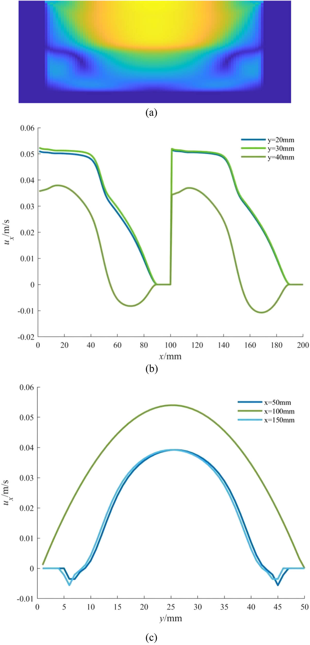
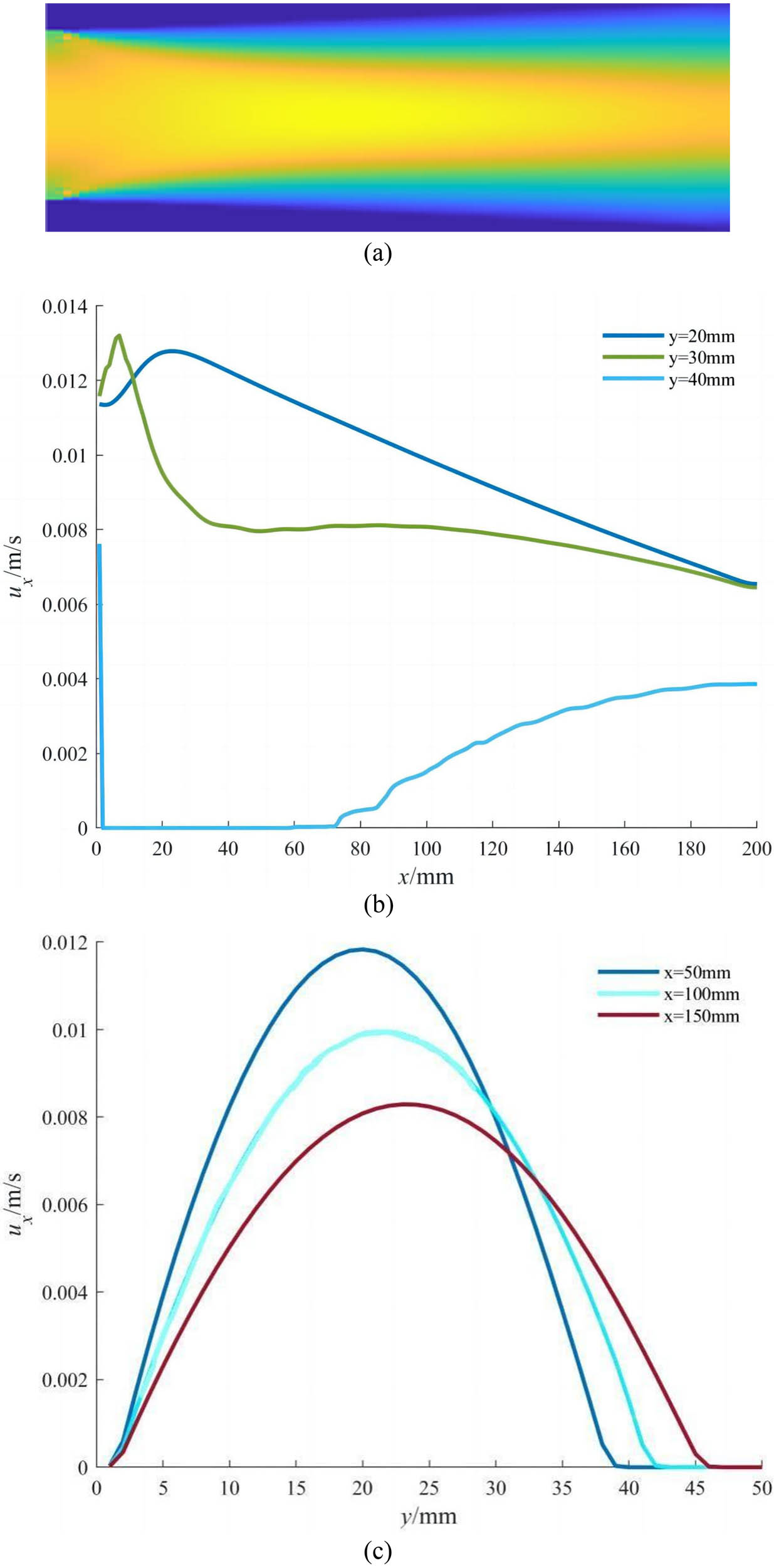
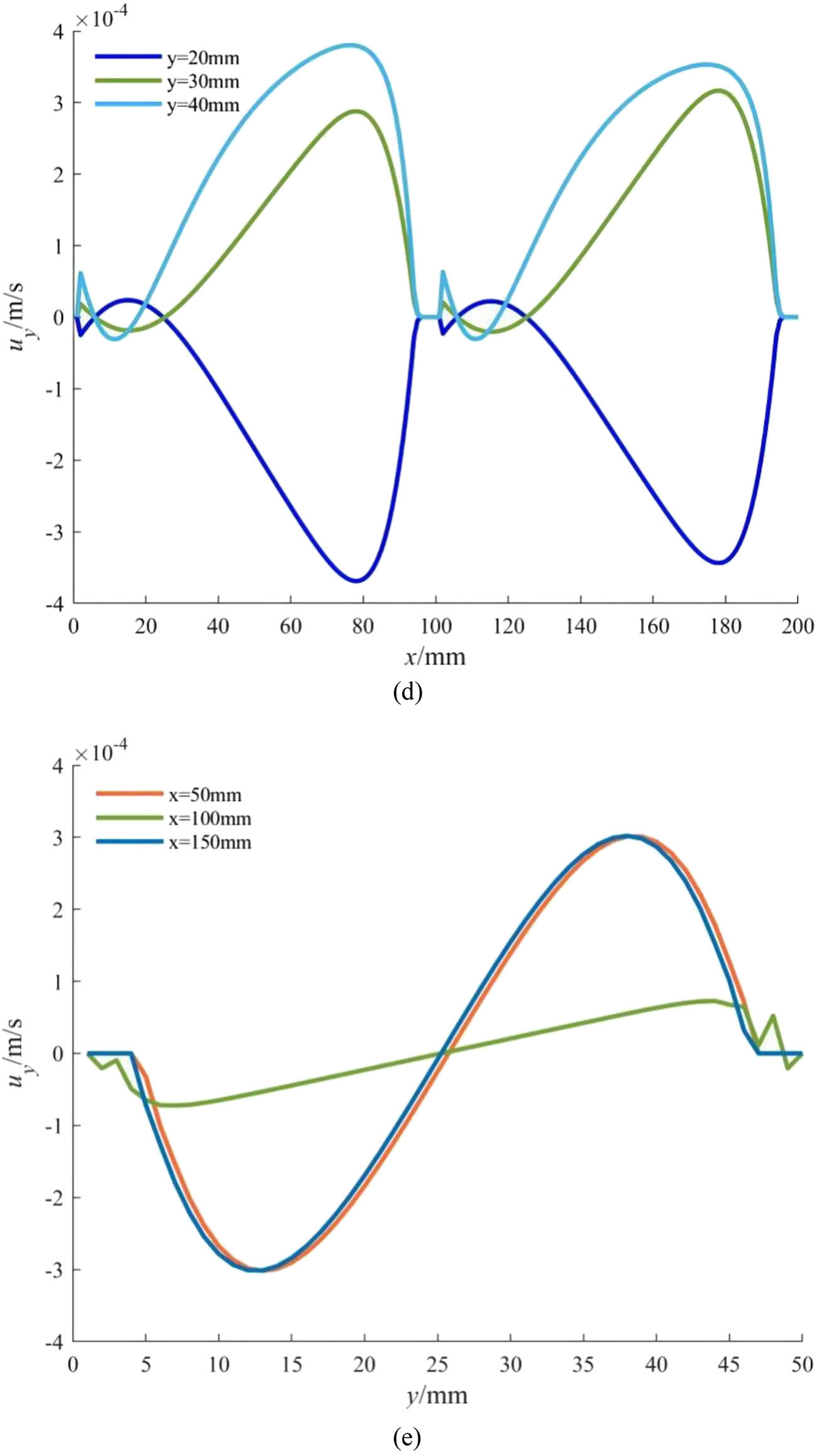
When simulating the flow in the x–y-section, the inlet velocity is represented by a parabola, with a maximum value of 0.5 m/s and a minimum value of 0 m/s, the entrance speed here is set based on the actual situation, and the same conditions are adopted in the following situations. The cloud diagram is shown in Figure 4(a); the orange represents the high-velocity area, and the blue corresponds to the low-velocity area. As shown in Figure 4(b) and (c), the velocity u x in the x-direction shows a trend of first increasing and then slowly decreasing, the reason for the appearance of this pattern is probably due to the gradually expanding opening of the flow channel, but due to the small initial diameter, it has an impact on the flow. While the velocity curve in the y-direction shows a parabolic shape with an opening downward. As shown in Figure 4(d) and (e), the velocity u y in the x-direction shows a trend of first increasing, then decreasing, and finally slowly increasing. The velocity u y in the y-direction first decreases and then increases, remaining unchanged at a velocity of 0 and finally showing an upward trend.


Simulation results of constant depth variable pitch screw in the x–y-direction: (a) velocity distribution diagram of a constant depth variable pitch screw, (b) velocity distribution of u x in the x-direction, (c) velocity distribution of u x in the y-direction, (d) velocity distribution of u y in the x-direction, and (e) velocity distribution of u y in the y-direction.
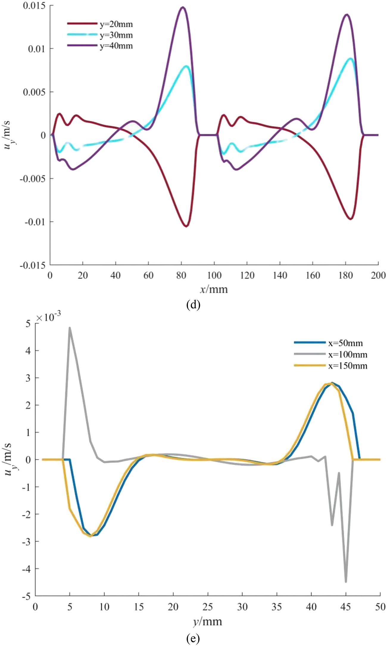
When the flow in the y–z-section is investigated, the inlet velocity is represented by a parabola, with a maximum value of 0.2 m/s and a minimum value of 0 m/s. The value of the inlet velocity here is selected based on the simulation results in the x–y-section. The cloud diagram is shown in Figure 5(a). The velocity u
x
in the x-direction shown in Figure 5(b) presents a similar “N”-shaped change trend, i.e., it first linearly decreases, then suddenly rises, and finally linearly decreases. The graph exhibits identical trends in the two intervals x = 0–100 mm and x = 100–200 mm, as shown in Figure 5(c). It is speculated that the reason for this situation may be due to the overall symmetry of the flow channel. The velocity change trend in the y-direction presents a parabolic shape with an opening downward. As shown in Figure 5(d) and (e), the velocity u
y
in the x-direction and the upper half of the flow channel first decreases, then rises and decreases, and finally rises; the variation pattern of the graphics here is the same as that of u
x
. The overall velocity in the y-direction shows a trend of first decreasing, then rising, and finally decreasing. The graph is symmetric about the point (y = 25 mm,


Simulation results of constant depth variable pitch screw in the y–z-direction: (a) velocity distribution diagram of a constant depth variable pitch screw, (b) velocity distribution of u x in the x-direction, (c) velocity distribution of u x in the y-direction, (d) velocity distribution of u y in the x-direction, and (e) velocity distribution of u y in the y-direction.
In summary, due to the relatively regular shape of the expanded flow channel of the constant depth variable pitch screw, the impact on the flow of ceramic slurry is not significant and generally presents a form similar to Poiseuille flow.
4.2 Variable depth constant pitch screw
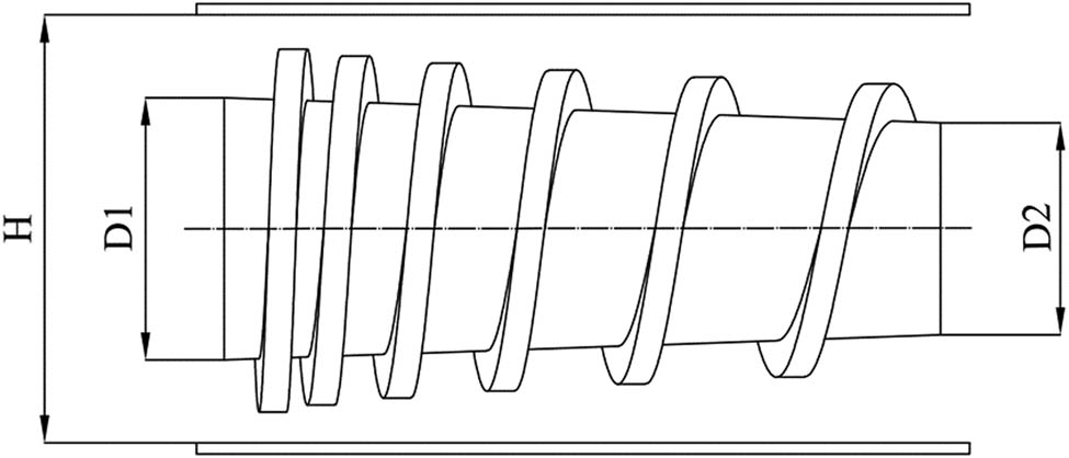
When using a variable depth constant pitch screw, it is not necessary to consider changes in pitch. The structure and the flow channel are shown in Figures 6 and 7. The flow channel of the screw is rectangular in the x–z-section. Similar to the constant depth variable pitch screw, the flow in two different cross sections will be analyzed to understand the flow mechanism.

Engineering drawing of variable depth constant pitch screw.

Flow channel of variable depth constant pitch screw.
When analyzing the flow in the x–y-section with the variable depth constant pitch screw, the inlet velocity is represented as the same as the case in Section 4.1. The cloud diagram is shown in Figure 8(a). It is found that the irregularity of the flow channel has a significant impact on the flow of ceramic paste. As shown in Figure 8(b) and (c), when u x in the x-direction is involved, the velocity curve shows a trend of first rising and then falling, but in the final part, it only shows an upward trend. The overall velocity change trend in the y-direction is similar to a parabola with an opening downward. As shown in Figure 8(d), u y in the x-direction tends to decrease first and then increase before y = 40 mm and finally tends to stabilize. However, after y = 40 mm, a maximum value will be generated and then quickly recovers to around 0. In the y-direction, it will first rise, then remain at 0, and then a peak will appear. As can be seen from Figure 8(e), the position of the peak will be delayed as the distance increases.

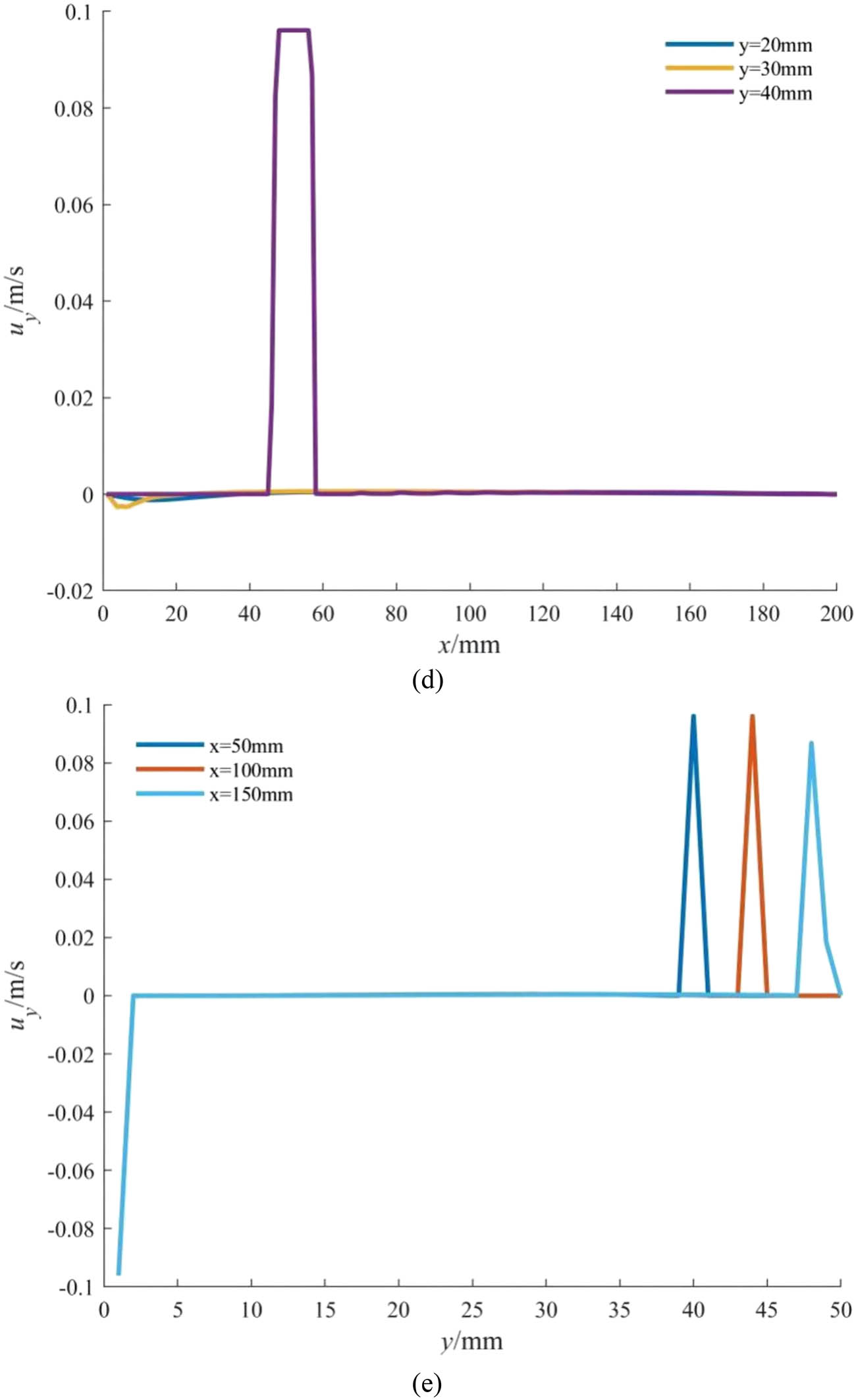
Simulation results of variable depth constant pitch screw in the x–y-direction: (a) velocity program of variable depth constant pitch screw, (b) velocity distribution of u x in the x-direction, (c) velocity distribution of u x in the y-direction, (d) velocity distribution of u y in the x-direction, and (e) velocity distribution of u y in the y-direction.
When analyzing the flow in the y–z-section with the variable depth constant pitch screw, the inlet velocity is represented by a parabola, with a maximum velocity of 1.5 m/s and a minimum velocity of 0 m/s. The value of the inlet velocity here is also selected based on the simulation results in the x–y-section. The cloud diagram is shown in Figure 9(a). The velocity component u x in the x-direction shown in Figure 9(b) presents a trend of first decreasing, then rapidly rising, and finally decreasing, and u x in the y-direction shown in Figure 9(c) presents a parabolic shape with an opening downward. As shown in Figure 9(d), u y in the x-direction is divided into two parts. In the first half of the flow channel, the change presents a trend of first falling and then rising, then falling, and then rising again. Then, repeat the previous change pattern at x = 100 mm. In the y-direction shown in Figure 9(e), it first decreases and then rises, then fluctuates up and down at 0, and then an opposite change occurred after y = 25 mm compared to before.
Simulation results of variable depth constant pitch screw in the y–z-direction: (a) velocity program of variable depth constant pitch screw, (b) velocity distribution of u x in the x-direction, (c) velocity distribution of u x in the y-direction, (d) velocity distribution of u y in the x-direction, and (e) velocity distribution of u y in the y-direction.
Compared with the constant depth variable pitch screw, the flow channel of the variable depth constant pitch screw has a greater impact on the flow of ceramic slurry. This is due to the adverse effect of the internal shape of the flow channel of this screw on the flow. In summary, the flow path of the variable depth constant pitch screw has a certain impact on the flow of ceramic slurry. The slope of the lower surface of the flow channel has some adverse effects on the flow of slurry.
4.3 Variable depth variable pitch screw
When using a variable depth variable pitch screw, both the depth and pitch are changing, which is more complex than in the aforementioned situation. The structure and the flow channel are shown in Figures 10 and 11. The flow channel of the screw is an isosceles trapezoid in the x–z-section, similar to the constant depth variable pitch screw. Similar to the first two types of screws, the flow channel should be divided into x–y- and y–z-sections.
Engineering drawing of variable depth variable pitch screw.

Flow channel of variable depth variable pitch screw.
When analyzing the flow in the x–y-section of the variable depth variable pitch screw, the inlet velocity is set as the same in the aforementioned two cases. The cloud diagram is shown in Figure 12(a). From this figure, it can be seen that the high-velocity area is significantly compressed. As can be seen from Figure 12(b)–(e), the variation trend of u x and u y is similar to and slightly different from the x–y-section of the variable depth constant pitch screw, so the variation rule of its velocity curve will not be described in more detail.

Simulation results of variable depth variable pitch screw in the x–y-direction: (a) velocity program of variable depth variable pitch screw, (b) velocity distribution of u x in the x-direction, (c) velocity distribution of u x in the y-direction, (d) velocity distribution of u y in the x-direction, and (e) velocity distribution of u y in the y-direction.
When analyzing the flow in the y–z-section with the variable depth variable pitch screw flow channel, the inlet velocity is represented by a parabola, with a maximum velocity of 0.2 m/s and a minimum velocity of 0 m/s. The value of the inlet velocity here is determined based on the aforementioned simulation results. The cloud diagram is shown in Figure 13(a). From this figure, it can be seen that the flow channel in this case has a slight impact on the flow of ceramic slurry, and it is not significant for the compression of the notification area. As can be seen from Figure 13(b)–(e), the variation trends of u x and u y are similar to and slightly different from the y–z-section of the constant depth variable pitch screw, so we will not expand on them in detail here.

Simulation results of variable depth variable pitch screw in y–z-direction: (a) velocity program of variable depth variable pitch screw, (b) velocity distribution of u x in the x-direction, (c) velocity distribution of u x in the y-direction, (d) velocity distribution of u y in the x-direction, and (e) velocity distribution of u y in the y-direction.
Compared with the two types of screws mentioned earlier, the variable depth variable pitch screw has a significant impact on the flow of ceramic slurry. This is because the internal structure of the flow channel of the variable depth variable pitch screw is much more complex than the first two, and the adverse effects on the flow are also significant. In summary, the influence of the flow channel of the variable depth variable pitch screw on the ceramic paste is the most significant among the three types of screws.
5 Discussion
This article studies the simulation analysis of ceramic slurry flow after three types of special-shaped screw flow channels are, respectively, expanded in the x–y-section and y–z-section.
First, the flow analysis results on the x–y section of three cases are compared. According to Figures 4, 8, and 12, we can see from its cloud map that the high-velocity area of the variable depth variable pitch screw flow channel accounts for the smallest proportion. In other words, this flow channel has the most significant impact on slurry flow. However, the impact of the other two screw flow channels on slurry flow is not significantly different.
Next, we will compare and discuss the simulation results of the y–z-section. According to Figures 5, 9, and 13, We can see that in this case, the high-velocity area of the variable depth constant pitch screw channel is the smallest, which means that this screw has the most significant impact on the slurry flow on the y–z-section. Then, take a look at the constant depth variable pitch screw, whose speed changes are the most regular and traceable. The speed change of the variable depth variable pitch screw is similar to the former.
6 Conclusion
As an AM technology, slurry DIW provides an innovative and effective method for ceramic material forming. To promote the transportation of slurry, a single-screw extruder is selected. The flow channel will change correspondingly when the profiled single-screw extruder is used, which will affect the normal flow and the outlet velocity distribution. In this study, three kinds of profiled single-screw extruders were taken as examples to reveal the basic mechanism of the flow channel obstacles in the profiled single-screw extruders. The LBM is an effective mesoscopic flow analysis method. To improve the stability of non-Newtonian slurry, an LBM for non-Newtonian fluid is proposed.
Based on the obtained velocity program and the speed distribution diagram on the x–y/y–z-section, the following conclusions can be summarized, which help select a suitable profiled single-screw extruder.
Combining the flow analysis diagrams of three types of screws, it can be seen that the influence of variable depth variable pitch screw on the flow of ceramic slurry is relatively complex, with more changes in the flow direction. The influence of constant depth variable pitch screw on the flow of ceramic slurry is relatively small, and overall, it shows a trend of Poisson flow.
In summary, to ensure the stability of the slurry transportation process, variable depth variable pitch screws should be avoided as much as possible for the transportation of ceramic slurry.
This article overlooks the occurrence of obstacles in the flow channel. In future work, further research will be conducted on the impact of obstacles generated in the flow channel on the flow of ceramic slurry.
Acknowledgments
This work was supported by Postgraduate Practice Innovation Program of Jiangsu Province (Grant No. SJCX22_1722) and Natural Science Foundation of the Jiangsu Higher Education Institutions of China (Grant No. 22KJB460040).
-
Funding information: This workwas supported by Postgraduate Practice Innovation Program of Jiangsu Province (Grant No. SJCX22_1722) and Natural Science Foundation of the Jiangsu Higher Education Institutions of China (Grant No. 22KJB460040).
-
Author contributions: Xu Deng and Weiwei Wu performed the simulations and finished the writing. Shuang Ding reviewed the manuscript. Yanjun Zhang validated the results. Binquan Shi conducted the investigation. The authors applied the SDC approach for the sequence of authors. All authors have accepted responsibilityfor the entire content of thismanuscript and approved its submission.
-
Conflict of interest: The authors state no conflict of interest.
-
Data availability statement: Data sharing is not applicable to this article as no datasets were generated or analysed during the current study.
Reference
[1] Soliman M, Alzahrani G, Alabdualataif F, Eldwakhly E, Alsamady S, Aldegheishem A, et al. Impact of ceramic material and preparation design on marginal fit of endocrown restorations. Materials. 2022;15(16):5592.10.3390/ma15165592Search in Google Scholar PubMed PubMed Central
[2] Mohr-Weidenfeller L, Kleinholz C, Müller B, Gropp S, Günther-Müller S, Fischer M, et al. Thermal analysis of the ceramic material and evaluation of the bonding behavior of silicon-ceramic composite substrates. J Micromech Microeng. 2022;32(10):105004.10.1088/1361-6439/ac8686Search in Google Scholar
[3] Mamatha S, Biswas P, Das D, Johnson R. Fabrication of complex shaped ceramic articles from 3D printed polylactic acid templates by replication process. Ceram Int. 2019;45(15):19577–80.10.1016/j.ceramint.2019.06.203Search in Google Scholar
[4] Wei HL, Bhadeshia HKDH, David SA, DebRoy T. Harnessing the scientific synergy of welding and additive manufacturing. Sci Technol Weld Join. 2019;24(5):361–6.10.1080/13621718.2019.1615189Search in Google Scholar
[5] Brunello G, Donos N, Sivolella S, Zavan B. Editorial: Advances in additive manufacturing technologies for the production of tissue-engineered bone scaffolds for dental applications. Front Bioeng Biotech. 2022;10:980430.10.3389/fbioe.2022.980430Search in Google Scholar PubMed PubMed Central
[6] Ryan KR, Down MP, Hurst NJ, Keefe EM, Banks CE. Additive manufacturing (3D printing) of electrically conductive polymers and polymer nanocomposites and their applications. eScience. 2022;2(4):365–81.10.1016/j.esci.2022.07.003Search in Google Scholar
[7] Duda T, Raghavan LV. 3D metal printing technology: the need to re-invent design practice. Ai Soc. 2018;33(2):241–52.10.1007/s00146-018-0809-9Search in Google Scholar
[8] Kabouraki E, Melissinaki V, Yadav A, Melninkaitis A, Tourlouki K, Tachtsidis T, et al. High laser induced damage threshold photoresists for nano-imprint and 3D multi-photon lithography. Nanophotonics-Berlin. 2021;10(14):3759–68.10.1515/nanoph-2021-0263Search in Google Scholar
[9] Murphy RD, Garcia RV, Oh SJ, Wood TJ, Jo KD, de Alaniz JR, et al. Tailored polypeptide star copolymers for 3D printing of bacterial composites Via direct ink writing. Adv Mater. 2022;35(3):e2207542.10.1002/adma.202207542Search in Google Scholar PubMed
[10] Ma ZY, Liu JB, Zhang XD, Deng RX, Lu S, Wu YH, et al. Flexible surfaces prepared through direct ink writing with drag reduction and antifouling. Colloid Surf A. 2022;655:130223.10.1016/j.colsurfa.2022.130233Search in Google Scholar
[11] Ma SQ, Liu XH, Fu S, Zhao SJ, He PG, Duan XM, et al. Direct ink writing of porous SiC ceramics with geopolymer as binder. J Eur Ceram Soc. 2022;42(15):6815–26.10.1016/j.jeurceramsoc.2022.08.004Search in Google Scholar
[12] Tu YQ, Hassan A, Siadat A, Yang GL, Chen ZW. Numerical simulation and experimental validation of deposited corners of any angle in direct ink writing. Int J Adv Manuf Technol. 2022;123(1–2):559–70.10.1007/s00170-022-10195-2Search in Google Scholar
[13] Gu SH, Ji HY, Liang K, Ji YL. Chitin nanocrystal based aqueous inks for 3D printing via direct ink writing. J Elastom Plast. 2022;54(6):922–36.10.1177/00952443221102589Search in Google Scholar
[14] Shi LH, Xiao XZ, Liu TT, Liao WH, Kong LH. Design and performance of a flexible broadband metamaterial absorbing structure fabricated based on the direct ink writing 3D printing. J Phys D: Appl Phys. 2022;55(45):455001.10.1088/1361-6463/ac8f54Search in Google Scholar
[15] Liu N, Sun XH, Chen Z, Xu ZK, Dai N, Shi GH, et al. Direct ink writing of dense alumina ceramics prepared by rapid sintering. Ceram Int. 2022;48(20):30767–78.10.1016/j.ceramint.2022.07.028Search in Google Scholar
[16] Wu WF, Zhang Z, Peng CY, Li XW, Yang YF, Lei WW. Refreshed internal working characteristics of the single screw compressor based on experimental investigation. Int J Refrig. 2022;143:118–25.10.1016/j.ijrefrig.2022.06.033Search in Google Scholar
[17] Fujimoto T, Sei A, Taniwaki T, Okada T, Yakushiji T, Mizuta H. Pedicle screw diameter selection for safe insertion in the thoracic spine. Eur J Orthop Surg Traumatol. 2012;22(5):351–6.10.1007/s00590-011-0846-2Search in Google Scholar
[18] Liu XM, Huang JC, Wang GD, Lan SH, Wang HS, Pan CW, et al. Anterior titanium plate plus screw of square area combined with posterior column screw for the treatment of fracture of acetabulum involving square area. Int J Clin Exp Med. 2016;9(1):108–19.Search in Google Scholar
[19] Roebke AJ, Roebke LJ, Goyal KS. Fracture gap reduction with variable-pitch headless screws. J Hand Surg. 2018;43(4):385.e1–8.10.1016/j.jhsa.2017.10.018Search in Google Scholar PubMed
[20] Wu WF, Zhang Z. Development of single screw compressor technologies and their tendency. P I Mech Eng E-J Pro. 2022;236(2):738–51.Search in Google Scholar
[21] David AJ, Justin RS, William CR, Naik UP, Beris AN. An impedance model for blood flow in the human arterial system Part I: Model development and MATLAB implementation. Comput Chem Eng. 2010;35(7):1304–16.10.1016/j.compchemeng.2010.09.006Search in Google Scholar
[22] Ponalagusamy R, Manchi R. A four-layered model for flow of non-Newtonian fluid in an artery with mild stenosis. Sadhana-Acad P Eng S. 2019;44(7):1–14.10.1007/s12046-019-1143-8Search in Google Scholar
[23] Siddiqa S, Begum N, Hossain MA, Gorla RSR. Natural convection flow of a two-phase dusty non-Newtonian fluid along a vertical surface. Int J Heat Mass Transf. 2017;113:482–9.10.1016/j.ijheatmasstransfer.2017.05.080Search in Google Scholar
[24] Bouzit F, Bouzit M, Mokeddem M. Study of the rheological behaviour and the curvature radius effects on a non-newtonian fluid flow in a curved square duct. Int J Eng Res Afr. 2022;6482:225–38.10.4028/p-ll8x57Search in Google Scholar
[25] Bisht M, Patil DV. Assessment of multiple relaxation time-lattice Boltzmann method framework for non-Newtonian fluid flow simulations. Eur J Mech B-fluid. 2021;85:322–34.10.1016/j.euromechflu.2020.10.005Search in Google Scholar
[26] Khabazi NP, Taghavi SM, Sadeghy K. Peristaltic flow of Bingham fluids at large Reynolds numbers: a numerical study. J Non-Newton Fluid. 2016;227:30–44.10.1016/j.jnnfm.2015.11.004Search in Google Scholar
[27] Avila M, Barkley D, Hof B. Transition to turbulence in pipe flow. Annu Rev Fluid Mech. 2023;55:575–602.10.1146/annurev-fluid-120720-025957Search in Google Scholar
[28] Zhu J, Yu JT, Wu YC, Chao YH, Wu PW, Lu LJ, et al. Engineering 3D-printed aqueous colloidal ceramic slurry for direct ink writing. Green Chem Eng. 2023;4(1):73–80.10.1016/j.gce.2022.04.005Search in Google Scholar
[29] Tang J, Chang HT, Guo XT, Liu M, Wei YQ, Huang ZR, et al. Preparation of photosensitive SiO2/SiC ceramic slurry with high solid content for stereolithography. Ceram Int. 2022;48(20):30332–7.10.1016/j.ceramint.2022.06.306Search in Google Scholar
[30] Almaneea A. Numerical study on heat and mass transport enhancement in MHD Williamson fluid via hybrid nanoparticles. Alex Eng J. 2022;61(10):8343–54.10.1016/j.aej.2022.01.041Search in Google Scholar
[31] Rahman S, Khan N, Hayat T, Ahmad B. Global regularity for MHD Sisko fluid in annular pipe. Anal Math Phys. 2017;7(4):417–35.10.1007/s13324-016-0148-2Search in Google Scholar
[32] Luo LS. Theory of the lattice Boltzmann method: Lattice Boltzmann models for nonideal gases. Phys Rev E. 2000;62(4):4982–96.10.1103/PhysRevE.62.4982Search in Google Scholar PubMed
[33] Jianhua L, Haifeng H, Baochang S, Guo ZL. Immersed boundary lattice Boltzmann model based on multiple relaxation times. Phys Rev E. 2012;85:016711.10.1103/PhysRevE.85.016711Search in Google Scholar PubMed
[34] Zou QS, He XY. On pressure and velocity boundary conditions for the lattice Boltzmann BGK model. Phys Fluids. 1997;9(6):1591–8.10.1063/1.869307Search in Google Scholar
© 2023 the author(s), published by De Gruyter
This work is licensed under the Creative Commons Attribution 4.0 International License.
Articles in the same Issue
- Regular Articles
- Dynamic properties of the attachment oscillator arising in the nanophysics
- Parametric simulation of stagnation point flow of motile microorganism hybrid nanofluid across a circular cylinder with sinusoidal radius
- Fractal-fractional advection–diffusion–reaction equations by Ritz approximation approach
- Behaviour and onset of low-dimensional chaos with a periodically varying loss in single-mode homogeneously broadened laser
- Ammonia gas-sensing behavior of uniform nanostructured PPy film prepared by simple-straightforward in situ chemical vapor oxidation
- Analysis of the working mechanism and detection sensitivity of a flash detector
- Flat and bent branes with inner structure in two-field mimetic gravity
- Heat transfer analysis of the MHD stagnation-point flow of third-grade fluid over a porous sheet with thermal radiation effect: An algorithmic approach
- Weighted survival functional entropy and its properties
- Bioconvection effect in the Carreau nanofluid with Cattaneo–Christov heat flux using stagnation point flow in the entropy generation: Micromachines level study
- Study on the impulse mechanism of optical films formed by laser plasma shock waves
- Analysis of sweeping jet and film composite cooling using the decoupled model
- Research on the influence of trapezoidal magnetization of bonded magnetic ring on cogging torque
- Tripartite entanglement and entanglement transfer in a hybrid cavity magnomechanical system
- Compounded Bell-G class of statistical models with applications to COVID-19 and actuarial data
- Degradation of Vibrio cholerae from drinking water by the underwater capillary discharge
- Multiple Lie symmetry solutions for effects of viscous on magnetohydrodynamic flow and heat transfer in non-Newtonian thin film
- Thermal characterization of heat source (sink) on hybridized (Cu–Ag/EG) nanofluid flow via solid stretchable sheet
- Optimizing condition monitoring of ball bearings: An integrated approach using decision tree and extreme learning machine for effective decision-making
- Study on the inter-porosity transfer rate and producing degree of matrix in fractured-porous gas reservoirs
- Interstellar radiation as a Maxwell field: Improved numerical scheme and application to the spectral energy density
- Numerical study of hybridized Williamson nanofluid flow with TC4 and Nichrome over an extending surface
- Controlling the physical field using the shape function technique
- Significance of heat and mass transport in peristaltic flow of Jeffrey material subject to chemical reaction and radiation phenomenon through a tapered channel
- Complex dynamics of a sub-quadratic Lorenz-like system
- Stability control in a helicoidal spin–orbit-coupled open Bose–Bose mixture
- Research on WPD and DBSCAN-L-ISOMAP for circuit fault feature extraction
- Simulation for formation process of atomic orbitals by the finite difference time domain method based on the eight-element Dirac equation
- A modified power-law model: Properties, estimation, and applications
- Bayesian and non-Bayesian estimation of dynamic cumulative residual Tsallis entropy for moment exponential distribution under progressive censored type II
- Computational analysis and biomechanical study of Oldroyd-B fluid with homogeneous and heterogeneous reactions through a vertical non-uniform channel
- Predictability of machine learning framework in cross-section data
- Chaotic characteristics and mixing performance of pseudoplastic fluids in a stirred tank
- Isomorphic shut form valuation for quantum field theory and biological population models
- Vibration sensitivity minimization of an ultra-stable optical reference cavity based on orthogonal experimental design
- Effect of dysprosium on the radiation-shielding features of SiO2–PbO–B2O3 glasses
- Asymptotic formulations of anti-plane problems in pre-stressed compressible elastic laminates
- A study on soliton, lump solutions to a generalized (3+1)-dimensional Hirota--Satsuma--Ito equation
- Tangential electrostatic field at metal surfaces
- Bioconvective gyrotactic microorganisms in third-grade nanofluid flow over a Riga surface with stratification: An approach to entropy minimization
- Infrared spectroscopy for ageing assessment of insulating oils via dielectric loss factor and interfacial tension
- Influence of cationic surfactants on the growth of gypsum crystals
- Study on instability mechanism of KCl/PHPA drilling waste fluid
- Analytical solutions of the extended Kadomtsev–Petviashvili equation in nonlinear media
- A novel compact highly sensitive non-invasive microwave antenna sensor for blood glucose monitoring
- Inspection of Couette and pressure-driven Poiseuille entropy-optimized dissipated flow in a suction/injection horizontal channel: Analytical solutions
- Conserved vectors and solutions of the two-dimensional potential KP equation
- The reciprocal linear effect, a new optical effect of the Sagnac type
- Optimal interatomic potentials using modified method of least squares: Optimal form of interatomic potentials
- The soliton solutions for stochastic Calogero–Bogoyavlenskii Schiff equation in plasma physics/fluid mechanics
- Research on absolute ranging technology of resampling phase comparison method based on FMCW
- Analysis of Cu and Zn contents in aluminum alloys by femtosecond laser-ablation spark-induced breakdown spectroscopy
- Nonsequential double ionization channels control of CO2 molecules with counter-rotating two-color circularly polarized laser field by laser wavelength
- Fractional-order modeling: Analysis of foam drainage and Fisher's equations
- Thermo-solutal Marangoni convective Darcy-Forchheimer bio-hybrid nanofluid flow over a permeable disk with activation energy: Analysis of interfacial nanolayer thickness
- Investigation on topology-optimized compressor piston by metal additive manufacturing technique: Analytical and numeric computational modeling using finite element analysis in ANSYS
- Breast cancer segmentation using a hybrid AttendSeg architecture combined with a gravitational clustering optimization algorithm using mathematical modelling
- On the localized and periodic solutions to the time-fractional Klein-Gordan equations: Optimal additive function method and new iterative method
- 3D thin-film nanofluid flow with heat transfer on an inclined disc by using HWCM
- Numerical study of static pressure on the sonochemistry characteristics of the gas bubble under acoustic excitation
- Optimal auxiliary function method for analyzing nonlinear system of coupled Schrödinger–KdV equation with Caputo operator
- Analysis of magnetized micropolar fluid subjected to generalized heat-mass transfer theories
- Does the Mott problem extend to Geiger counters?
- Stability analysis, phase plane analysis, and isolated soliton solution to the LGH equation in mathematical physics
- Effects of Joule heating and reaction mechanisms on couple stress fluid flow with peristalsis in the presence of a porous material through an inclined channel
- Bayesian and E-Bayesian estimation based on constant-stress partially accelerated life testing for inverted Topp–Leone distribution
- Dynamical and physical characteristics of soliton solutions to the (2+1)-dimensional Konopelchenko–Dubrovsky system
- Study of fractional variable order COVID-19 environmental transformation model
- Sisko nanofluid flow through exponential stretching sheet with swimming of motile gyrotactic microorganisms: An application to nanoengineering
- Influence of the regularization scheme in the QCD phase diagram in the PNJL model
- Fixed-point theory and numerical analysis of an epidemic model with fractional calculus: Exploring dynamical behavior
- Computational analysis of reconstructing current and sag of three-phase overhead line based on the TMR sensor array
- Investigation of tripled sine-Gordon equation: Localized modes in multi-stacked long Josephson junctions
- High-sensitivity on-chip temperature sensor based on cascaded microring resonators
- Pathological study on uncertain numbers and proposed solutions for discrete fuzzy fractional order calculus
- Bifurcation, chaotic behavior, and traveling wave solution of stochastic coupled Konno–Oono equation with multiplicative noise in the Stratonovich sense
- Thermal radiation and heat generation on three-dimensional Casson fluid motion via porous stretching surface with variable thermal conductivity
- Numerical simulation and analysis of Airy's-type equation
- A homotopy perturbation method with Elzaki transformation for solving the fractional Biswas–Milovic model
- Heat transfer performance of magnetohydrodynamic multiphase nanofluid flow of Cu–Al2O3/H2O over a stretching cylinder
- ΛCDM and the principle of equivalence
- Axisymmetric stagnation-point flow of non-Newtonian nanomaterial and heat transport over a lubricated surface: Hybrid homotopy analysis method simulations
- HAM simulation for bioconvective magnetohydrodynamic flow of Walters-B fluid containing nanoparticles and microorganisms past a stretching sheet with velocity slip and convective conditions
- Coupled heat and mass transfer mathematical study for lubricated non-Newtonian nanomaterial conveying oblique stagnation point flow: A comparison of viscous and viscoelastic nanofluid model
- Power Topp–Leone exponential negative family of distributions with numerical illustrations to engineering and biological data
- Extracting solitary solutions of the nonlinear Kaup–Kupershmidt (KK) equation by analytical method
- A case study on the environmental and economic impact of photovoltaic systems in wastewater treatment plants
- Application of IoT network for marine wildlife surveillance
- Non-similar modeling and numerical simulations of microploar hybrid nanofluid adjacent to isothermal sphere
- Joint optimization of two-dimensional warranty period and maintenance strategy considering availability and cost constraints
- Numerical investigation of the flow characteristics involving dissipation and slip effects in a convectively nanofluid within a porous medium
- Spectral uncertainty analysis of grassland and its camouflage materials based on land-based hyperspectral images
- Application of low-altitude wind shear recognition algorithm and laser wind radar in aviation meteorological services
- Investigation of different structures of screw extruders on the flow in direct ink writing SiC slurry based on LBM
- Harmonic current suppression method of virtual DC motor based on fuzzy sliding mode
- Micropolar flow and heat transfer within a permeable channel using the successive linearization method
- Different lump k-soliton solutions to (2+1)-dimensional KdV system using Hirota binary Bell polynomials
- Investigation of nanomaterials in flow of non-Newtonian liquid toward a stretchable surface
- Weak beat frequency extraction method for photon Doppler signal with low signal-to-noise ratio
- Electrokinetic energy conversion of nanofluids in porous microtubes with Green’s function
- Examining the role of activation energy and convective boundary conditions in nanofluid behavior of Couette-Poiseuille flow
- Review Article
- Effects of stretching on phase transformation of PVDF and its copolymers: A review
- Special Issue on Transport phenomena and thermal analysis in micro/nano-scale structure surfaces - Part IV
- Prediction and monitoring model for farmland environmental system using soil sensor and neural network algorithm
- Special Issue on Advanced Topics on the Modelling and Assessment of Complicated Physical Phenomena - Part III
- Some standard and nonstandard finite difference schemes for a reaction–diffusion–chemotaxis model
- Special Issue on Advanced Energy Materials - Part II
- Rapid productivity prediction method for frac hits affected wells based on gas reservoir numerical simulation and probability method
- Special Issue on Novel Numerical and Analytical Techniques for Fractional Nonlinear Schrodinger Type - Part III
- Adomian decomposition method for solution of fourteenth order boundary value problems
- New soliton solutions of modified (3+1)-D Wazwaz–Benjamin–Bona–Mahony and (2+1)-D cubic Klein–Gordon equations using first integral method
- On traveling wave solutions to Manakov model with variable coefficients
- Rational approximation for solving Fredholm integro-differential equations by new algorithm
- Special Issue on Predicting pattern alterations in nature - Part I
- Modeling the monkeypox infection using the Mittag–Leffler kernel
- Spectral analysis of variable-order multi-terms fractional differential equations
- Special Issue on Nanomaterial utilization and structural optimization - Part I
- Heat treatment and tensile test of 3D-printed parts manufactured at different build orientations