
Deformation of designed steel plates: An optimisation of the side hull structure using the finite element approach
-
Aditya Rio Prabowo
 ,
Tuswan Tuswan
,
Tuswan Tuswan

Abstract
Thin-walled structures, which generally consist of unstiffened and stiffened plates, are widely used in engineering as one of the core features of any product or construction. Due to environmental conditions and working operation, the components of the structure unavoidably become subject to various types of loading. Deformation patterns and overall behaviour are expected to be varied, as different materials are considered in the structures. In this situation, assessments are required to quantify the responses and determine the relationships between the structural behaviour and structural parameters. In this work, we attempt to obtain the behaviour data of unstiffened and stiffened plates as components of thin-walled structures. The material class – i.e. low- and medium-carbon steels – and loading parameters (i.e. type and angle) are taken as the main inputs in the finite element analysis. A geometrical design is adopted based on the side hull structure of a medium-sized tanker, for which two plate types, unstiffened and stiffened, are used. The results indicate that increasing the loading angle reduces the force experienced by the plate, while the greater the loading direction angle is, the greater the total displacement value will be. In terms of the plate design, the stiffener is observed to reduce the force expansion during the loading of the stiffened plate.
1 Introduction
The use of thin-walled steel structures has generally increased over the last few decades, with their areas of application becoming increasingly diverse, ranging from ships to other marine platforms [1,2,3]. Most thin-walled designs in ship structure applications are stiffened for structural, weight conservation, and cost-effectiveness reasons. Stiffened panels are essential structural elements that form the primary structures of ships and other maritime vessels. These structures are formed of an arrangement of plates/shells reinforced with stiffeners. The reinforcement of thin-walled structures with lightweight stiffeners is a better method in most cases compared to increasing the web thickness of an unstiffened plate [4]. Stiffeners are assembled in the longitudinal or transverse direction and equally spaced over plates to ensure the strength and durability of the ship’s structural components. A variety of stiffeners are usually built-in, such as flat bars (FBs), L-sections, T-profiles, I-profiles, etc.
It is crucial to conduct initial assessments of practical applications to quantify ship hulls’ maximum load-carrying capacity or ultimate global strength for economic and safety reasons. Research carried out by employing analytical, numerical, and experimental approaches has revealed the influence of the structural behaviour of stiffened panels under several uncertainties, including the geometry and physical properties, applied load, and boundary conditions and constraints. Various works have analysed the ultimate strength of unstiffened or stiffened panels of ship structures under these conditions. Paik et al. [5,6] performed benchmark experiments on the ultimate limit strength measurement of unstiffened plates, stiffened panels, and ship hull girders using various approaches, including nonlinear finite element analysis (FEA) and analytical methods. The strength measurements of stiffened [5] and unstiffened [6] panels from the bottom section of an AFRAMAX-class oil tanker under combined biaxial compression and lateral pressure have been thoroughly validated. Xu et al. [7] performed a series of computational investigations in 2013 to investigate the influence of boundary conditions and geometry on the overall strength and collapse behaviour of continuous stiffened panels of a ship’s structure. A numerical investigation was also carried out by Bayatfar et al. [8] the following year. The influence of cracks on the axial compressive action between thin-walled unstiffened and stiffened plate elements indicates their significant effect on compressive strength characteristics. A novel Y-stiffener profile for ship structure was proposed in a recent paper by Leheta et al. [9]. IACS-CSR was used to measure the ultimate strength of conventional and novel Y-stiffeners for a double-hull oil tanker. Using a related scenario, Leheta et al. [10] investigated the effect of novel Y-stiffeners on the load-carrying capability of ship deck panels under a vertical hull girder bending moment numerically.
Furthermore, the ultimate and residual strengths of a hull girder based on international association of classification societies (IACS), i.e., harmonized common structure rules (CSR-H), common structure rules for oil tankers (CSR-OT), and common structure rules for bulk carriers (CSR-BC) were investigated comprehensively by Shi et al. [11]. The development of ultimate-limit state-based multiobjective optimisation was investigated by Kim and Paik [12] for application to commercial ship structural design. Moreover, according to Ma et al. [13], experimental and computational studies on the ultimate strength of stiffened plates exposed to combined biaxial compression and lateral loads revealed that the lateral pressure increased load-carrying capacity when lateral force restrained deformation. In terms of the relationship between material properties and strength assessment, a recent study conducted by Doan et al. [14] investigated the ultimate compressive strength of equivalent stiffened panels using two different materials made of aluminium and steel in a comparative numerical analysis.
As FEA has recently been adopted for assessing the structural behaviour and performance of stiffened structural parts, a series of numerical studies were carried out on stiffened panels used in different structural parts for various types of ships. The optimisation of the stiffener configuration for structural behaviour under static loading has been performed for other structural parts, including the side hull [15] and the stern ramp door [16]. Additionally, assessments of the structural behaviour of various types of ships under dynamic loads at different structural locations, such as the car deck [17] and hull [18], can be found in other studies. The effects of recent developments on the structural performance of stiffened ship structures after an impact phenomenon, such as a ship–ship collision accident, ship grounding, or other forms of ship hull damage, and the structural crashworthiness need to be reviewed in detail in more advanced analyses. An assessment of the effect of a series of grounding scenarios on crashworthiness in an oil/chemical thin-walled double-bottom tanker was investigated by Prabowo et al. [19]. To determine the ultimate limit and potential damage that has occurred during the event, a failure criterion was introduced. Using the same ship data, a further simulation of the impact of a ship hull under grounding with a conical rock on its operation is described in detail in ref. [20]. In this work, nonlinear FEA was used to simulate the influence of mesh size parameters on the structural response and contours of the ship hull under impact loading.
Moreover, besides grounding incidents, descriptions of ship–ship collision accidents under different scenarios can be found in the literature. In 2016, Bae et al. [21] performed numerical simulations using nonlinear analysis to investigate the virtual experimental data for several collision scenarios based on actual accident cases. Element formulations, friction coefficients, and material models were used as the number of parameters in the integrated study. The rebounding phenomena of a striking RoRo ship and its impact on the crashworthiness of the struck ship were thoroughly studied the following year by Prabowo et al. [22]. For all full-scale proposed collision scenarios, it was discovered that there is a strong equivalence between internal energy and crushing force. More advanced analyses of stiffened ship structures subjected to impact phenomena were performed in a series of recent studies to identify structural damage caused by maritime accidents, including ship–ship collision accidents [23,24], ship grounding [25], and other forms of ship hull damage [26,27].
According to the above-mentioned literature articles and the core design used in the ship building industry, reviews of the research work on the deformation pattern and structural behaviour of stiffened and unstiffened plates used in ship structures under comprehensive parameters are limited. There have been a few studies on the structural evaluation of stiffened panels subjected to a centralised load, particularly in cases where the side hull collides with something with a sharp tip. However, it is necessary to investigate the possibility that a ship structure will be damaged by a variety of accidents, including collisions and stranding with other objects. In fact, the force experienced during stranding has an uncertain direction, resulting in an uncertain force distribution across the stiffened hull plate.
A systematic numerical-based study on deformation assessment between stiffened plates using a FB and unstiffened plates under a material class and loading parameters was conducted to address these issues. The present study aims to further investigate the influence of variations in the material type, stiffener, type of loading, and angle of loading on the von Mises stress, total displacement, and equivalent strain value using FEA. In this regard, the geometry and cross-section of the side hull structure of a medium-sized tanker are used as references for modelling using the Ansys Workbench.
2 Finite element modelling strategy
2.1 Candidate model and mechanical properties
The current investigation considered two structural components, unstiffened and stiffened thin-walled plates, for the current benchmark study. The extent and geometrical dimensions of these reference models are based on previous studies published in ref. [28]. For modelling purposes, in the first step, the geometry of the thin-walled plates is created using Autodesk Fusion 360 software. The illustration of the 2D thin-walled plate cross-section is shown in Figure 1. The thin-plate length and width are 1,200 and 720 mm, respectively. The plate’s thickness is 5 mm. Two types of plates are used in the simulation, the unstiffened plate and the plate using a FB stiffener, as presented in Figure 2. The FB stiffeners are described by their height and thickness, which are 120 and 6 mm, respectively.
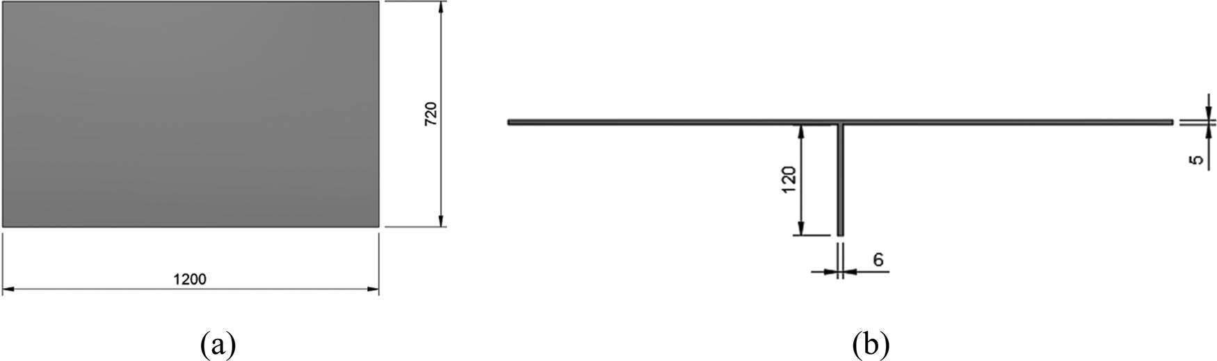
Illustration of a 2D thin-walled plate cross-section: (a) top-view plate cross-section and (b) side-view plate cross-section.
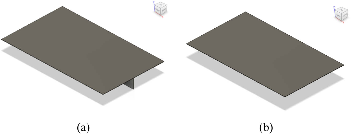
Three-dimensional plate design configurations: (a) stiffened plate using a FB and (b) unstiffened plate.
In this simulation, two material variations are used: low-carbon steel material with steel AISI 1006 85 HR and medium-carbon steel with the steel AISI 1045 HR HV specifications. A homogeneous material isotropic with elastic properties is assumed in this FEA. The physical properties of the two proposed materials are shown in Table 1.
Material physical properties for AISI 1006 and AISI 1045
| Material properties | AISI 1006 | AISI 1045 |
|---|---|---|
| Density | 7.872 × 10⁻⁶ kg/mm3 | 7.87 × 10⁻⁶ kg/mm3 |
| Modulus elasticity | 200,000 MPa | 200,000 MPa |
| Poisson’s ratio | 0.29 | 0.29 |
| Yield strength | 285 MPa | 450 MPa |
| Ultimate tensile strength | 330 MPa | 585 MPa |
2.2 Consideration of variation model scenario
In this section, the model scenario is based on a combination of the material type, stiffener use, type of loading, and direction of the loading angle. A total of eight main variations are analysed, starting with variations in the material type, FB stiffener utilisation, and type of loading. Further, from each of the variations, the simulations are then extended by investigating the influence of loading angles. In this work, the loading angle was varied in the direction of the positive Y-axis, namely, 0, 15, 30, 45, 60, and 75°. Furthermore, a total of 8 main variations with 48 simulations were comprehensively compared. Figure 3 illustrates the diagram of the simulation variation scenario.
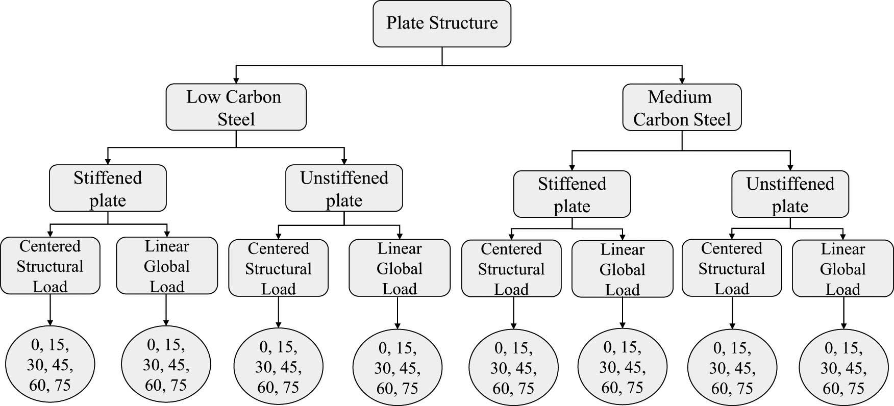
Diagram of the simulation variation scenario.
2.3 Finite element model discretisation
In this project, Autodesk Fusion 360 was used as the FEA platform for the modelling and simulation phases. The procedure used for FE simulation can be divided into three steps: (1) pre-processing was carried out, which involves modelling the geometry of the structures, meshing, and assembling the mass and stiffness matrices. The 3D conceptual modelling of stiffened and unstiffened structures was optimized using Autodesk Fusion 360; (2) finite analysis was performed in 48 simulation models using a static structural method to obtain structural responses; and (3) post-processing was used to evaluate the desired response output.
In the model discretisation, the stiffened plate was modelled using solid elements. Salomon [29] investigated topics similar to those covered in this paper and developed an analytical theory for describing various deflection phenomena in a shell model and 3D model (solid). The results demonstrated that the thickness of the modelled stiffener has a significant effect on the displacement solution. Before the principal analysis, a convergence assessment was carried out to find the appropriate mesh size for specific geometries with solid elements. In this work, element length-to-thickness ratios in the range of 5–10 were used to investigate structural responses – i.e., stress, displacement, and strain – to determine the most appropriate mesh size. In the FE setting, the mesh sizes were set to range from 10 to 70 mm. The results of the analysis indicated that the mesh size tends to be stable in the range of 20–50 mm, as can be seen in Figure 4.

Summary of the convergence assessment of the plate with one longitudinal stiffener.
In this regard, fixed constraints (U x = U y = U z = 0) were adopted on four sides of the plate. The plate was then given a static loading force with a magnitude of 5,000 N vertically (Y-axis) on the upper side of the plate, with the assumption there is no force in the other direction (X- and Z-axis). The load was carried out perpendicular to the upper section of the plate using two different scenarios – centred structural load and global linear load – as shown in Figure 5.
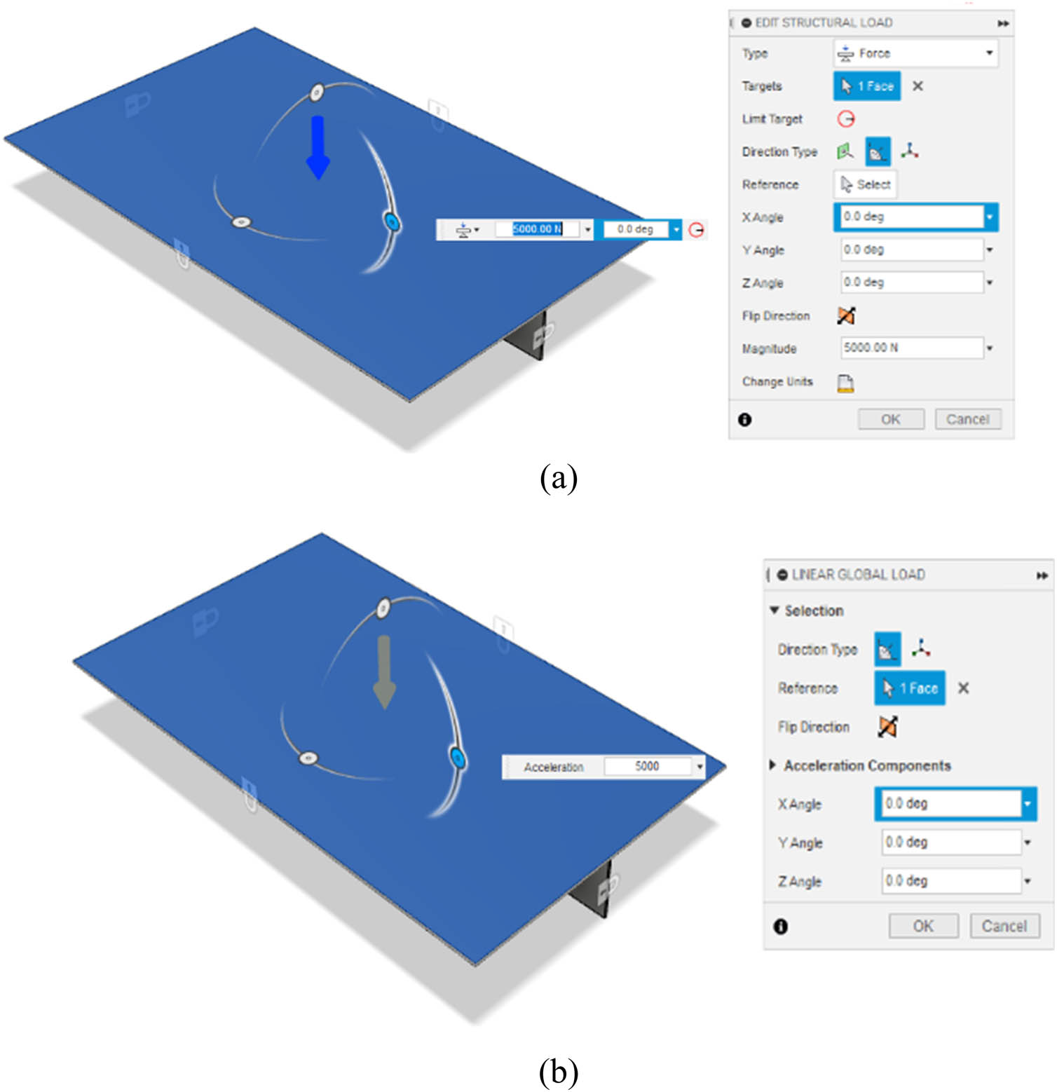
Loading conditions on the finite element geometry: (a) centred structural load and (b) global linear load.
3 Discussion of numerical results
3.1 Validation test
The responses to the FEA and experimental tests were compared for validation purposes considering the von Mises stress, displacement, and strain of the plates with one longitudinal stiffener (FB). In previous research [28], the authors performed a series of panel penetration tests with a cone-shaped indenter at the centre of the plate on a plate with one longitudinal stiffener. The geometrical configuration and set-up we used referred to the experimental test in this numerical analysis [28]. The validation test was conducted by analysing the penetration experimental result, as illustrated by force–indentation curves at a load 5,000 N. Table 2 shows the comparison of von Mises stress, displacement, and strain between the present study and the previous test for a plate with one longitudinal stiffener subjected to a centred structural load. The mean error of the numerical result at 8.7% indicates the good agreement of the proposed finite element modelling.
Validation test carried out for an FEA and experimental test
| Plate with one longitudinal stiffener | FEA (present study) | Experimental test [28] | Error (%) |
|---|---|---|---|
| Von Mises stress | 28.66 | 26.56 | 7.9 |
| Displacement | 0.121 | 0.135 | 10.4 |
| Strain | 0.00014 | 0.00013 | 7.7 |
3.2 Comparison result of von Mises stress
The strength assessment of ship plates is necessary in order to quantify the deformation and stress states and determine the relationships between the structural behaviour and structural parameters. The observations of von Mises stress show the von Mises stress between stiffened and unstiffened plates for all evaluated parameters. Here, it is also necessary to analyse whether the von Mises stress experienced by the plate exceeds the yield strength of the material or not. Figure 6 compares von Mises stress using stiffened and unstiffened low-carbon steel materials for different loading types and angles. These results show that both the stiffened and unstiffened plates experience stress reduction along with an increasing loading angle when subjected to a centred structural load or linear global load. It can be found that the highest stress value, which is 1,248 MPa, occurs in an unstiffened plate subjected to a global linear load at an angle of 0°. Meanwhile, the smallest stress value, which is 8.007 MPa, is experienced on a stiffened plate subjected to a centred structural load at the load angle of 75°. Further, the yield strength value of low carbon steel is assumed to be 285 MPa. Therefore, with a 5,000 N loading force, stiffened and unstiffened plates subjected to a global linear load enter a failure condition, because they have a value that exceeds the yield strength. However, the von Mises value of the plates subjected to centred structural load is still below the yield strength, as depicted in Figure 6.
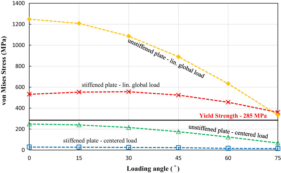
Maximum von Mises stress of stiffened and unstiffened low-carbon steel materials.
Next, Figure 7 presents the simulation result of the von Mises of stiffened and unstiffened medium-carbon steel material for different loading types and angles. The results show a similar phenomenon as the behaviour seen in the low-carbon material. In the stiffened and unstiffened plates subjected to both loading conditions, the von Mises stress decreases along with the increasing loading angle. It can be found that the highest stress value occurs in the unstiffened plate with a global linear load at an angle of 0°, for which the magnitude is about 1,244 MPa. Meanwhile, the smallest stress with a magnitude of 7.99 MPa occurs on a stiffened plate subjected to a centred structural load at an angle of 75°. It is known from the material data that the yield strength of the medium-carbon steel is 450 MPa. The stiffened and unstiffened plates subjected to global linear loads with a magnitude at 5,000 N experience a failure condition because the value exceeds the yield strength, except for the loading angle of 75° for both stiffened and unstiffened plates. However, the von Mises value of both plates subjected to centred structural loads is far below the yield strength in all evaluated loading angles.
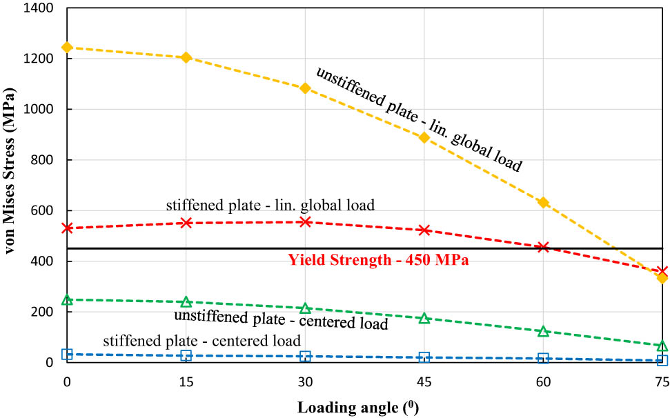
Maximum von Mises stress of stiffened and unstiffened medium-carbon steel materials.
3.3 Comparison result of the displacement value
This section uses a displacement value to determine displacement distribution experienced by plates due to the applied load. Figure 8 illustrates the total displacement calculated from the simulation of stiffened and unstiffened low-carbon steel plates. These results show that the displacement of both plates with two different applied loads decreases along with the increase in the direction of the loading angle. As seen in Figure 8, the highest displacement occurs on an unstiffened plate with a global linear load at an angle of 0° with a magnitude of 47.82 mm. In contrast, the stiffened plate with a centred load at an angle of 75° has the smallest displacement, with a magnitude of 0.04165 mm. Furthermore, the displacement data for stiffened and unstiffened medium-carbon steel plates are illustrated in Figure 9. The same phenomenon can be found compared to the displacement data shown in Figure 8. As can be seen, the displacement value decreases with the increase in the loading angle direction for all evaluated models. It can be found that the most significant displacement, with a value of 47.69 mm, occurs on an unstiffened plate with a global linear load with an angle of 0°, while the most minor displacement occurs on the stiffened plate subjected to a centred structural load with an angle of 75°.
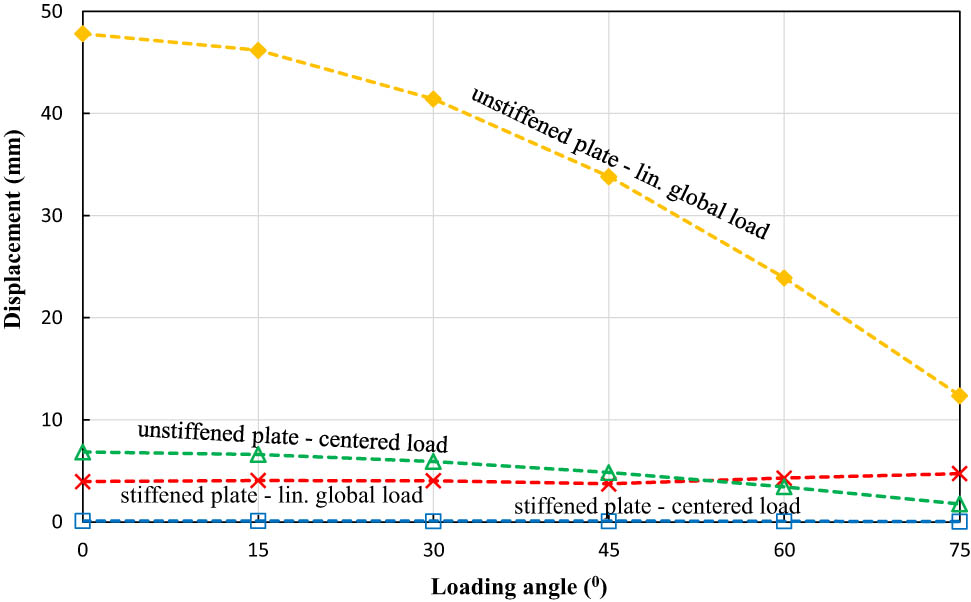
Maximum displacement value of stiffened and unstiffened low-carbon steel materials.
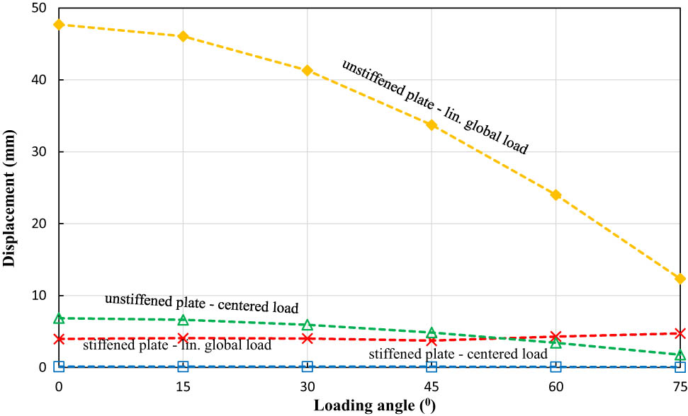
Maximum displacement value of stiffened and unstiffened medium-carbon steel materials.
3.4 Comparison result of the equivalent strain
Equivalent strain is a scalar quantity used to describe the state of the obtained strain. Figure 10 shows the equivalent strain data from the finite element result of both stiffened and unstiffened low-carbon steel plates. From these results, it can be seen that the equivalent strain decreases along with the increasing load angle for both types of materials. The largest equivalent strain, with a magnitude of 0.00557, can be found in an unstiffened plate with a global linear loading at an angle of 0°, while the smallest equivalent strain can be seen in a stiffened plate with a centred structural load at an angle of 75°. Further, the equivalent data for medium-carbon steel plates are illustrated in Figure 11. A similar phenomenon can be found in the equivalent data for low-carbon steel plates, where the largest equivalent strain occurs on an unstiffened plate with a global linear load at an angle of 0°. In contrast, the smallest value can be found in the stiffened plate with a centred structural load at an angle of 75°.
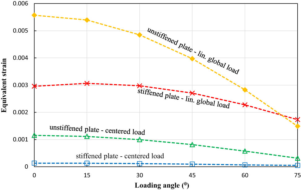
The equivalent strain of stiffened and unstiffened low-carbon steel materials.
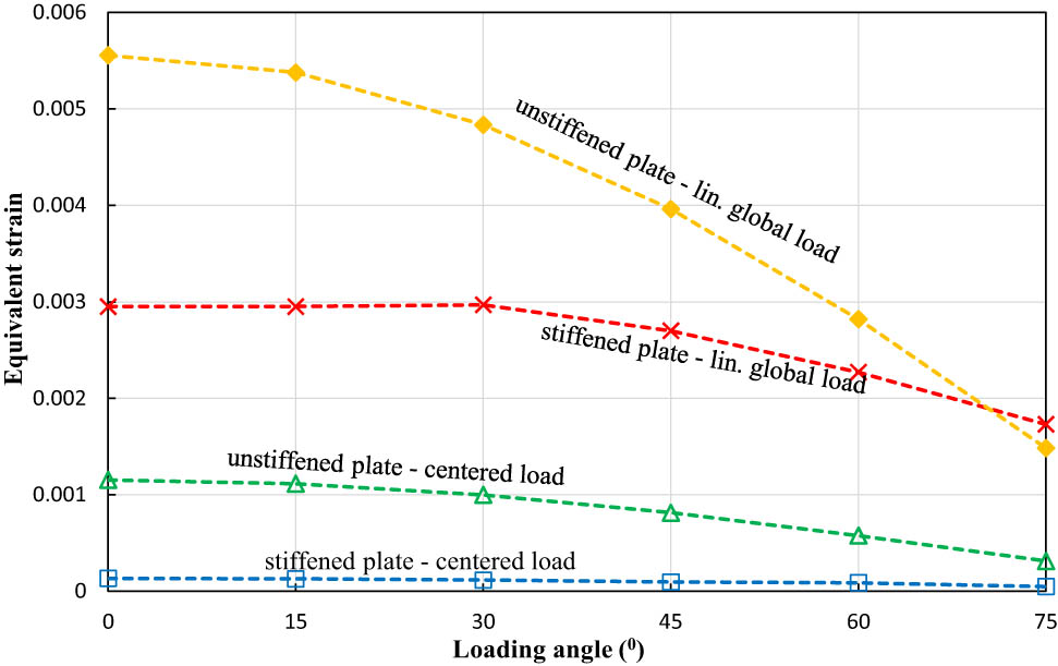
The equivalent strain of stiffened and unstiffened medium-carbon steel materials.
3.5 Overall discussion
As can be summarised from the analysis result, it was discovered that each variation and all the simulation parameters were unique. First, the material type parameter showing the difference between the low- and medium-carbon steel, as shown in Figures 6–11, reveals that the stress, displacement, and equivalent strain values recorded in low-carbon steel materials do not differ much from those found in medium-carbon steel. This may be because the plate has a similar geometry and cross-section. However, the maximum von Mises stress obtained from all models shows that low- and medium-carbon steels can be considered to fail when subjected to a force load of 5,000 N. In the FEA carried out using the low-carbon steel material, the highest stress occurs in an unstiffened plate with a global linear load at an angle of 0° and is equal to 1,248 MPa, whereas the yield strength of the low-carbon steel is only 285 MPa. Meanwhile, for medium-carbon steel material, the highest stress value recorded in the unstiffened load subjected to a centred structural load plate at an angle of 0° is 1,244 MPa, whereas the yield strength of this material is only 450 MPa. The other combination of variations was found using a simulation of variations with a stiffener. In the simulation, one flat plate is reinforced using a stiffener along the length of the plate. The shape and dimensions of the stiffener are presented in Figures 1 and 2, while the others are not given any reinforcement. In this variation, the plates that do not use a stiffener (unstiffened plate) have higher stress and displacement values than the stiffened plate, as reported in Figures 12 and 13. For the purpose of comparing the contour of the simulation results, Table 3 contains detailed information on eight main variation models.
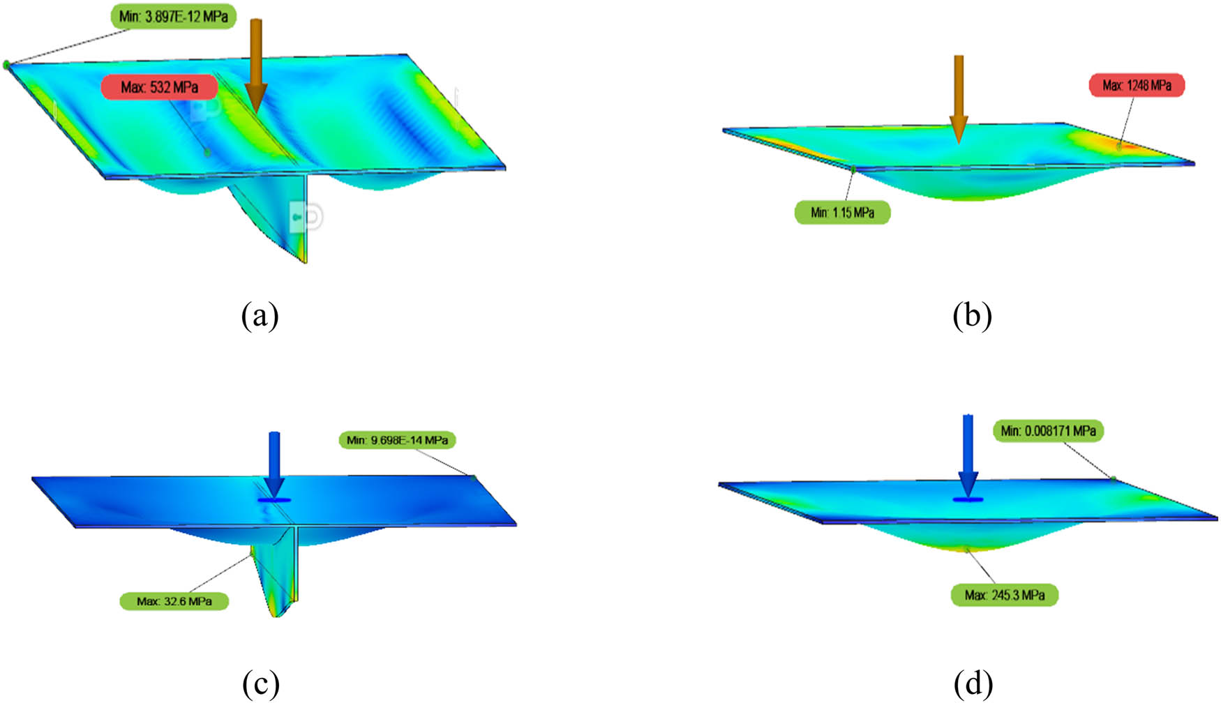
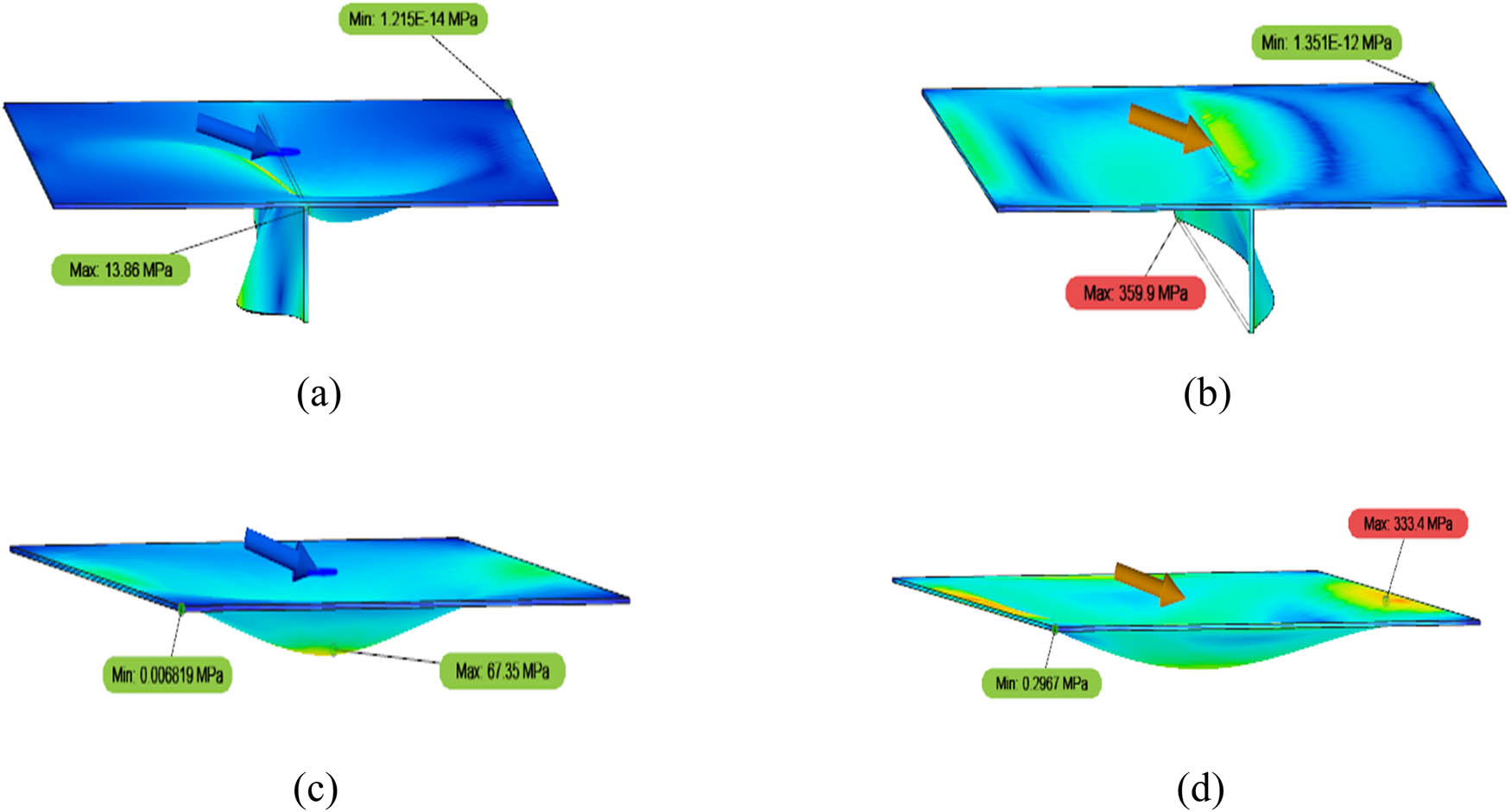
The contour of the von Mises stress simulation results between stiffened and unstiffened plates at a load angle of 0° for low-carbon steel with a global linear load (Models 2 and 4) and medium-carbon steel with a centred structural load (Models 5 and 7): (a) Model 2, (b) Model 4, (c) Model 5, and (d) Model 7.
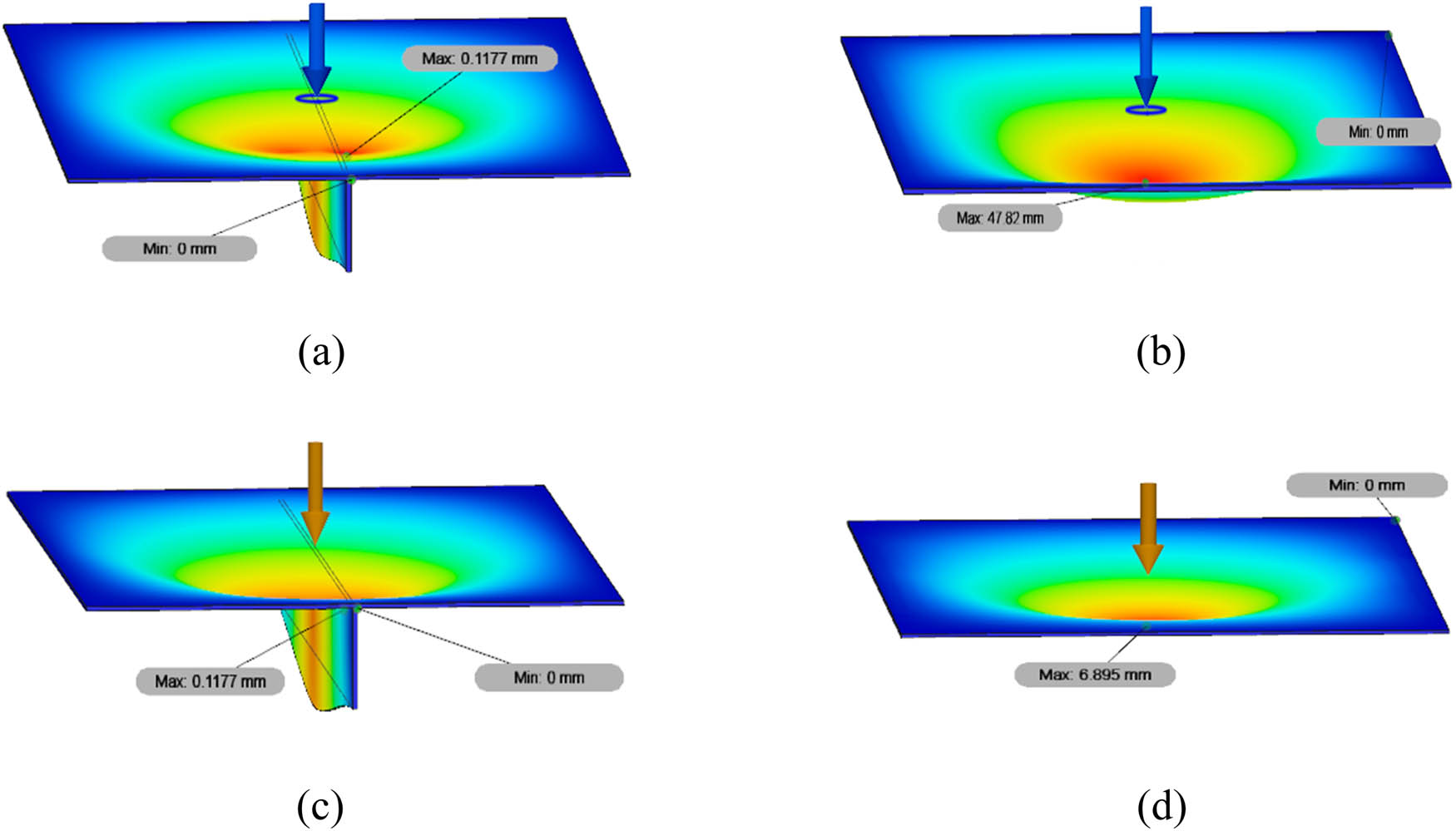
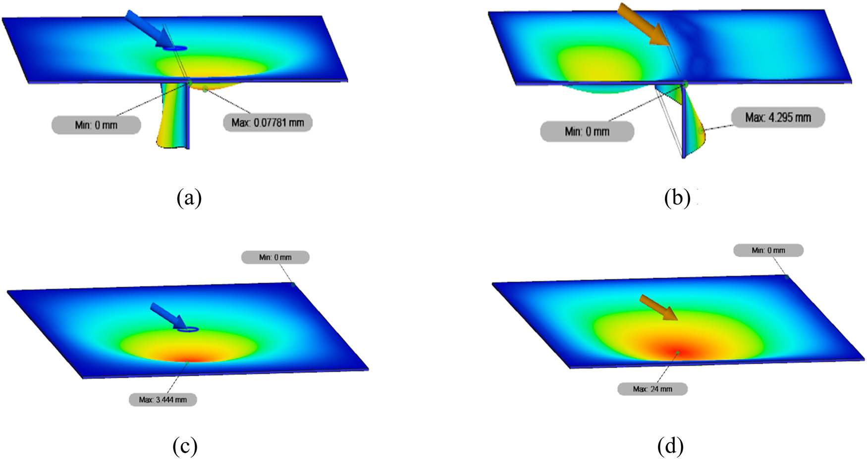
The contour of displacement at a load angle of 0° between stiffened and unstiffened low-carbon steel with a centred load (Models 1 and 3) and medium-carbon steel with a global linear load (Models 6 and 8): (a) Model 1, (b) Model 3, (c) Model 6, and (d) Model 8.
Eight main variation models
| Model | Variation details |
|---|---|
| 1 | Stiffened low-carbon steel plate with a centred structural load |
| 2 | Stiffened low-carbon steel plate with a global linear load |
| 3 | Unstiffened low-carbon steel plate with a centred structural load |
| 4 | Unstiffened low-carbon steel plate with a global linear load |
| 5 | Stiffened medium-carbon steel plate with a centred structural load |
| 6 | Stiffened medium-carbon steel plate with a global linear load |
| 7 | Unstiffened medium-carbon steel plate with a centred structural load |
| 8 | Unstiffened medium-carbon steel plate with a global linear load |
Figure 12 presents the contour of von Mises stress at a loading angle of 0° between stiffened and unstiffened plates. The maximum value recorded for von Mises stress in Model 2 (using stiffener) is 532 MPa, the maximum stress recorded for Model 4 (without stiffener) is 1,248 MP, the maximum stress recorded for Model 5 (using stiffener) is 32.6 MPa, and the maximum stress recorded for Model 7 (without stiffener) is 245.3 MPa. The data shown in Figure 12 demonstrate that the application of a stiffener can reduce the stress received by the plate, meaning that the plate becomes stronger.
Figure 13 displays the maximum displacement at a loading angle of 0°. The maximum total displacement of Model 1 (using stiffener) subjected to a centred structural load is 0.1177 mm, while that of Model 3 (without stiffener) is 47.82 mm. Moreover, in Model 6 (using stiffener) subjected to global linear load, the maximum total displacement value is 0.1177 mm, and that in Model 8 (without stiffener) is 0.6895 mm. The data provided in Figure 13 show that the application of a stiffener can reduce the displacement received by the plate, meaning that the plate becomes stronger.
In addition, it is important to take into account the uniqueness of the strain values for FB stiffener applications. Unstiffened plates tend to have a higher equivalent strain than plates that use a stiffener. In all simulations using plates with a stiffener, the minimum strain results are 0, while in plate simulations for plates without a stiffener, the results are less than 0, which varies according to the direction of the loading angle. This shows that the stiffener can reduce the force distribution received by the plate. All these facts can be seen in Figures 10 and 11.
Next, comparing the result gained between the two types of loadings, it can be seen that the centred structural and global linear loads have different characteristics. In global linear loads, the force is distributed over the surface of the plate, while in centred structural loads the force is concentrated at one point in the middle of the upper surface of the plate. In the variations of this type of loading, there is some uniqueness in that the stress, displacement, and strain values for the centred structural load are smaller than those for the global linear load. This is caused by the fact that the cross-sectional area of the plate subjected to a force in the simulation with a centred structural load is smaller than that subjected to a global linear load. The stress and displacement values are shown in Figures 14 and 15, and the strain values can also be seen in Figures 10 and 11.
The von Mises stress contour at a load angle of 75° between stiffened and unstiffened low-carbon steel plates with a centred load (Models 1 and 3) and global linear load (Models 2 and 4): (a) Model 1, (b) Model 2, (c) Model 3, and (d) Model 4.
The displacement contour at a load angle of 60° between stiffened and unstiffened low-carbon steel plates with a centred load (Models 5 and 7) and a global linear load (Models 6 and 8): (a) Model 5, (b) Model 6, (c) Model 7, and (d) Model 8.
Figure 14 presents the maximum von Mises stress at a load angle of 75° between stiffened and unstiffened low-carbon steel plates with centred loads and global linear loads. It can be seen that the maximum value of von Mises stress recorded for Model 1 (centred structural load) is 13.86 MPa, while in Model 2 (global linear load) it is 359.9 MPa. In Model 3 (centred structural load), the maximum von Mises stress is 63.75 MPa, and in Model 4 (global linear load) it is 333.4 MPa. This indicates that the stress on the central point load is smaller than the distributed load.
Figure 15 shows the maximum displacement at a load angle of 60° between stiffened and unstiffened low-carbon steel plates with centred and global linear loads. It can be seen that the maximum total displacement in Model 5 (centred structural load) is 0.07781 mm while that in Model 6 (global linear load) is 4.295 mm. Meanwhile, in Model 7 (centred structural load), the maximum total displacement value is 3.444 mm, and in Model 8 (global linear load), it is 24 mm. The results indicate that the displacement value in the centred structural load is smaller than the global linear load in all other types of loading variations.
In the final part, the influence of the use of loading angles of 0, 15, 30, 45, 60, and 75° is evaluated. The uniqueness of the simulation results with this variation is that almost all types of variations show the trend that the greater the angle of the load, the smaller the values of maximum and minimum stress, displacement, and strain. This can occur because the greater the loading direction angle, the less optimal load force is distributed across the plate. The comparison of stress and displacement values with the variation in loading angles is shown in Figures 16 and 17, and the strain values can be seen in Figures 10 and 11.
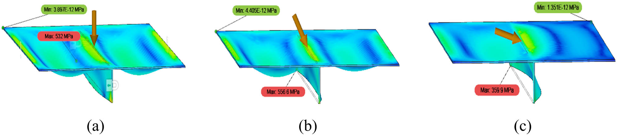
The contour of the von Mises stress of stiffened low-carbon steel material subjected to a linear global load (Model 2) at the loading angles of (a) 0°, (b) 30°, and (c) 75°.
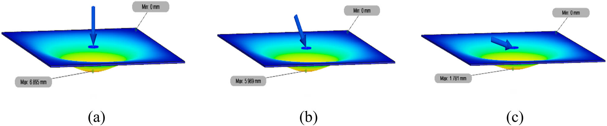
The displacement contour of unstiffened medium-carbon steel plates subjected to a centred structural load (Model 7) at the loading angles of (a) 0°, (b) 30°, and (c) 75°.
In Figure 16, the maximum values of von Mises stress in Model 2 with loading angles of 0, 30, and 75° are shown. The maximum value of von Mises stress at an angle 0° is 532 MPa; at 30°, the maximum is 556.6 MPa and at 75° the maximum is 359.9 MPa. Figure 17 shows the maximum values of the total displacement of Model 7 with loading angles of 0, 30, and 75°. As can be seen, the maximum total displacement value at an angle of 0° is 6,895 mm; at 30°, the maximum is 5,969 mm and at 75° the maximum is 1,781 mm. These data indicate that the greater the loading direction angle, the smaller the maximum stress value.
Furthermore, there is a peculiarity in the stiffened plate with a global linear load for both low- and medium-carbon steel materials. The greater the angle of loading, the greater the total displacement obtained. This may be due to the force on the global linear load across the surface of the plate when the applied loading force direction varies. The stiffener function in the middle of the plate as well as that perpendicular also seems less effective in withstanding the force load across the entire surface of the plate. As the loading direction is in the same direction as the positive Y-axis, the force will be more distributed across the plate side on the positive Y-axis, while on the plate side on the negative Y-axis the force load will be held back by the stiffener. Therefore, the greater the angle of the loading direction, the greater the force on the side of the plate on the positive Y-axis, meaning that a greater total displacement is obtained, as shown in Figure 18. The maximum displacement shown in Model 2 at an angle of 15° is 4.069 mm, while the maximum in Model 2 at an angle of 45° is 3.737 mm. In Model 6 at an angle of 15°, the maximum displacement is 4.058 mm, while that in Model 6 at an angle of 45° is 3.727 mm. The data given in Figure 18 show that the greater the loading angle, the higher the total displacement occurring in the plate.
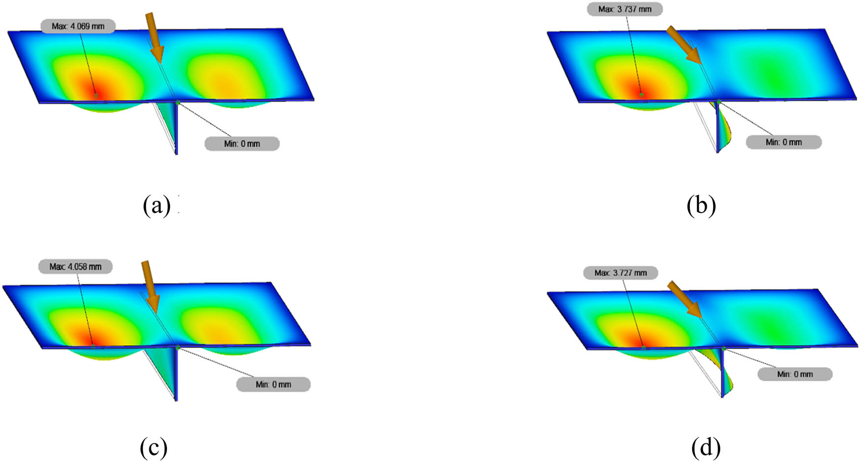
The displacement contour of stiffened low-carbon steel plate with a global linear load (Model 2) at an angle of (a) 15° or (b) 45° and stiffened medium-carbon steel plate with a global linear load (Model 6) at an angle of (c) 15° or (d) 45°.
4 Summary and concluding remarks
In this article, the influence of variations in the material type, stiffener, type of loading, and angle of loading on the von Mises stress, total displacement, and equivalent strain value was investigated using FEA. Based on the material applications, low- and medium-carbon steels were found to be unable to withstand a force load of 5,000 N, as seen from the maximum value of stress measured being greater than the yield strength value. In the next analysis, the stiffener application was considered to be adequate for strengthening the plate. It was shown through the simulation results that the plates for which no stiffener was used had greater stress, displacement, and strain values than the plates for which no stiffener was used. The stiffener can reduce the force distribution received by the plate. In all simulation variations in which stiffener was used, the minimum strain value was 0, while in the plate simulation for which no stiffener was used, the results were less than 0.
The values recorded for stress, displacement, and strain for plates with a centred structural load were smaller than those recorded for plates with a global linear load. This is due to the fact that in simulations with a centred structural load, the cross-sectional area of the plate subjected to the force is smaller than the cross-sectional area of the plate subjected to the force with a global linear load. By increasing the loading angle, the force received by the plate will be reduced because the force tends to point to the side of the plate rather than being fully distributed across the plate. Finally, in each simulation with global linear load and stiffener variations, the greater the angle of the loading direction, the greater the total displacement value. This is caused by the force load on plates with a global linear load being distributed fully across the entire surface of the plate, meaning that the stiffener function in the middle of the plate seems less effective in withstanding the force load applied across the whole surface of the plate.
-
Author contributions: All authors have accepted responsibility for the entire content of this manuscript and approved its submission.
-
Conflict of interest: The authors state no conflict of interest.
-
Data availability statement: The authors declare that all data supporting the findings of this study are available within the article.
References
[1] Zubaydi A, Haddara MR, Swamidas ASJ. Damage identification in a ship’s structure using neural networks. Ocean Eng. 2002;29(10):1187–200. 10.1016/S0029-8018(01)00077-4.Search in Google Scholar
[2] Prabowo AR, Tuswan T, Ridwan R. Advanced development of sensors’ roles in maritime-based industry and research: from field monitoring to high-risk phenomenon measurement. Appl Sci. 2021;11(9):3954. 10.3390/app11093954.Search in Google Scholar
[3] Jen CY, Tai YS. Deformation behavior of a stiffened panel subjected to underwater shock loading using the nonlinear finite element method. Mater Des. 2010;31(1):325–35. 10.1016/j.matdes.2009.06.011.Search in Google Scholar
[4] Kumar PR, Gupta G, Shamili GK, Anitha D. Linear buckling analysis and comparative study of un-stiffened and stiffened composite plate. Mater Today: Proc. 2018;5(2):6059–71. 10.1016/j.matpr.2017.12.211.Search in Google Scholar
[5] Paik JK, Kim BJ, Seo JK. Methods for ultimate limit state assessment of ships and ship-shaped offshore structures: part I-Unstiffened plates. Ocean Eng. 2008;35(2):261–70. 10.1016/j.oceaneng.2007.08.004.Search in Google Scholar
[6] Paik JK, Kim BJ, Seo JK. Methods for ultimate limit state assessment of ships and ship-shaped offshore structures: part II stiffened panels. Ocean Eng. 2008;35(2):271–80. 10.1016/j.oceaneng.2007.08.007.Search in Google Scholar
[7] Xu MC, Yanagihara D, Fujikubo M, Guedes Soares C. Influence of boundary conditions on the collapse behaviour of stiffened panels under combined loads. Mar Struct. 2013;34:205–25. 10.1016/j.marstruc.2013.09.002.Search in Google Scholar
[8] Bayatfar A, Khedmati MR, Rigo P. Residual ultimate strength of cracked steel unstiffened and stiffened plates under longitudinal compression. Thin-Walled Struct. 2014;84:378–92. 10.1016/j.tws.2014.07.002.Search in Google Scholar
[9] Leheta HW, Badran SF, Elhanafi AS. Ship structural integrity using new stiffened plates. Thin-Walled Struct. 2015;94:545–61. 10.1016/j.tws.2015.05.018.Search in Google Scholar
[10] Leheta HW, Elhanafi AS, Badran SF. A numerical study of the ultimate strength of Y-deck panels under longitudinal in-plane compression. Thin-Walled Struct. 2016;100:134–46. 10.1016/j.tws.2015.12.013.Search in Google Scholar
[11] Shi G-J, Gao D-W, Zhou H. Analysis of hull girder ultimate strength and residual strength based on IACS CSR-H. Math Probl Eng. 2019;2019:2098492. 10.1155/2019/2098492.Search in Google Scholar
[12] Kim DH, Paik JK. Ultimate limit state-based multi-objective optimum design technology for hull structural scantlings of merchant cargo ships. Ocean Eng. 2017;129:318–34. 10.1016/j.oceaneng.2016.11.033.Search in Google Scholar
[13] Ma H, Xiong Q, Wang D. Experimental and numerical study on the ultimate strength of stiffened plates subjected to combined biaxial compression and lateral loads. Ocean Eng. 2021; 228:108928. 10.1016/j.oceaneng.2021.108928.Search in Google Scholar
[14] Doan VT, Liu B, Garbatov Y, Wu W, Guedes Soares C. Strength assessment of aluminium and steel stiffened panels with openings on longitudinal girders. Ocean Eng. 2020;200:107047. 10.1016/j.oceaneng.2020.107047.Search in Google Scholar
[15] Tuswan T, Abdullah K, Zubaydi A, Budipriyanto A. Finite-element analysis for structural strength assessment of marine sandwich material on ship side-shell structure. Mater Today Proc. 2019;13(1):109–11. 10.1016/j.matpr.2019.03.197.Search in Google Scholar
[16] Tuswan T, Zubaydi A, Piscesa B, Ismail A, Ariesta RC, Ilham MF, et al. Influence of application of sandwich panel on static and dynamic behaviour of ferry ro-ro ramp door. J Appl Eng Sci. 2021;19(1):208–16. 10.5937/jaes0-27708.Search in Google Scholar
[17] Tuswan T, Zubaydi A, Piscesa B, Ismail A. Dynamic characteristic of partially debonded sandwich of ferry ro-ro’s car deck: a numerical modelling. Open Eng. 2020;10:424–33. 10.1515/eng-2020-0051.Search in Google Scholar
[18] Ismail A, Zubaydi A, Piscesa B, Ariesta RC, Tuswan T. Vibration-based damage identification for ship sandwich plate using finite element method. Open Eng. 2020;10(1):744–52. 10.1515/eng-2020-0086.Search in Google Scholar
[19] Prabowo AR, Cahyono SI, Sohn JM. Crashworthiness assessment of thin-walled double bottom tanker: a variety of ship grounding incidents. Theor Appl Mech Lett. 2019;9(5):320–7. 10.1016/j.taml.2019.05.002.Search in Google Scholar
[20] Prabowo AR, Putranto T, Sohn JM. Simulation of the behavior of a ship hull under grounding: effect of applied element size on structural crashworthiness. J Mar Sci Eng. 2019;7:270. 10.3390/jmse7080270.Search in Google Scholar
[21] Bae DM, Prabowo AR, Cao B, Zakki AF, Haryadi GD. Study on collision between two ships using selected parameters in collision simulation. J Mar Sci Application. 2016;15(1):63–72. 10.1007/s11804-016-1341-2.Search in Google Scholar
[22] Prabowo AR, Bae DM, Sohn JM, Zakki AF, Cao B, Cho JH. Effects of the rebounding of a striking ship on structural crashworthiness during ship-ship collision. Thin-Walled Struct. 2017;115:225–39. 10.1016/j.tws.2017.02.022.Search in Google Scholar
[23] Zhang M, Zhu Z, Zeng Y, Liu J, Hu Z. Analytical method for evaluating the impact response of stiffeners in a ship side shell subjected to bulbous bow collision. Math Probl Eng. 2020;2020:5025438. 10.1155/2020/5025438.Search in Google Scholar
[24] Silveira P, Teixeira AP, Figueira JR, Soares CG. A multicriteria outranking approach for ship collision risk assessment. Reliab Eng Syst Saf. 2021;214:107789. 10.1016/j.ress.2021.107789.Search in Google Scholar
[25] Calle MAG, Oshiro RE, Alves M. Ship collision and grounding: scaled experiments and numerical analysis. Int J Impact Eng. 2017;103:195–210. 10.1016/j.ijimpeng.2017.01.021.Search in Google Scholar
[26] Rigueiro C, Ribeiro J, Santiago A. Numerical assessment of the behaviour of fixed offshore platform subjected to ship collision. Proc Eng. 2017;199:2494–9. 10.1016/j.proeng.2017.09.415.Search in Google Scholar
[27] Zhu L, Liu W, Fang H, Chen J, Zhuang Y, Han J. Design and simulation of innovative foam-filled Lattice composite bumper system for bridge protection in ship collisions. Compos B Eng. 2019;157:24–35. 10.1016/j.compositesb.2018.08.067.Search in Google Scholar
[28] Alsos HS, Amdahl J. On the resistance to penetration of stiffened plates, part I – experiments. Int J Impact Eng. 2008;36:799–807. 10.1016/j.ijimpeng.2008.10.005.Search in Google Scholar
[29] Salomon A. An evaluation of finite element models of stiffened plates. United States: Massachusetts Institute of Technology; 2001.Search in Google Scholar
© 2021 Aditya Rio Prabowo et al., published by De Gruyter
This work is licensed under the Creative Commons Attribution 4.0 International License.
Articles in the same Issue
- Regular Articles
- Electrochemical studies of the synergistic combination effect of thymus mastichina and illicium verum essential oil extracts on the corrosion inhibition of low carbon steel in dilute acid solution
- Adoption of Business Intelligence to Support Cost Accounting Based Financial Systems — Case Study of XYZ Company
- Techno-Economic Feasibility Analysis of a Hybrid Renewable Energy Supply Options for University Buildings in Saudi Arabia
- Optimized design of a semimetal gasket operating in flange-bolted joints
- Behavior of non-reinforced and reinforced green mortar with fibers
- Field measurement of contact forces on rollers for a large diameter pipe conveyor
- Development of Smartphone-Controlled Hand and Arm Exoskeleton for Persons with Disability
- Investigation of saturation flow rate using video camera at signalized intersections in Jordan
- The features of Ni2MnIn polycrystalline Heusler alloy thin films formation by pulsed laser deposition
- Selection of a workpiece clamping system for computer-aided subtractive manufacturing of geometrically complex medical models
- Development of Solar-Powered Water Pump with 3D Printed Impeller
- Identifying Innovative Reliable Criteria Governing the Selection of Infrastructures Construction Project Delivery Systems
- Kinetics of Carbothermal Reduction Process of Different Size Phosphate Rocks
- Plastic forming processes of transverse non-homogeneous composite metallic sheets
- Accelerated aging of WPCs Based on Polypropylene and Birch plywood Sanding Dust
- Effect of water flow and depth on fatigue crack growth rate of underwater wet welded low carbon steel SS400
- Non-invasive attempts to extinguish flames with the use of high-power acoustic extinguisher
- Filament wound composite fatigue mechanisms investigated with full field DIC strain monitoring
- Structural Timber In Compartment Fires – The Timber Charring and Heat Storage Model
- Technical and economic aspects of starting a selected power unit at low ambient temperatures
- Car braking effectiveness after adaptation for drivers with motor dysfunctions
- Adaptation to driver-assistance systems depending on experience
- A SIMULINK implementation of a vector shift relay with distributed synchronous generator for engineering classes
- Evaluation of measurement uncertainty in a static tensile test
- Errors in documenting the subsoil and their impact on the investment implementation: Case study
- Comparison between two calculation methods for designing a stand-alone PV system according to Mosul city basemap
- Reduction of transport-related air pollution. A case study based on the impact of the COVID-19 pandemic on the level of NOx emissions in the city of Krakow
- Driver intervention performance assessment as a key aspect of L3–L4 automated vehicles deployment
- A new method for solving quadratic fractional programming problem in neutrosophic environment
- Effect of fish scales on fabrication of polyester composite material reinforcements
- Impact of the operation of LNG trucks on the environment
- The effectiveness of the AEB system in the context of the safety of vulnerable road users
- Errors in controlling cars cause tragic accidents involving motorcyclists
- Deformation of designed steel plates: An optimisation of the side hull structure using the finite element approach
- Thermal-strength analysis of a cross-flow heat exchanger and its design improvement
- Effect of thermal collector configuration on the photovoltaic heat transfer performance with 3D CFD modeling
- Experimental identification of the subjective reception of external stimuli during wheelchair driving
- Failure analysis of motorcycle shock breakers
- Experimental analysis of nonlinear characteristics of absorbers with wire rope isolators
- Experimental tests of the antiresonance vibratory mill of a sectional movement trajectory
- Experimental and theoretical investigation of CVT rubber belt vibrations
- Is the cubic parabola really the best railway transition curve?
- Transport properties of the new vibratory conveyor at operations in the resonance zone
- Assessment of resistance to permanent deformations of asphalt mixes of low air void content
- COVID-19 lockdown impact on CERN seismic station ambient noise levels
- Review Articles
- FMEA method in operational reliability of forest harvesters
- Examination of preferences in the field of mobility of the city of Pila in terms of services provided by the Municipal Transport Company in Pila
- Enhancement stability and color fastness of natural dye: A review
- Special Issue: ICE-SEAM 2019 - Part II
- Lane Departure Warning Estimation Using Yaw Acceleration
- Analysis of EMG Signals during Stance and Swing Phases for Controlling Magnetorheological Brake applications
- Sensor Number Optimization Using Neural Network for Ankle Foot Orthosis Equipped with Magnetorheological Brake
- Special Issue: Recent Advances in Civil Engineering - Part II
- Comparison of STM’s reliability system on the example of selected element
- Technical analysis of the renovation works of the wooden palace floors
- Special Issue: TRANSPORT 2020
- Simulation assessment of the half-power bandwidth method in testing shock absorbers
- Predictive analysis of the impact of the time of day on road accidents in Poland
- User’s determination of a proper method for quantifying fuel consumption of a passenger car with compression ignition engine in specific operation conditions
- Analysis and assessment of defectiveness of regulations for the yellow signal at the intersection
- Streamlining possibility of transport-supply logistics when using chosen Operations Research techniques
- Permissible distance – safety system of vehicles in use
- Study of the population in terms of knowledge about the distance between vehicles in motion
- UAVs in rail damage image diagnostics supported by deep-learning networks
- Exhaust emissions of buses LNG and Diesel in RDE tests
- Measurements of urban traffic parameters before and after road reconstruction
- The use of deep recurrent neural networks to predict performance of photovoltaic system for charging electric vehicles
- Analysis of dangers in the operation of city buses at the intersections
- Psychological factors of the transfer of control in an automated vehicle
- Testing and evaluation of cold-start emissions from a gasoline engine in RDE test at two different ambient temperatures
- Age and experience in driving a vehicle and psychomotor skills in the context of automation
- Consumption of gasoline in vehicles equipped with an LPG retrofit system in real driving conditions
- Laboratory studies of the influence of the working position of the passenger vehicle air suspension on the vibration comfort of children transported in the child restraint system
- Route optimization for city cleaning vehicle
- Efficiency of electric vehicle interior heating systems at low ambient temperatures
- Model-based imputation of sound level data at thoroughfare using computational intelligence
- Research on the combustion process in the Fiat 1.3 Multijet engine fueled with rapeseed methyl esters
- Overview of the method and state of hydrogenization of road transport in the world and the resulting development prospects in Poland
- Tribological characteristics of polymer materials used for slide bearings
- Car reliability analysis based on periodic technical tests
- Special Issue: Terotechnology 2019 - Part II
- DOE Application for Analysis of Tribological Properties of the Al2O3/IF-WS2 Surface Layers
- The effect of the impurities spaces on the quality of structural steel working at variable loads
- Prediction of the parameters and the hot open die elongation forging process on an 80 MN hydraulic press
- Special Issue: AEVEC 2020
- Vocational Student's Attitude and Response Towards Experiential Learning in Mechanical Engineering
- Virtual Laboratory to Support a Practical Learning of Micro Power Generation in Indonesian Vocational High Schools
- The impacts of mediating the work environment on the mode choice in work trips
- Utilization of K-nearest neighbor algorithm for classification of white blood cells in AML M4, M5, and M7
- Car braking effectiveness after adaptation for drivers with motor dysfunctions
- Case study: Vocational student’s knowledge and awareness level toward renewable energy in Indonesia
- Contribution of collaborative skill toward construction drawing skill for developing vocational course
- Special Issue: Annual Engineering and Vocational Education Conference - Part II
- Vocational teachers’ perspective toward Technological Pedagogical Vocational Knowledge
- Special Issue: ICIMECE 2020 - Part I
- Profile of system and product certification as quality infrastructure in Indonesia
- Prediction Model of Magnetorheological (MR) Fluid Damper Hysteresis Loop using Extreme Learning Machine Algorithm
- A review on the fused deposition modeling (FDM) 3D printing: Filament processing, materials, and printing parameters
- Facile rheological route method for LiFePO4/C cathode material production
- Mosque design strategy for energy and water saving
- Epoxy resins thermosetting for mechanical engineering
- Estimating the potential of wind energy resources using Weibull parameters: A case study of the coastline region of Dar es Salaam, Tanzania
- Special Issue: CIRMARE 2020
- New trends in visual inspection of buildings and structures: Study for the use of drones
- Special Issue: ISERT 2021
- Alleviate the contending issues in network operating system courses: Psychomotor and troubleshooting skill development with Raspberry Pi
- Special Issue: Actual Trends in Logistics and Industrial Engineering - Part II
- The Physical Internet: A means towards achieving global logistics sustainability
- Special Issue: Modern Scientific Problems in Civil Engineering - Part I
- Construction work cost and duration analysis with the use of agent-based modelling and simulation
- Corrosion rate measurement for steel sheets of a fuel tank shell being in service
- The influence of external environment on workers on scaffolding illustrated by UTCI
- Allocation of risk factors for geodetic tasks in construction schedules
- Pedestrian fatality risk as a function of tram impact speed
- Technological and organizational problems in the construction of the radiation shielding concrete and suggestions to solve: A case study
- Finite element analysis of train speed effect on dynamic response of steel bridge
- New approach to analysis of railway track dynamics – Rail head vibrations
- Special Issue: Trends in Logistics and Production for the 21st Century - Part I
- Design of production lines and logistic flows in production
- The planning process of transport tasks for autonomous vans
- Modeling of the two shuttle box system within the internal logistics system using simulation software
- Implementation of the logistics train in the intralogistics system: A case study
- Assessment of investment in electric buses: A case study of a public transport company
- Assessment of a robot base production using CAM programming for the FANUC control system
- Proposal for the flow of material and adjustments to the storage system of an external service provider
- The use of numerical analysis of the injection process to select the material for the injection molding
- Economic aspect of combined transport
- Solution of a production process with the application of simulation: A case study
- Speedometer reliability in regard to road traffic sustainability
- Design and construction of a scanning stand for the PU mini-acoustic sensor
- Utilization of intelligent vehicle units for train set dispatching
- Special Issue: ICRTEEC - 2021 - Part I
- LVRT enhancement of DFIG-driven wind system using feed-forward neuro-sliding mode control
- Special Issue: Automation in Finland 2021 - Part I
- Prediction of future paths of mobile objects using path library
- Model predictive control for a multiple injection combustion model
- Model-based on-board post-injection control development for marine diesel engine
- Intelligent temporal analysis of coronavirus statistical data