Effect of Boundary Conditions on Residual Stresses and Distortion in 316 Stainless Steel Butt Welded Plate
-
Dhayanithi Venkatkumar
 and
Durairaj Ravindran
and
Durairaj Ravindran

Abstract
In the present work, the prediction of residual stresses and distortion due to GTA welding process, a Finite Element (FE)Method has been developed and applied. Stainless steel plate of 3mm thickness is taken for the analysis. The prediction of residual stresses and distortion is performed by thermal and mechanical analysis that is sequentially coupled. The thermal analysis and mechanical analysis of the plate subjected to heat source movement have been studied consecutively. The FE analysis is performed in ANSYS software. In transient thermal analysis, Gaussian distribution model has been used for heat input of the arc. During modeling, the physical and mechanical properties that depend on temperature are considered. The heat transfer losses through all the three mechanisms are incorporated. For validating the FE simulated analysis, an experiment is conducted. The predicted thermal histories are very close agreement with measured thermocouple readings. After validation of thermal analysis results, the transient thermal histories are used as input for further mechanical analysis to simulate. The large displacement theory is used to conduct mechanical analysis. The effect of constraints on distortion and residual stresses are numerically studied. The predicted stresses and distortion results of different cases are discussed and presented.
1 Introduction
The distortion in components is resulting from the residual stress created in the material due to uneven heating and cooling process such as welding. The major factors influencing the residual stresses in the components are heat input, geometrical parameters, material property and location of fixtures. Articles related to the effect of location of fixtures are seldom found. Proper locations of fixtures are helpful in reducing the distortion and at the same time it enhances the residual stresses in the components [1]. In view of minimizing the distortion and residual stresses, the thorough knowledge about the location of fixtures and mechanism of distortion is essential. The distortion over components arises due to the residual stresses and transient thermal strains during manufacturing process that involve localized heating. The higher magnitude in residual stress causes loss of performance in corrosion, fatigue and fracture. The increased distortion causes the poor dimensional accuracy and parts are liable to be rejected during assembly section and increase the reworking cost.
FE is an effective tool towards predict thermal histories, residual stresses and distortion in components when a heat source is made to move over its surface [2, 3]. The constraint during the FE plays a vital role in simulation of residual stresses and distortion. Several researchers applied single point constraints in view of predicting the residual stress of the components in their study. The constraints are having greater influence in the residual stress created in the components. The appropriate selection of constraints is essential to control the distortion of components in practical applications. The research and analysis pertaining to the effect of constrains are seldom found in literatures.
Chen et al. [4] developed FEM for the prediction of temperature distribution,welding residual stresses and distortion in Gas Tungsten Arc (GTA) welded joints. Heat source model based on double ellipsoidal was employed in transient heat transfer analysis to predict thermal histories. Venkatkumar and Ravindran [5] investigated the effect of surface and volumetric heat source on thermal histories. The effect of large and small displacement theory on residual stresses and distortion are also studied [5]. Chang et al. [6] investigated the residual stress are developed in T-joint fillet welds. In their study, the heating of the welding arc was modeled with Gaussian surface heat distribution and molten droplets were modeled by volumetric heat source. Hashemzadeh et al. [7] examined the effect of thickness on vertical deflection in thin stainless steel plates. Zubairuddin et al. [8] studied residual stresses and distortion in chromium steel by sequentially coupled thermomechanical analysis. The authors reported that the distortion can be accurately estimated using large distortion theory. Wang et al. [9] modeled the prediction of longitudinal bending and angular distortion in T-joints and the deformation was predicted using large deformation theory. Adak et al. [9] investigated the effects of restraints on the weld induced stresses and distortion in the plate. Further, the mechanical responses of the plate under different constraint conditions were investigated and the effects on plate geometry and mesh models were also studied [10]. Ninshu et al. [11] investigated the jig constraint effects on welding deformation under non constraint and jig constraint boundary conditions. Robert et al. analyzed angular distortion in Metal Inert Gas welding process. In their study, the rigid clamping boundary conditions were defined to predict the welding deformation. Heinze et al. [13] reported the results pertaining to high restraint conditions on welding residual stresses. The authors had studied the restraint transverse shrinkage and free shrinkage in various restraint cases. Li et al. [14] analyzed the effect of flowing water on temperature and residual stresses induced. They found that the inner surface temperature and weld induced residual stresses were extensively influenced by flowing water. Yupiter et al. [15] reported that the effect of welding sequence on angular distortion on low carbon steel. Xu et al. [16] predicted axial distortion in girth-butt welded pipes of various wall thicknesses.
In the present study, the effects of constraints have been analyzed using 3D sequentially coupled thermo mechanical analysis [1, 3] in FEA and the results are presented. The residual stresses and distortion are predicted for five different fixture conditions using large displacement theory. The FEM model has been validated for its prediction of thermal histories with experimental procedures. The constraints are fixed at specified distance from the weld centre line and the effect with respect to distortion and residual stress are predicted and discussed.
2 Computational Procedure
In view of predicting the influence of fixture locations during welding processes on residual stresses and distortion of components, a FEM has been developed in ANSYS environment. The above study is carried out in two successive phases. In first phase, the transient thermal analysis has been carried out to simulate the thermal histories and validated those using experimental results. Gaussian heat distributed model is employed for the study. The dynamic motion of the heat source has also been modelled and performed transient analysis. In second phase, the results predicted from thermal analysis are taken as input for predicting residual stress and distortion using mechanical analysis for different fixture locations. The detailed procedure of the construction details of the substrate material model, boundary conditions, modelling of heat source, validation and fine tuning of FEM and distortion under various fixture positions are presented in subsequent sections.
3 Thermal Analysis
3.1 FE Model of the substrate Material
The substrate material for the study considered is 316 stainless steel plate of size 125 × 150 mm and thickness 3mm. Initially, the substrate has been modelled using direct node generation technique using ANSYS Parametric Data Language (APDL). The model is developed using three dimensional, eight node brick elements (SOLID70) with single degree of freedom [5, 10]. Near the weld zone, very fine mesh sizes are used and it gets coarsened as it moves away from the weld zone. The minimum size of the element has been 0.24mm× 1mm× 0.5 mm. The FE model contains of 44450 nodes and 37044 elements for both the plates.
3.1.1 Material properties and Boundary conditions
The material properties such as thermal conductivity, specific heat capacity and density are highly temperature dependent. Since the transient thermal analysis is performed at higher temperatures, it is absolutely essential to employ the physical properties of the material corresponding to the temperature of the specimen during the heating process. The temperature dependent material properties corresponding to 316 stainless steel is presented in Table 1. The data presented in the Table 1, are taken from the published articles by various researchers [17, 18, 19]. Further, the heat losses from the heat source during welding process are inevitable. A due consideration is to be given in order to tune the FE model to represent the actual welding conditions. The major heat losses are by means of convection and radiation. The combined heat transfer coefficient for the heat losses are given by the following Equation (1) as proposed by Kyong-Ho et al. [6] and it is applied for all the free surfaces of the model.
Thermo-mechanical properties of 316 Stainless Steel.
| Temp. (∘C) | Density (Kg/m3) | Conductivity (W/m∘C) | Specific heat (J/g ∘C) | Co.eff of Thermal Exp. (1×10⁻⁶/∘C) | Young’s modulus (GPa) | Poisson’s ratio | Yield Stress (MPa) |
|---|---|---|---|---|---|---|---|
| 20 | 8030.47 | 13.63 | 464.73 | 15.24 | 196 | 0.267 | 320 |
| 100 | 7997.02 | 14.99 | 494.23 | 15.80 | 188 | 0.273 | 211 |
| 200 | 7954.03 | 16.62 | 522.74 | 16.43 | 180 | 0.290 | 167 |
| 300 | 7909.76 | 18.19 | 543.92 | 16.97 | 172 | 0.310 | 145 |
| 400 | 7864.18 | 19.72 | 559.87 | 17.44 | 164 | 0.322 | 135 |
| 500 | 7817.31 | 21.26 | 572.69 | 17.85 | 156 | 0.313 | 129 |
| 600 | 7769.13 | 22.81 | 584.49 | 18.21 | 148 | 0.296 | 123 |
| 700 | 7719.66 | 24.42 | 597.368 | 18.54 | 139 | 0.282 | 117 |
| 800 | 7668.90 | 26.09 | 613.45 | 18.83 | 131 | 0.262 | 111 |
| 900 | 7616.83 | 27.86 | 634.82 | 19.11 | 123 | 0.240 | 105 |
| 1000 | 7563.47. | 29.76 | 663.58 | 19.38 | 112 | 0.229 | 99 |
| 1100 | 7508.81 | 31.81 | 701.85 | 19.66 | 94.4 | 0.223 | 66 |
| 1200 | 7452.85 | 34.03 | 751.72 | 19.95 | 11.7 | 0.223 | 43 |
| 1300 | 7395.60 | 36.46 | 815.30 | 19.95 | 7.0 | 0.223 | 13.5 |
| 1400 | 7354.75 | 38.29 | 869.09 | 20.7 | 5.56 | 0.223 | 10 |
Where To = 26∘C is the room temperature, σ = 5.67 × 10⁻⁸J/(m2K4s) is Stefan-Boltzmann constant. hc = 15 W/m2K is convection heat transfer co-efficient, ε = 0.2 is emissivity. The solidification effect of weld pool modelled by considering latent heat for fusion. The value of latent heat is 270 J/g, The solidus and liquidus temperatures are 1450∘C and 1500∘C, respectively [20].
3.1.2 Modeling of Heat source
The accuracy of the predicted transient thermal histories mainly depends upon the careful selection and modeling of heat source. However, various heat sources have been employed by various researchers, the moving Gaussian heat source modeled used by Friedman [5, 20] is employed in the present study owing to its better distribution of heat at various points within the geometrical zone of the heat source. The moving welding arc is modeled as a Gaussian surface heat flux distribution following the Equation (2) as given below.
Where Q = welding heat input, rb = radius of arc (taken as 3mm) and X, Z = the coordinates within the arc radius. The Gaussian heat source is a model in which heat generated over a surface; therefore, it may be suitable to be applied to thin plates. In this work, the thickness of the plate used is 3 mm.
Heat input ‘Q’ is calculated for the welding current 100 A and voltage 24 V. The welding arc efficiency is considered as 85%. The welding speed of the arc is 2.415 mm/s. The heat source is simulated to move along a weld centre line. In the simulation, a plate is assumed to be fixed and the heat source is moved over the surface of the plate. It is achieved using APDL programming in ANSYS. Initially, the elements covered under the heat source are selected for the heat supply for specified time steps. The Newton-Raphson technique is employed for heat balance iteration [5].
The ANSYS time increment for each time step has been calculated automatically. The effects produced over a particular element over the plate by the previous step are carried forward to the next step. The velocity of moving heat source is decided based on the welding torch speed. The Gaussian surface heat flux distribution of the welding arc of specified radius is illustrated in Figure 1 showing the variation of the heat flux in different colors.
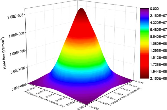
Gaussian surface heat flux distribution of welding arc.
3.1.3 Validation of Finite Element Model in Thermal Analysis
The predicted thermal histories are used as input to the FE model in stress analysis for the simulation of weld residual stresses and distortion. The output results from the mechanical analysis are highly depending on the accuracy of thermal model. Hence, thermal model is validated using experimental results. The results comparison between predicted and measured is presented in results and discussion section.
The K-type thermocouples of size 0.5 mm diameter are fixed at the top surface of the plate by spot welding process using trained skill technicians. The temperature distribution during the welding process is measured at specific points as shown in Figure 2.
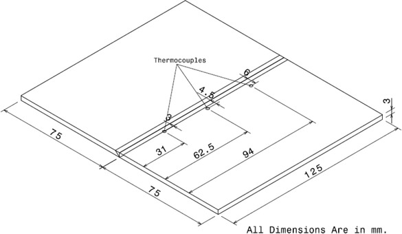
Schematic diagram of butt joint specimen and location of Thermocouples.
The output of thermocouples is connected to the data logger which is interfaced with computer to store the thermal histories at every millisecond interval. The automatic torch moving mechanism is used to perform the welding process. The experimental setup is shown in Figure 3. During the experiment the specimen is fully restrained during heating and cooling process of welding.
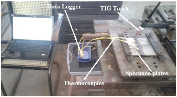
Experimental setup
3.1.4 Mechanical (Structural) Analysis
In the view of predicting residual stresses and distortion, the same FE model used in thermal analysis is employed by switching the element from thermal to structural and constraint boundary conditions. The SOLID185 element is used to calculate the residual stresses and distortion [10]. The predicted transient thermal histories are used as input in mechanical analysis. Creep behavior of the material is ignored as the material experiences high temperatures for a short duration of time [17]. The total strain rate developed in the material is expressed as the summation of elastic, plastic and thermal strains. The elastic strain is modeled by isotropic Hook’s law with temperature dependent young’s modulus and Poisson’s ratio. For the plastic strain, the linear isotropic hardening rule and von-mises yield surface are taken into account [3, 10, 21, 22]. Further, the thermal expansion co-efficient is used to model thermal strain. The welding distortion in the components is strongly depending on the position of fixtures during welding process. Hence, in this analysis, the boundary conditions (location of fixtures) are chosen so as to calculate the weld residual stresses and distortions. In view of analyzing the effect of the constraint positions on residual stresses and distortion, the study is performed by locating the fixtures at five different cases.
The boundary condition for the structural analysis for different cases is shown in Figure 4(a) to 4(c). Figure 4(a) illustrates the boundary conditions of the plate with no constraints (without clamping). The rigid body motion is prevented by fixing the body as shown in the Figure 4(a) by constraining three corners and one corner is left free to allow the free expansion of the material [6, 7, 23, 24].
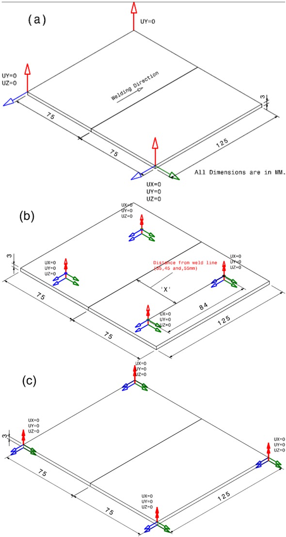
Boundary conditions for mechanical analysis: (a) No constraint (Prevent Rigid body motion) (b) fully constraint at mid nodes and (c) fully constraint at corner nodes.
One of the corners is arrested in all the three directions. Another corner is arrested in ‘y’ and ‘z’ direction whereas the remaining one is arrested in ‘y’ direction alone. Figure 4(b) illustrates, the position of the fixtures at four locations which are at the distance ‘x’ from the centre line and it is considered as 8 nodes (4 nodes on each side) is constrained completely [15]. The distance ‘x’ is varied as 35, 45 and 55mm. Figure 4(c) illustrates the constraints are applied at extreme corner nodes at both bottom and top surfaces of the plates.
4 Results and Discussion
The results with discussion pertaining to the prediction of temperature, residual stress and distortion are described in following stages.
4.1 Thermal Analysis
The comparisons of the results obtained with regard to temperature distribution are presented from Figure 5(a) to (c) The plots show the temperature measured using thermocouples and simulation at the distances from the centre line of 3, 4.5 and 6mm. It is inferred from the plots that the experimentally measured results are closely following the simulation results at the distances of 3 and 4.5 mm with regard to Figure 5(a) and 5(b) It is shows that the heating and cooling periods of test data are in very close agreement with numerically predicted results. However, in Figure 5(c) the thermocouple location at 5.5 mm from the centre line could not be obtained in modeling as the node is present at 6 mm only. In Figure 5(c) the variation in the temperature difference between measured and predicted is due to the difference in location of thermocouple in experimentation and modeling. It is shows that the heating and cooling periods of test data are in very close agreement with numerically predictions.
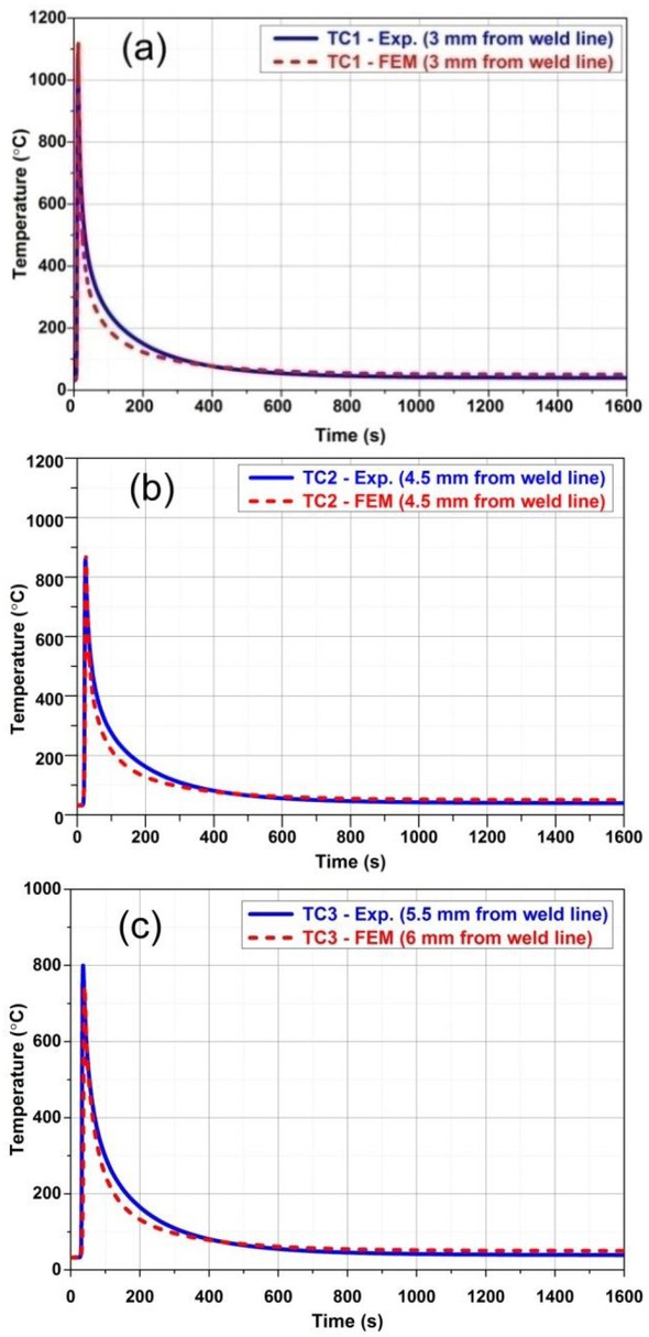
Comparison of temperatures in experiment and simulation (TC1, TC2 and TC3)
The percentage error of numerical predicted results with the experimental measurements are presented in Table 2 The temperature recorded by a particular thermocouple is presented for the time interval of 0 to 1600 seconds of the plate. The cooling curve is plotted with the thermal histories recorded for the complete movement of heat input and allowed the plate till reaches ambient temperature. Further, it is noticed that, the maximum temperature is recorded when the moving heat source is near to the thermocouple location and it is having close agreement with FEM result. Figure 6(a) to 6(d) shows the predicted temperature distribution during simulation at various time intervals of heating and cooling process of welding. It is shows that the heating and cooling periods of test data are in very close agreement with numerically predictions.
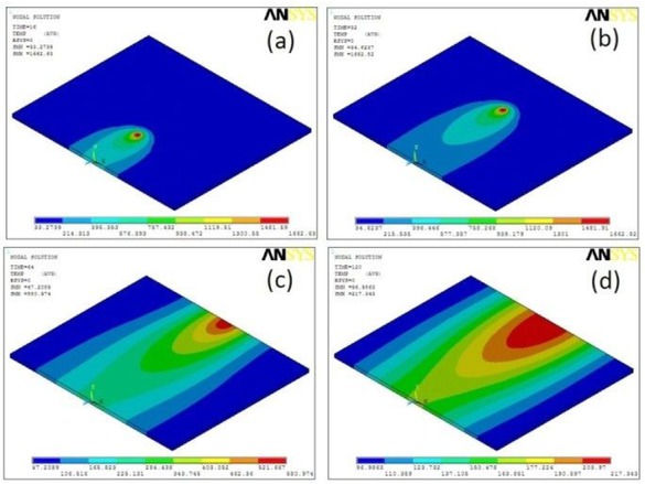
Simulated Temperature histories at various time intervals: (a) 16 sec (b) 32 sec (c) 64 sec and (d) 120 sec.
The Peak temperatures comparison between experimental and numerical results
| Thermocouple | Distance from weld centre line | Experimental results Temp (∘C) | Numerical results Temp (∘C) | Error (%) |
|---|---|---|---|---|
| TC1 | 3 mm | 1086.37 | 1118.38 | 2.862 |
| TC2 | 4.5 mm | 860.12 | 874.836 | 1.682 |
| TC3 | 6 mm | 799.64 | 746.112 | 7.174 |
4.2 Mechanical Analysis
In the mechanical analysis, large displacement theory is employed to analyze the weld induced residual stresses and distortions [5, 8]. In this analysis, validated thermal histories are used. The residual stresses are obtained in all x (Transverse) y (Through Thickness) and z (Longitudinal) directions for all the boundary conditions. The boundary conditions have significant influences on residual stresses in particular longitudinal and Hence, the variation of residual stress in ‘x’ and ‘z’ directions are predicted. The results obtained for various boundary conditions as described in mechanical analysis section, are presented in Table 3
Predicted Maximum Residual Stresses and deflection in the plate under various cases.
| Cases | Constraint Type | Sz-Longitudinal Max. | Stress (MPa) Min. | Sx-Transverse Max. | Stress (MPa) Min. | Deflection (mm) |
|---|---|---|---|---|---|---|
| Case “A” | No Constraint | 332 | −209 | 173 | −305 | 1 |
| Case “B” | 35 mm from weld line | 342 | −291 | 177 | −306 | 0.494 |
| Case “C” | 45 mm from weld line | 342 | −262 | 186 | −310 | 0.581 |
| Case “D” | 55 mm from weld line | 337 | −216 | 290 | −311 | 0.6 |
| Case “E” | Corner nodes fixed | 329 | −208 | 226 | −312 | 1.05 |
The residual stresses and distortions at top and bottom surfaces of the plate with no constraint and fully constraint conditions are carried out at distance 35, 45 and 55mm from mid span of the weld centre line. Figure 7 illustrates the residual stress distribution at both top and bottom surfaces of the plate for no constrained case. In similar way, the same type of results at full constraint case at 45mm from weld line is also shown in Figure 8
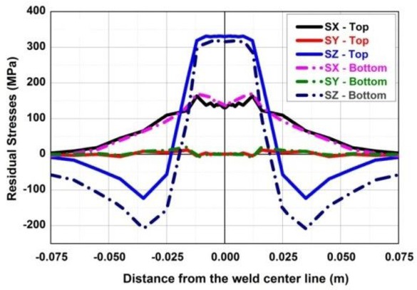
Simulated Welding residual stresses at mid span of weld centre line– No constraint (Case A)
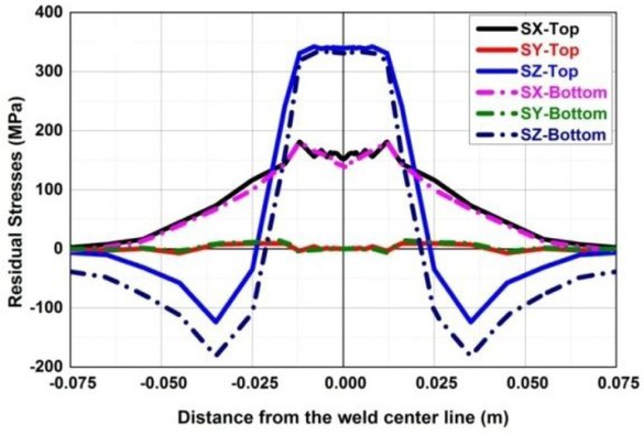
Simulated welding residual stresses at mid span of weld centre line – Fully constraint at nodes from 45 mm (Case C).
The peak value of longitudinal stress at top surface is fairly higher than that of stress in bottom surface. It is inferred that the residual stress distribution in top and bottom surfaces are similar as the thickness of the plate is considered as minimum. In case of larger thickness, the stress pattern will not be same as the heat source is moved only on top surface of the plate. The residual stress distribution in longitudinal direction is higher in fully constraint case than the case of no constrained. It is attributed to the free movement of the plate in no constrained case whereas in fully constrained, the plates are restricted to displace in vertical direction.
The distributions of simulated vertical displacement in the y direction under no constraint and fully constraint (Case C) condition are shown in Figures 9 (a) and (b) Near the weld line, higher magnitude tensile stresses are noticed and the lower magnitude compressive stresses are noticed away from the weld line.
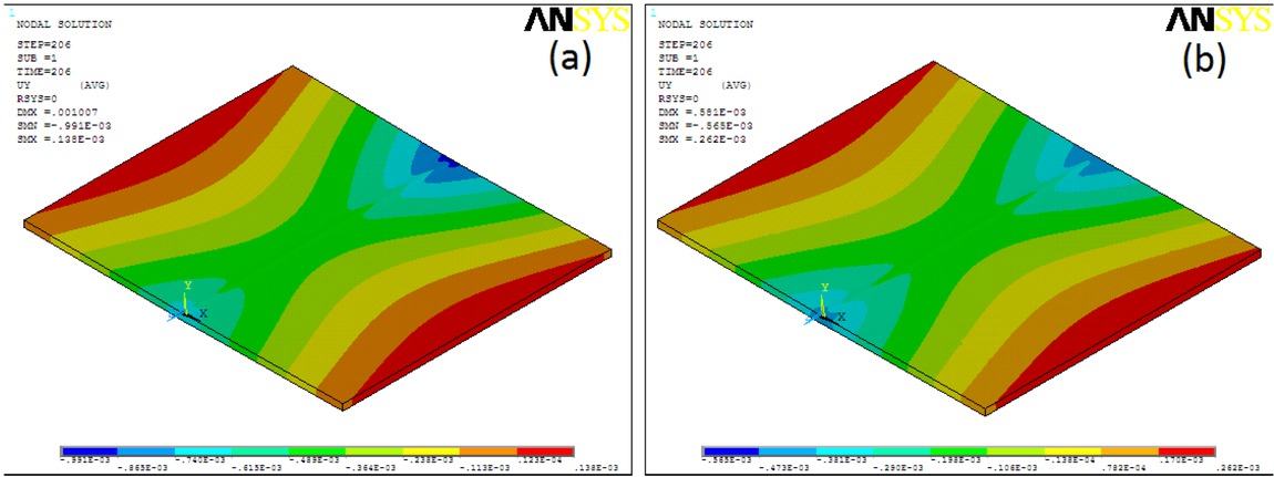
Vertical deflection distribution: (a) No Constraint and (b) Fully constraint (Case C).
It is noticed that higher in fully constraint case than the case of no constrained. It is attributed to the free movement of the plate in no constrained case whereas in fully constrained, the plates are restricted to displace in vertical direction. The distributions of simulated vertical displacement in the y direction under no constraint and fully constraint (Case C) condition are shown in Figure 9(a) and 9(b) Near the weld line, higher magnitude tensile stresses are noticed and the lower magnitude compressive stresses are noticed away from the weld line. It is noticed that the higher temperature is present at the weld line and it decreases when moving towards the edge of the plate. As the heat source is moving in the longitudinal direction, it is evident that the stresses in the longitudinal direction are greater than the transverse direction.
The distortion of the plate is eventually happening as the residual stresses exceed than the yield stress. In the present case, the yield stress of the 316 steel is 320 MPa. The magnitude of the peak values of stress in longitudinal direction is at the mid span of the surface. At the top surface its value is 342MPa and at the bottom its value is 334MPa.
From Table 3 It’s observed that the deformation has been greatly reduced by fully constraint condition than no constraint condition. The reason for getting less distortion in fully constrained case is as explained in earlier the displacement is restricted and it is interesting to note that the stress value is increased because of the constraints. It is also observed that the deformation is also varies as the location of restrain from the weld centre line. As an example, the restrain provided at the distance of 35mm is lesser than the restrain provided at the corner nodes.
The variations of plate deflection on weld center line in vertical direction at top surface of all cases are shown in Figure 10. It is observed that the deflection is in minimum in case B which is at 35mm from the weld line and nearer one. The simulated results revealed that the deflection in y direction at the weld line of the plate is larger than at the edge of the plate. During the heating process the large compressive plastic strains are developed due to constraint conditions. This is because the material expansion is greatly restrained by the fixtures and as a result the compressive strains become larger comparing with the no constraint cases. The longitudinal residual stress distribution at the top surface of the plate for all the cases are presented in the Figure 11 (a-e) Due to the effect of constraint the maximum residual stress appears in the fixtures location in addition to the weld line. In the no constraint cases the maximum longitudinal stress developed only at the fusion zone and heat affected zone.
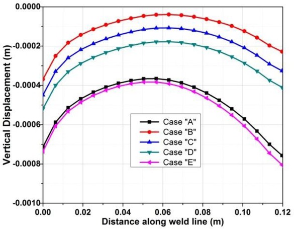
Simulated Vertical Displacement along weld line.
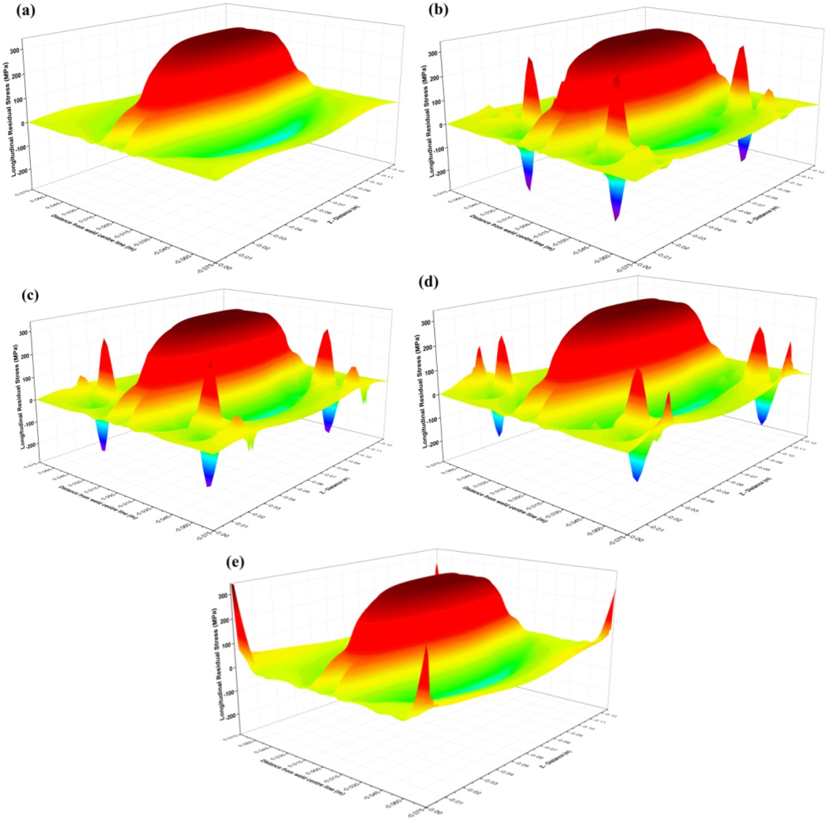
Predicted longitudinal residual stress distribution in top surface of the plate (a) Case ‘A’, (b) Case ‘B’, (c) Case ‘C’, (d) Case ‘D’, (e) Case ‘E’.
5 Conclusion
In view of predicting temperature distribution, residual stress and distortion of the plate, a systematic analysis has been proposed. The method is based on thermal analysis and its validation. Further, the fine tuned model is analyzed for its mechanical stress and distortion. Thermal analysis and mechanical analysis have been performed sequentially. Predicted transient thermal histories have been validated with experimental results. In mechanical analysis the results of thermal analysis have been utilized. The effect of position of fixtures at five different locations have been modeled as constraints and studied elaborately. The result shows that the welding residual stresses and distortions are influenced as a result of the constraints. The predicted results revealed that the vertical distortion has been greatly reduced when the fixtures are used. Generally the vertical distortion will be reduced when the fixtures are located very nearer to the weld centre line. It is suggested to use the above analysis for the design of fixture positions during welding or any process that involves heat input to extend of creating distortion due to uneven heating and cooling.
References
[1] D. Casassola Gonçalves, M. Campos Martins, M. P. Cindra Fonseca, Soldagem Insp., 22(2) (2017) 147-162.10.1590/0104-9224/si2202.05Search in Google Scholar
[2] M. Farajpour and E. Ranjbarnodeh, Soldagem Insp., 23(1) (2018) 60-72.10.1590/0104-9224/si2301.07Search in Google Scholar
[3] Y. H. P. Manurung, R. Ngendang Lidama, M. Ridzwan Rahimb, M. Yusof Zakariaa, M. Ridhwan Redzaa, M. Shahar Sulaimana, et al., Int. J. Pres. Ves. Pip., 111-112 (2013) 89-98.Search in Google Scholar
[4] B.-Q. Chen, M. Hashemzadeh, and C. Guedes Soares, Int. J Adv. Manuf. Tech., 72 (2014) 1121-1131.10.1007/s00170-014-5740-8Search in Google Scholar
[5] D. Venkatkumar and D. Ravindran, J. Mech. Sci. Technol., 30(1) (2016) 67-76.10.1007/s12206-015-1208-5Search in Google Scholar
[6] K.-H. Chang and C.-H. Lee, Int. J Adv. Manuf. Tech., 41 (2009) 250-258.10.1007/s00170-008-1487-4Search in Google Scholar
[7] M. Hashemzadeh, B. Q. Chen, and C. Guedes Soares, Int. J Adv. Manuf. Tech., 78 (2015) 319-330.10.1007/s00170-014-6597-6Search in Google Scholar
[8] M. Zubairuddin, S. K. Albert, S. Mahadevan, M. Vasudevan, V. Chaudhari, and V. K. Suri, J. Mech. Sci. Technol., 28 (2014) 5095-510510.1007/s12206-014-1132-0Search in Google Scholar
[9] C. Wang, Y.-R. Kim, and J.-W. Kim, International Journal of Precision Engineering and Manufacturing, 15(8) (2014) 1631-1637.10.1007/s12541-014-0513-8Search in Google Scholar
[10] M. Adak and C. Guedes Soares, Int. J Adv. Manuf. Tech., 71 (2014) 699-710.10.1007/s00170-013-5521-9Search in Google Scholar
[11] N. Ma, H. Huang, and H. Murakawa, J. Mater. Process. Manu, 221 (2015) 154-162.10.1016/j.jmatprotec.2015.02.022Search in Google Scholar
[12] R. Ngendang Lidam, Y. H. P. Manurung, E. Haruman, M. Ridhwan Redza, M. Ridzwan Rahim, M. Shahar Sulaiman, et al., Int. J Adv. Manuf. Tech., 69(9-12) (2013) 2373-2386.10.1007/s00170-013-5184-6Search in Google Scholar
[13] C.Heinze, C. Schwenka, and M. Rethmeiera, Mater. Design., 35 (2012) 201-209.10.1016/j.matdes.2011.09.021Search in Google Scholar
[14] C. Li and Y. Wang, Mater. Design., 52 (2013) 1052-1057.10.1016/j.matdes.2013.06.042Search in Google Scholar
[15] J. Xu, L. Chen, J.Wang, and C. Ni, Int. J Adv.Manuf. Tech., 35(9-10) (2008) 987-993.10.1007/s00170-006-0782-1Search in Google Scholar
[16] H. Masumi Asl and Ali Vatani., Int. J. Pres. Ves. Pip., 46 (2013) 105-106.Search in Google Scholar
[17] A. Capriccioli and P. Frosi., Fusion. Eng. Des., 84(2-6) (2009) 546-554.10.1016/j.fusengdes.2009.01.039Search in Google Scholar
[18] M. Grujicic and H. Zhao, Mat. Sci. Eng. A-Struct., 252 (1998) 117-132.10.1016/S0921-5093(98)00618-2Search in Google Scholar
[19] E. Friedman, J. Press. Vess-T Asme., 97(3) (1975) 206-213.10.1115/1.3454296Search in Google Scholar
[20] D. Deng, W. Liang, and H. Murakawa, J. Mater. Process. Tech., 183(2-3) (2007) 219-225.10.1016/j.jmatprotec.2006.10.013Search in Google Scholar
[21] D. Deng, Y. Zhou, T. Bi, and X. Liu, Mater. Design, 52 (2013) 720-729.10.1016/j.matdes.2013.06.013Search in Google Scholar
[22] M. Peric, Z. Tonkovića, A. Rodića, M. Surjaka, I. Garašića, I. Borasa, et al., Mater. Design, 53 (2014) 1052–1063.10.1016/j.matdes.2013.08.011Search in Google Scholar
[23] F. Vakili-Tahami and A. Ziaei-Asl, Mater. Design, 47 (2013) 615-623.10.1016/j.matdes.2012.12.064Search in Google Scholar
[24] Chin-Hyung Lee, Kyong-Ho Chang., Appl. Therm. Eng., 45-46 (2012) 33-41.10.1016/j.applthermaleng.2012.04.007Search in Google Scholar
[25] H. Moein and I. Sattari-Far, J. Mater. Sci. Technol., 28(2) (2014) 679-689.10.1007/s12206-013-1131-6Search in Google Scholar
[26] S. Singh, N. Yadaiah, S. Bag, and S. Pal, P I Mech. Eng. C-J Mec., 228(16) (2014) 2960-2972.10.1177/0954406214525601Search in Google Scholar
[27] M.E. Aalami-aleagha and A. H. Eslampanah, P I Mech. Eng. B-J Eng, 227(2) (2013) 315-323.10.1177/0954405412466781Search in Google Scholar
[28] P. Biswas, M, M. Mahapatra, and N. R. Mandal, P I Mech. Eng. B-J Eng., 224 (2010) 125-134.10.1243/09544054JEM1666Search in Google Scholar
© 2019 D. Venkatkumar and D. Ravindran, published by De Gruyter
This work is licensed under the Creative Commons Attribution 4.0 Public License.
Articles in the same Issue
- Frontmatter
- Review Article
- Research on the Influence of Furnace Structure on Copper Cooling Stave Life
- Influence of High Temperature Oxidation on Hydrogen Absorption and Degradation of Zircaloy-2 and Zr 700 Alloys
- Correlation between Travel Speed, Microstructure, Mechanical Properties and Wear Characteristics of Ni-Based Hardfaced Deposits over 316LN Austenitic Stainless Steel
- Factors Influencing Gas Generation Behaviours of Lump Coal Used in COREX Gasifier
- Experiment Research on Pulverized Coal Combustion in the Tuyere of Oxygen Blast Furnace
- Phosphate Capacities of CaO–FeO–SiO2–Al2O3/Na2O/TiO2 Slags
- Microstructure and Interface Bonding Strength of WC-10Ni/NiCrBSi Composite Coating by Vacuum Brazing
- Refill Friction Stir Spot Welding of Dissimilar 6061/7075 Aluminum Alloy
- Solvothermal Synthesis and Magnetic Properties of Monodisperse Ni0.5Zn0.5Fe2O4 Hollow Nanospheres
- On the Capability of Logarithmic-Power Model for Prediction of Hot Deformation Behavior of Alloy 800H at High Strain Rates
- 3D Heat Conductivity Model of Mold Based on Node Temperature Inheritance
- 3D Microstructure and Micromechanical Properties of Minerals in Vanadium-Titanium Sinter
- Effect of Martensite Structure and Carbide Precipitates on Mechanical Properties of Cr-Mo Alloy Steel with Different Cooling Rate
- The Interaction between Erosion Particle and Gas Stream in High Temperature Gas Burner Rig for Thermal Barrier Coatings
- Permittivity Study of a CuCl Residue at 13–450 °C and Elucidation of the Microwave Intensification Mechanism for Its Dechlorination
- Study on Carbothermal Reduction of Titania in Molten Iron
- The Sequence of the Phase Growth during Diffusion in Ti-Based Systems
- Growth Kinetics of CoB–Co2B Layers Using the Powder-Pack Boriding Process Assisted by a Direct Current Field
- High-Temperature Flow Behaviour and Constitutive Equations for a TC17 Titanium Alloy
- Research on Three-Roll Screw Rolling Process for Ti6Al4V Titanium Alloy Bar
- Continuous Cooling Transformation of Undeformed and Deformed High Strength Crack-Arrest Steel Plates for Large Container Ships
- Formation Mechanism and Influence Factors of the Sticker between Solidified Shell and Mold in Continuous Casting of Steel
- Casting Defects in Transition Layer of Cu/Al Composite Castings Prepared Using Pouring Aluminum Method and Their Formation Mechanism
- Effect of Current on Segregation and Inclusions Characteristics of Dual Alloy Ingot Processed by Electroslag Remelting
- Investigation of Growth Kinetics of Fe2B Layers on AISI 1518 Steel by the Integral Method
- Microstructural Evolution and Phase Transformation on the X-Y Surface of Inconel 718 Ni-Based Alloys Fabricated by Selective Laser Melting under Different Heat Treatment
- Characterization of Mn-Doped Co3O4 Thin Films Prepared by Sol Gel-Based Dip-Coating Process
- Deposition Characteristics of Multitrack Overlayby Plasma Transferred Arc Welding on SS316Lwith Co-Cr Based Alloy – Influence ofProcess Parameters
- Elastic Moduli and Elastic Constants of Alloy AuCuSi With FCC Structure Under Pressure
- Effect of Cl on Softening and Melting Behaviors of BF Burden
- Effect of MgO Injection on Smelting in a Blast Furnace
- Structural Characteristics and Hydration Kinetics of Oxidized Steel Slag in a CaO-FeO-SiO2-MgO System
- Optimization of Microwave-Assisted Oxidation Roasting of Oxide–Sulphide Zinc Ore with Addition of Manganese Dioxide Using Response Surface Methodology
- Hydraulic Study of Bubble Migration in Liquid Titanium Alloy Melt during Vertical Centrifugal Casting Process
- Investigation on Double Wire Metal Inert Gas Welding of A7N01-T4 Aluminum Alloy in High-Speed Welding
- Oxidation Behaviour of Welded ASTM-SA210 GrA1 Boiler Tube Steels under Cyclic Conditions at 900°C in Air
- Study on the Evolution of Damage Degradation at Different Temperatures and Strain Rates for Ti-6Al-4V Alloy
- Pack-Boriding of Pure Iron with Powder Mixtures Containing ZrB2
- Evolution of Interfacial Features of MnO-SiO2 Type Inclusions/Steel Matrix during Isothermal Heating at Low Temperatures
- Effect of MgO/Al2O3 Ratio on Viscosity of Blast Furnace Primary Slag
- The Microstructure and Property of the Heat Affected zone in C-Mn Steel Treated by Rare Earth
- Microwave-Assisted Molten-Salt Facile Synthesis of Chromium Carbide (Cr3C2) Coatings on the Diamond Particles
- Effects of B on the Hot Ductility of Fe-36Ni Invar Alloy
- Impurity Distribution after Solidification of Hypereutectic Al-Si Melts and Eutectic Al-Si Melt
- Induced Electro-Deposition of High Melting-Point Phases on MgO–C Refractory in CaO–Al2O3–SiO2 – (MgO) Slag at 1773 K
- Microstructure and Mechanical Properties of 14Cr-ODS Steels with Zr Addition
- A Review of Boron-Rich Silicon Borides Basedon Thermodynamic Stability and Transport Properties of High-Temperature Thermoelectric Materials
- Siliceous Manganese Ore from Eastern India:A Potential Resource for Ferrosilicon-Manganese Production
- A Strain-Compensated Constitutive Model for Describing the Hot Compressive Deformation Behaviors of an Aged Inconel 718 Superalloy
- Surface Alloys of 0.45 C Carbon Steel Produced by High Current Pulsed Electron Beam
- Deformation Behavior and Processing Map during Isothermal Hot Compression of 49MnVS3 Non-Quenched and Tempered Steel
- A Constitutive Equation for Predicting Elevated Temperature Flow Behavior of BFe10-1-2 Cupronickel Alloy through Double Multiple Nonlinear Regression
- Oxidation Behavior of Ferritic Steel T22 Exposed to Supercritical Water
- A Multi Scale Strategy for Simulation of Microstructural Evolutions in Friction Stir Welding of Duplex Titanium Alloy
- Partition Behavior of Alloying Elements in Nickel-Based Alloys and Their Activity Interaction Parameters and Infinite Dilution Activity Coefficients
- Influence of Heating on Tensile Physical-Mechanical Properties of Granite
- Comparison of Al-Zn-Mg Alloy P-MIG Welded Joints Filled with Different Wires
- Microstructure and Mechanical Properties of Thick Plate Friction Stir Welds for 6082-T6 Aluminum Alloy
- Research Article
- Kinetics of oxide scale growth on a (Ti, Mo)5Si3 based oxidation resistant Mo-Ti-Si alloy at 900-1300∘C
- Calorimetric study on Bi-Cu-Sn alloys
- Mineralogical Phase of Slag and Its Effect on Dephosphorization during Converter Steelmaking Using Slag-Remaining Technology
- Controllability of joint integrity and mechanical properties of friction stir welded 6061-T6 aluminum and AZ31B magnesium alloys based on stationary shoulder
- Cellular Automaton Modeling of Phase Transformation of U-Nb Alloys during Solidification and Consequent Cooling Process
- The effect of MgTiO3Adding on Inclusion Characteristics
- Cutting performance of a functionally graded cemented carbide tool prepared by microwave heating and nitriding sintering
- Creep behaviour and life assessment of a cast nickel – base superalloy MAR – M247
- Failure mechanism and acoustic emission signal characteristics of coatings under the condition of impact indentation
- Reducing Surface Cracks and Improving Cleanliness of H-Beam Blanks in Continuous Casting — Improving continuous casting of H-beam blanks
- Rhodium influence on the microstructure and oxidation behaviour of aluminide coatings deposited on pure nickel and nickel based superalloy
- The effect of Nb content on precipitates, microstructure and texture of grain oriented silicon steel
- Effect of Arc Power on the Wear and High-temperature Oxidation Resistances of Plasma-Sprayed Fe-based Amorphous Coatings
- Short Communication
- Novel Combined Feeding Approach to Produce Quality Al6061 Composites for Heat Sinks
- Research Article
- Micromorphology change and microstructure of Cu-P based amorphous filler during heating process
- Controlling residual stress and distortion of friction stir welding joint by external stationary shoulder
- Research on the ingot shrinkage in the electroslag remelting withdrawal process for 9Cr3Mo roller
- Production of Mo2NiB2 Based Hard Alloys by Self-Propagating High-Temperature Synthesis
- The Morphology Analysis of Plasma-Sprayed Cast Iron Splats at Different Substrate Temperatures via Fractal Dimension and Circularity Methods
- A Comparative Study on Johnson–Cook, Modified Johnson–Cook, Modified Zerilli–Armstrong and Arrhenius-Type Constitutive Models to Predict Hot Deformation Behavior of TA2
- Dynamic absorption efficiency of paracetamol powder in microwave drying
- Preparation and Properties of Blast Furnace Slag Glass Ceramics Containing Cr2O3
- Influence of unburned pulverized coal on gasification reaction of coke in blast furnace
- Effect of PWHT Conditions on Toughness and Creep Rupture Strength in Modified 9Cr-1Mo Steel Welds
- Role of B2O3 on structure and shear-thinning property in CaO–SiO2–Na2O-based mold fluxes
- Effect of Acid Slag Treatment on the Inclusions in GCr15 Bearing Steel
- Recovery of Iron and Zinc from Blast Furnace Dust Using Iron-Bath Reduction
- Phase Analysis and Microstructural Investigations of Ce2Zr2O7 for High-Temperature Coatings on Ni-Base Superalloy Substrates
- Combustion Characteristics and Kinetics Study of Pulverized Coal and Semi-Coke
- Mechanical and Electrochemical Characterization of Supersolidus Sintered Austenitic Stainless Steel (316 L)
- Synthesis and characterization of Cu doped chromium oxide (Cr2O3) thin films
- Ladle Nozzle Clogging during casting of Silicon-Steel
- Thermodynamics and Industrial Trial on Increasing the Carbon Content at the BOF Endpoint to Produce Ultra-Low Carbon IF Steel by BOF-RH-CSP Process
- Research Article
- Effect of Boundary Conditions on Residual Stresses and Distortion in 316 Stainless Steel Butt Welded Plate
- Numerical Analysis on Effect of Additional Gas Injection on Characteristics around Raceway in Melter Gasifier
- Variation on thermal damage rate of granite specimen with thermal cycle treatment
- Effects of Fluoride and Sulphate Mineralizers on the Properties of Reconstructed Steel Slag
- Effect of Basicity on Precipitation of Spinel Crystals in a CaO-SiO2-MgO-Cr2O3-FeO System
- Review Article
- Exploitation of Mold Flux for the Ti-bearing Welding Wire Steel ER80-G
- Research Article
- Furnace heat prediction and control model and its application to large blast furnace
- Effects of Different Solid Solution Temperatures on Microstructure and Mechanical Properties of the AA7075 Alloy After T6 Heat Treatment
- Study of the Viscosity of a La2O3-SiO2-FeO Slag System
- Tensile Deformation and Work Hardening Behaviour of AISI 431 Martensitic Stainless Steel at Elevated Temperatures
- The Effectiveness of Reinforcement and Processing on Mechanical Properties, Wear Behavior and Damping Response of Aluminum Matrix Composites